
Photo 1: When you view a cabinetmaker’s chair from the side, you can see how the leg/stile is shaped to accomodate the sitter, while preventing the chair from tipping over rearwards.
Woodworkers who have made chairs know how important it is to have the chair back extend beyond the rear edge of the seat. This configuration allows the sitter to recline slightly, and makes sitting in the chair more comfortable. Of course, this position also creates problems in that it moves the sitter’s center of gravity back beyond the edge of the seat, putting him at risk of falling over backwards.
To prevent the chair from tipping over it is equally important that the rear legs also extend beyond the back edge of the seat (Photo 1). This moves the chair’s pivot point back behind the sitter’s center of gravity, making it unlikely that the chair could fall over. The sitter would have to consciously tilt it on its pivot point by rocking it backwards on its rear legs.
Photo 1: When you view a cabinetmaker’s chair from the side, you can see how the leg/stile is shaped to accomodate the sitter, while preventing the chair from tipping over rearwards.
On most chairs, the parts that make the sitter comfortable (while at the same time protecting him from an accidental backwards fall) are the two uprights whose lower ends form the rear legs, and whose upper ends form the stiles. In this regard, cabinetmakers have always had an advantage over the craftsmen who made turned chairs (chairs whose major parts are made in the lathe). Cabinetmakers can saw these parts out of solid 2"-thick plank in a shape that extends the stiles and back legs beyond the edge of the seat. The stiles can be then decorated with either carving or mouldings. Some stiles are left plain.
Chairmakers who made turned chairs did have some options that allowed them to create a reclining back while placing the pivot point beyond the seat’s rear edge. Fancy chairmakers bent the leg/stile (Photo 2). On a Windsor chair, the back and rear legs are separate systems anchored into the solid wooden seat (Photo 3). They can be angled as the chairmaker desires.

Photo 2: Fancy chairmakers steam-bent the leg/stile.

Photo 3: On a Windsor chair; the stile and leg are two separate parts, and can be angled for both comfort and safety.
However, ladder-back-type chairs (banister backs, fiddlebacks, etc.) with turned legs/stiles pose some problems. How do you turn an elaborate stile and still make the chair comfortable and safe? The part has to be straight in order to be turned, and you cannot bend it later without the wood shearing where the turned decorations cut through layers of grain. (It is only possible for Fancy chairmakers to do this because their leg/stiles are completely unadorned.) Unable to easily and economically overcome these problems, many turned chairmakers simply used straight leg/stiles. The results were an uncomfortable chair that tipped over easily (Photo 4).

Photo 4: As nice as the turnings are on this banister-back chair, its straight back makes it uncomfortable to sit on, and its straight, rear legs make it easy to tip over.
Around the turn of the 17th century and extending to the mid-18th century (late 1600s and mid-1700s), turned chairmakers often used another technique to create the desired leg/stile shape. They used this method to make Flemish chairs (caned-back chairs of the William & Mary period) as well as banister backs (Photos 5 and 6). The technique was revived by some Philadelphia cabinetmakers working in the Sheraton style (c. 1800), and was again used in the early 20th century during the Colonial Revival period. It was also favored by Edward G. Hyder. It is a handy technique for reproduction woodworkers, but can also be adapted by today’s craftsmen/designers.

Photo 5: This banister-back is an improvement over the one shown in Photo 4. The back reclines, but the rear legs (and the pivot point) are still directly below the sitter.
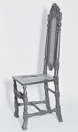
Photo 6: This turned Flemish chair is both comfortable and well-balanced. Its stiles recline for comfort, while the second bend places the pivot point behind the sitter’s center of gravity.
The leg/stile blank is sawn out of solid wood in the same manner used by cabinetmakers, but, like any part that is spindle-turned, it has to have two centers. The first center is located on the upper end of the stile. However, because the part has two angles in it, the lathe’s other center cannot be aligned with the other end of the blank (Photo 7). You have to turn the part using an artificial center located on a box-like bracket that you have to make. This is a simple project, and it should pose no problems. While the stile is being turned, the leg end of the blank is held in this bracket (Photos 8 and 9).
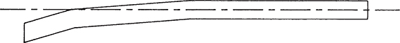
Photo 7: The shape of a leg/stile blank will prevent it from being placed between a lathe's two centers.

Photo 8: To turn a sawn leg, you need to provide a second center: This is done with a box-like bracket that is made in the shop.

Photo 9: An exploded view of the bracket you need to make for turning legs/stiles.
This bracket is essentially two sheets of 1⁄4"-thick plywood with two specially shaped shim blocks inside. The space between the blocks is the same as the outline of the rear leg. When the blank is placed in this space and the bracket reassembled, the part is held securely. The box also has a bottom board in which the second center is located.
Note that when assembled the box and the projecting stile section of the blank look very much like a Russian balalaika, a banjo-type instrument with a triangular body (Photo 10). This triangular shape is important, for its weight is evenly distributed, even though the leg/stile blank is an irregular shape. As a result of this even distribution of weight, the box and blank spin as one unit with little vibration. Of course, you should still turn at a slow speed, at approximately 600 RPM (Photo 11).

Photo 10: When the part is in the box, the assembly looks like a Russian balalaika.

Photo 11: To minimize vibration, turn chair/stiles at about 600 RPM.
The following distinctions are a point of historical interest for those who make reproductions. On banister backs, usually just the stile was turned. However, on Flemish chairs, both the stile and rear leg were more commonly turned. This means that to reproduce most Flemish chairs, you have to make two such brackets – one for turning the stile and the other for turning the rear leg.
Turning the rear leg is quite easy, for it is no more than two cylinders placed between round-ended squares. These squares are strategically located to accommodate the joints for the side and rear stretchers and seat rails. In practice, the leg end of a Flemish-type leg/stile is turned first, for the squares will still allow the part to be held securely in the bracket. The stile end is turned second.
Since you will have to assemble and disassemble the box every time you turn a leg/stile, I suggest holding it together with carriage bolts rather than screws. Glue the interior forms to one of the sheets of plywood so that they do not move when you are mounting or dismounting a part. Screw the rear board in place. Due to slight variations that occur in the shape of handmade leg/stile blanks, the center and spurs (I mount the bracket on the drive center) are not always located on exactly the same spot. Moving the center around will eventually chew a depression in the rear board, but, because of the screws, it can be easily replaced.
Also note that the bracket’s corners (closest to the stile) are rounded. This protects your left wrist and elbow. If the corners remain square, they could give you a nasty whack. Indeed, while turning leg/stiles, be very conscious of the fact that the wide end of the assembly is essentially two spinning wings. Shut off the lathe if you need to walk by it.
Even though the bracket is a simple project, it still requires time and effort to make. Such a bracket is also limiting, in that each one you make fits a blank of one precise shape. You do have the options of varying the design of the turning that you make using the box or varying the straight stile’s length (as long as you do not exceed your lathe’s capacity). However, you cannot change the leg/stile’s overall shape. Therefore, you are more likely to use this technique when you are making a production run of a particular chair design, or if you are going to add that chair to your product line and will be making small quantities frequently.

Photo 12: You can make leg stiles this way, and cut away the extra material after the stile has been turned. However this is very wasteful, and is only practical if you are making just one chair.
If you plan on making just one chair, there is a simplified technique you can use, but it is more wasteful of wood. In this case, first cut the leg/stile blank to the same shape as the entire assembly shown in Photo 10, although overall the triangular area will be slightly smaller than the bracket’s outside dimensions. Turn the stile, and then saw the waste off the leg (Photo 12). As noted, this is very wasteful, especially in contrast to using the bracket, as in that case leg/stiles blanks are “nested” and cut out one from inside the other (Photo 13).

Photo 13: The most economical way to make leg stiles is to nest them.
There is yet another method that is a modification of this technique and is slightly less wasteful. Saw the stile and one half of the balalaika shape out of a solid plank. A blank of this shape is badly out of balance, so you will have to add a counter-weight to prevent it from vibrating with enough force to make your lathe “walk” across the shop floor. Therefore, attach a wedge with dry wall screws (that are strategically placed so that they bore into the leg) where the stretcher and seat rail mortises will be cut (Photo 14). This way, the screw holes will not remain in the finished part. However you still have to cut a sizable amount of waste from the leg because they cannot be “nested.”

Photo 14: Here is another technique you can try if you are making only a few chairs. Attach a wedge-shaped piece of wood to the blank with dry wall screws. Make sure that you bore them into the location of the seat and stretcher mortise, so that their holes do not remain in the finished part.
A woodworker friend of mine once used a modification of the process just described. Instead of a wedge, he made a bracket that could be slipped over the blank. The bracket had a cast-iron counter weight that could be adjusted along a metal rod. The weight was moved along the rod to a spot that exactly counterbalanced the blank, and was then held in place with a setscrew. However one day the setscrew slipped while the lathe was turning, and the two pound counterweight was hurled across the shop as if it were shot from a cannon. Luckily no one was hurt. This experiment, obviously, proved to be unsuccessful.