
Photo 1: Compare the hand-turned baluster Windsor leg on the bottom to the mass-produced one made in a factory on a back-knife lathe. The elements on the hand-turned leg are crisp and sharp. The elements on the factory-made leg are soft and rounded.
Turned parts made in a factory on a back-knife lathe are all identical. Since most woodturning is done in factories, most of the turnings we see in our everyday lives have been mass-produced. Because machine-made turned parts are omnipresent in our society, they have become a sort of benchmark. Unwittingly, many turners allow these mass-produced, factory-made turnings to establish the standard on which they base their own work.
You can avoid this mistake if you will take a minute to compare a hand-made turning to a similar factory-made turning (Photo 1). The differences are obvious. The elements on the hand-turning are crisp and clean because the turning tools have smoothed their surfaces. The elements are all fully developed and distinct from each other, and they move dramatically and gracefully from thick to thin.
Photo 1: Compare the hand-turned baluster Windsor leg on the bottom to the mass-produced one made in a factory on a back-knife lathe. The elements on the hand-turned leg are crisp and sharp. The elements on the factory-made leg are soft and rounded.
On the factory turning, there is far less contrast between the thick and thin elements. Also, the details are rounded and blunt. The turning is soft, amorphous, and is larger in diameter than it should be. It is also covered with a matte of fine scratches. This is because the back knife cannot cut the wood cleanly. Instead, it grinds the wood away, and the turning has to be heavily sanded to make it smooth.
In short, the factory-made turning is inferior to the hand-made one. The only positive thing that can be said about it is that it is identical to all those made before it and after it. The poor level of workmanship evident in factory-made turnings should not set the standards for you.
Obviously, when turning sets of furniture or building parts for use in your woodworking, you should try to make them all identical. However, when turning by hand, exact duplication is more an ideal than a reality. Fortunately, your success is judged by the human eye, which has a limited ability to detect the level of variation that normally occurs in hand turnings. In fact, the eye seems to expect duplication, and for this reason it will not detect some astounding differences. Your inconsistencies will have to be glaring before they become noticeable. The chair shown in Photo 2 is a good example. Having made Windsor chairs for so many years, I am aware of the differences in the diameters of the chair’s two front legs, but of all the people who have seen it and admired it, no one else has spotted the problem. Their eyes see two legs of the same diameter.

Photo 2: The large vase on the left leg of this handmade Windsor chair is 5⁄16" thicker than the vase on the right leg. In spite of such a large variation, no one ever notices it unless it is pointed out to him.
This is one principle at work here that may partially explain why the discrepancy between the diameters remains undetected. The farther apart turnings are one from another, the harder it is for the eye to compare them.
Therefore, you have more leeway when making a set of dining table legs than when making a chair. Similarly, a row of balusters for a railing (parts that are closely spaced in a row) have to be more similar.
However, even this rule is not hard and fast. The distance from which the parts are meant to be viewed also plays a significant role. A roof balustrade (often called a “widow’s walk” is placed two or three stories higher than the viewer and, therefore, its balusters do not have to be as perfect as the balusters on a stair landing which are observed from only a couple of feet away.
A similar situation exists when the identical element occurs more than once on a single turning. It is difficult for the eye to compare the same element when it is repeated at the top and at the bottom of a part. They are too far from each other. On the other hand, a bobbin (which seems like such a simple element to make) presents difficulties. It is symmetrical, and any discrepancies between one side and the other are more apparent than if the two ends were separated.
When making parts in the lathe, there are, of course, situations where you have no margin for error, as, for example, when making a set of legs for a table that has both a skirt and stretcher. The squares all have to occur at the same height or the stretcher will be distorted (if it fits at all). However, should the neck of a vase on one leg have a slightly different curve than the vase neck on another leg, the discrepancy will probably never be noticed by anyone other than the most determined critic; someone who is that intent on finding a reason to criticize your work will notice something else first.
More concern than necessary is placed on duplication, and most duplication methods are much more complicated than they need to be. In years past, when hand turners provided the various building and furniture trades with huge quantities of turned parts, most of the duplication was seemingly done by eye or with help from very simple devices. Unfortunately, these devices have not survived so that they can be studied and recorded.
My own experience points out how simple duplication can be. For years, I turned baluster Windsor chair legs mostly by eye. As I show in Chapter 8, I only needed to find two diameters and two locations. After that, I did all the duplication with the help of two gauges – my eyes.
It takes a while to learn how to duplicate by sight though not anywhere near as long as you might think. In the meanwhile, you may find one or more of the techniques described below helpful. Do not hesitate to adapt other methods to suit your preferences.
Before I describe duplicating techniques, there is one important point that should be made: If you receive any tool catalogues, or have attended any of the woodworking trade shows held in major cities around the country, you have probably seen a lathe duplicator for sale. Many manufacturers make these devices. They are mounted onto a lathe to help make duplicate turnings.
Most lathe duplicators trace a pattern from a master turning. They work on the same principle as a pantograph. A moving stylus follows the outline of the original, while controlling a cutter that travels along the spinning blank.
These duplicators are popular, but are not really very useful. They do not give you either the detail quality or surface that results from hand turning. In fact, the surfaces cut by a lathe duplicator are usually very rough and coarse.
Those who sell lathe duplicators argue that the duplicator should do the rough work for you so that you can concentrate on the finish work. This sounds reasonable, but the real skill in turning is in the finish and rough work. And long before you are able to do finish work, you will have learned to do the rough work much more quickly than can a duplicator. This is why I suspect many of the duplicators that are sold are not being used. You are better off practicing and learning to turn with confidence, accuracy, and speed.
One of the most commonly recommended devices for duplicating (probably more commonly described than actually used) is the reverse template. In concept, this device is similar to that of the movable-finger, profile gauge – a tool you can buy in any hardware store. When a profile gauge is pushed against an outline of a moulding or a turning, it makes a reverse copy of the profile (Photo 3). A reverse template is also a reverse profile of the turning you want to make. The only difference is it is permanent, while you can eliminate the impression the gauge makes by realigning its fingers.
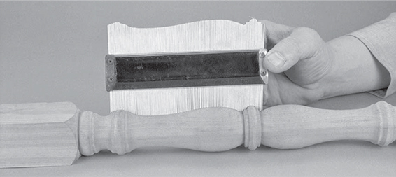
Photo 3: When pushed against a turning, a profile gauge makes a reverse copy of the profile. However, a profile gauge is not accurate enough for delicate or highly detailed work.
The template is usually made by copying the outline of the turned part from a measured drawing onto a thin, hard, homogenous material like plastic. It is then cut out with a utility knife. When the template’s contoured edge is held up to the spinning part, you can compare the profile you are making with the original (Photo 4).
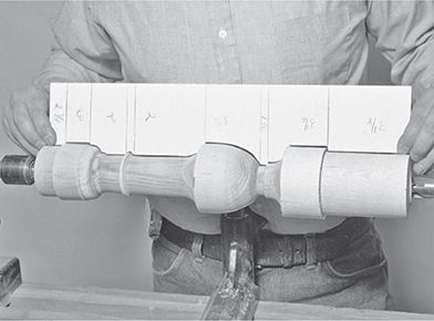
Photo 4: A reverse-profile template is similar to a profile gauge, only it makes a permanent copy.
Such templates have several disadvantages. First, they require a lot of time and work to make, and that amount of effort can only be justified if you are going to produce a large number of that particular turning. Second, the template’s profile cannot perfectly duplicate the crisp details that you can produce in a hand turning. Therefore, if you are going to use the template to duplicate parts, you will diminish the quality of your turning. If you decide only to rely on the template as a guide, there is really no reason to use it at all.
Third, if you tried to use a reverse template on a turning with square sections it would be knocked out of your hands, unless you turn off the lathe every time you check the accuracy of the turning.
For these reasons, many turners prefer to make a more simple form of template when duplicating. It is no more than a narrow board with a straight edge. Along the edge are marked the limits (the beginnings and endings) of the turning’s various details.
To use this template, hold it up to the spinning, rounded blank and transfer the limits from the template to the blank with a pencil. To make this an easier and more exact process, some turners cut V-notches that are centered on each line (Photo 5). An hexagonal pencil centers itself in such a notch, making it easier to transfer the information accurately.

Photo 5: A story board template locates critical points along the turning’s length. You can note critical diameters on the template, but you still have to set the calipers from a ruler.
When making such a template for a very simple turning (one that does not include a lot of different diameters), you can insert the sharp ends of nails at these critical points. When you push the template against the spinning blank, these points will mark or score all these lines at once.
Using a fine-point ink pen, you can also write on the template any other pertinent information you need for duplicating that turned part. For example, you might make a record of the turning’s various diameters. This way, you always have these measurements handy when you are setting your calipers.
This type of template is the turner’s equivalent of a storyboard (sometimes called a story stick) that carpenters occasionally use when laying out interior trim, or spacing clapboards. The template really does not help you to make duplicate shapes. Rather, it brings together for quick reference all the information you need for laying out a turning that you make frequently.
A similar technique can be used when you are making parts that include square sections, such as occurs on a table leg where the skirt and stretchers are joined. Lay all your turning squares together and line up the ends. It may help to hold them in a clamp so that they cannot shift. Locate the limits of the square sections on one blank, and, using a large try square, continue the layout lines across the remaining blanks (Photo 6). Once again, this technique does not help you to make more exact duplicates. Rather, it helps speed up the process.

Photo 6: Laying out the squares simultaneously on a group of blanks is not really a way to duplicate turnings, but rather a way to speed up the process.
I use another technique for duplicating, one that combines many of the concepts just described, but is more sophisticated. Whenever I have to make a turned part for the first time (whether reproducing or designing my own), I make a turning that I designate as the model.
I use the model turning in the same manner as the simple storyboard template described above. I set the model against the revolving blank and, by placing a pointed scribe (I use one leg of a divider, but you can also use a pencil) at critical points, transfer the locations of the various elements (Photo 7).

Photo 7: Place a model leg against the spinning blank to transfer the critical points. Lightly scratch these points into the surface with a divider leg.
It is also easier and quicker for me to set my calipers because I can measure directly from the model (Photo 8). This is much faster than reading a written notation and then holding the calipers against a ruler to set these measurements.

Photo 8: Transfer the diameters from the model with a pair of calipers.
My model turning can also be used in a way that is similar to the reverse template. When the model is held against the turning in the lathe, I can compare the symmetry of the various elements, much the way you can make a complete image by holding one half of a shape on the surface of a mirror. For example, two coves side by side (one on the model, the other on the work) will read as mirror images of each other and their symmetry can be easily compared.
The space between the two turnings is itself a two-sided image whose symmetry can be inspected for discrepancies. Look at the four turnings shown in Photo 9. They have been laid side by side so that you can better see the symmetrical image created by their two profiles.

Photo 9: The model turning technique is effective in that it is hard to find discrepancies, even when the turnings are laid side by side for comparison.
It is not necessary to turn off the lathe to compare the model to the turning you are making, unless the part includes square sections. In this case, the lathe needs to be turned off so that the revolving square does not knock against the stationary one, damaging one or both of them.
When you are done with a project, store the model part (or models, if there is more than one) for future reference. Keep it with any other models you have made. If you ever have to make any of those parts again, their models will quickly give you all the information needed.