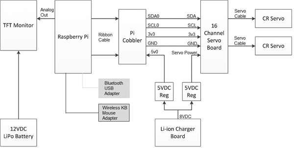
Figure 13–1 Block diagram of the robotic car electrical components.
This is the second of two chapters that will show you how to complete the RasPi-controlled robotic car, a project that was started in Chap. 12. This chapter deals with the electrical wiring and most of the programming required to control the car.
Figure 13–1 is a block diagram showing all of the robotic car electrical components.

Figure 13–1 Block diagram of the robotic car electrical components.
The RasPi is powered from the Li-ion charger board; however, that board provides only an 8-V DC output. The voltage is converted to 5 V DC by a small regulator board that uses an LM7805 three terminal chip with some auxiliary capacitors. Figure 13–2 shows the regulator schematic.

Figure 13–2 5-V DC regulator schematic.
The 5-V output is connected to the Pi Cobbler’s 5-V pin 0. Technically, this arrangement is known as back feeding because the 5-V 0 pin is normally an output, not an input. However, it makes no difference electrically if you supply or take off power from a parallel-connected power bus. By following this approach, you avoid having to hack up a micro USB connector and cable through which the RasPi is normally powered.
Shown on the block diagram is another 5-V DC regulator that provides power to the servo motor input on the 16-channel servo control board (now simply referred to as the servo board). You might wonder why I did this instead of paralleling the output already connected to the RasPi. The answer is that I wanted to avoid the situation in which a brief high-current demand from the servo motors would cause the regulator voltage output to drop below the minimally acceptable voltage for the RasPi, thus causing it to stop running.
The logic on the servo board is fed from the Pi Cobbler’s 3-V pin 3 for reasons already stated in Chap. 12.
The TFT monitor requires 270 mA at 12 V DC to operate. This requirement necessitated that an additional lithium-ion polymer (Li-Po) battery be added for the sole purpose of powering the monitor. The Li-Po battery is normally used in a radio-controlled aircraft application where it can supply fairly high current for short time bursts. However, it fits this situation quite well, being able to power the monitor for about eight hours, given its 2200-mA/h rating. Figure 13–3 shows this battery.
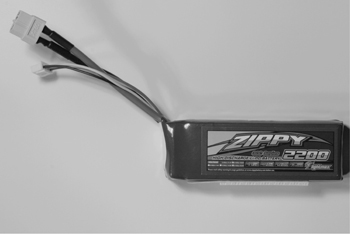
Figure 13–3 The Li-Po battery for the TFT monitor.
CAUTION The Li-Po battery must be recharged only with an approved charger designed for it. Under no circumstances should you use an automotive 12-volt charger with this battery. Bad things, such as a fire, will happen!
You may also have noticed a Velcro™ strip attached to the underside of the battery. I used this strip as a convenient way to mount the battery and to allow it to be quickly removed for a recharge.
There are two Bluetooth micro USB adapters plugged into the RasPi’s USB slots. One is for the Wiimote, and the other is for the wireless keyboard and mouse unit that I use with the car. Figure 13–4 shows this Logitech model K400r keyboard and mouse combination. I have found it to be extremely reliable and very moderately priced.
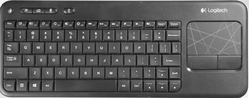
Figure 13–4 Logitech K400r wireless keyboard/mouse.
The servo motors connect to the servo board by means of the three lead cables already attached to the motors. Each cable plugs directly into one of the 16 three pin connectors. I used connector numbers 0 and 1 for the right- and left-hand motors, respectively. It doesn’t matter which servo connectors are used as long as the software is appropriately modified to reflect the actual connectors. There is a more or less standard color code used for servo cables as follows:
red = power
white = signal
black = ground
I have one last item to mention regarding the wiring: the Li-ion charger board’s power socket should be accessible so that it can be recharged. Figure 13–5 shows such an arrangement on the prototype robot car.
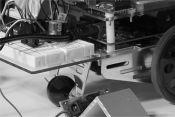
Figure 13–5 The wall wart power cord plugged into the Li-ion charger board.
Notice also that I had to remove the RasPi 5-V regulator board from the breadboard in order to provide clearance for the power cord. I soldered two pins to the regulator so that the board plugs directly into the 5-V and GND strips that are the outermost strips on the breadboard. It makes it very convenient to have a pluggable regulator for use with a breadboard.
The servo board communicates with the RasPi using the I2C protocol. The I2C RasPi setup, which has already been discussed in Chap. 12, must be completed before proceeding with the remaining software installations.
The first step in setting up the car to use Bluetooth is to plug in the Bluetooth adapter. Just make sure the RasPi is not running. Figure 13–6 shows the V4 Targus Bluetooth adapter that I used in this project. I am sure that similar type adapters will function equally as well, but just ensure that you choose a high-speed class-4 device.
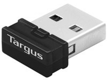
Figure 13–6 Targus Bluetooth adapter.
Now, start the RasPi and check that the Wheezy distribution has recognized the Bluetooth adapter. Enter the following at a command line prompt:

The listing in Fig. 13–7 shows that the adapter has been found and an appropriate driver loaded for it. The Targus adapter apparently uses a Broadcom chip, from the same fine company that makes the RasPi core processor.
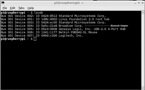
Figure 13–7 lsusb listing.
You next need to download and install the bluetooth software package. Enter the following at a command line prompt:

(Be patient, this takes a while.)
Enter the following to check if the Bluetooth service is running:

Figure 13–8 shows the status for an up-and-running service.

Figure 13–8 Bluetooth status.
If the status shows that it is not running, enter this command:

Reenter the above status command to confirm that the service is now running.
Enter the following command to check on the adapter’s address:

Figure 13–9 shows the resulting screen display of the address of the Bluetooth adapter. The address is not really needed, but it does check that the hcitool application was loaded with the Bluetooth package.

Figure 13–9 Bluetooth adapter address.
The stage is now set to start scanning for Bluetooth-enabled devices. Gather up your Wiimote and ensure that it has fresh batteries installed. Enter the following command to start the scan:

You will see “Scanning …” displayed on the console screen. Simultaneously press the 1 and 2 buttons on the Wiimote to put it into the discovery mode. Don’t fret if it takes several tries to discover the remote. The screen will show a time-out if the RasPi doesn’t discover the remote within 5 to 10 seconds. Just try again. Eventually you will be rewarded with a display, as shown in Fig. 13–10.

Figure 13–10 Wiimote discovered.
Notice that all Bluetooth-enabled devices in the immediate vicinity are discovered. In Fig. 13–10, both the Wiimote (Nintendo RVL-CNT-01) and an HP wireless printer were discovered. Don’t be concerned with conflicting Bluetooth devices because the protocol is quite capable of keeping track of which device needs to be addressed by an application.
Another software package is needed to enable a Python program to interface to a Bluetooth device. This package is named cwiid and is downloaded and installed by entering:

This package contains all the necessary applications that allow the Wiimote to interface with a user-created Python program. I would also like to extend my thanks to Brian Hensley (www.brianhensley.net) for his fine tutorial on using the Wiimote with the RasPi. It was invaluable in helping me to create the following programs.
However, before discussing an actual program, I need to show you how the Wiimote buttons are set with regard to state values, which are those numbers sent to the RasPi, indicating their corresponding buttons have been pushed. Figure 13–11 is a Wiimote with all the corresponding state values superimposed on the image.
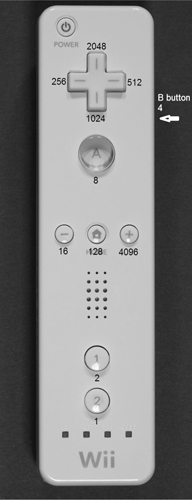
Figure 13–11 Wiimote with state values.
For instance, if the forward button of the four-way switch is pressed, a value of 2048 will be transmitted via the Bluetooth connection to the RasPi. Likewise, if the “–” button is pressed, a value of 16 is sent. The values are also cumulative in case of combination button presses. For example, simultaneously pressing the 1 button and the home button will cause a value of 130 to be sent: the sum of the home button value of 128 and the 1 button value of 2. The application becomes a matter of decoding the values received and figuring out what actions to take based upon those values.
I created a simple test program named Wiimote_Test.py that establishes a Bluetooth connection between the car and the Wiimote. The four-way switch on the Wiimote is then used to send different values, depending upon which switch is pressed. Enter the following to run this program:

Figure 13–12 shows the result obtained by first establishing a connection and then pressing all four switches.

Figure 13–12 Wiimote_Test.py program results.
The Python code for Wiimote_Test.py is available from the book’s website, www.mhprofessional.com/raspi, and is also listed below:
Wiimote_Test.py
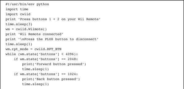

The expression “wm = cwiid.Wiimote()” is all that it takes to instantiate an object that logically represents the Wiimote. The object is then placed in the proper state to report its state value by the program line “wm.rpt_mode = cwiid.RPT_BTN.” From then on, all that needs to be done to retrieve the state value is to use the expression “wm.state[‘buttons’].”
The Wiimote disconnects, and the program stops when the + button is pushed. The expression “while (wm.state[‘buttons’] < 4096):” establishes a loop and waits for the state value to exceed 4096 to stop the looping. Using a high value for this state change precludes any unintended program stoppage due to combination button presses, which is something to keep in mind when you start to create your own programs.
The program requirements for controlling the car were deliberately made very simple. The car was to go forward when the forward button on the four-way Wiimote switch was pressed. It was to turn right when the right button was pressed and turn left when the left button was pressed. It was to stop when the back button was pressed. Obviously, much more sophisticated control commands could be devised, but this simple set was deemed adequate to prove out the basic car functionality.
The program follows the same state variable detection and corresponding action as was demonstrated in the test program, only this time the commands are being sent to the servo control board, which in turn, controls the servo motors. This program would not function except for the brilliant PWM servo library provided by Adafruit Industries. This library enables PWM commands in Python that directly control the servo board and indirectly control the servo motors.
The only tricky part in developing this program was determining the PWM parameters that set the servo motors rotating at the correct angular velocity and direction. These are shown in the code as constants:

You will have to experiment with different values if you desire to have the robot go a bit faster. I know that these values make the robot travel in a straight line when so commanded.
The program is named Robot_Car.py and is available from the book’s website. The program listing along with some amplifying comments can be found on page 172.
The program line “pwm = PWM(0x40, debug = True” sets up a PWM object that is at I2C address 0 × 40. This is how multiple I2C devices can be configured when they all are attached on the same bus lines.
The program segment:

drives the car forward when the forward button is pressed. You just need to press the back button to stop this motion. The same holds true for turning right or left.
The car is essentially a peripheral for the RasPi, which means that you must start the computer as you would normally do and simply enter the command to run the Robot_Car.py program as shown below:

You would then simultaneously press the 1 and 2 buttons on the Wiimote to connect to the RasPi via Bluetooth. Next, you would operate the car by using the four-way switch on the Wiimote to control the direction of the car. That’s it. Press the “+” button to disconnect and stop the Bluetooth session.
The following would be interesting and exciting modifications to this project to expand its usefulness and hopefully the learning experience:
 Add a 5-V DC powered USB hub to the existing two USB ports that are both used. Adding a Wi-Fi adapter would provide a wireless networking capability and Internet access.
 Add a video camera, such as the GoPro Hero3. This unit has Wi-Fi connectivity, and is capable of being remotely controlled by either its own remote control accessory or an Android smartphone or tablet running the GoPro app. The remote control and Android app both have a real-time video preview function.
 Add an ultrasonic sensor that is capable of detecting objects in the forward path of the car. The Python program can easily be modified to handle sensor inputs and modify the path accordingly.
 Add an IR sensor to detect IR beams to redirect the car, basically creating an invisible fence or barrier.
 Add a GPS sensor to map the path of the car, assuming it travels more than a few meters. The Ultimate GPS receiver discussed in an earlier chapter would be an ideal unit to install on the car. The path taken could be recorded in the RasPi SD card and later sent to Google Earth for display in that application.
 Add swarm or hive behavior if you happen to have an additional car or know someone with one. The RasPi can easily handle the computing challenge that it takes to enable this type of collective behavior. The cars should be able to talk with one another using their installed adapters.
 Add an IR light and an IR sensitive camera to allow the car to maneuver in total darkness. This would be a very interesting and informative task, since rescue robots need to have this capability.
As you might imagine, many more items could be added to this list. It really is only limited by your imagination. The robot car built in this project is only a start to bigger and much better projects.
This project commenced with an overview of the car’s final form. Next came specific build instructions for the chassis as well as for the “sandwich” construction that holds the various boards that make up the car.
A discussion followed regarding the servo drive motors and the associated PWM control signals. Then we looked at the procedure for setting up the RasPi to run the I2C protocol that is necessary to communicate with the 16-channel servo control board.
Some preliminary testing was next shown that proved the I2C interface functioned as expected.
A complete block diagram was shown to assist in connecting all the component boards and modules that make up the car.
After that step came a detailed procedure for setting up Bluetooth to run on the RasPi. A companion software package named cwiid was downloaded and installed to enable a Python program to control a Wii remote control (Wiimote).
A simple Python program was shown that allowed a user to control the car using a Wiimote. The car can go forward, turn right or left, and stop.
The project finished with many suggestions for future car expansions and modifications.