IN THIS CHAPTER
Summary: Light rays travel in a straight line, except when they’re bent or reflected. The rules of refraction and reflection can be used to figure out how the light’s path changes.
Key Ideas
 When light hits an interface between materials, the light reflects and refracts. The angle of refraction is given by Snell’s law.
Total internal reflection can occur when light strikes a higher-index material at a large incident angle.
Concave mirrors and convex lenses are optical instruments which converge light to a focal point. Concave lenses and convex mirrors are optical instruments which cause light to diverge.
Virtual images are formed right-side up; real images are upside down and can be projected on a screen.
Relevant Equations
Snell’s law (for refraction):
n1sinθ1 = n2sinθ2
Finding the critical angle for total internal reflection:

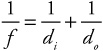
The lensmaker’s equation/mirror equation:
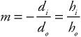
Magnification equation:
Optics is the study of light and how it gets bent and reflected by lenses and mirrors. If you’re tired of problems involving heavy calculation, optics will come as a breath of fresh air. It will feel like a springtime breeze, a splash of cool water, an Enya song. Why? Because, for the most part, optics problems will not require a lot of math. Instead, you’ll have to draw pictures. (Finally, a physics topic for the artist-at-heart!)
In addition to changing its speed and its wavelength, light can also change its direction when it travels from one medium to another. The way in which light changes its direction is described by Snell’s law.
n1sinθ1 = n2sinθ2 |
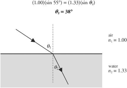
To understand Snell’s law, it’s easiest to see it in action. Figure 24.1 should help.
In Figure 24.1, a ray of light is going from air into water. The dotted line perpendicular to the surface is called the “normal.”1 This line is not real; rather it is a reference line for use in Snell’s law. In optics, ALL ANGLES ARE MEASURED FROM THE NORMAL, NOT FROM A SURFACE!

As the light ray enters the water, it is being bent toward the normal. The angles θ1 and θ2 are marked on the figure, and the index of refraction of each material, n1 and n2, is also noted. If we knew that θ1 equals 55°, for example, we could solve for θ2 using Snell’s law.
Figure 24.1 Light bending as it travels from one material (air) to another (water).
Whenever light goes from a medium with a low index of refraction to one with a high index of refraction—as in our drawing—the ray is bent toward the normal. Whenever light goes in the opposite direction—say, from water into air—the ray is bent away from the normal.
If you have a laser pointer, try shining it into some slightly milky water . . . you’ll see the beam bend into the water. But you’ll also see a little bit of the light reflect off the surface, at an angle equal to the initial angle. (Careful the reflected light doesn’t get into your eye!) In fact, at a surface, if light is refracted into the second material, some light must be reflected.
Sometimes, though, when light goes from a medium with a high index of refraction to one with a low index of refraction, we could get total internal reflection. For total internal reflection to occur, the light ray must be directed at or beyond the critical angle.
Critical Angle: The angle past which rays cannot be transmitted from one material to another, abbreviated θc |

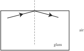
Again, pictures help, so let’s take a look at Figure 24.2.
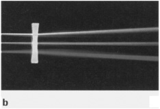
In Figure 24.2, a ray of light shines up through a glass block. The critical angle for light going from glass to air is 42°; however, the angle of the incident ray is greater than the critical angle. Therefore, the light cannot be transmitted into the air. Instead, all of it reflects inside the glass. Total internal reflection occurs anytime light cannot leave a material.
Figure 24.2 Light undergoing total internal reflection.
Okay, time to draw some pictures. Let’s start with plane mirrors.
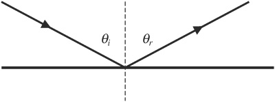
The key to solving problems that involve plane mirrors is that the angle at which a ray of light hits the mirror equals the angle at which it bounces off, as shown in Figure 24.3. In other words—or, more accurately, “in other symbols”—θ i = θr where θi is the incident2 angle, and θr is the reflected angle.
Figure 24.3 Light reflecting off a plane mirror.
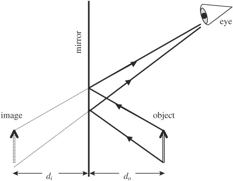
So, let’s say you had an arrow, and you wanted to look at its reflection in a plane mirror. We’ll draw what you would see in Figure 24.4.
The image of the arrow that you would see is drawn in Figure 24.4 in dotted lines. To draw this image, we first drew the rays of light that reflect from the top and bottom of the arrow to your eye. Then we extended the reflected rays through the mirror.
Whenever you are working with a plane mirror, follow these rules:
• The image is upright. Another term for an upright image is a virtual image.
• The image is the same size as the original object. That is, the magnification, m, is equal to 1.
• The image distance, di, equals the object distance, do.
Figure 24.4 Reflection of an arrow in a plane mirror.
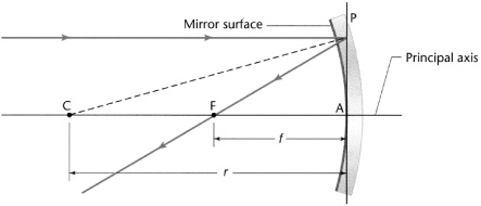
A more challenging type of mirror to work with is called a spherical mirror. Before we draw our arrow as it looks when reflected in a spherical mirror, let’s first review some terminology (this terminology is illustrated in Figure 24.5).
Figure 24.5 Features of a spherical mirror.
A spherical mirror is a curved mirror—like a spoon—that has a constant radius of curvature, r.The imaginary line running through the middle of the mirror is called the principal axis. The point labeled “C,” which is the center of the sphere, lies on the principal axis and is located a distance r from the middle of the mirror. The point labeled “F” is the focal point, and it is located a distance f, where f = (r/2), from the middle of the mirror. The focal point is also on the principal axis. The line labeled “P” is perpendicular to the principal axis.

There are several rules to follow when working with spherical mirrors. Memorize these.
• Incident rays that are parallel to the principal axis reflect through the focal point.
• Incident rays that go through the focal point reflect parallel to the principal axis.
• Any points that lie on the same side of the mirror as the object are a positive distance from the mirror. Any points that lie on the other side of the mirror are a negative distance from the mirror.
• 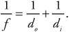
That last rule is called the “mirror equation.” (You’ll find this equation to be identical to the “lensmaker’s equation” later.)
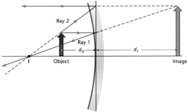
To demonstrate these rules, we’ll draw three different ways to position our arrow with respect to the mirror. In the first scenario, we’ll place our arrow on the principal axis, beyond point “C,” as shown in Figure 24.6.
Notice that the image here is upside down. Whenever an image is upside down, it is called a real image. A real image can be projected onto a screen, whereas a virtual image cannot.3
The magnification, m, is found by
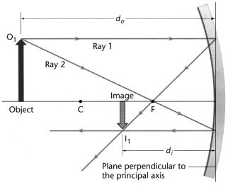
Figure 24.6 Object located beyond the center point of a spherical mirror.
When the magnification is negative, the image is upside down. By convention, the height of an upside-down image is a negative value. When the magnification is positive, the image is rightside-up, and the height is a positive value. Plugging in values from our drawing in Figure 24.6, we see that our magnification should be less than 1, and the image should be upside-down. Which it is. Good for us.
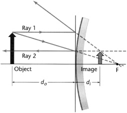
Now we’ll place our arrow between the mirror and “F,” as shown in Figure 24.7. When an object is placed between “F” and the mirror, the image created is a virtual image—it is upright.
Figure 24.7 Object located between focal point of a spherical mirror and the mirror itself.
Finally, we will place our object on the other side of the mirror, as shown in Figure 24.8. Now, in Figure 24.8, we have a convex mirror, which is a diverging mirror—parallel rays tend to spread away from the focal point. In this situation, the image is again virtual.
Figure 24.8 Object located on the convex side of a spherical mirror.
When we use the mirror equation here, we have to be especially careful: d0 is positive, but both di and f are negative, because they are not on the same side of the mirror as the object.
Note that the convex (diverging) mirror cannot produce a real image. Give it a try— you can’t do it!
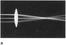
We have two types of lenses to play with: convex and concave. A convex lens, also known as a “converging lens,” is shown in Figure 24.9a.
Figure 24.9a Convex lens.
And a concave lens, or “diverging lens,” is shown in Figure 24.9b.
Figure 24.9b Concave lens.
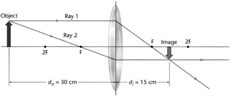
We’ll start by working with a convex lens. The rules to follow with convex lenses are these:
• An incident ray that is parallel to the principal axis refracts through the far focal point.
• An incident ray that goes through near focal point refracts parallel to the principal axis.
• The lensmaker’s equation and the equation to find magnification are the same as for mirrors. In the lensmaker’s equation, f is positive.
Want to try these rules out? Sure you do. We’ll start, in Figure 24.10, by placing our arrow farther from the lens than the focal point.
Figure 24.10 Object located farther from a convex lens than the focal point.
We could also demonstrate what would happen if we placed our object in between the near focal point and the lens. But so could you, as long as you follow our rules. And we don’t want to stifle your artistic expression. So go for it.4
A 3-cm-tall object is placed 20 cm from a converging lens. The focal distance of the lens is 10 cm. How tall will the image be? |
We are given do and f. So we have enough information to solve for di using the lensmaker’s equation.
Solving, we have di = 20 cm. Now we can use the magnification equation.
Our answer tells us that the image is exactly the same size as the object, but the negative sign tells us that the image is upside-down. So our answer is that the image is 3 cm tall, and that it is real.
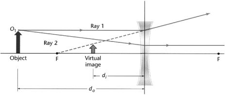
When working with diverging lenses, follow these rules:
• An incident ray parallel to the principal axis will refract as if it came from the near focal point.
• An incident ray toward the far focal point refracts parallel to the principal axis.
• The lensmaker’s equation and the magnification equation still hold true. With diverging lenses, though, f is negative.
We’ll illustrate these rules by showing what happens when an object is placed farther from a concave lens than the focal point. This is shown in Figure 24.11.
Figure 24.11 Object located farther from a concave lens than the focal point.
The image in Figure 24.11 is upright, so we know that it is virtual.
Now go off and play with lenses. And spoons. And take out that box of crayons that has been collecting dust in your cupboard and draw a picture. Let your inner artist go wild. (Oh, and do the practice problems, too!)
 Practice Problems
Multiple Choice:
1. In an aquarium, light traveling through water (n = 1.3) is incident upon the glass container (n = 1.5) at an angle of 36° from the normal. What is the angle of transmission in the glass?
(A) The light will not enter the glass because of total internal reflection.
(B) 31°
(C) 36°
(D) 41°
(E) 52°
2. Which of the following optical instruments can produce a virtual image with magnification 0.5?
I. convex mirror
II. concave mirror
III. convex lens
IV. concave lens
(A) I and IV only
(B) II and IV only
(C) I and II only
(D) III and IV only
(E) I, II, III, and IV
3. Light waves traveling through air strike the surface of water at an angle. Which of the following statements about the light’s wave properties upon entering the water is correct?
(A) The light’s speed, frequency, and wavelength all stay the same.
(B) The light’s speed, frequency, and wavelength all change.
(C) The light’s speed and frequency change, but the wavelength stays the same.
(D) The light’s wavelength and frequency change, but the light’s speed stays the same.
(E) The light’s wavelength and speed change, but the frequency stays the same.
4. An object is placed at the center of a concave spherical mirror. What kind of image is formed, and where is that image located?
(A) A real image is formed at the focal point of the mirror.
(B) A real image is formed at the center of the mirror.
(C) A real image is formed one focal length beyond the center of the mirror.
(D) A virtual image is formed one focal length behind the mirror.
(E) A virtual image is formed one radius behind the mirror.
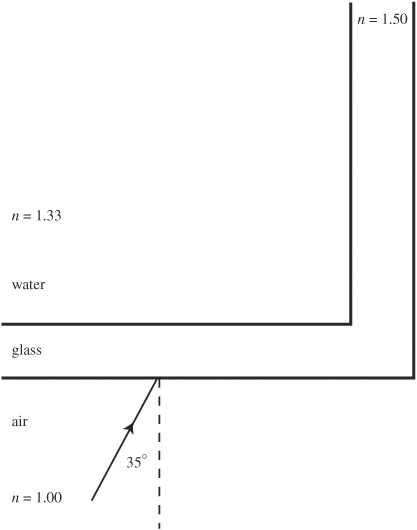
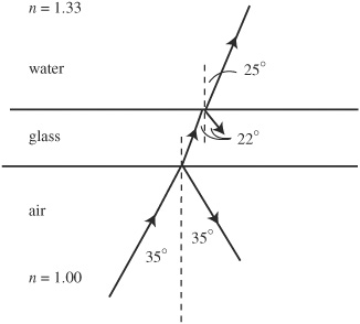
5. Light traveling through air encounters a glass aquarium filled with water. The light is incident on the glass from the front at an angle of 35°.
(a) At what angle does the light enter the glass?
(b) At what angle does the light enter the water?
(c) On the diagram above, sketch the path of the light as it travels from air to water. Include all reflected and refracted rays; label all angles of reflection and refraction.
After entering the water, the light encounters the side of the aquarium, hence traveling back from water to glass. The side of the tank is perpendicular to the front.
(d) At what angle does light enter the glass on the side of the aquarium?
(e) Does the light travel out of the glass and into the air, or does total internal reflection occur? Justify your answer.
1. B—If you had a calculator, you could use Snell’s law, calling the water medium “1” and the glass medium “2”: 1.3-sin 36° = 1.5-sin θ2. You would find that the angle of transmission is 31°. But, you don’t have a calculator . . . so look at the choices. The light must bend toward the normal when traveling into a material with higher index of refraction, and choice B is the only angle smaller than the angle of incidence. Choice A is silly because total internal reflection can only occur when light goes from high to low index of refraction.
2. A—The converging optical instruments— convex lens and concave mirror—only produce virtual images if the object is inside the focal point. But when that happens, the virtual image is larger than the object, as when you look at yourself in a spoon or a shaving mirror. But a diverging optical instrument—a convex mirror and a concave lens—always produces a smaller, upright image, as when you look at yourself reflected in a Christmas tree ornament.
3. E—The speed of light (or any wave) depends upon the material through which the wave travels; by moving into the water, the light’s speed slows down. But the frequency of a wave does not change, even when the wave changes material. This is why tree leaves still look green under water—color is determined by frequency, and the frequency of light under water is the same as in air. So, if speed changes and frequency stays the same, by v = λf, the wavelength must also change.
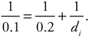
4. B—You could approximate the answer by making a ray diagram, but the mirror equation works, too:
Because the radius of a spherical mirror is twice the focal length, and we have placed the object at the center, the object distance is equal to 2f Solve the mirror equation for di by finding a common denominator:
This works out to (f)(2f)/(2f - f) which is just 2f. The image distance is twice the focal length, and at the center point. This is a real image because di is positive.
5. (a) Use Snell’s law: n1 sin θ1 = n2 sin θ2. This becomes 1.0 sin 35° = 1.5 sin θ2. Solve for θ2 to get 22°.
(b) Use Snell’s law again. This time, the angle of incidence on the water is equal to the angle of refraction in the glass, or 22°. The angle of refraction in water is 25°. This makes sense because light should bend away from normal when entering the water because water has smaller index of refraction than glass.
(c) Important points:
*Light both refracts and reflects at both surfaces. You must show the reflection, with the angle of incidence equal to the angle of reflection.
*We know you don’t have a protractor, so the angles don’t have to be perfect. But the light must bend toward normal when entering glass, and away from normal when entering water.
(d) The angle of incidence on the side must be measured from the normal. The angle of incidence is not 25°, then, but 90 - 25 = 65°. Using Snell’s law, 1.33 sin 65° = 1.50 sin θ2. The angle of refraction is 53°.
(e) The critical angle for glass to air is given by sin θc = 1.0/1.5. So θc = 42°. Because the angle of incidence from the glass is 53° [calculated in (d)], total internal reflection occurs.
Rapid Review• Snell’s law describes how the direction of a light beam changes as it goes from a material with one index of refraction to a material with a different index of refraction.
• When light is directed at or beyond the critical angle, it cannot pass from a material with a high index of refraction to one with a low index of refraction; instead, it undergoes total internal reflection.
• When solving a problem involving a plane mirror, remember (1) the image is upright (it is a virtual image); (2) the magnification equals 1; and (3) the image distance equals the object distance.
• When solving a problem involving a spherical mirror, remember (1) incident rays parallel to the principal axis reflect through the focal point; (2) incident rays going through the focal point reflect parallel to the principal axis; (3) points on the same side of the mirror as the object are a positive distance from the mirror, and points on the other side are a negative distance from the mirror; and (4) the lensmaker’s equation (also called the mirror equation in this case) holds.
• When solving problems involving a convex lens, remember (1) incident rays parallel to the principal axis refract through the far focal point; (2) incident rays going through the near focal point refract parallel to the principal axis; and (3) the lensmaker’s equation holds, and f is positive.
• When solving problems involving a concave lens, remember (1) incident rays parallel to the principal axis refract as if they came from the near focal point; (2) incident rays going toward the far focal point refract parallel to the principal axis; and (3) the lens-maker’s equation holds with a negative f.