Voltage-Gated Ion Channels
Pascal Wallisch
This chapter will explore the dynamics of ion channels using methods similar to those introduced by Hodgkin and Huxley in 1952. You will derive ordinary differential equations that approximate real ion channel behavior and solve these equations using a numerical integrator written in the MATLAB® software. Finally, you will visualize the dynamics by predicting current responses to single channel voltage-clamp experiments.
Keywords
ion channels; gating variables; ligand gated; voltage gated; Runge-Kutta method
25.1 Goal of This Chapter
This chapter will explore the dynamics of ion channels using methods similar to those introduced by Hodgkin and Huxley in 1952. You will derive ordinary differential equations that approximate real ion channel behavior and solve these equations using a numerical integrator written in the MATLAB® software. Finally, you will visualize the dynamics by predicting current responses to single channel voltage-clamp experiments.
25.2 Background
Ion channels are a class of multimeric transmembrane proteins with a hydrophilic pore that facilitates transport of ions across the cell membrane. The size of the ion channel pore and the charge of amino acids near the opening of the pore help exclude entry of some ions while promoting the entry of others. This confers upon the ion channel a selective permeability to different ions. Several factors can induce conformational changes in the ion channel, altering its quaternary structure and therefore its permeability. These factors are referred to as gating variables because they function as a gate between the ion channels’ different conformational states.
Most ion channels are classified according to the nature of their gating and their selectivity of ions. The largest subclasses of ion channels classified by gating are the ligand-gated and voltage-gated ion channels. Ligand-gated ion channels change conformation when a ligand binds to them. The most common ligand-gated ion channels found at the post-synaptic membrane of neurons include NMDA, kainate, AMPA, and GABAA receptors.
The second class of ion channels, voltage-gated ion channels, undergo conformational changes corresponding to alterations in membrane potential. Voltage-gated ion channels can show selectivity for sodium, potassium, or calcium. In this chapter you will model voltage-gated potassium channels (Kv channels) and voltage-gated sodium channels (Nav channels). Kv channels generally gate between two conformations—an open conformation permeable to potassium and a closed conformation impermeable to potassium—while Nav channels often gate between three stable conformations—an open conformation permeable to sodium, a closed conformation impermeable to sodium, and an inactive conformation also impermeable to sodium. Although both the inactive and closed states of Nav channels are impermeable to sodium, they represent different conformational states of the channel and have different kinetics.
25.2.1 The Model
Suppose you are interested in building a model to predict the current response to a single ion channel voltage-clamp experiment. Since ionic currents pass through the ion channel to enter the cell, you can consider the ion channel as an electrical resistor whose resistance depends on the conformational state of the ion channel. The equation that relates the resistance of a resistor, R, to the current it passes, I, and the voltage drop across the resistor, V, is Ohm’s law:
 (25.1)
If you divide this equation through by the resistance, then you can write this equation as
 (25.2)
where g is the conductance of the resistor (note g=1/R). Finally, if you suppose that the conductance is directly proportional to the probability that the channel is in the open conformation, then Equation 25.1 becomes
 (25.3)
where gmax is the maximum conductance of the channel, and Po is the probability that the channel is in the open conformation. Therefore, determining the conductance of the channel is equivalent to determining the probability that the channel is open.
25.2.2 Kv Channel
Let’s begin with the simplest case, the Kv channel. For the Kv channel, Equation 25.3 will take the form
 (25.4)
where  is the maximum conductance of the Kv channel, and n is the probability that the channel is in the open conformation. Next, suppose that the ion channel can exist only in an open or closed conformation as depicted by the reversible reaction in the equation
 (25.5)
where k1 is the rate the channel goes from closed to open, and k−1 is the rate the channel goes from open to closed. Next, assume that the change in the probability of open channels over time is equal to the probability of the channel being closed, and then going from closed to open (at rate k1), minus the probability of its being open, and then closing (at rate k−1). This can be represented by the equation
 (25.6)
since all channels are either open or closed. Now further assume that at time t=0 all the channels are closed so that n(0)=0. Finally, recall that for a voltage-gated ion channel the gating between conformational states depends on the membrane potential, so the rates k1 and k−1 are both functions of voltage. If you were modeling ligand-gated ion channels, then these rates would depend on the concentration of the ligand. Hodgkin and Huxley used voltage clamp experiments to help determine these rates. In this chapter assume the following functional forms (see Hodgkin and Huxley, 1952) for the transition rates between conformational states of the Kv channel:
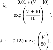 (25.7)
25.2.3 The Nav Channel
The Nav channel is slightly more complicated, since it has three stable confirmations and therefore a greater number of possible transitions between conformational states. For simplicity, we will ignore transitions between inactive and closed conformational states, and assume that the channel is governed by the following reversible reactions that act independently of each other:
 (25.8)
If you let m represent the probability of the channel being open given that it was closed previously, and you let h represent the probability of the channel being open given that it was inactive previously, then Equation 25.3 takes on the form:
 (25.9)
where  The previous reversible reactions lead to the following differential equations:
 (25.10)
For the Nav open-close kinetics, assume:
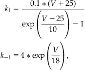 (25.11)
and for Nav inactivation kinetics, assume:
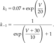 (25.12)
Simple intuition has led naturally to a model that expresses the current you expect to flow through a channel in terms of a differential equation for the probability of the channel being open.
Next, we will discuss a simple algorithm to numerically solve differential equations such as Equation 25.6.
25.2.4 Solving Differential Equations Numerically
To understand the current-voltage properties of an ion channel, you can solve an ordinary differential equation describing the probability of the channel being open given the initial condition that Po(0)=0. In general, solving differential equations can be very tricky (if not impossible), but some simple techniques for approximating solutions do exist. Perhaps the simplest method for approximating the solution to a differential equation is Euler’s method. It is based on the definition of the derivative:
 (25.13)
which for small nonzero values of Δx implies that:
 (25.14)
Equation 25.14 lets you determine an approximation for the value of a function f at a point (x+Δx) given information about the value of the function of f at x and the derivative of f. You can examine Euler’s method by choosing a differential equation whose solution is known and compare it to the approximation obtained from Equation 25.14. Now try to apply Equation 25.14 to a simple differential equation:
 (25.15)
This differential equation has the obvious solution f(x)=x2+1, since it satisfies Equation 25.15 with the condition that f(0)=1. To approximate the solution to this equation using Euler’s method, you proceed by first plugging Equation 25.15 into Equation 25.14 to get:
 (25.16)
Next, you choose Δx=0.1 (i.e., something small, since the approximation is most valid for small Δx) and x=0 and plug into Equation 25.16 to obtain:
 (25.17)
This equation can be repeated to give an estimate of f(0.2) such that:
 (25.18)
where the previous value f(0.1) has been substituted into Equation 25.16 instead of the initial condition. Although you might be tempted to approximate f(0.2) directly from the initial condition by letting Δx=0.2, recall that the approximation is best when Δx is as close to 0 as possible. This procedure can be repeated to approximate f(x) over any range of x desired. Of course, without the help of modern computers, this method would be too laborious to be practical for any moderately large range of x.
Another method for numerically solving differential equations is known as the Runge-Kutta method (RK method). We shall derive the second-order RK method for the general differential equation:
 (25.19)
with the initial condition y(xo)=yo. Note that the ion-channel gating Equations 25.6 and 25.10 are of this general form. Our first step in deriving the formulae for the RK method is to assume that the numerical solution y(x) that we are looking for has a Taylor series expansion that converges on the interval I for which we want to find the numerical solution. If it does, then:
 (25.20)
is the Taylor series expansion. Let us define Δx=(x−xo), and substitute this into Equation 25.20, which gives:
 (25.21)
We can make a polynomial approximation to the series in Equation 25.21. If we make a second-order approximation, then:
 (25.22)
Notice that the first-order approximation reduces to the key equation in iterating Euler’s method (see Equation 25.14). Next, we realize that Equation 25.19 gives us a substitution for y’(xo)=f(xo, yo). We can take the derivative of Equation 25.19 to obtain a substitution for y’’(xo) as follows:
 (25.23)
Making these two substitutions into Equation 25.22 gives:
 (25.24)
If f were a function whose derivatives could easily be calculated, then we could simply end here, and use Equation 25.24 in much the same way as we used Equation 25.14 to iterate Euler’s method. This does not happen often, however, so we will try to find a simplification for Equation 25.24 that does not involve partial derivatives of f. Since y was assumed to have a Taylor series expansion, then its derivative does too, so by Equation 25.19 f must also have a Taylor series expansion. The Taylor series expansion of f is slightly complicated, however, since f is a multivariable function. The Taylor expansion is as follows:
 (25.25)
The terms shown in Equation 25.25 are through first order. If we let a=Δx and b=Δx*f(xo,yo), and we substitute these into Equation 25.25, keeping only up to the first-order terms of the series, then we get:
 (25.26)
If we subtract f(xo,yo) from the right-hand side of Equation 25.26 and multiply through by Δx/2, we obtain:
 (25.27)
The right-hand side of Equation 25.27 is the last term of Equation 25.24. If we now substitute Equation 25.27 into Equation 25.24, then we will have removed the partial derivatives of f. After slight simplification we achieve:
 (25.28)
We now have an equation to give us the next y value given the previous value that requires only the initial condition y(xo)=yo, the step size Δx, and the differential equation, which gives us f. Since Equation 25.28 is quite cumbersome looking, it is often presented as a set of equations in the following way:
 (25.29)
Make the substitutions and convince yourself that this system is equivalent to Equation 25.28. In Equation 25.22 above we truncated the Taylor expansion of y to the second order. For that reason, the set of equations shown above are called the second-order RK equations. We can build higher-order RK equations by keeping higherorders of the series expansion of y and using higher-order expansions of the function f to remove partial derivatives. The following set of equations is the result of truncating y to the fourth order.
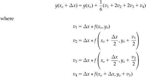 (25.30)
The fourth-order RK equations are the most popular numerical method for solving differential equations used today. Although a higher-order expansion in y would give a more accurate solution, the increased processing time required by a computer to achieve the solution is often not worth the minor improvement.
25.3 Exercises
For these exercises, begin by writing a function called ode_euler, which will implement Euler’s method to solve the sample differential equation of Equation 25.14 for x=0:0.1:10:
function f = ode_euler(x, f_o)
%This function takes two arguments, x and f_o.
%x is a vector that specifies the time points that the function f should be
%f_o is the initial condition.
%The function returns a vector, f, representing the approximate solution to the
%differential equation, df/dx=2x with f(0)=f_o.
%Set delta_x as the difference between successive x values.
%Determine how many points we need to approximate by finding the length of
%Initialize f by creating a vector of the right length. We will reset the elements to
%the correct values in the for loop below.
%Set the initial value of f to f_o.
%Use a for-loop to implementEq. 25.14
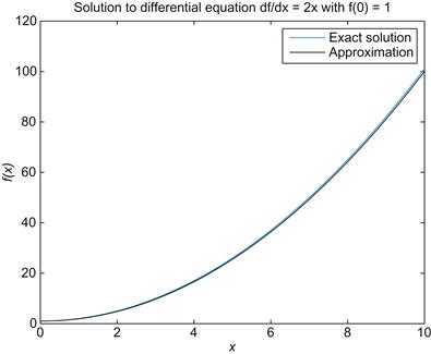
Now visualize the solution by plotting this approximation for f alongside the exact solution, f(x)=x2+1. See whether your solution looks like the one shown in Figure 25.1. Before proceeding, you should explore the relationship between the value of Δx and the validity of the approximation of Euler’s method. For example, if you plot the exact solution alongside several approximations, each with a different Δx, how quickly does the approximation cease to be reasonable? Similarly, at what point does decreasing Δx fail to provide significant improvement in the approximation despite increased run time? Basic questions such as these are important to consider whenever a numerical method is employed to approximate the solution to a differential equation.
The function ode_euler can solve only the sample differential equation of Equation 25.14 because the derivative was plugged into Euler’s method explicitly in line 24. You can generalize this function to solve any differential equation by introducing the feval() function. The feval() function evaluates functions by taking a functional handle that references the function to be evaluated and a variable number of arguments depending on the number of input arguments required by the function referenced by the function handle. As an example, consider the following command:
This line is equivalent to typing
except with the feval() function the name of the function is a variable argument, so it can be changed. To see how this can be applied to generalize the code for Euler’s method, first create another function called f_prime():
Now modify the first line of ode_euler so that it takes an additional argument, a function handle to a differential equation, and modify line 24 to use feval() to determine the value of the derivative according to the function referred to by the function handle. If everything is done correctly, then the command
should produce the same results as before feval() was introduced into the code, but now ode_euler makes no explicit reference to any particular differential equation.
25.4 Project
In this project, you will use the Euler method to derive the current kinetics for the voltage-gated potassium and sodium channels:
1. Write a function called K_v(t,V) that takes a time interval t and a holding potential V and returns the current response of a Kv channel over the time range specified by t. Hint: K_v should call ode_euler or RK4 with the inputs @n_prime, t, n_o, and V, and use the result along with Equation 25.4 to determine IK.
2. Use K_v to plot the current response of a Kv channel when the membrane potential is clamped to −30 mV. Repeat this for holding potentials from −30 mV to 50 mV in 10 mV increments, and plot the solutions on the same graph. Hint: See hold on command.
3. Write functions m_prime(t,V) and h_prime(t,V) that calculate the derivative of m and h at the point t given that the membrane potential is V. This will be completely analogous to the code for n_prime.
4. Write a function called Na_v(t,V) that takes a time interval t and a holding potential V, and returns the current response of an Nav channel over the time range specified by t. Hint: Na_v should call ode_euler or RK4 twice, once with the inputs @m_prime, t, m_o, and V and another with the inputs @h_prime, t, h_o, and V; use these results along with Equation 25.9 to determine INa.
5. Use Na_v to plot the current response of an Nav channel when the membrane potential is clamped to −30 mV. Repeat this for holding potentials from −30 mV to 50 mV in 10 mV increments, and plot the solutions on the same graph.
