This chapter looks at the engine, the cooling system and the exhaust system of the Stage 2 Land Rovers.
SECTION A: THE ENGINES
Six different engines were used in the Stage 2 Land Rovers built at Solihull; two more were used in Australian-built Stage 2 models, described in the panel on p.40.
The six ‘Solihull’ engines were 2.3-litre and 2.5-litre 4-cylinder petrol types; 2.3-litre and 2.5-litre 4-cylinder diesels; a 2.5-litre 4-cylinder turbocharged diesel; and a 3.5-litre petrol V8. All the 4-cylinder models, both petrol and diesel, shared the same overhead-valve layout, and all were derived from a design that had entered production for Land Rovers in the mid-1950s. Note that the 2.3-litre engines were generally known as 2¼-litre types until the end of the 1984 model-year; they are consistently described here as 2.3-litre types to avoid confusion.

When first introduced, the 4-cylinder petrol engine was known by its long-standing ‘2¼-litre’ name. From the start of the 1985 season it was rebranded as a 2.3-litre.
The early 4-cylinder petrol engine had a chain-driven camshaft and five main bearings.
In the early 1980s, Land Rover gradually changed from imperial to metric fixings. Most changes to the engines had taken place by late 1982, and the engines in the Stage 2 models were therefore generally built to metric standards, although there were some minor exceptions. Earlier versions of the same engines (such as suffix A 2.3-litre petrol types) typically have a mixture of imperial and metric fixings.
THE 2.3-LITRE PETROL ENGINE, 1983–1985
The 2.3-litre petrol engine was an overhead-valve engine with a cast-iron block and aluminium alloy cylinder head; the bore was 90.47mm, the stroke 88.9mm, and the swept volume 2286cc. This engine had been introduced in 1980, and was a five-bearing development of the earlier ‘two and a quarter’ type, which had the same dimensions but only three main bearings. The cylinder block of these engines was always painted Terra Cotta Red to make them easily distinguishable from the earlier three-bearing engines, which had grey cylinder blocks.
These engines were further developed for the Stage 2 models, to deliver more power and torque. However, the older versions remained in production as well, for the final Series III models, which had different identifying numbers. Power and torque outputs of the standard (8:1 compression) Stage 2 engine were 74bhp (DIN) at 4,000rpm and 120lb ft at 2,000rpm. The 2.3 litre petrol engine was suitable for fuel with an octane rating as low as 90, but it was not suitable for unleaded fuel unless modified with hardened valve seats. Probably all these engines had the Viton exhaust valve seals and polyacrylic inlet valve seals that were introduced on Series III versions in early 1983.
A 7:1 compression version of the 2.3-litre petrol engine was available as an alternative to the standard 8:1 engine, and was intended primarily for overseas territories reliant on poor-quality petrol with an octane rating of 85 or less. The different compression ratios were produced by different cylinder heads; the pistons in both types were the same. Different spark plugs were also specified.
The carburettor was a Weber 32/34DMTL type, and was new for the One Ten versions of the engine (the Series III 2¼-litre engine had a Zenith carburettor). It had twin barrels and a fixed choke, the primary barrel being used for starting, idling and initial throttle openings, and the second barrel opening progressively as wider throttle settings were required. The primary barrel incorporated an anti-run-on valve, and the secondary barrel had a high-speed jet for fast road work and maximum performance. An integral float chamber ensured that fuel was delivered to the jets regardless of the vehicle’s attitude (which was important for off-road use), and there was a spill return system to avoid vapour locks in hot conditions. There was a cyclone-type air filter with a paper element, and fuel was delivered to the carburettor by a Facet electric pump.
Early 2.3-litre engines had an oil-bath air filter, but this was changed for a paper-element filter in 1984, probably at the start of the 1985 model-year. The early engines also had an oil filter with a renewable paper element, which then gave way to a spin-on canister type. All the 2.3-litre petrol engines had an oil-filler aperture in the rocker cover, with an orange plastic screw cap.
ENGINE NUMBERS: 2.3-LITRE PETROL
The identification number was stamped into a machined surface at the front left of the engine, beside the exhaust manifold front flange. The number consisted of a three-figure type identifier prefix followed by a five-figure serial number and a suffix letter. The serial number prefixes and suffixes were as follows:
| 10H-xxxxxB |
8:1 CR, non-detoxed |
| 11H-xxxxxC |
8:1 CR, detoxed |
| 13H-xxxxxB |
7:1 CR (from 1985) |
Production Changes
Changes During 1984
From VINs 221056 (Ninety) and 221222 (One Ten), in approximately September 1984, stronger diesel-type engine-mounting rubbers were used on assembly. Later the same month, the gasket between the oil-filter adaptor and the cylinder block was modified to reduce leaks; this change, which was also made on the 2.5-litre diesel engines, was recorded as taking place at VIN 222121.
Changes during 1985
Towards the end of 2.3-litre petrol engine production, in March 1985, a new camshaft chainwheel was fitted. It had a single keyway instead of the previous six, and a wider chainwheel boss to improve clamping to the camshaft. The change took effect from engine number 11H-05232.
Oil leaks around the rear of the engine were a perennial problem, and from VIN 236411 in approximately April 1985, a PTFE crankshaft rear oil seal was introduced. This followed the introduction of a similar seal on the diesel engines a few months earlier.
Further attention was paid to curing leaks in April 1985 approximately, when the paper gasket used between the sump and block faces was replaced by Hylosill RTV sealant. The same change was made to the other engines then in production, and took effect at VIN 236624. Shortly afterwards, probably still in April 1985 and at VIN 236893, the O-ring between the flywheel housing and the rear of the engine block was replaced by an application of Loctite 574. The same change was made a month later on the other 4-cylinder engines then in production.
THE 2.5-LITRE PETROL ENGINE, 1985–1990
The 2.5-litre petrol engine was developed with the code name of Harrier and replaced the 2.3-litre type in August 1985. It was a long-stroke development of the earlier engine, retaining the original 90.47mm bore. With a 97mm stroke, this made for a swept volume of 2495cc. The engine retained the timing chain of the earlier engine and did not follow the 2.5-litre diesel (introduced around eighteen months earlier) in changing to a toothed-belt drive. The camshaft was nevertheless the same as that on the 2.5-litre diesel engine.

The enlarged 2.5-litre petrol engine had a different front cover from the earlier type, although it did not have the new toothed-belt camshaft drive.
This engine used essentially the same Weber 32/34DMTL carburettor as the 2.3-litre type but with different jets and settings to improve hot fuel handling. The carburettor also had larger internal passages, two extra cross-drillings (for improved vapour release), and new seals compatible with alcohol-content fuels. There was a new distributor with revised advance curve characteristics, and a new wire-reinforced hose between the air cleaner and carburettor had a smoother bore than earlier types. These engines probably all had the improved vertical drive-gear assembly introduced at VIN 243329 in August 1985 approximately and designed to reduce backlash. As compared to the 2.3-litre engine, power was increased by 12 per cent to 83bhp at 4,000rpm, and torque went up by 11 per cent to 133lb ft.
These engines were designed to run on lead-free petrol, and for that reason incorporated exhaust valve inserts made from sintered XW35 material. They required petrol with a minimum octane rating of 90. They had a larger bore (54mm) exhaust downpipe and intermediate exhaust pipe than the 2.3-litre types they replaced. There was no provision for a separate oil filler in the rocker cover: the push-fit breather had to be removed to top up the oil level.
ENGINE NUMBERS: 2.5-LITRE PETROL
On early engines, the identification number was stamped into a machined surface at the front left of the engine, beside the exhaust manifold front flange. From approximately January 1986, it was relocated and was stamped on to the right-hand side of the cylinder block on a horizontal face just behind the distributor. The number consisted of a three-figure type identifier prefix followed by a five-figure serial number and a suffix letter. The serial number prefixes and suffixes were as follows:
| 17H-xxxxxA |
Standard engines, 8:1 compression, detoxed |
| 18H-xxxxxA |
Military engines with 24-volt electrical system |
| 19H-xxxxxA |
For ZF automatic gearbox (unsuccessful Swiss military tender) |
Production Changes
Changes during 1986
Early in production, at engine number 17H-00050C, black PVC nitrile replaced red nitrile for the carburettor power-valve diaphragm, bringing improved resistance to fuel degradation. This change was recorded as associated with chassis serial number 242036, which would date it to September 1986.
The fuel filter changed from blue to black in October 1986, although there was no change in its specification. The same change was made on the 3.5-litre V8 petrol engines.
Changes during 1987
RTV sealant replaced the T cork seals for the rear main bearings from VIN 302667 in approximately August 1987, to improve sealing. The same change was made to the other 4-cylinder engines then in production.
The dipstick was modified with effect from VIN 304922 in approximately August 1987, as there had been some instances of fracture from vibrational fatigue. The same change was also made to the other 4-cylinder engines then in production.
Changes during 1988
With effect from engine number 17H-12321C in late summer, there was a rationalized crankshaft to suit all 4-cylinder engines. Shortly after that, at engine 17H-12883C, came stronger main bearing caps. Again, this improvement was shared with the other 4-cylinder engines then in production.
Changes during 1989
A change not reported in Service literature until November 1989 was actually made in April at chassis serial number 382469 and engine number 17H-16203C. At this point, a metric temperature sensor was introduced for all 4-cylinder engines, and the adaptor previously used between sensor and cylinder head was discontinued. It was not possible to change older engines to the new specification.
Changes during 1990
The rear crankshaft oil seal on all 4-cylinder engines was modified in August 1990, and the new seal was colour coded green. The change took place on 2.5-litre petrol engines from number 17H-19132C.
THE 2.3-LITRE DIESEL ENGINE, 1983–1984
These engines were ohv 4-cylinder types, with a 90.47mm bore, an 88.9mm stroke and a swept volume of 2286cc. The cylinder block was made of cast iron, and was painted Terra Cotta Red to distinguish it from the earlier three-bearing 2¼-litre type. The cylinder head was also made of cast iron, and there was an indirect injection system fuelled by a CAV pump driven by the camshaft. The glow plugs were 6-volt types, with a ballast resistor. The compression ratio was 23:1; power was 60bhp at 4,000rpm, and torque was 103lb ft at 1,800rpm.

The ‘2¼-litre’ diesel engine tends now to be known by its 10J prefix code to distinguish it from earlier versions in Series II, IIA and III Land Rovers. The five-bearing types always had blocks painted in Terra Cotta, as here. SCOTT ISHERWOOD
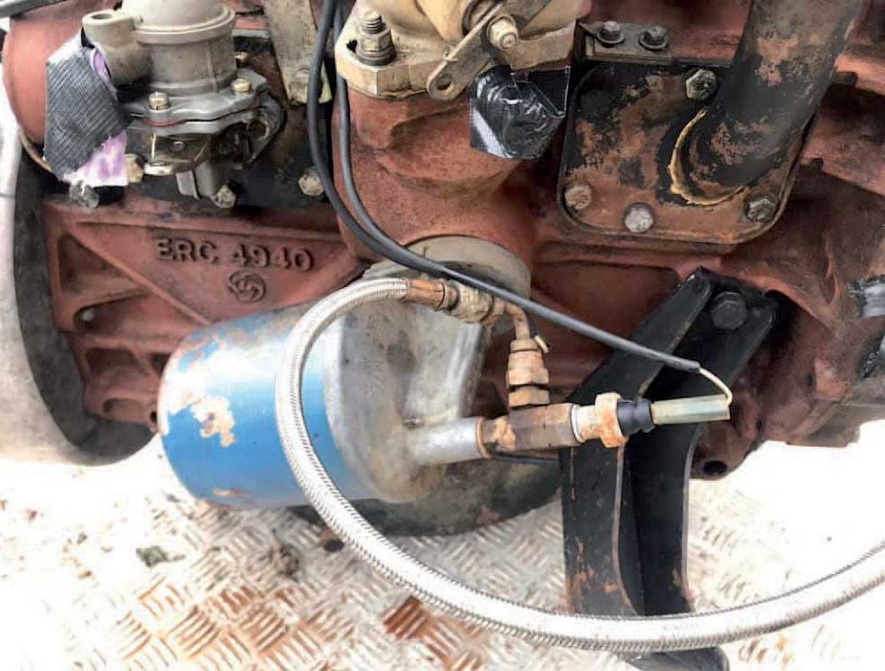
The fuel lift pump was mounted low down on the block of the 10J engines. Clearly visible here is the casting number, along with a British Leyland ‘flying wheel’ logo. SCOTT ISHERWOOD

Injectors and the fuel lift pump are seen here, together with the fuel distribution pump at top right. The fuel lines themselves are missing. SCOTT ISHERWOOD
In its five-bearing form, this ohv engine was introduced in 1980. It could trace its origins back to 1956 and the 2.0-litre diesel, and through development into the 2¼-litre diesel in 1961. The fuel lift pump was a mechanical type mounted low down on the cylinder block towards the rear of the engine, and the fuel distribution pump was a Lucas-CAV type DPA, mounted on the right of the engine.
The 2.3-litre diesel engine was used only until the summer of 1984, when it was replaced by the 2.5-litre type. There were no recorded running changes on production in that period. All production models of the Ninety had the later engine, although some prototypes and pre-production models were built with the 2.3-litre diesel engine.
ENGINE NUMBERS: 2.3-LITRE DIESEL
The identification number was stamped into a machined surface at the front left of the engine, beside the exhaust manifold front flange. The number consisted of a three-figure type identifier prefix followed by a five-figure serial number and a suffix letter. The serial number prefixes and suffixes were as follows:
| 10J-xxxxxA | Standard engines |
THE 2.5-LITRE DIESEL ENGINE, 1984–1990
The 2.5-litre diesel engine was introduced in February 1984, some eighteen months before the 2.5-litre petrol engine, with which it shared many of its improvements. It was a further development of the 2.3-litre diesel, with the same 90.47mm bore but a longer 97mm stroke and a swept volume of 2495cc. Both cylinder block and cylinder head were again cast iron, and the crankshaft ran in five main bearings. The compression ratio was 21:1, which was slightly lower than on the earlier engines.
As compared to the 2.3-litre diesel, these engines had bigger water passages in the cylinder block and cylinder head. They had a toothed-belt drive for the camshaft and the new diesel injection pump, and there was a new aluminium front housing to cover this. Unlike the 2.3-litre diesel engines, the 2.5-litre types had their cylinder bores lubricated by oil ‘jet tubes’ that were fed directly from the main oil gallery. Also of note is that the 2.5-litre diesel engines used the same camshaft as the 2.3-litre petrol engines; these camshafts were identifiable by ‘S2’ (presumably for Stage 2) stamped on the no. 8 cam lobe.
The water pump was larger than before, also with an aluminium housing. There was a compact vacuum pump for the brake servo, located where the earlier injection pump had been and driven by the camshaft. The valves had larger diameters and their ports had been redesigned, and there was a spill return fuel system. The glow plugs were 12-volt types, needing no ballast resistor. The fuel distribution pump for these engines was a Lucas-CAV type DPS.
There was a wading plug for the bottom of the front cover, with a gauze filter behind the aperture to prevent solids from entering the engine. An 82-degree thermostat was fitted, the radiator was a cross-flow type, and the air filter was a cyclone type with a paper element. Power was 67bhp at 4,000rpm, and torque was 114lb ft at 1,800rpm.

The engine bay layout around the 2.5-litre diesel engine. The fabric section of the fan cowling is clearly visible.

The 2.5-litre engines had a toothed-belt camshaft drive instead of the earlier chain-driven type. The front cover was removed for this photograph.
A version of this engine was made available for Freight Rover light commercials, but it has some important differences from the Land Rover engine. On the Freight Rover versions, the injection pump is mounted higher up and the belt drive is covered by a steel plate instead of an aluminium one. There is a permanently open vent hole at the bottom of the cover, where the Land Rover engine has a threaded hole that can be sealed by a wading plug.
Production Changes
Changes during 1984
Land Rover had a programme of chasing and rectifying oil leaks during 1984, and in September, the gasket between the oil filter adaptor and the cylinder block was modified to this end. The same change was made on the 2.3-litre petrol engines, and was recorded as taking place at VIN 222640 for the diesel engine.
A further leak problem was addressed in approximately December 1984, at VIN 226285. This time there was a new PTFE crankshaft rear oil seal, which successfully cured most of the oil leakage problems from the rear of the engine. The same seal would be introduced on the 4-cylinder petrol engines a few months later.
Changes during 1985
From engine 12J-06942 in March, new oil squirt jet adaptors were fitted. These had thicker walls for the jet tubes and a solid locating pin. During May, and beginning at VIN 237753, some diesel fuel pipes were supplied with loose olives rather than pre-formed types so they could seat better on the pipe and not leak.
Early 2.5-litre diesel engines had GKN pistons, but from 12J-12215C a change was made on production to Hepworth and Grandage M2 types. These had slight differences in skirt design, which necessitated changes to the oil squirt jet assemblies. New jets were subsequently fitted, from engine 12J-14536C.
Attention focused on curing leaks in April 1985 approximately, when the paper gasket used between the sump and block faces was replaced by Hylosill RTV sealant. The same change was made to the other engines then in production, with effect from VIN 236624. Then from VIN 240976 in June approximately, the O-ring between the flywheel housing and the rear of the engine block was replaced by an application of Loctite 574. Again, this change was also made to the other 4-cylinder engines then in production.
In approximately August 1985, at VIN 243329, an improved vertical drive gear assembly was introduced to reduce backlash. The same assembly was introduced on the 4-cylinder petrol engines at the same time.
Changes during 1986
Pistons were changed again in approximately February 1986 from engine number 12J-24326C (at chassis serial number 258000). The new pistons were Hepworth and Grandage M10 types, and were introduced to counter excessive oil consumption.
Changes during 1987
RTV sealant replaced the T cork seals for the rear main bearings from VIN 302667 in approximately August 1987, to improve sealing. The same change was made to the other 4-cylinder engines then in production.
In the same month (approximately), this time with effect from VIN 304922, the dipstick was modified, as there had been some instances of fracture from vibrational fatigue. Once again, the same change was made to the other 4-cylinder engines then in production.
Changes during 1988
A common crankshaft was introduced for all 4-cylinder engines in late summer 1988, and the first 2.5-litre diesels to have it were numbers 12J-39678C and 18J-02715C. Stronger main bearing caps followed at engine 12J-40004C, again in parallel with the same change made on other 4-cylinder engines.
Changes during 1989
The metricated temperature sensor introduced across the range in approximately April 1989 was fitted to 2.5-litre diesel engines from number 12J-43086C. As on the other 4-cylinder types, it was not possible to convert earlier engines to use it.
Changes during 1990
The modified rear crankshaft oil seal with its green colour coding was introduced at engine 12J-45804 during August, at the same time as on other 4-cylinder engines.
ENGINE NUMBERS: 2.5-LITRE DIESEL
On early engines, the identification number was stamped into a machined surface at the front left of the engine, beside the exhaust manifold front flange. From approximately January 1986, it was relocated and was stamped on to the right-hand side of the cylinder block on a horizontal face just behind the fuel lift pump. The serial number prefixes and suffixes were as follows:
| 12J-xxxxxA |
Experimental and pre-production only; Imperial fixings |
| 12J-xxxxxB |
Standard production, part metric fixings |
| 12J-xxxxxC |
Standard production, largely metric fixings |
| 18J-xxxxxC |
Military engines with 24-volt electrical system |
Note: Engines with a 15J prefix were built for Freight Rover light commercials, those with a 17J prefix for Coventry Climax vehicles, and those with a 20J and 21J prefix for the Carbodies FX4R taxi.
THE 2.5-LITRE DIESEL TURBO ENGINE, 1986–1990
Turbocharging had become a common method of getting more performance from small-capacity diesel engines in the early 1980s, and in March 1984 Land Rover felt it was necessary to warn dealers that fitting aftermarket turbochargers to Land Rover diesel engines would invalidate the engine warranty. Just over two years later, in October 1986, the company introduced its own turbocharged diesel engine. Known as the Diesel Turbo (to distinguish it from the bought-in Range Rover diesel known as a Turbo D), this was really a conversion of the existing five-bearing, 2.5-litre diesel engine.
The new engine offered 85bhp at 4,000rpm, with peak torque of 150.2lb ft at 1,800rpm. Its key feature was a Garrett T2 turbocharger giving maximum boost of 9.3psi, but the rest of the engine had been extensively re-engineered, partly to cope with the additional stresses imposed by the turbocharger, and partly to prepare it for further use in the forthcoming 200Tdi diesel engine, which would use the same cast-iron block and cylinder dimensions.

The underbonnet view of an early LHD Diesel Turbo. The high-mounted turbocharger is readily visible. PETER HOBSON

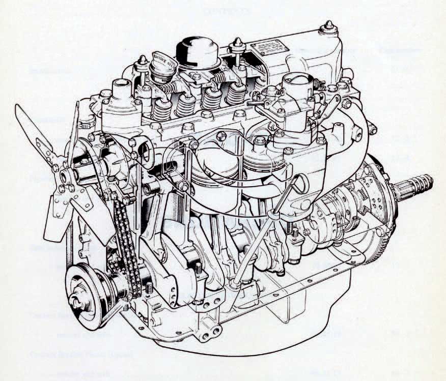
Cutaway drawing of the diesel turbo engine showing the mounting of the turbocharger in relation to other components. The cooling fan was a viscous-coupled type.

This overall view shows the diesel turbo engine with transmission attached. Clear here is the large heat shield running behind the turbocharger and down the exhaust pipe.
The block itself was modified with revised oil feed and return drillings, and there were new main-bearing shells on a crankshaft modified with cross-drilled main journals. Pistons, inlet and exhaust manifolds, and all valves were different from those in the naturally aspirated 2.5-litre diesel engine, and there was an improved crankcase breather system with a modified breather-cum-oil filler cap in the rocker cover assembly. Oil temperatures were kept steady by an engine-oil cooler (see Section B below), and there was new air ducting between an air intake on the wing and the air filter. These engines had a version of the Lucas-CAV type DPS fuel distribution pump with a manifold pressure compensator that could sense turbocharger boost pressure and ensure the injection pump supplied enough fuel while the turbocharger was operating.
Production Changes
Changes during 1987
On engines prior to 19J-00727C, a unique design of thermostat housing was fitted unless the vehicle had air conditioning. There was clearly some trouble with this, causing the engine to run hot, and in March 1987 Service literature recommended drilling an extra hole inside the housing to relieve the problem.
The spring steel clip that located the oil-feed pipe for the turbocharger on early engines could also fracture. It was replaced in February 1987 by a stainless-steel P clip and silicone rubber sleeve, at engine number 19J-03869, which corresponded to VIN 286079. Service literature recommended upgrading earlier vehicles to the new specification.
At VIN 302667, in approximately August 1987, RTV sealant replaced the earlier cork seals for the rear main bearings, to improve sealing. The same change was made to the other 4-cylinder engines then in production.
The dipstick was modified with effect from VIN 304922 (again, in approximately August 1987), as there had been some instances of fracture from vibrational fatigue. This change was also made to the other 4-cylinder engines then in production.
Changes during 1988
From VIN 322025, in approximately January 1988, an extra bolt was added to the support bracket for the turbocharger heat-shield in order to improve its fixing security.
From VIN 340422 in June, the Diesel Turbo engines were fitted with a new air-cleaner element indicator that operated at a higher depression of 76cm (30in) water, so ensuring that it did not trip prematurely. (The naturally aspirated engines meanwhile continued with the old version that operated at 59cm/22in.)
In approximately July 1988, the engine breather system was modified to minimize the risk of oil contaminating the air cleaner. There was a new breather cap, and the breather hose was re-routed from the rear of engine to the rocker cover, and was no longer connected to the breather cap. These changes took place at engine 19J-15452C, which corresponded to chassis serial number 343248.
The late summer change to a common crankshaft on all 4-cylinder engines took effect from Diesel Turbo number 19J-15480C. The subsequent introduction of stronger main bearing caps occurred at 19J-16606C.
New pistons with anodized crowns were introduced in approximately September 1988 at engine number 19J-17556C (chassis serial number 349924). The aim was to improve durability at high mileages. The second piston ring was modified at the same time, to reduce oil consumption.
Changes during 1989
In approximately April 1989, the metricated temperature sensor common to other 4-cylinder models was introduced; the start point was recorded as engine number 19J-25184C. As on the other engines, the new sensor could not be fitted to older engines retrospectively.
Changes during 1990
There were two late changes to these engines during 1990. At 19J-27515C, in approximately May, the bore for the vacuum pump housing in the cylinder block was increased, to commonize its size with that of the new 200Tdi diesel engine (then available only in the Discovery, but planned for introduction in the Defender that autumn).
The second change occurred in August 1990: this was the new crankshaft rear oil seal with green colour-coding common to all 4-cylinder engines. On the Diesel Turbo, the change was recorded as occurring at 19J-33802C.
ENGINE NUMBERS: 2.5-LITRE DIESEL TURBO
The identification number was stamped on to the right-hand side of the cylinder block on a horizontal face just behind the fuel lift pump. All engines had the same serial number prefix, and the variant suffix matched that on other diesel engines of the time:
19J-xxxxxC
Note: Engines with a 22J prefix were built for Freight Rover light commercials.
THE 3.5-LITRE V8 PETROL ENGINE, 1983–1990
The 3.5-litre V8 petrol engine started life in the General Motors Y-body compact cars of the early 1960s, and was bought by Rover in the mid-1960s. Re-engineered to suit British manufacturing methods and to meet British motoring needs, it entered production in Britain during 1967, and by the time of the Stage 2 models had become a highly respected engine that was used in Rover cars and Range Rovers as well as in the utility Land Rovers.
This was an all-aluminium alloy engine of 3528cc with a 90-degree angle between its cylinder banks and the classic arrangement of a single
central camshaft acting on overhead valves. In the Stage 2 Land Rovers, it normally had a low (8.13:1) compression ratio that was suited to low-quality fuel with a minimum octane rating of 90; the valve seats were tolerant of unleaded fuels. However, high-compression types with a 9.35:1 compression were supplied to Australia for One Tens built there from CKD kits, and these needed petrol of 96 octane or higher; if the timing was retarded by 3 degrees, they could tolerate 95-octane unleaded petrol.
The early production Stage 2 V8 engines had twin Zenith-Stromberg carburettors. In Europe and Australia, all engines were ‘detoxed’ (emissions-controlled) types with type 175CDSE carburettors; carburettor needles were type BIFK for Europe and type BIFH for Australia. On engines for territories where emissions-control equipment was not required, type CDS3 carburettors were usually fitted, with type BIFQ needles.

The early 3.5-litre V8 engines came with Stromberg carburettors; behind them is the thermostatically controlled warm-air intake. The ignition leads would originally have been black, as would the brass header tank, which is showing years of wear! This is the engine in pre-production One Ten CWK 53Y.

The serial number of a V8 engine was stamped into a pad below the left-hand exhaust manifold. This is a very early one, on CWK 53Y again.

There are few differences in this view of the V8 engine in an early Ninety, but note the presence of a reservoir for the optional power-assisted steering.

The later V8 engines had SU carburettors and a higher state of tune. This is one in a LHD model.
SU carburettors were fitted from 1986: see below. A very small number of One Tens for the unsuccessful Swiss military trials had Lucas petrol injection to meet tighter emissions requirements.
The black-painted air cleaner was mounted behind the carburettors and was quite different from the trumpetintake types fitted to Rover cars and Range Rovers. On engines destined for non-European destinations, it was an AC Delco PC26 cyclone type with replaceable paper element, and depended on a centrifuge effect to remove particles before the air entered the filter element. Air reached the main filter through a thermostatically controlled intake system, which picked up warm air when needed from a take-off on the right-hand exhaust manifold.
All V8 engines before 1988 (see below) were equipped with Pulsair air injection, which used manifold depression to draw air from the air cleaner through one-way valves and into external steel pipes running just above the exhaust ports. From here, it was drawn into the exhaust manifolds and into the exhaust stream to promote more complete combustion of the exhaust gases.
ENGINE NUMBERS: 3.5-LITRE PETROL V8
The engine identification number was stamped into a cast pad on the left-hand side of the cylinder block between numbers 3 and 5 cylinders. The serial number prefixes and suffixes were as follows:
| 14G-xxxxxA |
Standard engines, 8.13:1 compression, non-detoxed, for the LT95 gearbox |
| 15G-xxxxxA |
Standard engines, 8.13:1 compression, detoxed, for the LT95 gearbox |
| 18G-xxxxxA |
Military engines with 24-volt electrical system and LT85 gearbox |
| 19G-xxxxxA |
For Saudi Arabia, 8.13:1 compression, with the LT95 gearbox |
| 20G-xxxxxA |
Non-detoxed, 8.13:1 compression, for the LT85 gearbox |
| 21G-xxxxxA |
Detoxed; 8.13:1 compression, for the LT85 gearbox; replaced by 23G |
| 22G-xxxxxA |
9.35:1 compression, to meet Australian ADR36 regulations; from September 85 see Saudi 19G with 8.13:1 compression |
| 23G-xxxxxA |
8.13:1 compression, detoxed for Llama (prototypes only) |
| 24G-xxxxxA |
Detoxed, 8.13:1 compression; replaced 19G, 21G and 22G types |
| 31G-xxxxxA |
8.13:1 compression with injection for Swiss Army trials only, with ZF automatic and LT230T gearboxes |
Note: There were very many other variants of the 3.5-litre V8 engine, and later there were 3.9-litre and 4.2-litre sizes as well. Those listed above are the only ones known to have been used in the Stage 2 models.
Production Changes
Changes during 1985
From the very start of 1985, the cylinder-head bolts on V8 engines were coated with Loctite to improve head sealing. This procedure was recorded as starting at VIN 228793.
Attention focused on curing leaks in April 1985 approximately, when the paper gasket used between the sump and block faces was replaced by Hylosill RTV sealant. The same change was made to the other engines then in production, with effect from VIN 236624.
Changes during 1986
A major specification change was announced in October 1986, and had probably been introduced on production the previous month. SU HIF44 carburettors replaced the earlier Stromberg types, and the 1987-season engines delivered 134bhp at 4,000rpm – 20bhp more than before – although torque remained more or less unchanged with 187lb ft at 2,500rpm.
The fuel filter changed from blue to black in October 1986, although there was no change in its specification. The same change was made on the 2.5-litre 4-cylinder petrol engines.
Shortly afterwards, at VIN 280143 in approximately November, an improved tappet design was introduced. This was identified by three grooves around the tappet body.
Changes during 1987
In approximately April 1987, the V8 engines took on a new water pump with a modified seal. This was recorded as arriving at chassis serial number 292338.
Changes during 1988
From approximately February 1988, the Pulsair engines were withdrawn. Land Rover had discovered that the latest SU carburettors met emissions requirements without the additional air that was needed to make the earlier Stromberg types comply. The changeover points were recorded as chassis numbered 328517 (Ninety) and 328543 (One Ten).
A further production change was made in September 1988 at chassis serial number 349390, when a 1mm bead of Hylomar sealant was added around the water jacket holes in the inlet manifold gasket to improve sealing.
SECTION B: THE COOLING SYSTEM
The basic radiator was a cross-flow type with a three-row core. This was mounted to the chassis via rubber bushes, and was retained to the inner wing on each side at the top by a large bracket. The naturally aspirated diesel and V8 models used a different radiator, which was also available as a heavy-duty option on 4-cylinder petrol models. The Diesel Turbo models had yet another design of radiator with a four-row core and an oil cooler mounted inside the right-hand end tank.
Radiator hoses differed between the 2.3-litre and 2.5-litre engines, those on the larger capacity engines supposedly being of heavier duty construction. From VIN 257177 in approximately February 1986, the bottom radiator hose on V8 models was modified. The expansion tanks differed between the 4-cylinder and V8 models, and the hose between the radiator and the expansion tank on diesel models was different from the one on petrol models.
4-cylinder engines had a three-piece fan cowl, with one section attached to the radiator and one mounted close to the fan, the two metal elements being joined by a section of fabric ducting. There were differences between the petrol and diesel types. The Diesel Turbo engines had a different one-piece moulded fan cowl, and the V8 engines also had their own type of cowl; neither of these types had the ducting characteristic of the other engines.
An 82-degree thermostat was standard with all engines except V8s for the Australian market, which had an 88-degree thermostat.

There were multiple different fan arrangements (see table on p.40).
THE ISUZU DIESEL ENGINES
Demand for a large-capacity diesel engine in Australia prompted the local assembly plant to standardize on a 3.9-litre 4-cylinder Isuzu 4BD1 engine for its One Ten models. These were only sold on the domestic market and were badged as 3.9D types. From 1986, a less powerful version of this engine was fitted to all the military One Ten 4×4 models supplied to the Australian Defence Force under the Perentie contract.

The naturally aspirated Isuzu diesel engine, seen here in an Australian-built 120-inch model. PATRICK BROWN

There was a turbocharged version of the Isuzu diesel as well, seen here in one of the Australian Defence Force’s 6×6 long-distance patrol vehicles.
The 4BD1 was a cast-iron engine with a swept volume of 3856cc, a bore of 102mm and stroke of 118mm. In civilian guise it had 97bhp at 3,200rpm with peak torque of 188lb ft at 1,900rpm. Military versions were rated at 88.5bhp and 180lb ft at the same engine speeds.
A turbocharged version of this engine, known as the 4BD1T, was used in the Australian Perentie 6×6 military models from 1986, and later also in 6×6 Land Rovers for the civilian market in Australia. The bore and stroke dimensions of this engine were the same as those of the naturally aspirated 4BD1; power was 121bhp at 3,000rpm and peak torque was 231lb ft at 2,200rpm.
The Isuzu engines used a completely different identification system to the Land Rover one. Full details of running modifications made during production are not currently available.
Production Changes
Changes during 1985
With effect from chassis number 245447 in September 1985, all radiators had silver-soldered joints on their inlet and outlet pipes, which both strengthened the assembly and increased component life.
Changes during 1987
There were no recorded changes to the cooling system during 1986.
In approximately February 1987, with effect from chassis serial number 285385, the pipe adaptor fitted to the oil cooler radiator on Diesel Turbo models was replaced by an adaptor with a tapered thread to improve sealing. In mid-1987, all models except the Diesel Turbo were given new radiators with thicker-walled end tanks that had an additional stiffening swage and reinforced plates.
Changes during 1989
There were no recorded changes to the cooling system during 1988. In March 1989, the Diesel Turbo models then gained a new radiator with loop-type expansion joints where the framework joined the end tanks top and bottom. The purpose of this was to relieve thermal stresses and prevent leaks.
A further change was made in June, when the radiator with oil cooler (as used on the Diesel Turbo) was made standard on models with the naturally aspirated diesel engine as well.
SECTION C: THE EXHAUST SYSTEM
The exhaust system inevitably differed from model to model, the differences beginning at the downpipe from the manifold, where 4-cylinder models had a single pipe while the V8s had a Y-shaped assembly to suit their twin manifolds. There was then an intermediate pipe, longer on the One Ten than on the Ninety in all cases, a centre exhaust silencer, and a rear silencer with single tailpipe that emerged on the left of the vehicle’s tail. On the One Ten Crew Cab and One Two Seven models, a flanged extension in an otherwise standard One Ten system took up the difference in length.
Intermediate pipes on the 2.5-litre models had a larger bore than on their 2.3-litre predecessors, and the Diesel Turbo models had their own system with straight-through silencers, a resin-injected one-piece heat shield over the top of the down pipe, and an additional heat shield under the floor.
There were some running changes during production.
Production Changes
Changes during 1985
Several modifications were made during 1985 to reduce the transmission of engine-bay heat into the cab, and the first of these was the addition of exhaust heat shields at VIN 237572 in approximately May.
Changes during 1987
There were minor changes to the tailpipe location at the beginning of the year, to deal with noise caused when the pipe hit the chassis or the mudflap bracket. The change took place first on One Tens at VIN 283339 in approximately January, and the Ninety followed at VIN 285479 in approximately February. On the One Tens, the mudflap bracket was also moved forwards by 30mm (1in).
Then at VIN 291579 in approximately April, the 4-cylinder petrol and naturally aspirated diesel engines gained a revised downpipe with strengthened flange at the manifold joint, and an additional mounting to the engine block. This redesigned pipe could be retro-fitted to earlier engines.
Changes during 1988
From VIN 356038 in approximately November 1988, there were new downpipes for the petrol 4-cylinder and naturally aspirated diesel engines. These had a machined sleeve at the manifold end, welded to the pipe to improve strength, and a loose flange to suit. These new arrangements eliminated the need for the support bracket assembly introduced on the exhausts for these engines in April 1987.