N0 7
WELDING IRON
Strong & light
Welding is not usually a technology you would associate with the garden. However, welding will create many more possibilities for your garden projects. Where you had previously weaved wires together to make plant supports, with welding you can now make stable constructions in all shapes and sizes. I learned how to weld over a couple of months at an evening course.

The Golden Gate Bridge in California, a famous suspension bridge, was opened 1937. At that time it was the world’s longest bridge. Its unique structure and characteristic red-orange color make it to stand out. Steel was manufactured on the East Coast and transported by train and boat to San Francisco, where it was then assembled. 2 m-thick and 2.3-kilometer-long cables support the bridge. The towers measure 227 m above sea level.
There are many ways to put together metal materials. One of these ways is welding. Metal pieces are heated up and fused together. The energy required to melt the materials is generated in different ways, using to different welding techniques. Advanced techniques make it possible to weld underwater and in space, and simpler techniques can be used for industrial welding, as well as welding in the garden. In arc welding, the materials should be free from dirt and oxides and the welding electrode should have a low moisture content to make a satisfactory weld.

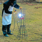
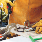
This is the equipment you need to weld in the garden—a welder with an electrode and grounding conductor, a welding helmet, gloves, and a leather apron.
My Introduction to Welding
Welding is my most recently acquired skill. An advertisement for an evening course in my municipality sparked my interest. Although I had never had the equipment or basic skills to weld, I was curious to learn. For a few hours every week for the next few months, I gained a taste of welding. Now, I have acquired a small welder, and I weld plant supports and simple structures for the garden.
Arc Welding
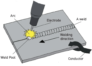
I have a simple arc welder. The real name of the technology is metal arc welding, MMA (Manual Metal Arc). It’s a simple but relatively slow welding method. The equipment consists of a power source, a welding cable with an electrode holder, and a return conductor. The electrode consists of core wires and a sheath. When welding, an arc of light appears between the electrode and the work piece by an electrical short. The arc makes the metal pieces melt. Among other things, the job of the electrode’s cover is to produce protective dross.
In order to form an arc between the electrode and the goods, the grounding conductor has to be connected to what is to be welded.

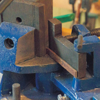
A magnetic holder keeps the parts in place in a 90-degree angle and is an excellent support when welding.
Other Arc Welding Methods
Because it takes time to change the electrode and tap the dross, new welding methods have been developed where the wire is fed by a machine and a gas atmosphere protects the arc. The difference between MIG welding (Metal Inert Gas) and MAG welding (Metal Active Gas) is the gas or the gas mixture that is used. The equipment for MIG/MAG is more extensive and is used mainly by welding professionals in the industry.
Another high quality welding method used in the welding industry is TIG welding (Tungsten Inert Gas).
Spec drawing of a weld.
Risks and Quality Requirements
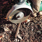
When welding, a flame with a very high temperature that can ignite most materials produced. Glowing spatter is dangerous, as are the “black” welding sparks, which may have a temperature of up to 500°C.
The noxious fumes contain a mixture of gases and metallic particles that evaporate from the hot arc and the melted metal.
Another risk with welding is the intense UV and IR radiation that is generated. Radiation is extremely harmful to your eyes and skin.
If you are you interested in welding you should definitely begin by attending a welding course. A simpler way is to enlist the help of a steel and welding company. You can decide what kind of iron and steel work you want and employ a company to do the welding itself.

The world’s most famous steel structure is probably the Eiffel Tower, which was built for the World Exhibition in Paris in 1889. The 300 m-high tower was the world’s tallest building for more than 40 years and is one of truss technology’s masterpieces. Two and a half million rivets join various parts. Riveting was the dominant bonding method when the tower was built. In the early 1900s, welding was developed and the foundation of modern steel construction was created.
SAFETY
Welding is extremely flammable and must be handled accordingly. Ensure that sparks do not ignite other materials.
• A welding shield or welding helmet is mandatory. The intense ultraviolet radiation is harmful to the eyes.
• Wear heavy work gloves and a leather welding apron to protect your skin from radiation and sparks.
• Weld in an area with adequate ventilation so that you will not breathe in the unhealthy welding fumes.
• Work gloves, safety glasses, and hearing protection are required when cutting with an angle grinder.
Walking through a fragrant rose arc or a door standing ajar is enticing. It frames the garden and gives it a lift. A softly rounded Moorish arch, which can be seen in the Great Mosque of Córdoba or in the magnificent Alhambra Palace outside Granada in Spain, creates a beautiful shape. An easy way to bring Moorish architecture into your garden is to bend rebars. Our slender Mooresque vault frames the Greek urn which sits on top of a stone (see p 143). An alternative to welding the iron rods is to wrap them together with lashing wire.
MATERIALS
• 1 sheet of plywood (10 x 750 x 1350 mm)
• 6 rebar 6 m (10 mm)
• Masking tape
• 1.5 m rebar (8 mm)
• 5 m strip of wood (30 mm wide)
• 12 small nails
• 1 piece of masonite (1 x 1 m)
• 12 m lashing wire
TOOLS
• Ruler
• Awl
• String (1 m)
• Scissors
• Jigsaw
• Tape measure
• 5 fast wings or clamps
• 1 long screw clamp (90 cm)
• 2 pipes 2 m (inner diameter 12.7 mm)
• Angle grinder or bolt cutters
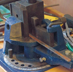
• Bending machine or vise and pipe wrench
• Hammer
• 2.5 m elastic rope
• Spirit level
• Straightener
• Wire cutters
• Self-locking welding clamp
• Welding equipment; e.g. stud weld
• Wire brush
• Chipping hammer
STEP BY STEP
The vault is 90 cm-wide. Aligning several arches in a row will create an airy pathway. Arches can be dressed with annual climbers.
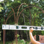
1 Draw two circles on the plywood board with diameters of 60 cm and 72 cm (see page 230). The cord loops need to be 30 cm and 36 cm long. Cut out the templates. They are needed to bend the arcs.
2 Make a datum point on the large template’s periphery. Measure 1 m in each direction along the template’s edge and make a new mark. The iron should be bent in this direction. In the same way, mark 70.7 cm from the datum mark on the small template.

3 Mark the center of the rebars with tape. Also mark how far the irons should be bent. Put a piece of tape 1 m in each direction on two irons and 70.7 cm on four irons.

4 Place the small circular template and one of the accompanying rebars on a workbench. Secure the midpoint of the rebar against the datum point on the template’s periphery with clamps.

5 Secure the circular template to the workbench with clamps so that it sits firmly.

6 Put the iron pipes on the rebar’s ends to meet the outer tape marks. Hold the iron pipes and begin to bend the iron around the template.

7 Bend the iron smoothly around the template’s edge so that the markings on the iron reach the marks on the template.
8 Let go of the iron pipes. The rebar will then open up so that a semicircle with a diameter of 90 cm forms.
9 Loosen the clamps and remove the pre-bent iron. Bend the other three rebars in the same way and with the same template.

10 Bend the remaining two rebars after the great circle’s template. Place the six bent bars on the lawn. There should be 17.5 cm between the small and the large arches.
11 Cut the small arcs to the same length as the big iron arches’ lower edges. Put a tape mark 20 cm from the bottom on each rebar.

12 Cut twelve 12 cm-long pieces of rebar that are 8 mm in diameter. Bend the pieces at a 90-degree angle in a bending machine, or with a pipe wrench when they are secured in a vise.

13 Assemble the iron arcs into a vault. Put the small arcs in an exterior square, and the large arcs should sit like an internal cross. Push the rebars gently into the ground. They should sit 3 cm away from each other. See also the sketch below.
14 Nail together simple 30 mm-wide spacers to a cross. Put the spacing pieces between the irons, 5 cm above the ground marks. Keep the irons together with elastic rope.

15 Fasten a framework of 30 mm-wide strips between the irons so that they are positioned at the right distance from each other. Check regularly that the irons are straight with a spirit level.

16 Cut out a 5 x 5 cm square from each corner on the masonite sheet. Place the masonite on the bars. Nudge the irons’ placement so that they are firmly against the recesses. The masonite disc holds the irons parallel and at the right distance.
17 Tie the three rebars to three iron angles in each corner of the frame with the lashing wire. Put the angles 50 cm, 115 cm, and 180 cm above the ground marks.

18 Grip one iron at a time and push it down into the ground. Do a little at a time and alternating between the different irons. The tape marks show how far down the irons should go.
19 Measure both horizontally and vertically so that the vault is straight.

20 Remove the lashing wire tie and weld the brackets with the angles. Tap off the slag and check the welds. Plant a climbing plant in each corner to cover the arch in greenery.
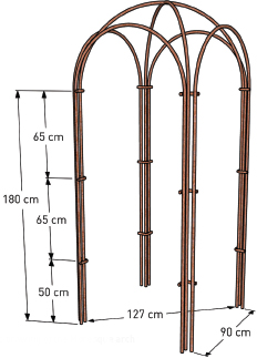
Spec drawing of the Moresque arch
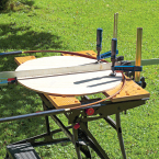
FLOATING TABLE
Our white-painted, cast-iron furniture from Byarum is a favorite in the garden with its beautiful, classical forms. Since it is heavy to move, it has gained a permanent place of honor on the lawn under the old apple tree. Small and light furniture is also needed in the garden. As a point of contrast, a small, light floating table made of slate and iron will be an exciting feature in the garden. To move the table, simply detach it from its hanging chain.
MATERIALS
• 1 slate tile (40 x 40 cm)
• 1 piece of plywood (35 x 35 cm)
• 1 round steel rod 2.3 m (8 mm)
• 1 heavy chain for suspension
TOOLS
• Tape measure
• Large calipers or pen and string
• Angle with cutting disc for stone
• Jigsaw
• Bolt cutter
• 2 iron pipes 1 m (inner diameter approx. 10 mm)
• 3 clamps
• 1 long screw clamp (40 cm)
• Drill
• Hole saw (41 mm)
• Bending machine or vise and pipe wrench
• Welder, e.g. a stud welder
• Chipping hammer
PLANTS
• Large flowered climber rose, Rosa ‘Ilse Krohn Superior’
STEP BY STEP
The big hook for the floating table can be easily made in a bending machine. If you do not have access to one, you can fasten the iron in a vise and bend it with a pipe wrench.
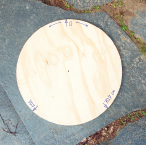
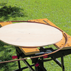
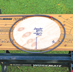
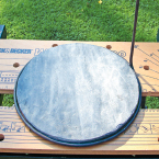
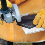
1 Draw a circle on the slate tile that is 35 cm in diameter (see page 230). Cut the circle with an angle grinder.

2 Draw and cut a circle of 31.5 cm in diameter from the plywood board. The round bar should be bent with a length of 113 cm so that it makes one lap around the template with a remaining length of 14 cm. Mark the starting point on the circumference of the circle. Measure 14 cm from the starting point. Mark the end point.

3 Fasten the circle template with clamps along the workbench’s edge. Cut a 1.8 m-long round bar, mark the 113 cm-point with tape. Insert the rod into the two iron pipes and place it along the edge of the table.

4 Fasten the rod at the tape mark. Use the iron pipes as handles. Start by bending the rod’s long part gently around the template. Release the screw clamps, and advance the rod a little bit before it is clamped and bent further.

5 Drill three holes in the bending template when you have come so far so that the iron pipe is no longer to be used as a handle. Put clamps in the holes and fasten the rod to the template edge with clamps so that the rod end also bends.
6 Remove the rod from the bending template when the rod has been bent all the way to the final mark at 113 cm. The rod then opens and forms a circle 35 cm in diameter.
7 Bend the remaining iron rod at a 90-degree angle to become the suspension bar. Try the slate in the iron ring to ensure that it fits. Otherwise, adjust by pressing together or pulling the iron ring open.

8 Bend a nice round hook with a diameter of 7 cm at the end of the suspension rod. This is most easily done in a bending machine.

9 Weld two round bars onto the bottom of the ring that is holding the slate. Put them 20 cm apart from each other. Weld the ring to the bent suspension rod.

10 Bend the rod so that the hook is centered over the table. Add the slate and hang the table in a heavy chain. Check that it hangs horizontally. Otherwise, adjust the angle of the rod.
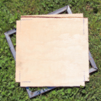
PEDESTAL STAND
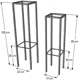
When raised above ground level and placed on a pedestal, a plant can become even more striking. Here, I have combined my two favorite materials, metal and concrete. This simple steel frame is made to fit the concrete slab with lace on page 69. The pedestal is charming and stylish, and it is stable enough to withstand strong winds. If you leave the steel untreated, it will begin to rust, giving the steel a natural, discreet appearance in the middle of the garden.
Other Pedestal Slabs
You can use the stand for pedestal slabs made using materials or methods. However, always make sure that the disc has four 8 mm-thick dowel pins. For the small stand, the pins are positioned with a c/c (ie, center to center) distance of 20.5 cm. For the larger stand, use a c/c distance of 23.5 cm.
MATERIALS
For the stand supporting a small pedestal slab (29 x 29 cm) on page 69.
• 4.2 m precision square steel tubes (15 x 15 x 1.5 mm)
• 80 cm round steel rod (8 mm)
• One piece of plywood (22 x 22 cm)
TOOLS
• Ruler
• Hacksaw
• Metal file
• Cord
• Quick clamps
• Welding aggregates, e.g. stud welding
• Wire brush
• Chipping hammer
• Magnetic holders
STEP BY STEP
The following describes how to make a small steel frame that will support a disc with the dimensions 29 x 29 cm. The sketch here also shows the large frame that supports a disc with the dimensions 33 x 33 cm. Both discs are manufactured in the same way but the larger one requires a 4.9 m steel tube, a 90 cm rod, and a piece of plywood that is 25 x 25 cm.
Spec drawing for a large and small pedestal stand

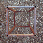
1 Cut the pedestal legs from the square steel tubes. The legs should be 85 cm long. Put the pedestal disc upside down and slide the tubes onto the disc’s pins. Then cut the frame pieces to be about 19 cm long. Measure the distance between the legs before the frame pieces are cut.
2 Make a template from the plywood board. Cut out 1.5 x 1.5 cm pieces for the legs in each corner. The template is used to keep the legs parallel when welding. Put the disc between the bottom of the legs and tie the legs together with a string.

3 Keep the pedestal’s legs together with clamps if they feel unsteady. A magnetic holder helps to keep the portions at a 90-degree angle. Brush off any rust with a wire brush and weld the frame parts to the legs.

4 Tap off the slag and check the welds.

5 Cut 4 x 19 cm long pieces of rod. Weld a rod between each pair of legs, 30 cm from the bottom of the hem.
6 Righten the pedestal stand and place it on a firm surface.

7 Place the concrete slab on top and fit it into the corner holes in the legs. With the slab in place, the pedestal is finished.
DECORATIVE TREE TRUNK PROTECTION
Anyone who has a garden knows it’s not only humans who enjoy plants. Deer unashamedly eat flowers and rub their antlers against young shrubs and trees. Magnolia, cherry, and Euonymus are plants that are particularly attractive to the deer. When you plant a new tree, you should take measures to protect it to allow it to grow unharmed. I welded a protective fence for my newly planted tree, which also helps shape the tree as it grows. The fence is made in two halves that fit together with a simple steel loop over an adjacent brace.
Give the Bushes Some Space
Animals go after trees and shrubs alike. Often, shrubs that are attacked by animals perish before they have the chance to mature and flourish. For shrubs, use the same technique in welding the tree trunk protector, but adapt its shape to the bushes.
Prunus cerasifera
MATERIALS
• 12.6 m steel rod (6 mm)
• 2.4 m flat steel bar (12 x 3 mm)
• 1 steel chain with at least two links (internal dimensions approx. 7 x 14 mm) or 20 cm lashing wire
TOOLS
• Ruler
• Bolt cutter
• Bending machine
• 4 small clamps
• Welding aggregate, e.g. stud welding
• Wire brush
• Chipping hammer
PLANTS
• Cherry plums, Prunus cerasifera
STEP BY STEP
This trunk protector is suitable for a small ornamental tree where the crown branches begin at an approximate height of 70 cm. If your tree has a taller trunk, make the round bars longer to fit the tree.
1 Cut the round rod and flat rod with a bolt cutter. For the trunk protector the following materials are needed:
• 8 round bars at 1.2 m
• 6 round rods of 0.5 m
• 4 flats of 0.3 m
• 2 flats of 0.6 m
2 First, bend the long round bars for the standing portion of the trunk protector at a 10-degree angle, 50 cm from the edge. Then bend the short flat bars at an angle of 60 degrees, 10 cm in from each edge as shown.
3 To make the long flat bars tight against the standing portion, they must first be bent at a 10-degree angle, 20 cm from each edge as illustrated. Then, bend the rods at a 60-degree angle at the same place, but standing as shown in the previous image.
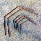
4 The six bent flat bars are completed. They will be the horizontal supports at the base of the trunk protector.
5 Place two of the small bent flat bars against each other on the lawn. Insert the eight long round bars in the soil as illustrated.

6 Angle the rods so that they stand straight and are symmetrically distributed. Adjust the height so that their angles are equal.

7 Fasten the other two small flat rods with clamps just below the bend.

8 Weld the upper part of the flat rods against the four rods on each half of the trunk protector.
9 Tap regularly to remove the slag with a slag hammer and check the welds.

10 Weld the two upper flat rods 10 cm from the top. Also weld the six short standing round bars between each rod so that the upper part of the protector becomes denser (see diagram to the right).
11 Turn the trunk protector upside down. Attach the lower small flat rods, 30 cm from the protector’s bottom and weld them.

12 The two halves of the trunk protector are completed.
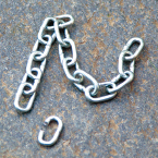
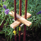
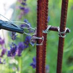
13 Cut off two links from the chain with a bolt cutter. The loose links become a stylish and simple lock to the trunk protector.

14 Plant the plum tree. The flowers have pink petals with dark red leaves. Hardy to zone 3.

15 Insert one side of the trunk protector on each side of the trunk so that the outer legs are touching each other. Attach the halves to each other by threading the chain links over the adjacent bars.

Spec drawing of the trunk protector made in two equal parts. It is denser at the top so that the deer is not able to push his nose between the bars.
OUTDOOR CANDLE HOLDER
What is warmer and more welcoming than torches burning at dusk, during the dark winter? You could even place several of them in a row to light up the pathway and the entrance. To protect the grass, it is good to elevate the candles. For this, the holders should stand steady without falling over. Filling the holder with sauna stones helps to stabilize it and give it charm. When not being used for candles, the holder can support a hanging potted fuchsia.
Fold a Pentagon
Start with a strip of paper that is 85.6 mm wide and 680 mm long. Make a simple knot in the middle of the paper strip. Pull the strip tight so that it does not have gaps in the corners. Press the lines of the paper so that it forms discernible edges. Fold in the two bits that stick out and the pentagon is completed.

Polygon
MATERIALS
• 4.9 m square bar of steel (8 x 8 mm)
• 2.8 m reinforcing steel Bi40
• 1 sheet of iron (5.5 x 146 x 280 mm)
• 6 liters of decorative stone (50/120)
TOOLS
• Compasses
• Ruler
• Scissors
• Ruler
• Angle grinder with cutting wheel for metal
• Metal file
• 3 welding tongs, type C-clamp
• Welding aggregate, such as stud welding
• Wire brush
• Chipping hammer
• Bolt cutter
• Magnetic holders
STEP BY STEP
The candle holder is built with two iron plates with five corners that lie on a frame. Be sure to measure the frame parts so that it forms a regular pentagon.
1 Draw a pentagon with 9 cm-long sides on a piece of paper (see below and to the right). Cut and draw 2 pentagons on the iron plate.

2 Cut out the pentagons with an angle grinder. One plate should be the base and the second the top piece. Sand any sharp edges with a metal file.

3 Draw a pentagon on the welding surface. It must be 4 mm larger all around compared to the cut out pentagon. This will be the template for the base frame.

4 The frame is built from a square bar. Cut the rod into five 96 mm-long pieces with angled cuts. For a perfect pentagon the angles should be 54 degrees each (see sketch above), but it is also possible to cut freehand with angles around 45 degrees, and to fill the gap with a weld joint. Cut one piece at a time and check the fit against the template (step 6) before the next piece is cut.

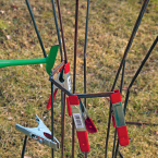
5 Align the frame pieces, one by one, to the template on the welding surface. The template shows the frame’s outer edge. Adjust the pieces with the grinder if they do not fit. Fasten the frame pieces to the base with welding tongs so that they lay still.
6 Weld the frame. Remove any slag with a hammer and check the welds. Make another frame in the same way.

7 Fasten one framework on top of one of the pentagons and weld the frame and plate together. Now the frame is attached to the base plate.
8 Cut off some of the corners on the base plate frame so an 8 mm-wide and straight edge is formed. Cut the square bar for the legs in 5 pieces that are 65 cm long. Grind off sharp edges with a metal file.

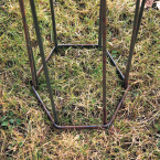
9 Put a square leg against one of the trimmed corners of the bottom plate frame. The frame should be facing down and the leg should stick out 20 cm below the bottom plate. Hold the leg with a magnetic holder. Weld the leg to the frame. Do the same with the other four legs.
10 Weld all five legs to the upper frame. It should be 7.5 cm below the square rods’ top edge.

11 Cut the rebars into five 50 cm-long pieces. The protruding parts of the steel rods should be 7.5 cm on one side and 5 cm on the other side.

12 Lastly, weld the rebar to the frames in the center of the pentagon’s sides. The top of the reinforcement steel should be level with the top of the square legs.

13 Press the candle holder into the ground and fill it with stones. Finally, place the top plate on the top frame. Now the candleholder is ready. Enjoy!

Spec drawing of the candle holder. The upper plate is removable so that the holder can be filled with decorative stones.
Make a Perfect Pentagon
The proper name of an equiangular and equilateral pentagon is a regular convex pentagon. You can draw it geometrically. My pentagon is designed to be 10.4 cm in diameter, according to the size of my candle
The size of the pentagon is designed so that there is a 1 cm-space around the candle. The pentagon’s sides become 9 cm long.
To do this:

1. Draw a circle with a radius of 76.5 mm.

2. Set the compass so that the radius becomes 90 mm. Place the compass needle somewhere on the initial circumference of the circle. This will be called point A and it will become one of corners in the pentagon. Draw a line that crosses the circumference of the original circle, point B. It will be the pentagon’s second corner.

3. Move the compass’ needle to point B and draw a new line that intersects the circumference of the original circle and creates point C.

4. Repeat until all five corners are marked.

5. Draw a straight line between two adjacent corner points, e.g. A–B.

6. Repeat for all neighboring vertices, and the pentagon is ready.