Chapter 3. Clamping, Joining, and Measurement
Although hand and power tools give us the means to construct and deconstruct, the tasks that they tackle are supported by a wide range of clamps, fasteners, adhesives, and measurement tools. Each category of support tool makes it possible for work to be conducted in a more secure and safe manner. They are mechanically and chemically bonded, and checked for accuracy.
Clamps and Vises
Clamps and vises provide a temporary mechanical bond between two or more materials and are widely used during the construction of a project. These tools feature robust and unique designs that can secure objects and materials at almost any angle, making the construction process easier to accomplish. Every Makerspace should offer a wide range of clamps and vises to ensure the proper construction of its ongoing projects.
Clamps
Clamps provide a compressive force to secure one or more objects in place while work proceeds on them. Regardless of design, clamps are meant to function only as a temporary support mechanism and should be removed prior to project operation.
The common clamp features are identified as follows:
Clamp Types
- Bar
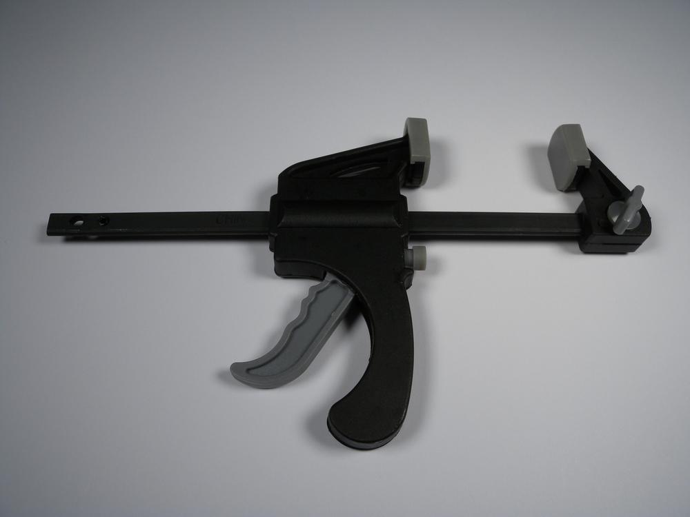
- Bar clamps are designed to compress materials over a wide range of thicknesses (Figure 3-1). These clamps feature a sliding head that can be quickly positioned into place and compressed with a trigger. To release the clamp, simply press the release button and slide open the jaws.
- C-clamps
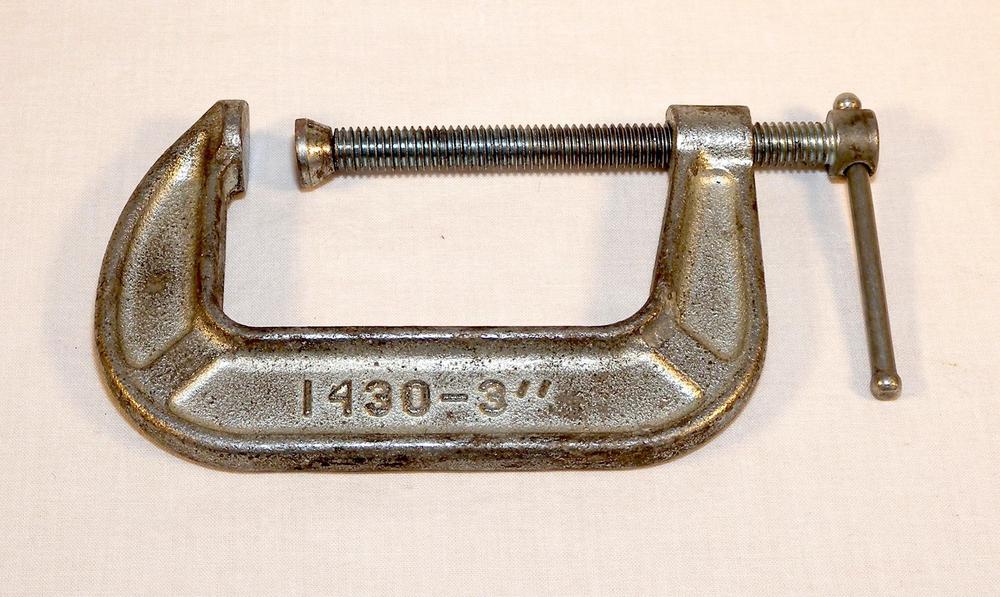
- C-clamps are the most utilitarian type of clamp due to their ease of use and clamping power (Figure 3-2). The clamp consists of a C-shaped body with a threaded hand screw. There is usually a swivel foot attached to the base of the screw that helps to prevent the clamp from “walking” while it’s being tightened.
- Spring
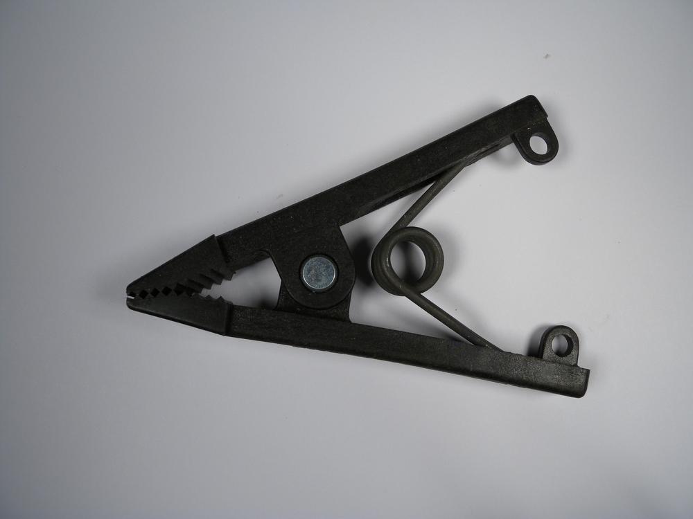
- Spring clamps are the quintessential temporary clamp (Figure 3-3). Similar in operation to binder-clip clamps, these devices secure material through compression produced by an internal spring. They are great for flattening and straightening thin material or for temporarily securing light materials in place.
- General Clamp Use
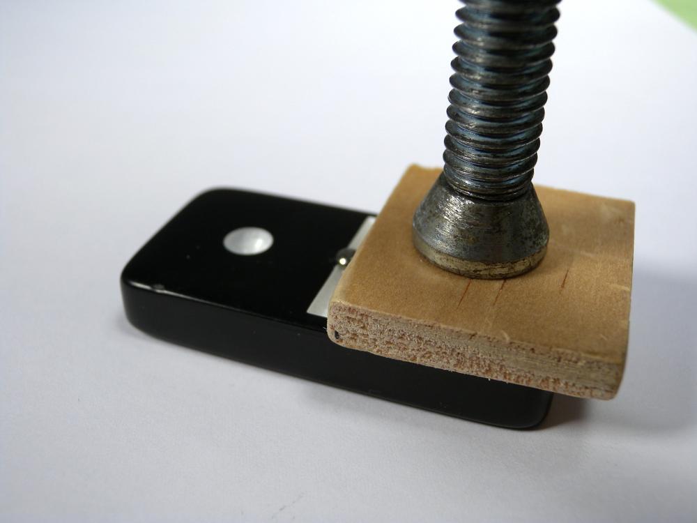
- You can use clamps by positioning one or more pieces of material in the opening and compressing the clamping mechanism. The amount of compressive force depends on the clamp type and application. When using a clamp on soft materials or those with a sensitive surface finish, place a wood block between the material and the clamp’s feet (Figure 3-4). This way, the clamp can compress the material without marring the surface.
Vises
Vises operate by using a screw mechanism to compress and secure objects and materials in their jaws. You can use these tools to secure material that you can then work on by hand or machine, making them an important addition to any Makerspace.
- Base
- The base of the vise is the stationary component that is mechanically coupled to the work surface (such as a drill press table). Bases often include special mounting features that facilitate easy mounting. Avoid using vises that are mounted by using a C-clamp-style mechanism. These have the tendency to shift while working and can damage the work surface.
- Jaw
- A vise’s jaws consist of two pieces: the first is attached directly to the base and does not move; the second is attached to the screw mechanism and you can compress and retract it by rotating the vise’s handle. Some jaws include special cutouts that are designed to align and hold round objects. These features are helpful when attempting to drill a round object or hold it in place while cutting.
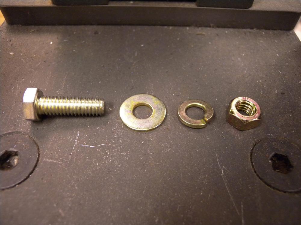
When installing a vise on a work surface, use bolts rather than screws. Pass the bolt through the base of the vise and secure it in place with a washer, lock washer, nut combination. This setup will help prevent the vise from shifting over time.
Vise Types
- Bench
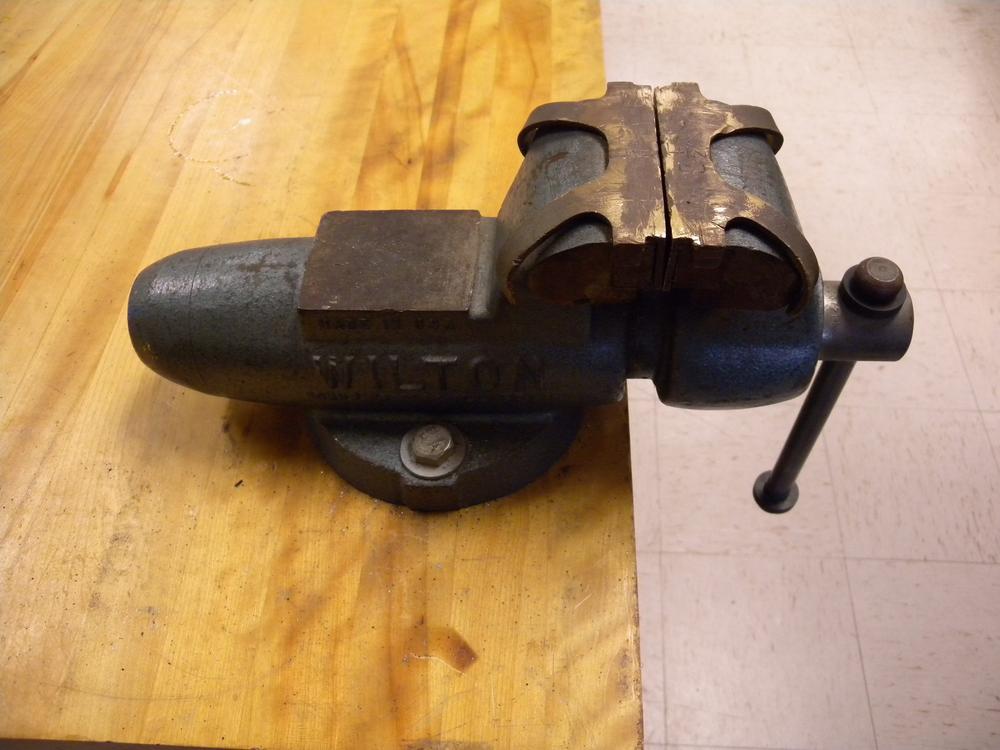
- Bench vises are designed to mechanically couple to a work surface and provide a robust method for securing material on which you need to work (Figure 3-5). You should install a vise at the height of the average person’s bent elbow. This positioning helps reduce fatigue when being used. Bench vises feature a large set of jaws that are compressed by turning the handle. When not in use, make sure the handle points down, reducing the risk of someone walking into the outstretched handle.
- Table
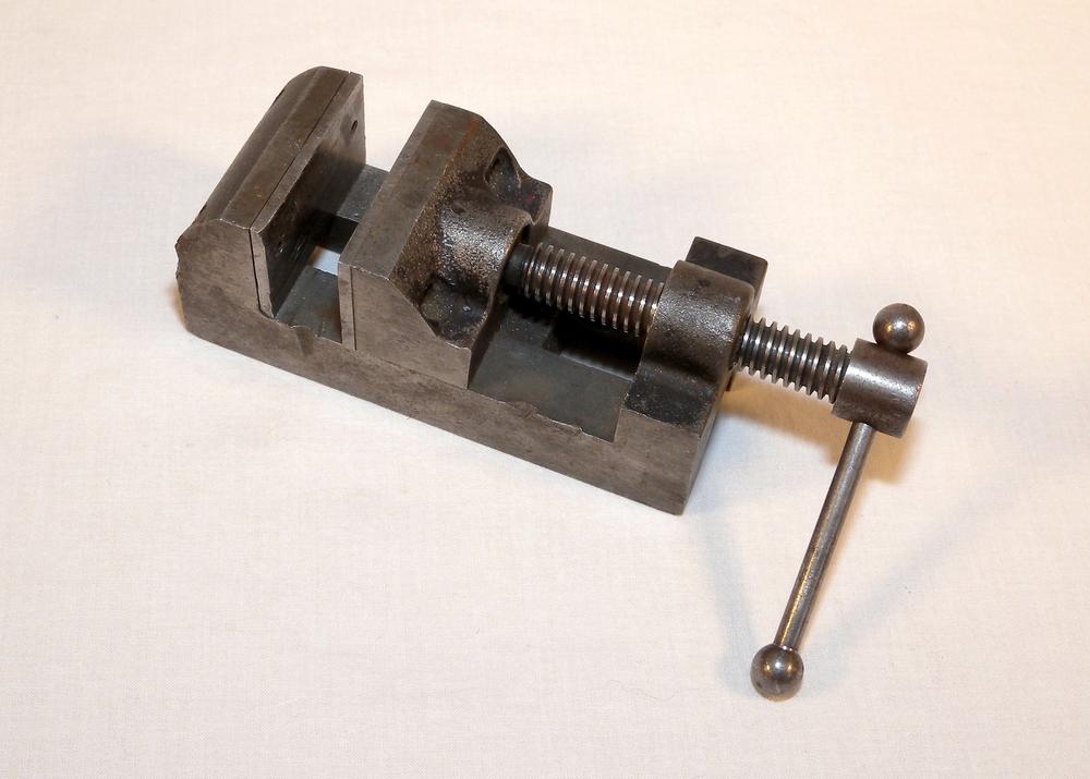
- The table vise is designed to secure small and complex material in place while being drilled (Figure 3-6). This vice features a wide base and bolt mounts that can be used to both clamp and bolt the vise to the drill press table. Ensure that the vise is securely mounted to the table. This prevents the vice from becoming a projectile if the drill bit catches while drilling.
- General Vise Use
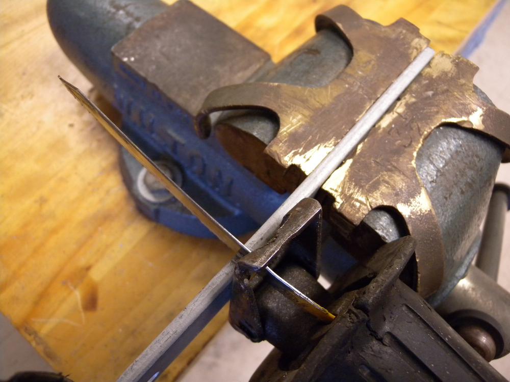
- Because vises are intended to compress and fix objects and materials in place, their use is relatively cut and dried (Figure 3-7). Open the jaws of the vise wide enough to accept the material and then compress until secure. Soft material can be easily damaged by the jaws of the vise if over compressed. To prevent this, cover the jaws with brass or wood.
Adhesives and Fasteners
The world is held together with adhesives and fasteners. Adhesives are compounds that produce both temporary and permanent bonds that secure, seal, and mask. Fasteners are mechanical devices that compress material together using a simple machine. Fasteners produce both temporary and permanent bonds by means of a mechanical advantage.
Adhesives
Adhesives are the chemical alternative to a fastener’s mechanical bond. There are many types of adhesives designed for specific applications ranging from simple wire isolation to bonds meant for extreme temperatures.
- Adhesive
- The adhesive refers to the actual material component that is responsible for bonding.
- Backing
- The backing is the film on which the adhesive is applied, allowing for two or more materials to be bound together. Most backings are made out of plastic or natural materials and serve to provide tension support to the adhesives bonding power.
Tapes
It is important to note the environmental conditions your tape will encounter in order to ensure its optimal performance. Use Table 3-1 to help you decide which type of tape will work best for your project.
| Type | Outdoor | Wet | Dry | Hot | Cold |
Cellophane | No | No | Yes | No | Yes |
Duct | Yes | Yes | Yes | Yes | Yes |
Electrical | Yes | Yes | Yes | No | Yes |
Masking | No | No | Yes | No | Yes |
Polyimide | Yes | Yes | Yes | Yes | Yes |
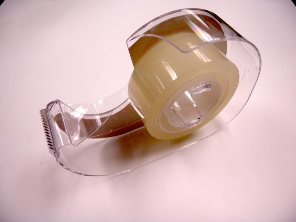
- Cellophane
- This general tape type is designed for use in light-duty situations (Figure 3-8). It consists of a thin plastic or cellophane backing that has been coated with single-use, pressure-sensitive adhesive. Because this tape type is not meant to be removed, the tape is easily torn and often leaves behind adhesive residue.
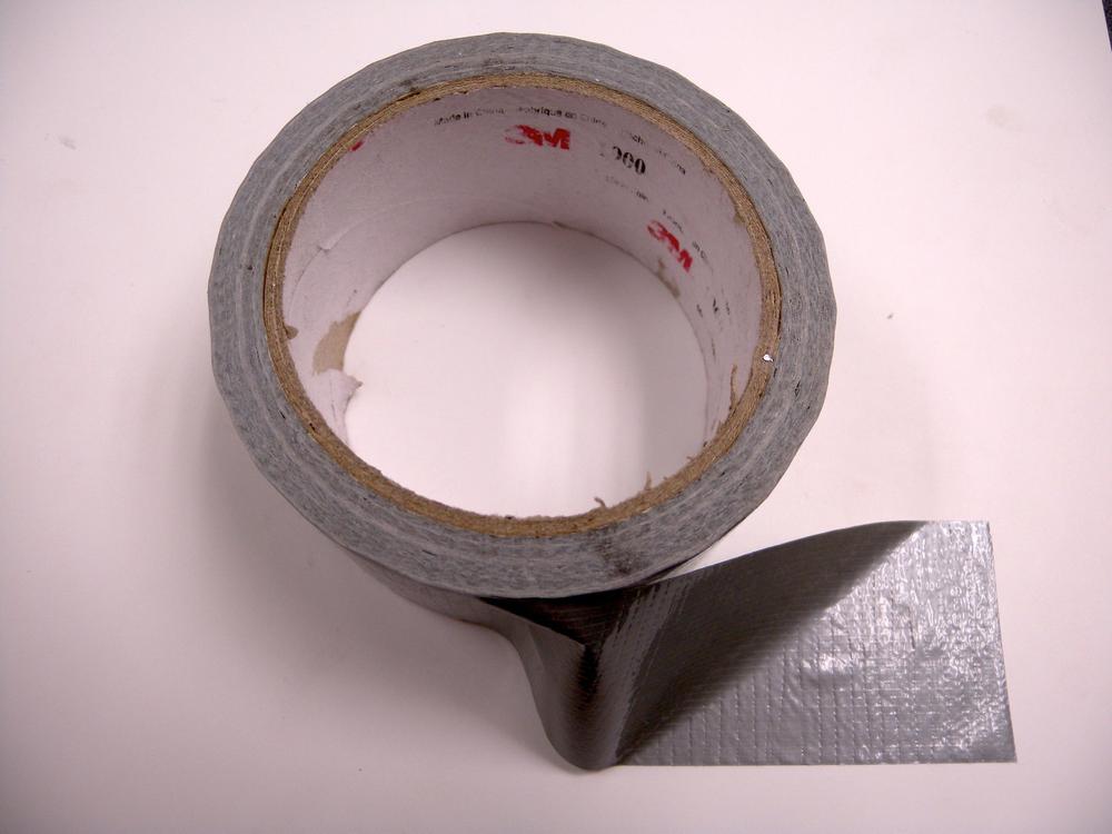
- Duct
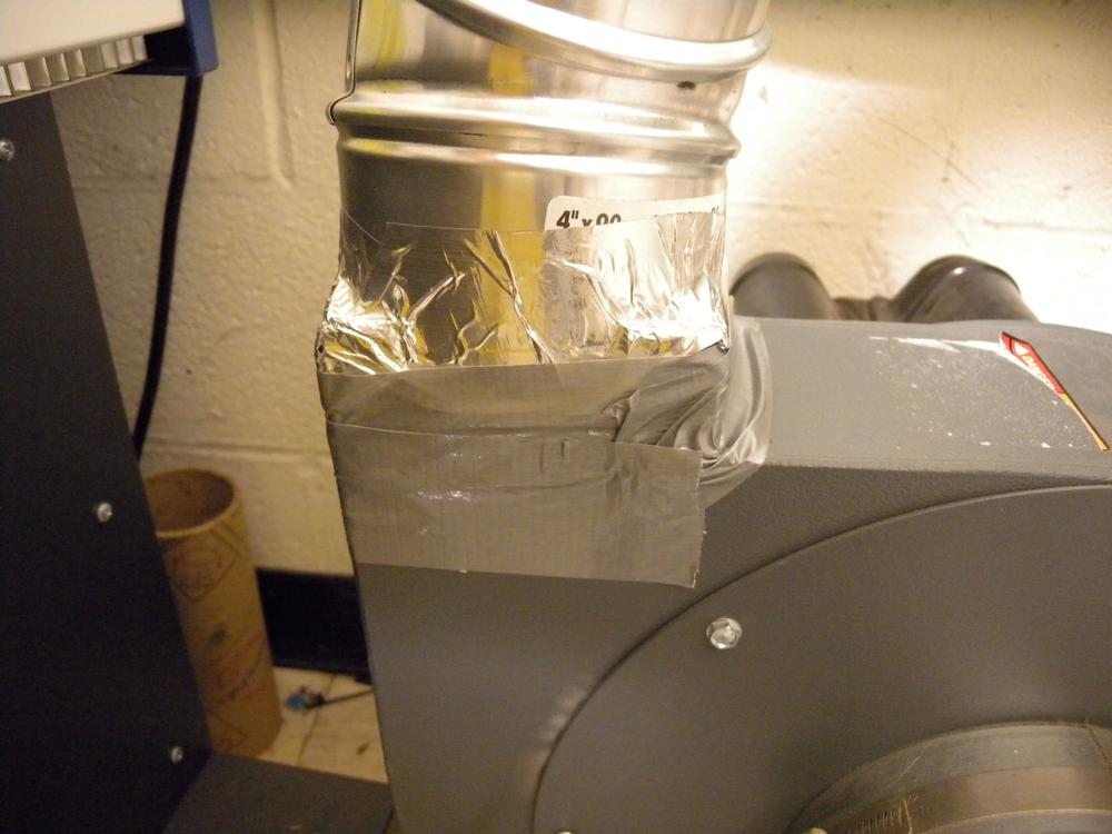
- Duct tape certainly has a reputation for being the “fix-all” adhesive for virtually any project (Figure 3-9). This tape comprises a fiber-reinforced polyethylene backing with a rubber-based adhesive and features excellent tack characteristics. New advances in duct tape technology have attempted to solve the material degradation problem experienced when duct tape is continuously exposed to the elements. This adhesive, once solely used for installing and mending ventilation systems, has become a humorously useful universal tool.
Steve Smith’s “The Red Green Show” is a wonderfully comedic do-it-yourself sitcom where a majority of the projects involve the use or misuse of duct tape.
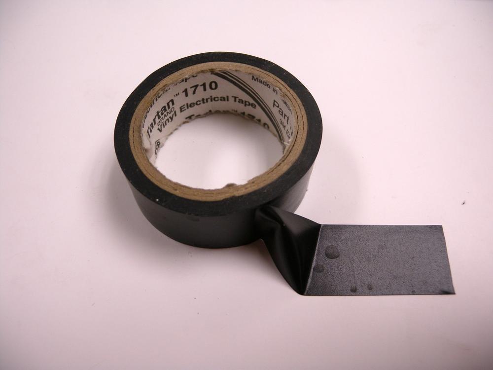
- Electrical
- Electrical tape is another type of pressure-sensitive adhesive that is electrically non-conductive, making it great for insulating exposed wires (Figure 3-10). This tape type consists of a PVC backing material coated with a waterproof rubber resin adhesive. Depending on the brand, electrical tape is designed to withstand environmental temperatures from –18°C to 105°C and will not degrade under exposure to ultraviolet (UV) light. All this being said, heat-shrink tubing should be used in lieu of electrical tape whenever possible because electrical tape tends to lose its holding power and become unstuck over time.
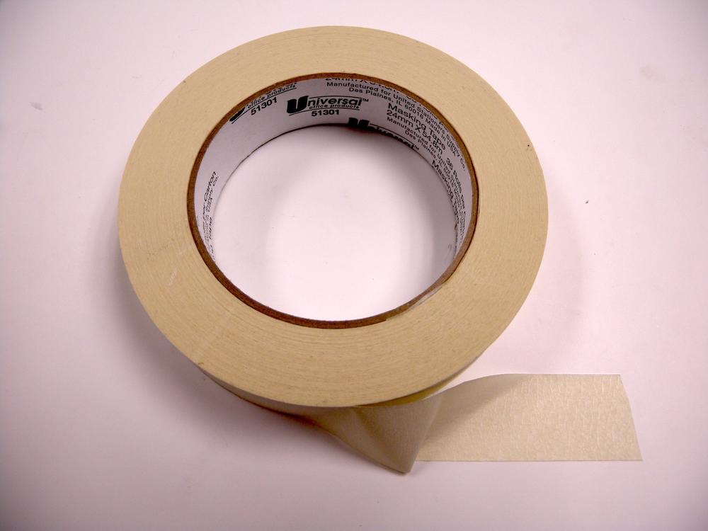
- Masking
- Masking tape is a great adhesive for projects that only require temporary joining (Figure 3-11). This tape is generally made from paper backing material that is coated with a gummy adhesive that conforms to surfaces and can be removed without leaving residue. These characteristics make masking tape an ideal adhesive for temporarily securing parts while gluing, masking off areas for painting, and labeling components. Blue painter’s masking tape actually functions as a good build surface for ABS 3D printing.
- Polyimide
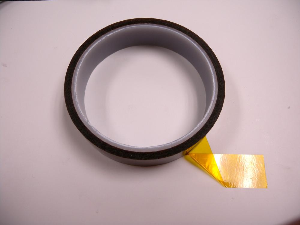
- Polyimide, or Kapton tape, has become increasingly popular in the Maker world due to its high temperature tolerance, electrical insulation, and excellent tack characteristics (Figure 3-12). This tape type consists of a polyimide material backing with a silicon adhesive. Polyimide tape also functions as an excellent build surface material for ABS and PLA 3D printing.
- General Tape Use
- The elements and working environment can stress tape resulting in it losing its grip. Also, tapes like duct and electrical deteriorate over time leaving a sticky residue behind (Figure 3-13). When using tape to secure your work, don’t touch the adhesive as the oils on your skin can lessen its grip. Lay the tape flat across the surface and gently rub the backing to promote adhesion.
Glues
It is important to note the environmental conditions your glue will encounter and the surfaces it will be used on in order to ensure its optimal performance. Use Table 3-2 to help you decide which type of glue will work best for your project.
| Type | Wet | Dry | Hot | Cold | Wood | Plastic | Metal | Strength |
Hot melt | Yes | Yes | No | Yes | Yes | Yes | Yes | Medium |
Super glue | Yes | Yes | Yes | Yes | Yes | Yes | Yes | High |
White | No | Yes | No | No | Yes | No | No | Low |
Wood glue | No | Yes | No | No | Yes | No | No | Medium |
- Hot Melt
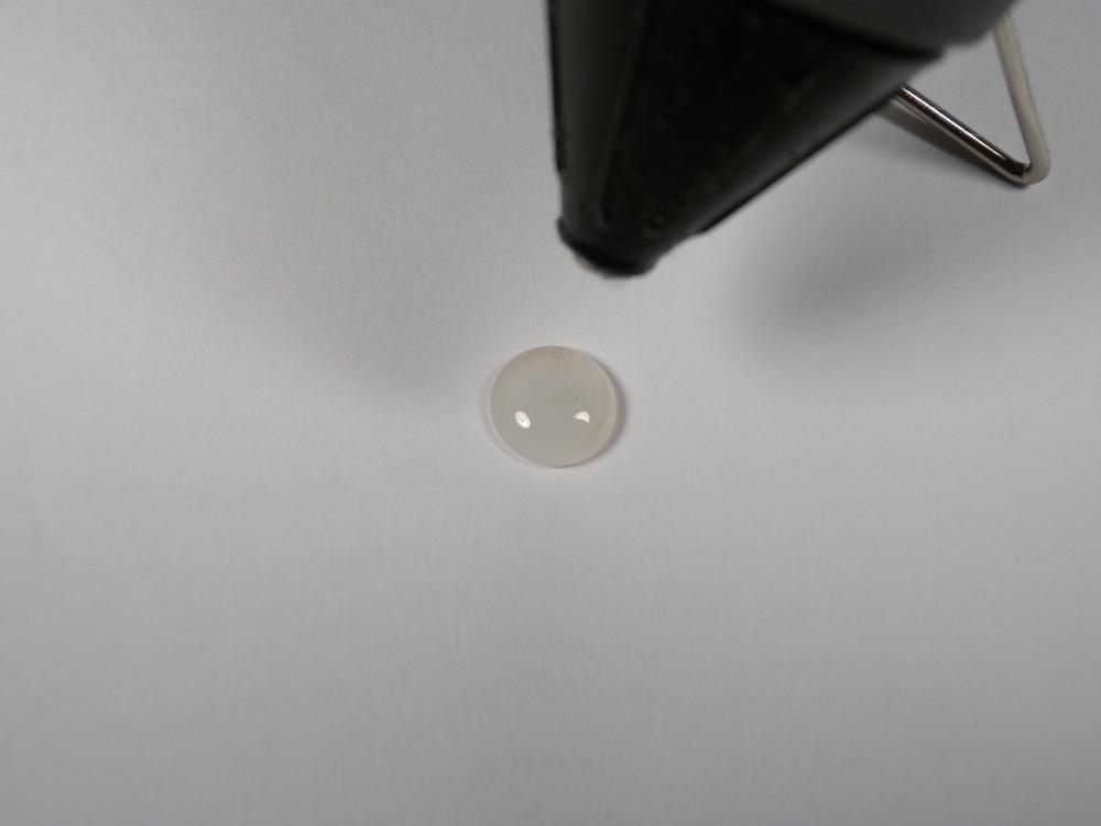
- Hot melt is a solvent-free thermoplastic adhesive that works in conjunction with a heating element to liquefy the feedstock for application (Figure 3-14). The adhesive then quickly sets after cooling, producing a strong bond on a variety of materials including wood, fabric, and plastic.
- Super
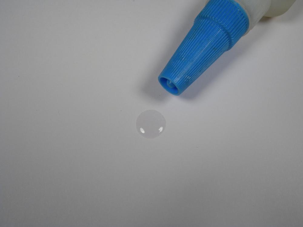
- The name says it all (Figure 3-15). Super glue, or cyanoacrolate, is a quick-drying general purpose adhesive that is good for bonding metals, rubber, plastic, ceramics, and wood. This adhesive type is designed to cure within 20 to 30 seconds, depending on viscosity, and can be dramatically decreased with the addition of a spray-on accelerator. The curing of super glue is an exothermic reaction, which means it produces heat when curing. Ensure that you are only gluing materials that can withstand the heat generated without deformation or consider using a slower-cure super glue if you are unsure. Super glue is prone to quickly polymerize on skin contact; however, you can easily remove it with acetone or nail polish remover.
Do not use super glue anywhere you require transparency, such as on the lenses of a pair of glasses. The volatiles in super glue have a tendency to creep across smooth surfaces and can cloud them with a semi-permanent white film. So do not use super glue to fix your glasses!
- White
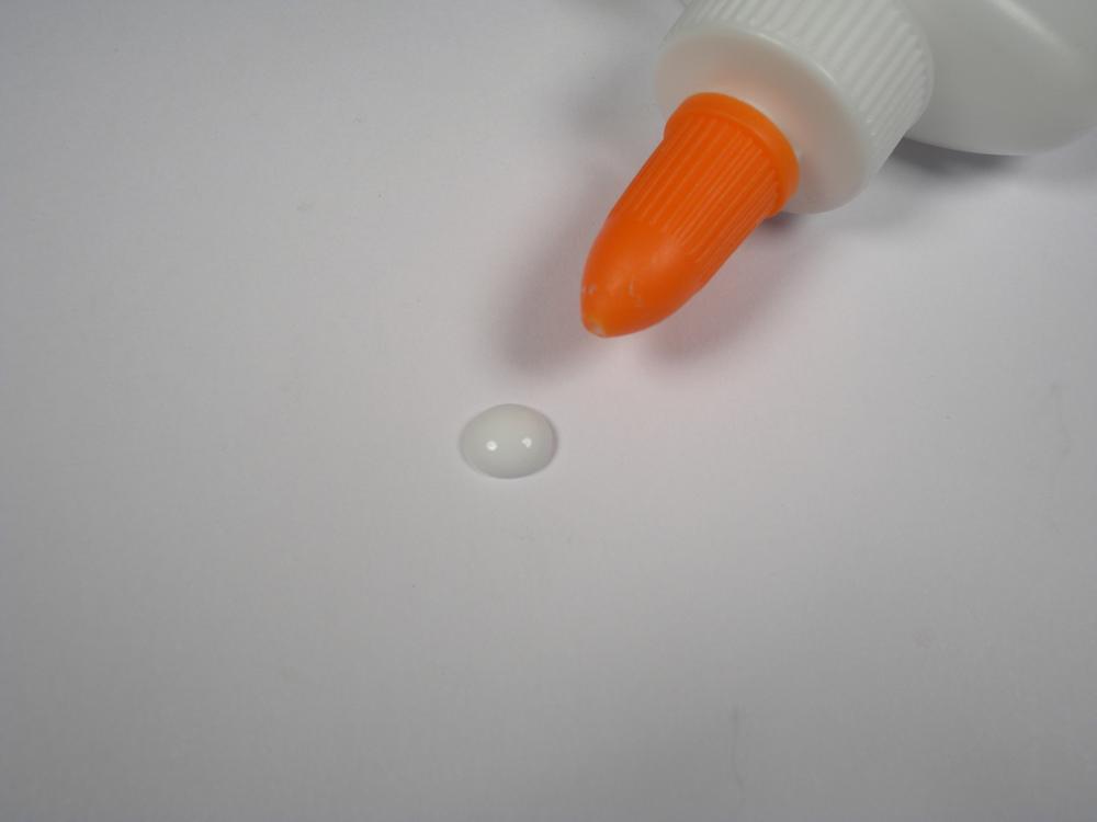
- White glue, or general purpose glue, is a staple product for any primary-school classroom (Figure 3-16). This inexpensive adhesive made from polyvinyl acetate is designed for use on porous materials that will not come in contact with water. Because this glue is slow-setting and exhibits relative low strength, it is only recommended in a pinch. After application, the project should be clamped for 30 minutes and allowed to cure for 24 hours.
- Wood
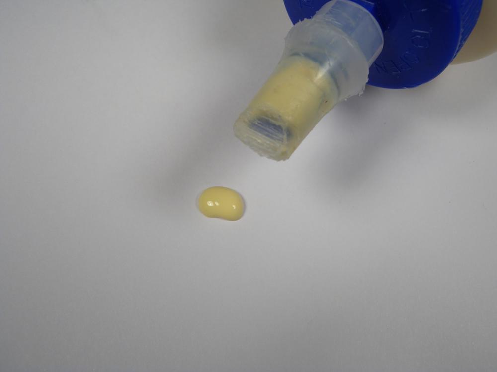
- Wood glue is an excellent alternative to white glue because it forms a stronger bond, dries quicker, and can be weatherproof (Figure 3-17). This glue type is made from an aliphatic resin with a slightly yellow appearance. After application, the project should be clamped for 30 minutes and allowed to cure for 24 hours.
- General Glue Use
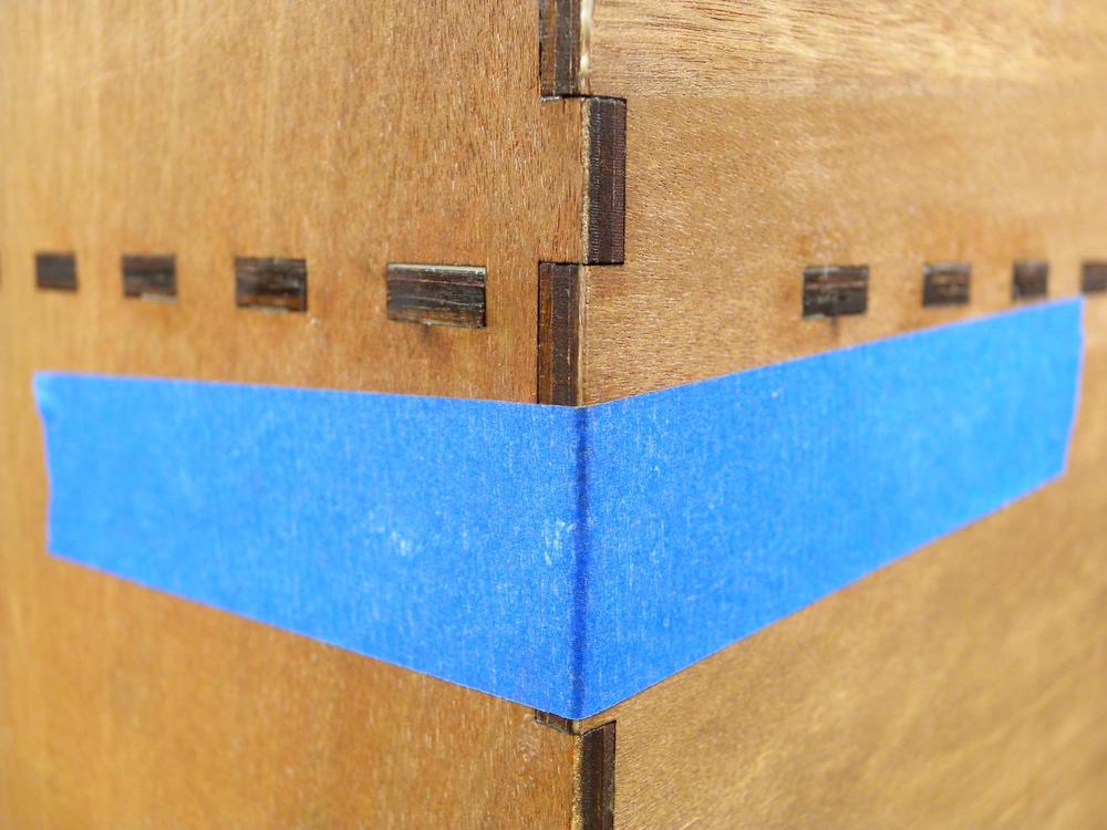
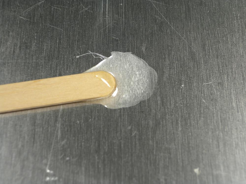
- Glue is designed for one purpose, to adhere two or more objects together by bonding to the material’s surface. This is accomplished by first preparing the surface to better adhere to the glue. For porous surfaces like wood, not much preparation is needed because the glue has a ready-made means for gripping the material. Other materials, like metal and plastic, require surface preparation prior to gluing. First remove any oil or residue from the surface of the material with alcohol and wipe clean. Lightly scour the surface with medium-grade sandpaper in a criss-cross pattern. The scratches made by the sandpaper will give the glue a better surface to which to adhere. Apply the glue to each component and press together. Glue works best if left undisturbed and in compression (Figure 3-18) for the entirety of the cure time. Disturbing or not pressing the joint together will result in a poor glue joint that will ultimately fail.
Specialty Glue
Use Table 3-3 to help you decide which type of specialty glue will work best for your project.
| Type | Wet | Dry | Hot | Cold | Wood | Plastic | Metal | Strength |
Epoxy | Yes | Yes | Yes | Yes | Yes | Yes | Yes | High |
Thread-lock | Yes | Yes | Yes | Yes | No | No | Yes | High |
- Epoxy
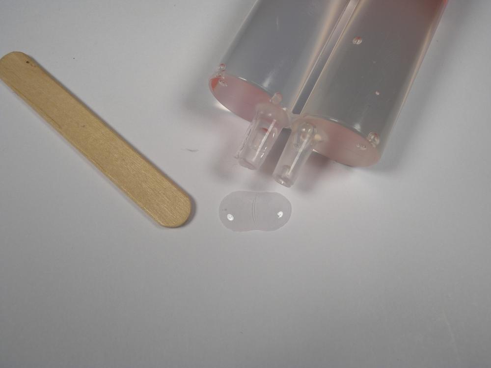
- Epoxy is a two-part adhesive comprising resin and hardener (Figure 3-19). You measure the two liquids to a predetermined ratio and throughly mix before applying. This initiates an exothermic reaction that takes anywhere between 5 and 30 minutes to fully cure, depending on type. You can use epoxy to adhere a variety of materials, including wood, plastic, metal, and glass. Certain formulas of epoxy, like JB Weld, can withstand high temperatures and can even be used to repair engine components!
- Epoxy Use
- Most epoxies follow a 50/50 resin-to-hardener ratio. To mix epoxy, begin by putting on a pair of gloves and measuring equal amounts of hardener and resin into two separate cups. If needed, you can make these measurements using a scale. Pour the hardener into the resin cup and mix for 1 minute. Ensure that both compounds are completely mixed (Figure 3-20) before using; poorly mixed epoxy will not properly set. Apply the mixed epoxy to your project, but don’t throw away the mixing cup. You can use this cup as a representative sample to determine the state of the solidifying epoxy without disturbing the project.
Epoxy produces an exothermic reaction when mixed, which can melt thin plastic cups.
- Thread-Lock
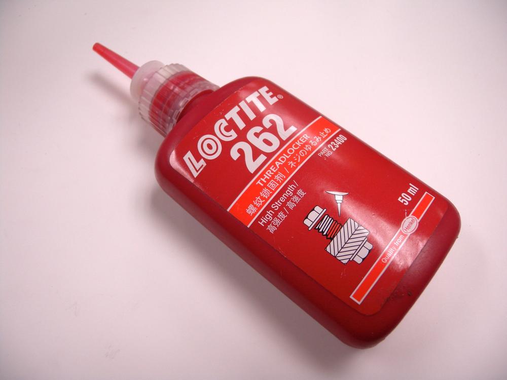
- Thread-locking adhesive is a vital component for securing nuts and bolts when used in situations that experience any amount of vibration or impact that might loosen the fastener (Figure 3-21). Thread-locking adhesive is an anaerobic compound that prevents this loosening by filling the small gaps found between a fastener’s interlocking threads. The adhesive then bonds to the mating interface and produces either a permanent or semi-permanent bond. Thread-locking adhesive is typically color coded to indicate the strength of the bond, as listed in Table 3-4.
| Color | Locking Shear | Notes |
Green | 1500 PSI | Low viscosity allows for application without removing fastener |
Blue | 1200 to 1500 PSI | Low shear permits fastener removal |
Red | 2500 to 3500 PSI | Only removable by heating fastener to 260° C |
- Thread-Lock Use
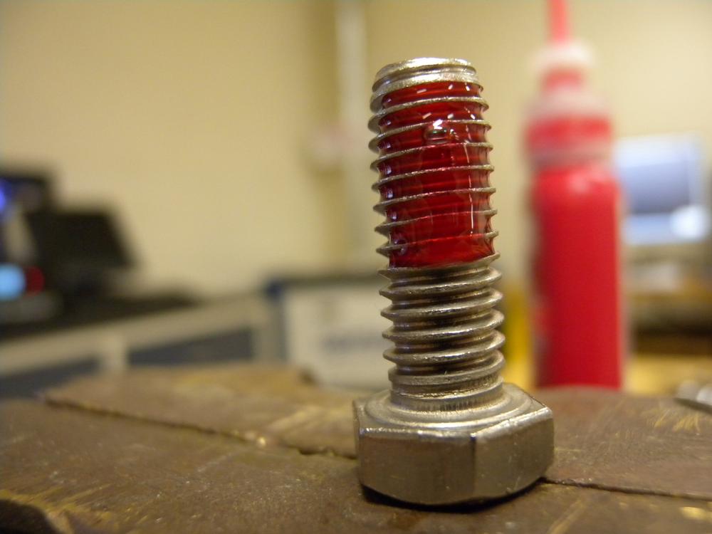
- Before using a thread-locking adhesive, you must clean the threads of the fastener to remove any compounds that might prevent adhesion (Figure 3-22). Place a small drop of thread-lock onto the threads of the fastener and secure in place with a washer and a nut. The adhesive will bond within the manufacturer’s stated time and can only be removed by following the color-coded procedure.
Fasteners
Fasteners provide a mechanical coupling between two or more objects and feature a wide range of sizes and designs. The earliest fasteners were forged by hand and revolutionized construction projects, making bigger and stronger structures possible. Today, Makerspaces rely on a wide range of threaded fasteners in virtually every project.
The best rule of thumb for determining how to loosen or tighten a fastener is the age-old saying “righty-tighty lefty-loosey.” This saying illustrates the angle of the fastener’s threads allowing for the fastener to tighten when turned clockwise and loosen when turned counterclockwise.
The common fastener features are identified as follows:
- Head Style
- The threaded fastener’s head style dictates both the type of tool used to drive the fastener as well as how it is secured. Each head style is designed to optimize the fastener’s capability.
- Thread Size
- The thread size specifies both the diameter of the fastener and the quantity of threads per inch or millimeter. Standard-sized fasteners are identified using a number scale for sizes under 1/4 in and fractional for sizes above that. Metric fasteners are identified with a similar number scale, although the metric unit is proceeded by an uppercase M. Both standard and metric fasteners also include a thread-per-unit identifier that proceeds the diameter. A 4-40 standard screw will measure 0.112 inch in diameter and has 40 threads per inch.
- Diameter
- The most important feature of any fastener is its diameter, which dictates both the size of the hole it can fit as well as the type of threads it can support. Each fastener is designed to mate with either a hole or fastener that corresponds to its diameter. If a fastener is used whose diameter is too small for the hole or fastener, the fastener will loosen over time, produce a poor coupling, or fail entirely.
Rivets and Grommets
- Blind Rivet
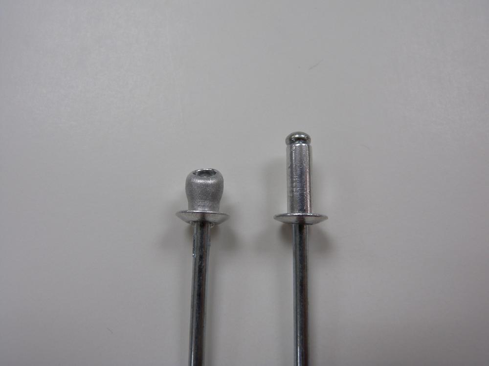
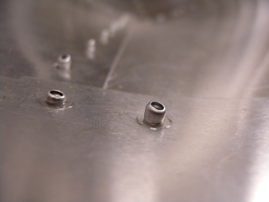
A blind rivet, or pop rivet, is a nonthreaded mechanical fastener that produces a permanent coupling between thin metal, wood, and plastic (Figure 3-23). When these fasteners are secured, their body is physically deformed as a nail-shaped mandrel is pulled into its body, producing a quick and strong joint. When the rivet is fully compressed (Figure 3-24), the mandrel shears off, leaving only the rivet behind.
Blind rivets can fasten a variety of materials depending on their composition. Table 3-5 illustrates different rivet material types, their diameter, and the type of material they can secure.
- Rivet Gun
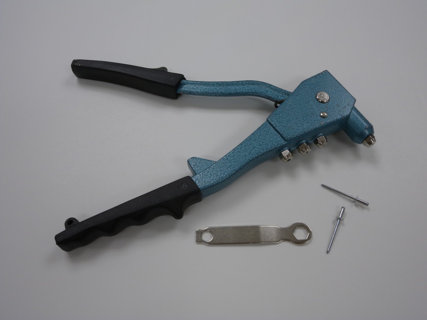
- Rivet guns are used to secure blind rivets in place by grabbing and pulling the mandrel through the rivet after it has been seated (Figure 3-25). These tools are accompanied by a series of nosepieces that correspond to the rivet’s mandrel diameter.
- Rivet Gun Use
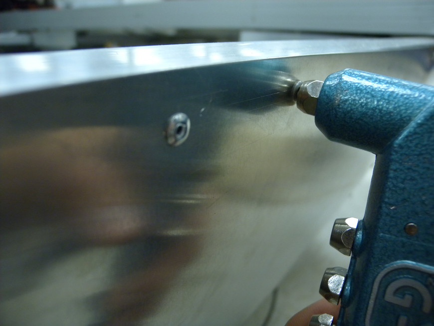
Begin by drilling an appropriately sized hole for the rivet in your material. If you are overlapping two or more pieces of material, clamp them together and drill them all at once. Attach the proper nosepiece to the gun and slide in a rivet. Push the rivet into the hole and squeeze the gun’s handle (Figure 3-26). The mandrel should pull through the rivet and pop off. If it doesn’t, simply squeeze the handle again until it does.
To remove a secured rivet, simply use a drill and bit that is slightly larger than the rivet’s head and drill until the head pops off. Then, use a center punch to remove the remaining material. Be careful not to drill into your work!
Screws
- Hex-Head Cap
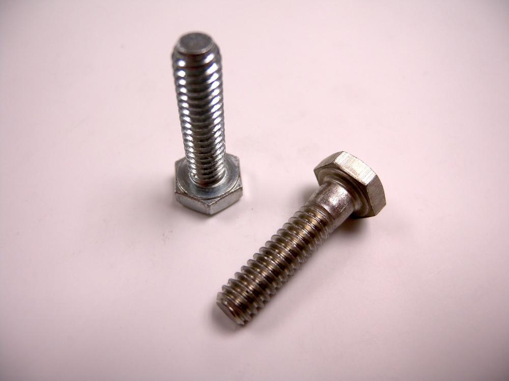
- Cap screws feature a hex-shaped head and are most commonly found in larger sizes (Figure 3-27). The robustness of the head and drive type makes it possible for cap screws to withstand a large amount of torque and resist wear.
- Machine
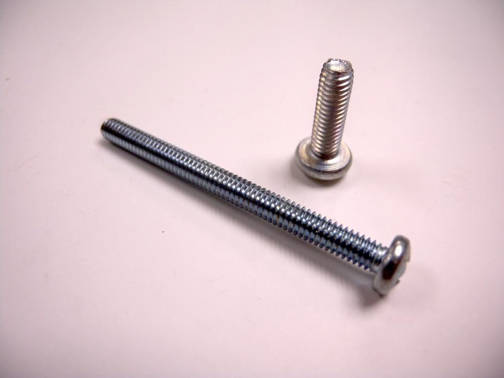
- Machine screws feature one of many drive system types and are commonly found in smaller sizes (Figure 3-28). The recessed drive, rounded head, and high quantity of threads per unit make machine screws ideal for most projects.
- Set
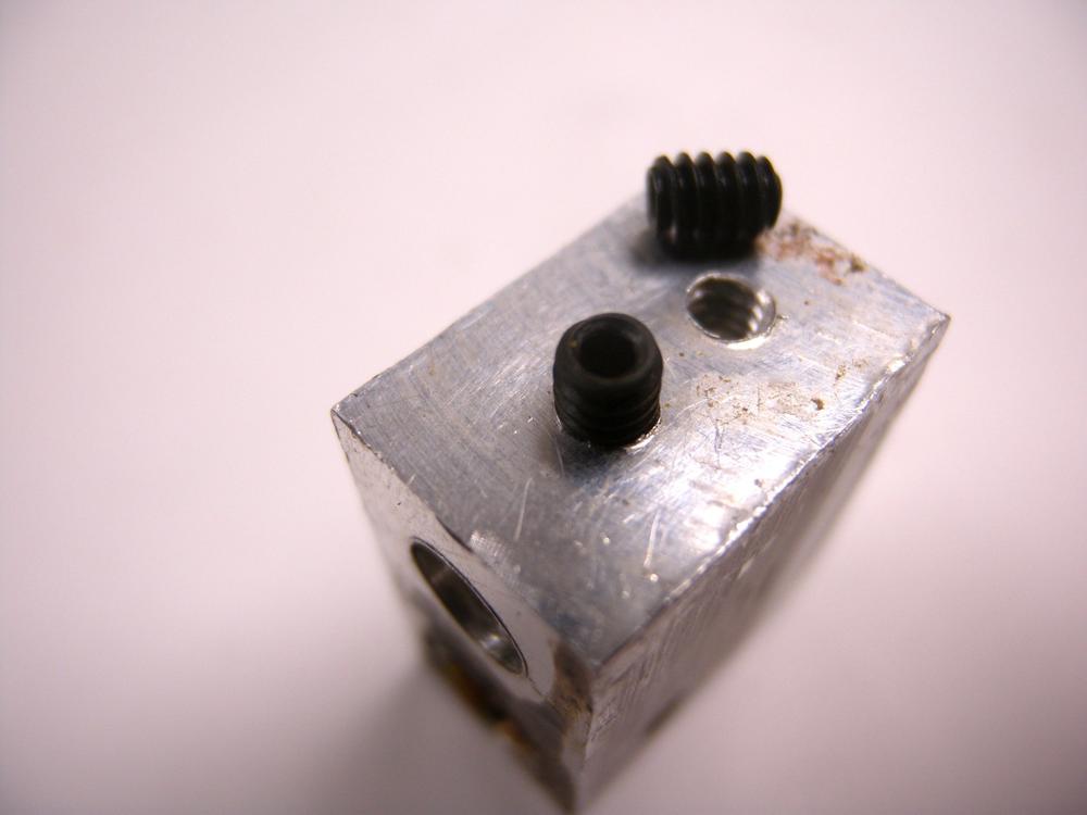
- Set screws are designed specifically for use in recessed areas (Figure 3-29). Because these screws do not have a head, they are only limited by the depth of the threaded hole. Most set screws are used to secure gears and pulleys onto shafts by driving into the shaft, securing the component in place.
- Sheet Metal
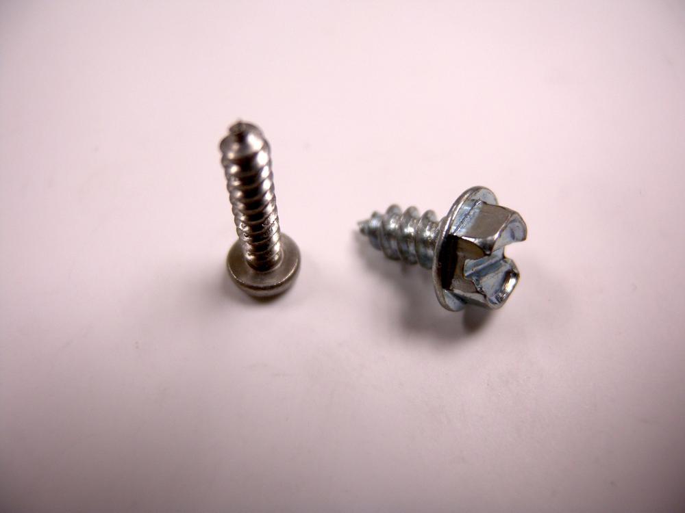
- Sheet metal screws feature an aggressive thread pattern that is designed to deform and bind to thin metal (Figure 3-30). These screws also work well with many types of wood and plastic.
- Socket-Head Cap
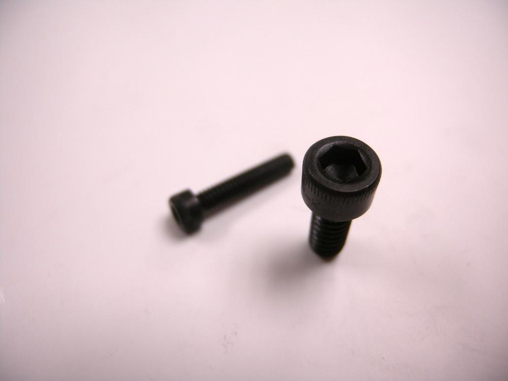
- Socket head cap screws feature a hexagonal drive enclosed in a round head (Figure 3-31). This design makes it possible for the screw to be entirely countersunk into the workpiece, providing for a more finished appearance.
- General Screw Use
- Screws are used in two configurations: threaded into a hole and secured with a nut (Figure 3-32). To thread a screw into a hole, align the proper-sized screw at the opening so that it is parallel to the hole’s wall. Counter-rotate the screw while applying a small amount of pressure until you feel a small click. This indicates that the threads of the screw have aligned with the hole’s threads and you can begin tightening down the screw. Trying to drive a screw without first aligning the threads can result in cross-threading which occurs when the threads cross over each other, causing permanent damage. To secure a screw with a nut, slide the screw through the workpiece and place a washer over the exposed threads at the end of the screw. Attach a nut over the end and tighten until secure.
Nuts
- Acorn
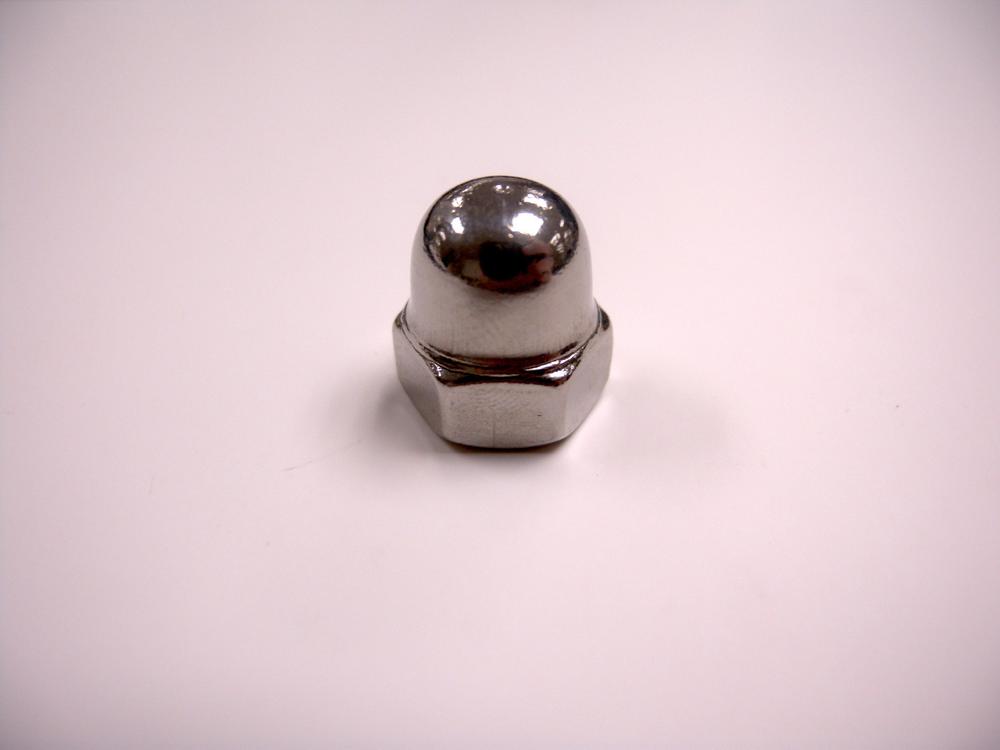
- Acorn nuts feature a hex shaped drive and a domed covering over one side (Figure 3-33). This dome is designed to prevent accidental contact with the exposed threads; their primary purpose is safety, but they are also a decorative feature.
- Captive
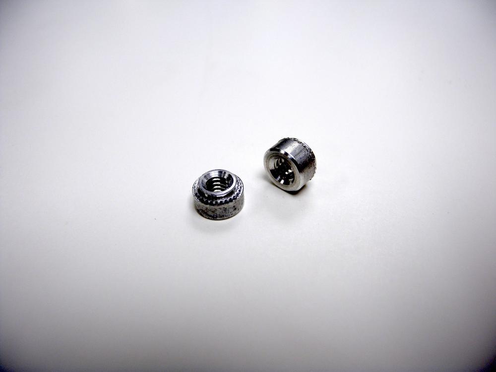
- Captive nuts are designed to be embedded into material and function as an alternative to a threaded hole (Figure 3-34). These nuts feature a press-in mounting system that allows for the nut to mechanically interface with the desired material when compressed.
- Hex
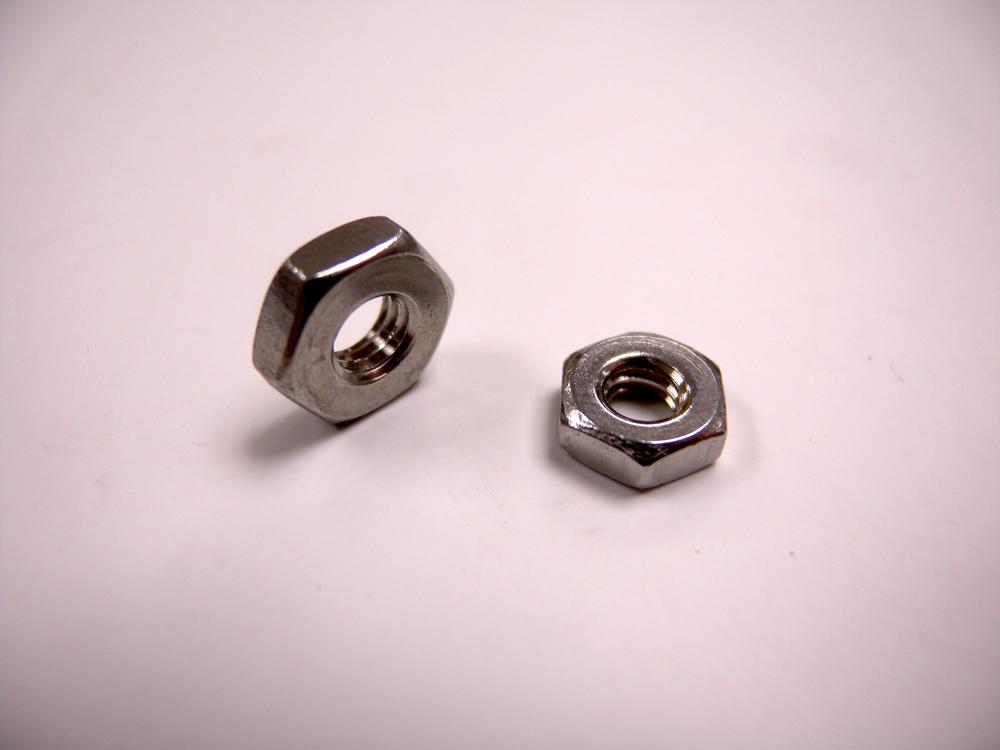
- Hex nuts are the most commonly used nut and feature the same hex shape as cap screws (Figure 3-35). For situations in which the nut is prone to loosening, a second nut can be added to the fastener to “jam” the first in place, preventing movement.
- Lock Nut
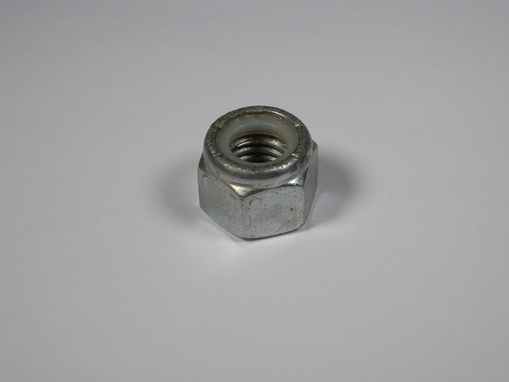
- Lock nuts are identical to hex nuts in shape, but include an embedded nylon locking ring at the top of the nut (Figure 3-36). When the nut is fully threaded onto a fastener, the nylon insert binds with the fasteners threads, preventing the nut from loosening.
- Wing
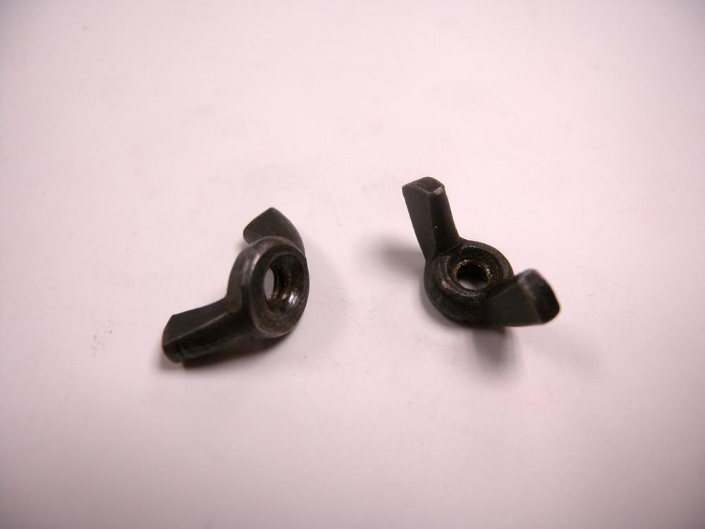
- Wing nuts feature two wing-shaped extensions with which you can twist the fastener on and off with just your fingers (Figure 3-37). Because wing nuts lack the standard hex shape, they are only intended for use on interfaces that do not require a large amount of compression.
Washers
- Flat
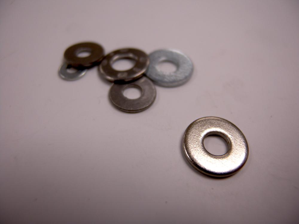
- Flat washers are simply stamped pieces of sheet metal that act as a barrier between the nut and the fastened material (Figure 3-38). Without a washer, nuts will deform the workpiece, making them more prone to loosening over time.
- Lock
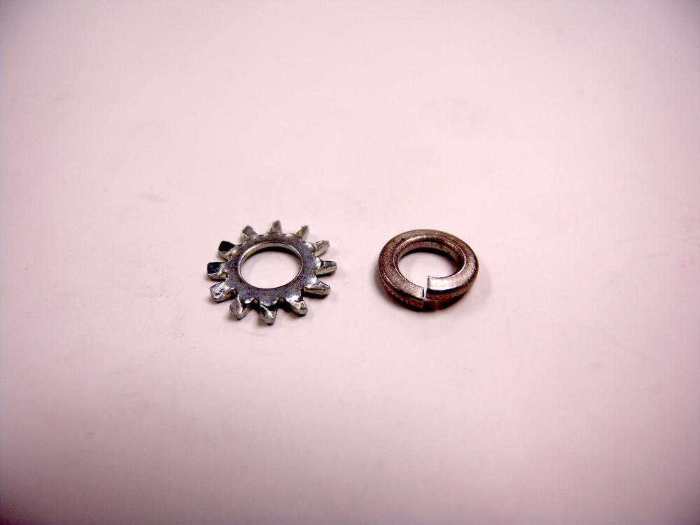
- Lock washers are used for situations in which the fastener is prone to loosening (Figure 3-39). There are many types of lock washers, including split ring, internal tooth, and external tooth, and all are designed to embed themselves in both the fastened material and the nut.
Measurement
Measurement devices are designed to verify the dimensions of an object or to establish the dimensions of something that is to be created. By properly using dimensional measurement tools, you can verify and adjust your Makerspace projects.
Dimensional
You use dimensional measurement tools to perform quick and relatively accurate measurements. You can use these tools for both angle and length; thus they serve as the backbone of most design.
The common dimensional tool features are identified as follows:
- Graduations
- Dimensional measurement tools are divided into a series of graduations relative to that tool’s measurement system. Standard, or English, measurement tools are typically delimited in inches, which are then subdivided to 1/16 in. Metric measurement tools are typically divided into centimeters, which are then subdivided down to the millimeter. Although there are dimensional measurement tools that can measure to higher resolutions, they are typically done with tools design specifically for high-precision measurement.
Angular
- Level
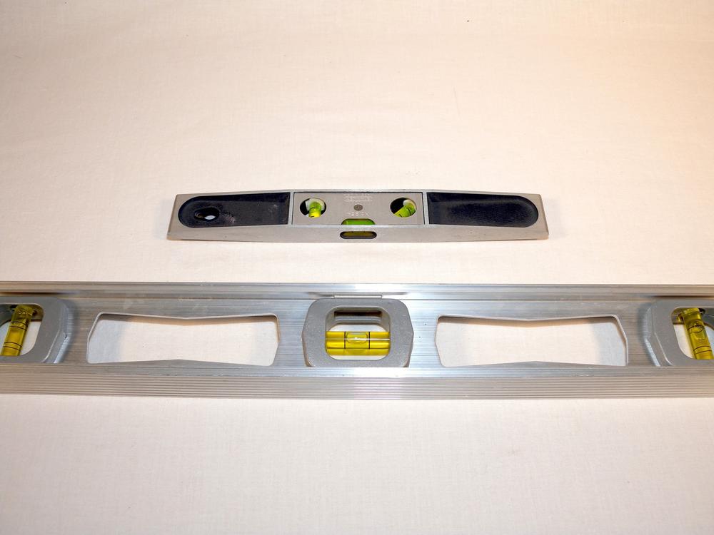
- A level relies on the Earth’s constant gravitational pull as its measurement reference (Figure 3-40). Each level consists of a straightedge (an unmarked rule) and one or more transparent vials containing a mysterious fluorescent-yellow fluid and a bubble. The vials are marked with two lines indicating the center of the vial as well as the width of the bubble. When the bubble is positioned in the center of the vial, the level is, well…level.
- Level Use
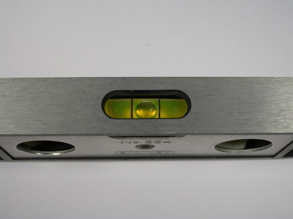
- Levels are used by placing the tool onto the surface that is to be measured (Figure 3-41). Ensure that the level does not wobble and is securely positioned. Each level contains one or more bubble vials that are used to determine how level an object is. Looking at the vial, adjust the object until the bubble is centered between the two lines.
- Protractor
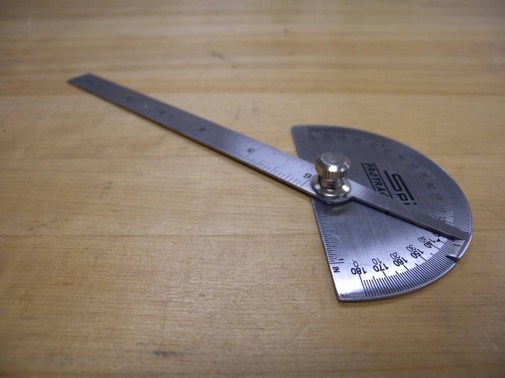
- Protractors offer a means for measuring angles (Figure 3-42). This device contains a series of angle graduations, typically illustrating angle to the degree. Some protractors also have an attached rule that is used as a pointer to indicate angle while offering another measurement surface.
- Protractor Use
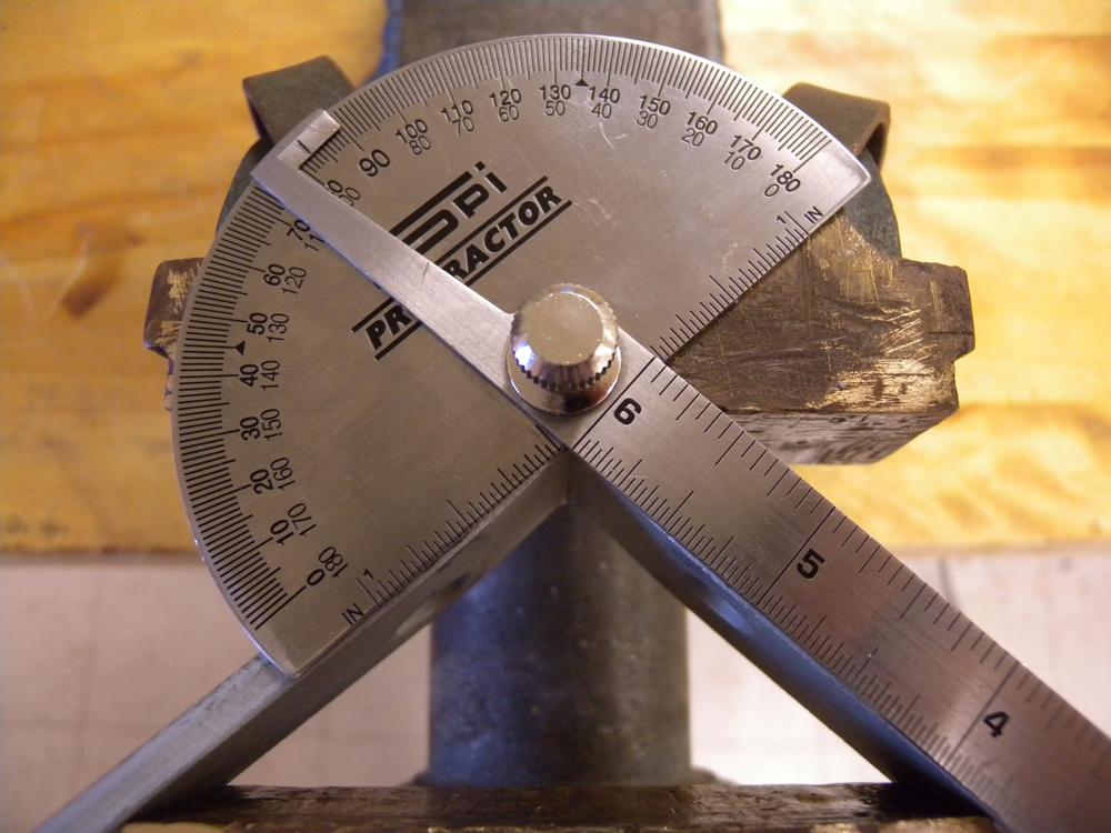
- To use a protractor, align the base of the protractor to the reference side and position the arm to the desired angle (Figure 3-43). This tool can be used to both measure the angle of an existing feature or provide a reference angle for marking a new feature.
Linear
- Rule
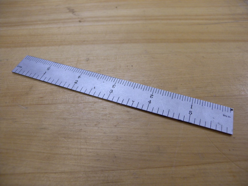
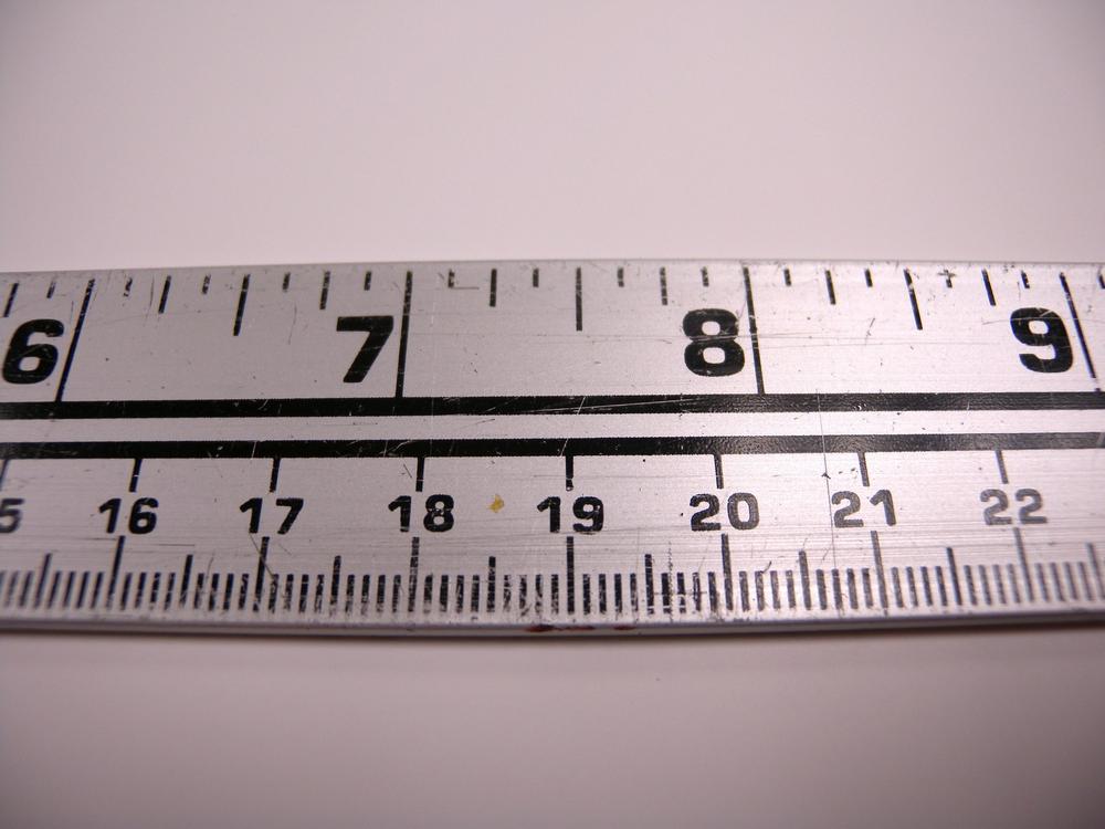
- Rules are bars of wood, plastic, or metal marked with graduations in the unit of measure for the device (Figure 3-44). There are many types of rules that are designed to assist as much as possible in the measurement and identification of a material’s width, length, and height. Precision or machinist’s rules offer higher-resolution graduations and deliver much higher measurement precision.
- Square
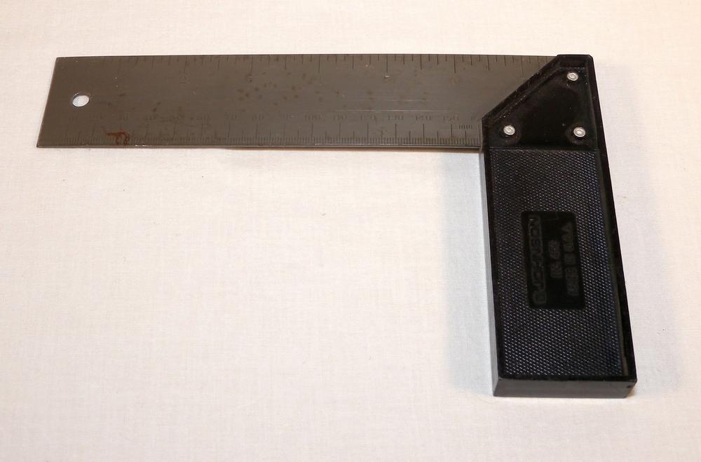
- Squares, or framing squares, provide an accurate 90-degree measurement reference (Figure 3-45). Each side of the framing square displays graduations that extend from the root of the angle to each end. This tool can be used to provide perpendicular measurements and markings relative to a side as well as to verify that an angle is square.
- Tape Rule
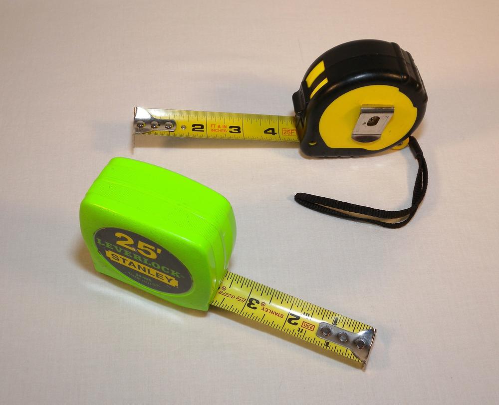
- Tape rules offer the same measurement method as a standard straight rule, but allow for much larger measurements (Figure 3-46). This device uses a polyester-coated spring steel blade that uncoils as the tape is extended. When the measurement is complete, a release is pressed and the tape rewinds back into its enclosure. Although tape measures are good at making large measurements, there is a lot of room for error in the measurement due to deflection of the tape and off-angle positioning. If a higher-precision measurement is required, a long solid rule is recommended.
- T-Square
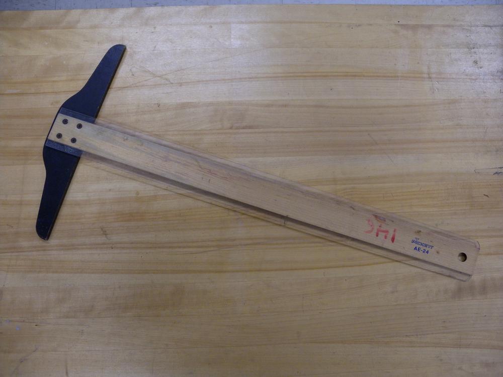
- T-Squares offer a head that is perpendicular (90 degrees) to the leg—the part of the t-square with marked graduations (Figure 3-47). This head serves as a reference for measuring and marking with higher precision. Although most heads do not contain graduations, variations like the framing square offer graduations on both legs.
- General Linear Measurement
- Each linear measurement tool features a series of graduations that indicate the distance between two points (Figure 3-48). Metric rules are typically graduated down to the single millimeter, while standard or English rules measure down to 1/16th of an inch. Some rules, like machinist rules, can measure distances as small as 1/2 mm or 1/64 in.
Precision Linear
- Caliper
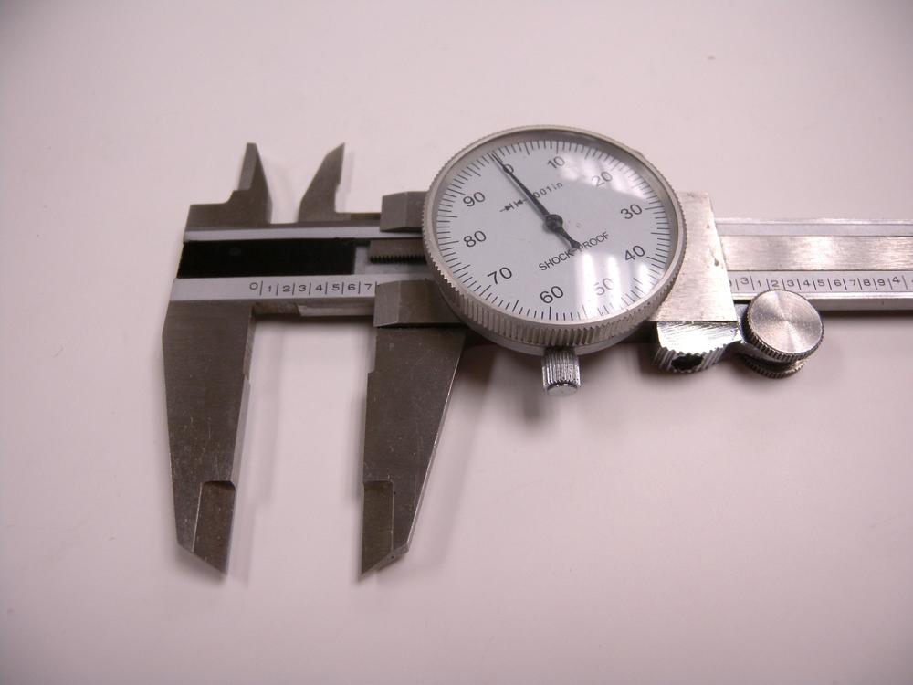
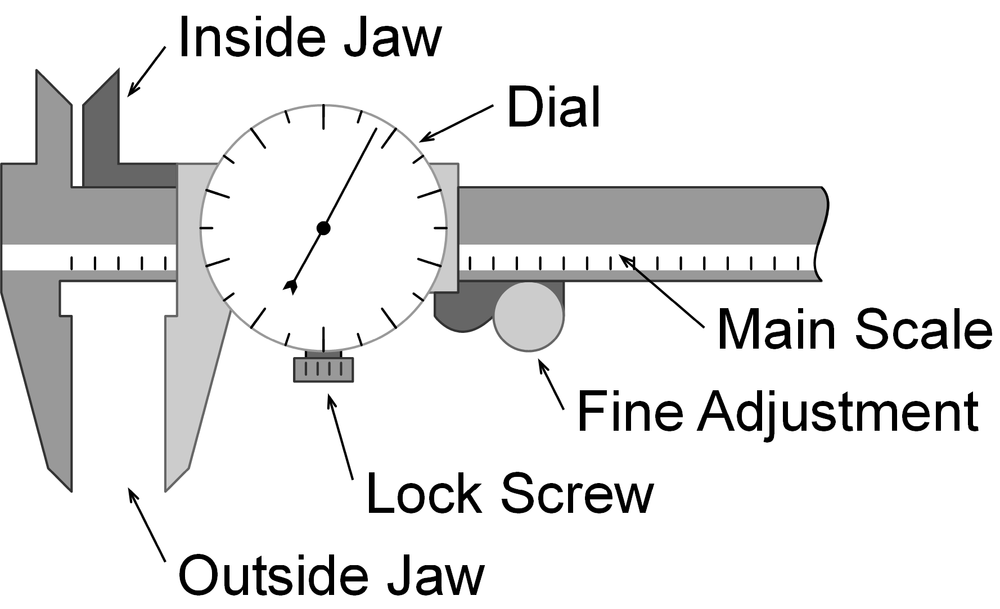
- A caliper can accurately measure the internal or outer diameter, thickness, or depth of an object (Figure 3-49). The caliper consists of six primary parts (Figure 3-50): the inside jaw, the outside jaw, the dial and lock screw, the fine adjustment, and the main slide.
- Caliper Measurement
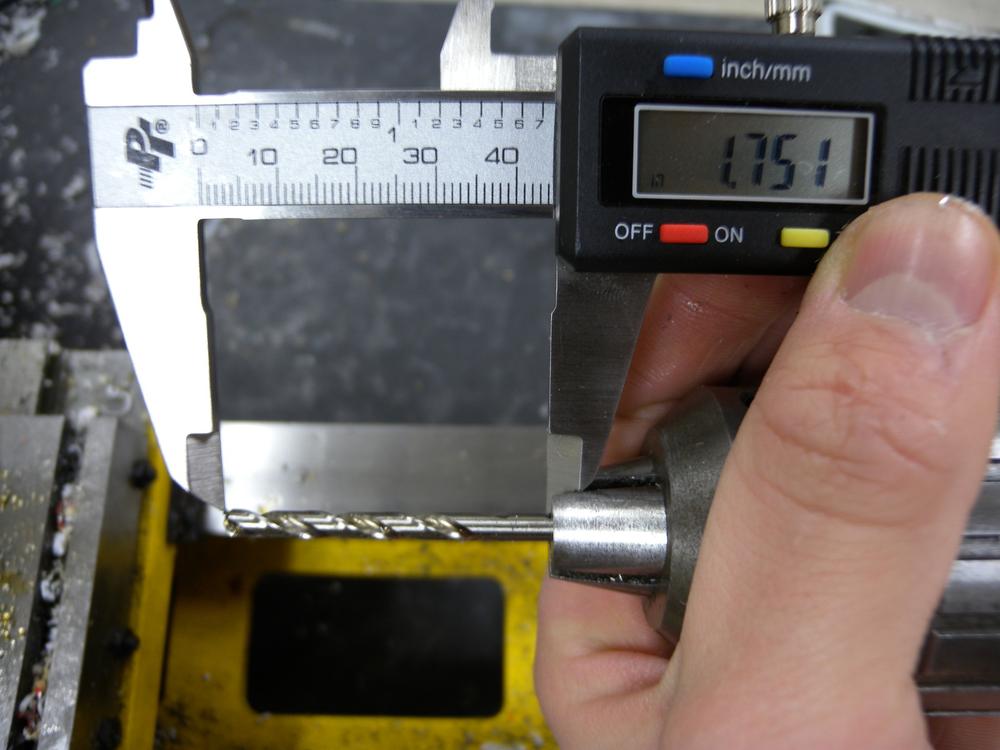
To make a measurement with a caliper, place the desired material between one of the measurement contacts, then use the fine-adjust roll to gently snug the contacts against the object. Next, read the last visible number on the main scale. Each large number on the bar represents 1 in and each small number represents 0.1 in. Read the indicator on the dial. Each dash represents 0.001 in. Combine the two numbers to get the measurement.
To calibrate the caliper, carefully slide the contacts together so that there is no gap (Figure 3-51). Next, carefully rotate the outside of the dial indicator until the “0” mark lines up with the indicator.
- Micrometer
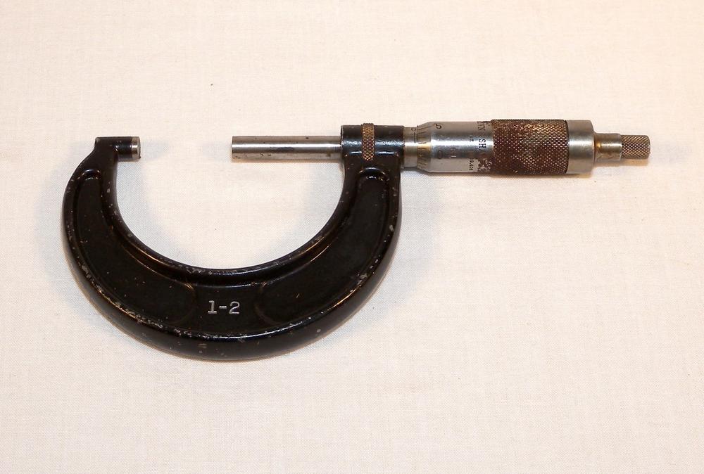
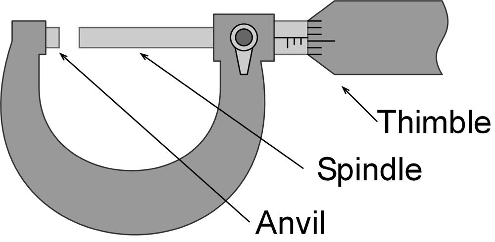
- A micrometer can accurately measure the thickness or width of an object with resolutions up to 1/10,000th of an inch or 1/100th of a millimeter (Figure 3-52). Micrometers contain a series of components that work together to produce very accurate measurement. The micrometer consists of three primary components: the anvil, spindle, and thimble (Figure 3-53).
- Micrometer Use
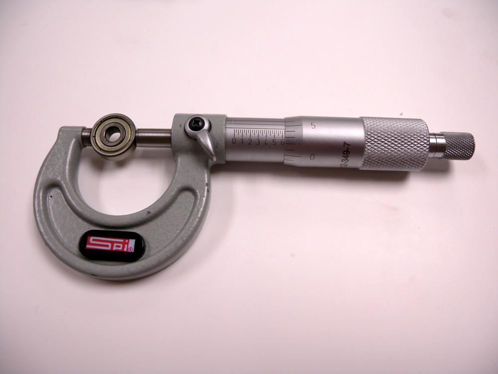
- To take a measurement with a micrometer, place the desired material between the anvil and spindle and then carefully rotate the ratchet on the back of the thimble until the ratchet slips (Figure 3-54). Next, read the highest visible number on the sleeve. This number acts as the tenths decimal in your reading. Then, count the number of lines on the sleeve past the highest visible number. Each line past the highest number counts as 0.025 in. Finally, read the number on the thimble that lies closest to the center line on the sleeve. Each mark indicates 0.001 in. Determine the measurement by combining all three numbers.
Inspection
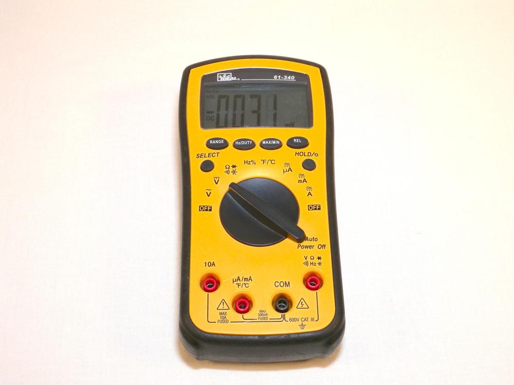
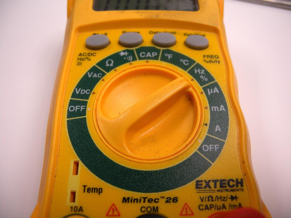
Inspection tools are used to investigate the operation of an object without interfering with its functionality. Both multimeters (Figure 3-55) and temperature measurement devices are integral to the Makerspace. Multimeters provide several methods for making electrical measurements. Although there are almost unlimited brands and types, they all include a standard set of tools. Most temperature measurements are made by using devices such as thermocouples, resistance temperature detectors (RTDs), thermistors, and solid-state sensors. Each of these devices have unique characteristics that can affect their accuracy, range, and use.
Multimeter
- AC/DC Voltage
- Multimeters can measure a wide range of both AC and DC voltages. The range is selected using the dial or is done automatically. Ensure that the voltage you are measuring does not exceed the limits of your device. If you do, there is a fuse that will blow when the limits are exceeded. Typically, you can replace fuses easily by removing the back of the meter and dropping in a new one. Remember, voltage is measured in parallel with the supply.
- Capacitance
- The capacitance function provides value measurement and verification. You can also use this function to identify the polarity of unmarked polar capacitors. Some multimeters have separate sockets designed for capacitor measurement; others use the test leads.
- Continuity
- You use the continuity function to determine whether a circuit is open or closed. This tool can be quite useful for isolating a circuit fault or for reverse engineering. The continuity test also shows the resistance between the two leads and can help determine line losses and short circuits.
- Current
- Multimeters typically have two levels of current sensing 0–400 mA and 401 mA to 10 A. This is done by measuring the voltage drop over a shunt resistor that’s a part of your multimeter. Using the 401 mA to 10 A function requires a reconfiguration of the test leads so that the red lead is positioned in the 10 A socket and the black lead is positioned in the ground socket. It is common to burn out the fuse on the current circuit when the test leads are incorrectly configured. This fuse can be replaced in the same manner as the multifunction fuse mentioned in the voltage sensing section. Remember, current is measured in series with the supply.
- Diode
- You can measure the polarity and voltage drop of a diode with this function. Connect the test leads to the diode’s anode and cathode and the display will indicate the voltage drop. You can also use this to determine the functionality of the diode as well as its polarity.
- Resistance
- Resistance measurement extends beyond the standard measurement of resistor values. You can also use it for circuit analysis and to help in determining faults. This function operates by passing a small voltage between the two leads and measuring the drop. By using V = IR, you can deduce the resistance.
- Frequency
- Frequency measurement is a great tool to have because you can use it to determine the function of oscillators, signals, and other low-frequency sources. Depending on your multimeter, frequency analysis usually ranges from 0–10 MHz.
- Inductance
- Multimeters measure inductance by connecting a precision resistor in series with the inductor and measuring the junction voltage when a signal is passed through the circuit. The multimeter can then derive the inductance based on the response to the signal.
- Temperature
- Some multimeters ship with thermocouples and can measure a wide range of temperatures. Because the thermocouple is a polar device, make sure that the sensor is connected correctly.
- Transistor
- Multimeters can measure transistor hFE or forward current gain of NPN and PNP transistors (not MOSFETs). Depending on the multimeter, there might be a series of holes configured in a row and in a circle pattern that accommodates connecting to the transistor’s base, collector, and emitter pins. Alternatively, the function of a transistor can be determined by using the multimeter’s diode test function and connecting the test leads to the base/emitter and base/collector respectively.
- General Multimeter Use
- To use a multimeter, you first select the desired measurement tool by rotating the selection dial to the desired function and inserting the test leads into the appropriate sockets. These sockets are marked according to their function and typically consist of a high current, ground, and multifunction position. Depending on the design of your multimeter, many of the functions have range limits. Ensure that you adjust the dial (Figure 3-56) to the approximate range of your source. If your measurement exceeds the limits of that function, you will get the infamous “OL” message, indicating the inability to make an accurate measurement.
Temperature
- Infrared
- Infrared thermometers utilize a small infrared sensor that measures the surface temperature of an object without making contact. These devices are quite useful at measuring temperatures that exceed the limits of thermistors or are sensitive to physical contact. Because these sensors are susceptible to reflected infrared light, it is often difficult to measure the surface temperature of reflective objects such as glass and polished metal.
- RTD
- Rather than produce voltage with respect to temperature, the RTD changes resistance. This change in resistance can then be correlated to temperature, depending on the RTD’s material type. Because platinum is commonly used due to its accuracy, RTDs often cost more but produce better results compared to its counterparts. The RTD element is available as either a glass vial, stainless steel probe, or surface element with a temperature range of –200°C to 850°C, depending on type.
- Thermistor
- A thermistor functions in a similar manner to an RTD but with less accuracy and temperature range. Thermistors are typically small, round elements with axial leads or a metal probe. They and feature a measurement range of 0°C to 100°C, depending on type.
- Thermocouple
- When two dissimilar metals or metal alloys are joined, they often generate a small voltage at the junction. This voltage can then be correlated to a temperature through mathematic deduction. There are four common thermocouple types that illustrate the means of calibration: J, K, T, and E. The K-type thermocouple is the most commonly used type and features a temperature range of –200°C to 1,250°C, depending on wire diameter. Table 3-6 illustrates common thermocouple temperature ranges:
| Type | Range | Error Limit |
J | 0°C to 750°C | 2.2°C |
K | –200°C to 1250°C | 2.2°C |
E | –200°C to 900°C | 1.7°C |
T | –250°C to 350°C | 1.0°C |
- General Temperature Measurement
- Temperature sensors need to be physically connected to the object to make an accurate measurement. This can be achieved by mechanically mounting the sensor onto the object using a fastener or adhering it with thermally conductive adhesive. Using tape or other nonpermanent bonding methods will result in inaccurate measurement because the sensor can shift, distorting the reading.
