Chapter 4. The Electronics Workbench
Even though you can easily transport soldering equipment, it is best to have a space designated for soldering. By setting up specific areas for soldering, project productivity and success will increase. The station should contain all of the equipment and materials necessary to successfully complete a soldering project. This includes an electrostatic protective (ESD) mat and strap, soldering iron or irons, soldering iron stands, multiple solder types and diameters, “helping hands” or a circuit board vise, desoldering and rework tools, adjustable lighting and magnifier, and a system for ventilating flux fumes. Additional equipment might be made available at the stations depending on the ethos of the Makerspace, including tools such as oscilloscopes, multimeters, and signal analyzers.
Whether you are working with pre-made circuits or designing your own, chances are you are going to need to solder. This metalworking process is most commonly used to bond electronic components to a circuit board, wire-to-board, wire-to-wire, and board-to-board. The skill required to achieve a proper solder joint has become the backbone of tinkerers and Makers alike and often serves as the starting point for getting new minds interested in Making. The act of following a schematic and soldering required components to a board exposes the Maker to the circuit’s purpose and function, eliminating the “black-box” mystery. There might still be mystery as to why the components work the way they do, but with anything technical, the more one works with components, the more they are able to identify the different component types and the packages in which they are enclosed. The act of soldering a circuit and the equipment involved has become integral to any Makerspace. By understanding the variety of soldering irons, solder types, and soldering methods the Makerspace will be more able to successfully tackle any soldering project.
Connect your soldering iron to an outlet timer. This ensures that they are not left on at the end of the day.
Soldering is the process in which two similar or dissimilar base metals are joined together by using metal fillers that have a relatively low melting point (typically 183°C to 361°F). The metal filler, or solder, is made up of metal alloys that exhibit properties necessary for maintaining stability and electrical conductivity in a wide array of environments. The process of soldering differs from welding in two fundamental ways: first, the two base metals never reach their melting points; and second, you can bond dissimilar metals, which is difficult or impossible to do with welding. This chapter discusses many of the hardware types and soldering methods with which you can solder virtually any component type.
Soldering Irons and Tip Types
A soldering iron is the baton Makers use to compose their masterpiece projects. And as any musician knows, there is never just one instrument in an orchestra. The professional solder technician relies on a vast array of soldering irons and tip types, each designed for very specific tasks. They have been custom tailored to assist the technician in repeatedly producing the best possible solder joint in the least amount of time. For the hobbyist, most through-hole soldering can be completed with a simple iron and your favorite tip, while soldering surface-mount components requires slightly more sophisticated equipment.
Look for soldering irons that are “ESD Safe.” This ensures that the soldering iron tip will not allow for electrostatic energy to discharge into your circuit.
Soldering Iron Types
Soldering irons are available to satisfy many different types of soldering requirements, offering a wide array of features and capabilities. In general, irons can be classified as fixed-temperature or adjustable. Fixed-temperature soldering irons often cost less than their adjustable counterparts because they require fewer components to operate. These irons work simply by passing electrical current through a heating element that is mechanically connected to the iron’s tip. Adjustable soldering irons utilize a temperature feedback circuit and a controller to accurately control the tip’s temperature.
Fixed-Temperature Type
- Fixed-Temperature Soldering Iron
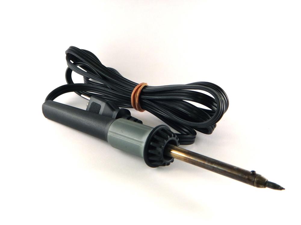
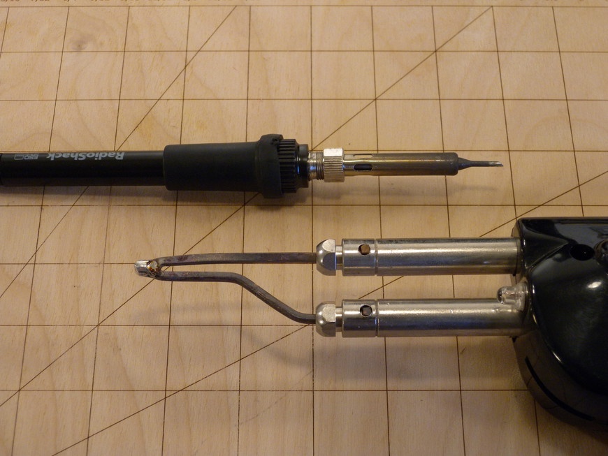
The fixed-temperature soldering iron or “fire starter,” as it’s also known, does not have a method for monitoring tip temperature and is only recommended for light, through-hole soldering (Figure 4-1). Heat is brought to the tip via a mechanically coupled heating element (Figure 4-2).
Fixed-temperature soldering irons are sold based on wattage, which loosely correlates to tip temperature. Some irons feature a wattage selector tip that affords better thermal control. Table 4-1 is a wattage to temperature comparison that helps to illustrate the appropriate iron for the task.
| Wattage | Unloaded Temperature (°C) |
15 | 275 |
25 | 350 |
40 | 400 |
- Soldering Gun
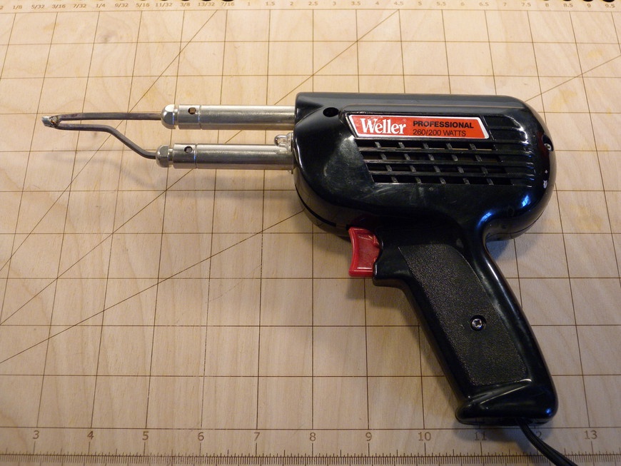
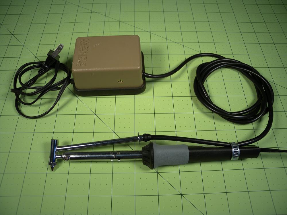
- When soldering components with a large thermal mass, like a large screw terminal or board-mount heat sink, it might be necessary to rely on a “heavy-duty” fixed-temperature soldering iron (Figure 4-3). These irons, also known as soldering guns, apply a large amount of power (200 W) to the tip to bring objects with a large thermal mass up to soldering temperature. Because these irons can reach temperatures in excess of 500°C, it is imperative that the joints be soldered as quickly as possible. Temperature this high will result in irreparable damage to the circuit board and adjoining components.
Adjustable Type
- Actively Adjustable
Adjustable soldering irons use relatively simple technology to control the temperature at the tip and result in a much more consistent and successful soldering experience (Figure 4-4).
Though this type of iron can be more expensive than the fixed-temperature type, the benefits more than make up the difference. Adjustable irons operate by positioning a temperature sensor near the heating element (Figure 4-5). This sensor then sends information to a controller that cycles power to the heater, regulating temperature. More sophisticated controllers utilize a tip selection feature, which provides more accurate regulation by applying a temperature compensation offset, depending on the tip type.
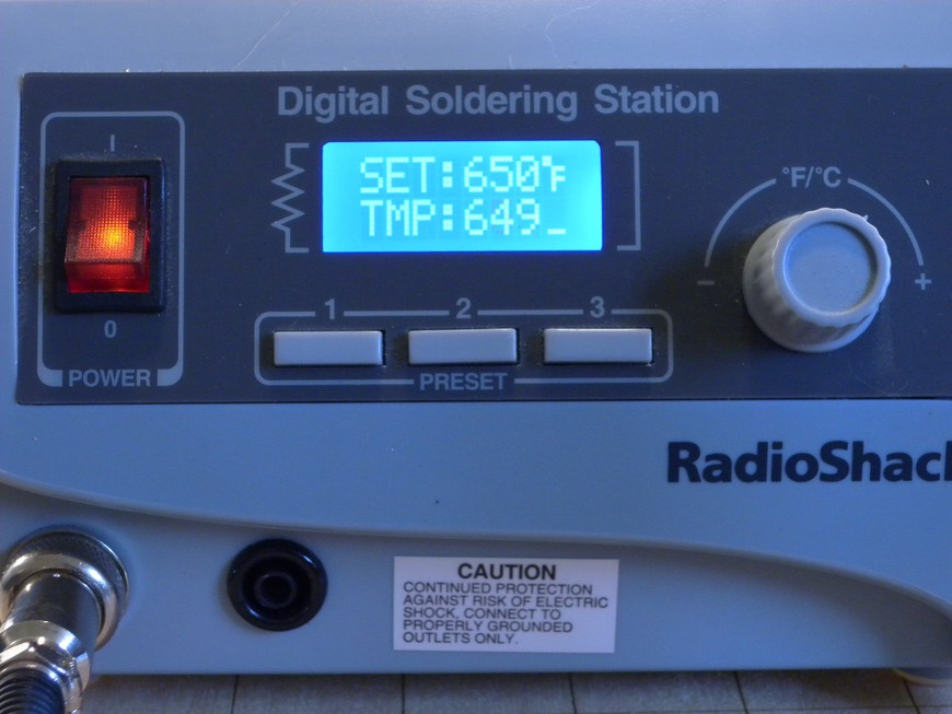
After the desired temperature is selected (Figure 4-6), the controller then sends power to the iron’s heater until the temperature is achieved. This type of iron tends to heat up quicker than fixed-type irons because it utilizes a higher-wattage heater.
- Induction
- An alternative design to the actively adjustable soldering iron uses radio waves to hold temperature (Figure 4-7). This process relies on induction to elevate the tip temperature to the material’s Curie point and provides very stable thermal control. Since it is heated through induction, it takes only a matter of seconds for the tip to reach operational temperature. As the tip actively solders, rather than cool down, the RF input automatically increases the power to the tip and results in a very consistent and efficient soldering experience.
Soldering Iron Tips
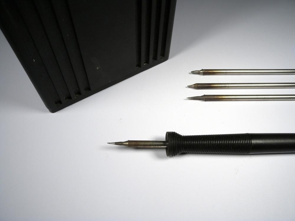
Every soldering iron transfers heat to the solder joint through a thermally conductive tip. This tip acts as a heat pipe, bringing the heat from the iron’s heating element to the end of the tip. Tips (Figure 4-8) are available in a wide array of styles that are designed to meet almost any soldering or desoldering task.
Most tips contain a thermally conductive copper core that is surrounded by a layer of iron. The iron provides the tip with rigidity and the desired solder bonding characteristics. Because iron is susceptible to corrosion, the outer surface of the tip is plated with chrome or nickel and only a small amount of iron is left exposed at the end.
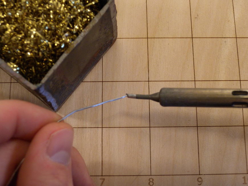
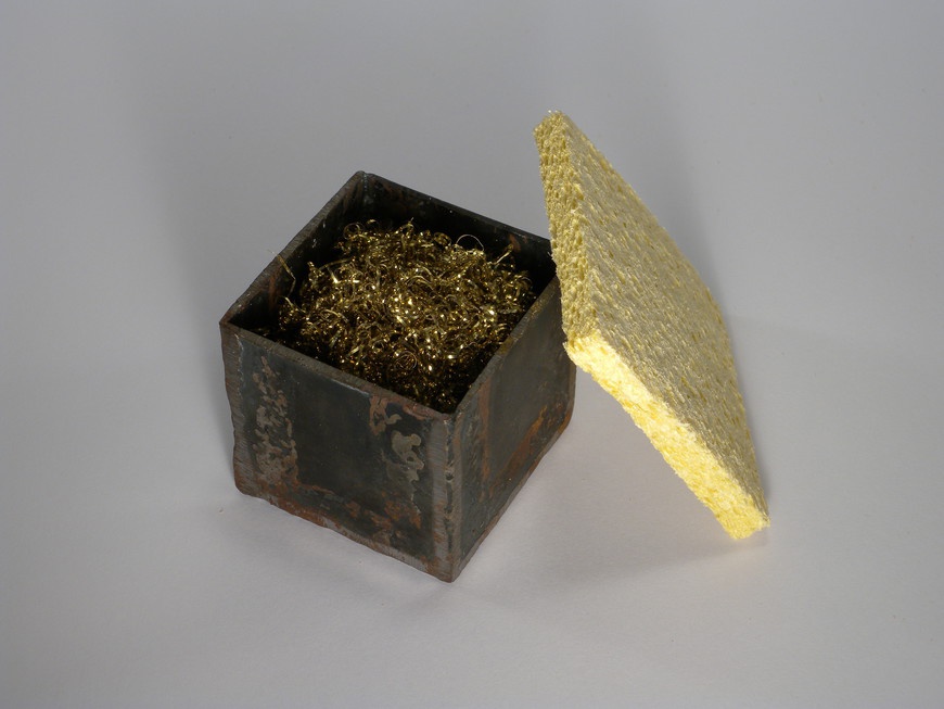
Soldering iron tips can last for years when they are properly maintained. While in operation, the iron jacket is prone to deterioration due to accelerated rusting from the high heat. Adding a small amount of solder to the tip of the iron helps prevent this oxidation and ensures good thermal transfer to the joint. This process, known as tinning (Figure 4-9), also helps to prevent the natural corrosion that occurs when the iron is not in use. To maintain optimal performance, the tip should be cleaned frequently by wiping it on a wet sponge or brass pad (Figure 4-10). This process prevents the buildup of solder and burnt flux, which inhibit good joint formation.
Tip Types
It is important to choose the right tip for the job. Their size and shape dictate how much heat can be carried to the end of the tip. Larger tips are designed to heat up components with a large thermal mass, whereas smaller tips are the opposite. Soldering iron tips can be broken into three types: bevel, chisel, and conical.
- Bevel
- The bevel-type soldering iron tip serves as a good multipurpose solution (Figure 4-11). This tip features a large body diameter that tapers to a small beveled tip, which gives you the ability to perform satisfactory soldering of through-hole as well as some surface-mount device (SMD) components. You can rotate the tip to the side opposite the bevel to solder through-hole, and the tip of the bevel is optimal for soldering SMDs.
- Chisel
- The chisel-type, or screwdriver, tip is most commonly supplied with new soldering irons (Figure 4-12). This tip type is designed to provide a contact area perpendicular to the component, making it ideal for soldering through-hole and larger components.
- Conical
- The conical-type tip is designed to focus the iron’s heat to a very fine point and is optimized for soldering small through-hole and SMD components (Figure 4-13). These tips are prone to deterioration due to their fine point and should be cleaned and tinned regularly.
Project: Solder Holder and Iron Stand
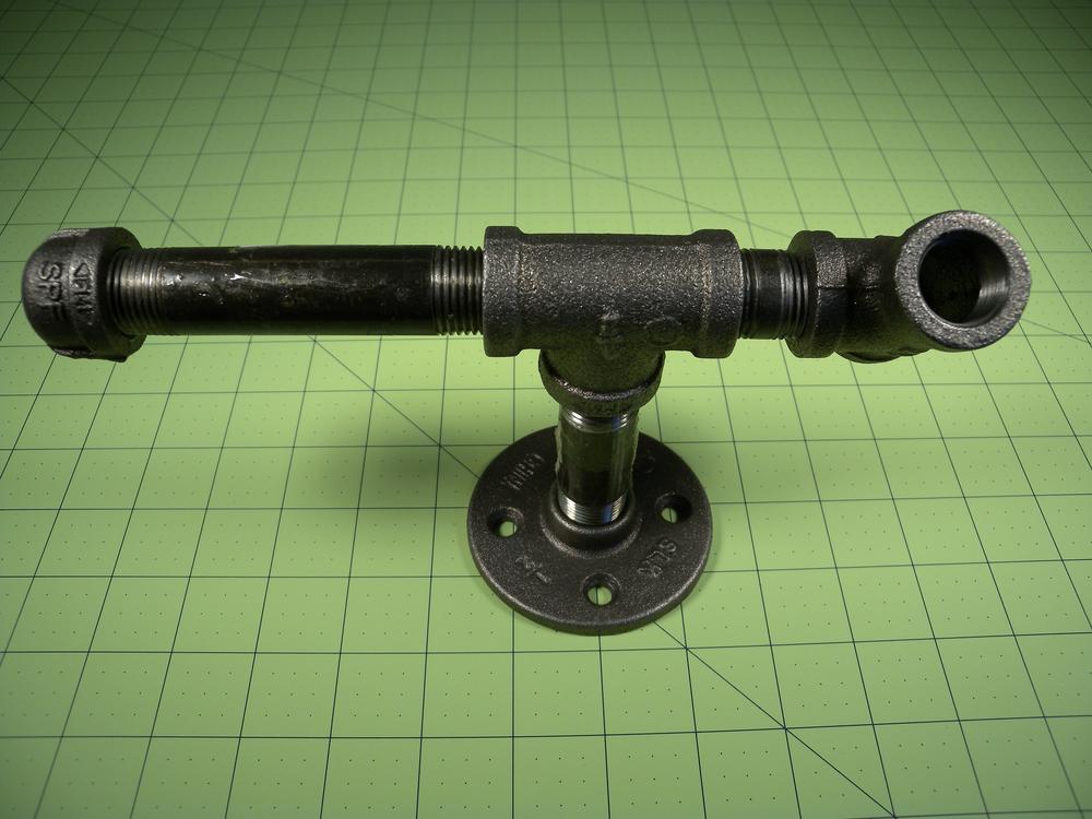
Most soldering irons come with flimsy stands that eventually break and offer little stability. With a quick trip to the plumbing aisle of your local home improvement store, a robust stand can be easily constructed from pieces of iron pipe.
This stand is designed to support a heated soldering iron. Make sure that it is securely coupled to a work surface to ensure that it does not fall over during use.
Materials
| Materials List | ||
Item | Quantity | Source |
1/2 in × 2.5 in iron pipe | 1 | Home improvement store |
1/2 in × 4 in iron pipe | 1 | Home improvement store |
1/2 in iron pipe cap | 1 | Home improvement store |
1/2 in iron pipe flange | 1 | Home improvement store |
1/2 in iron pipe “T” | 2 | Home improvement store |
Procedure
- Step 1
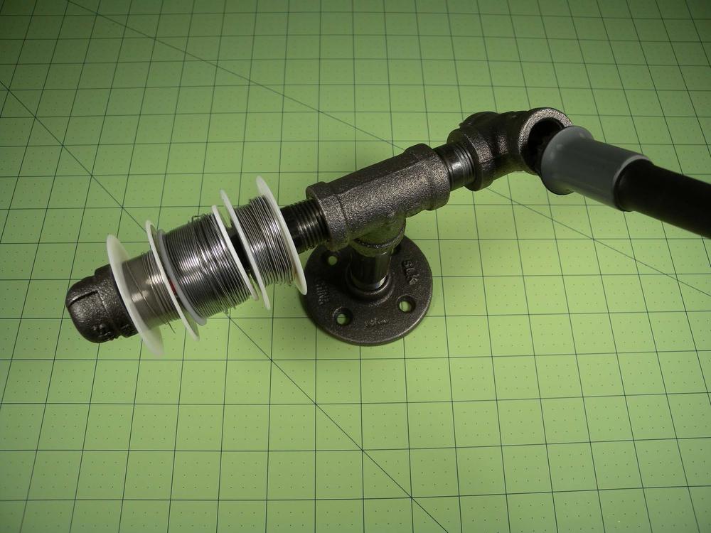
- Assemble the stand as shown (Figure 4-14). Upon completion, use fasteners to mount the stand to the work surface, or to a 12 in × 12 in piece of plywood for a portable installation.
- Step 2
- Congratulations! You have just assembled a robust solder holder and iron stand. With something this simple, there’s no reason every soldering station in your Makerspace should be without one.
Replace the T-junction with a 4-way adapter and screw in a 12 in piece of pipe. This extension can act as a great mount for a work light or magnifying glass. Before attempting this upgrade, ensure that the stand is mechanically coupled to the work surface.
Solder and Flux
There are an amazing amount of solder types, thicknesses, and fluxes available for soldering and desoldering electronic components. Solder is manufactured as either a bar, wire, or paste and can be found with or without flux. Until recently, most solder contained an alloy of a tin/lead or silver/tin/lead because they featured a low melting point and resistance to corrosion (Table 4-2). Now, most modern electronics use a lead-free alloy due to its lower environmental and material handling hazards.
| Process | Alloy | Melting Temperature (°C) | Form | Notes |
Leaded | Sn60Pb40 | 183–190 | Wire & bar | Provides a wide working temperature range and is easy to rework |
Leaded | Sn63Pb37 | 183 | Wire, bar & paste | Most common alloy and exhibits virtually no plastic range, also known as being eutectic |
Lead free | Sn96.5Ag3.0Cu0.5 | 217–220 | Wire, bar & paste | Most common lead-free alloy, provides rapid melting and high joint strength |
When solder is heated and deposited, oxides form on the solder’s surface and inhibit joint formation. This oxidation can lead to erratic circuit behavior or even complete joint failure. The inclusion of solder flux into the process helps to remove impurities from the connection and promotes proper joint wetting.
Do not use soldering flux that is designed for plumbing purposes. It can contain harmful corrosives that will physically damage your circuit board as well as being slightly electrically conductive.
Solder flux is available in three main formulas: rosin-based, no-clean, and water soluble. Each formula offers a wide range of viscosities, from a paste, which is good for tinning wires, to a near water-like consistency. The choice of solder flux reflects personal preference, and making multiple formulas available in your Makerspace is certainly a good way to make everyone happy.
Solder
- Paste
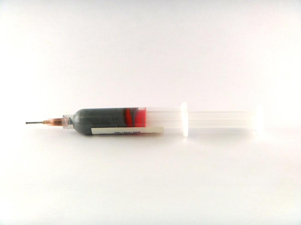
- Solder paste is extensively used for soldering SMD components and comes as a thick grey paste containing tiny solder particles suspended in a volatile flux medium (Figure 4-15). In a process known as reflow soldering, solder paste is applied to the surface of a bare circuit board using stencil and squeegee. The paste then acts as a mild adhesive, holding the components in place prior to the soldering process. When the board, paste, and components are heated, the solder melts and the flux evaporates leaving a precisely controlled solder joint. The advent of solder paste has made possible more complex soldering methods including double-sided circuit boards and pads underneath components (Table 4-3).
| Process | Flux Type | Alloy | Notes |
Leaded | No-clean | Sn63Pb37 | Good general purpose paste |
Lead free | No-clean | SN96.5Ag3Cu0.5 | Slightly more expensive then leaded and requires reflows at a higher temperature |
- Wire
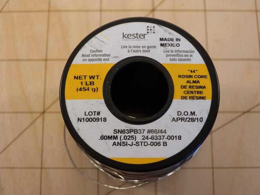
Solder wire is the most common form of solder and is mainly used when soldering components by hand (Figure 4-16). The wire comes in two forms: solid and flux core, which indicates whether the solder contains a core of rosin/flux. Typically, rosin-core solder (Figure 4-17) is preferred as it eliminates the need for manually adding flux while soldering. Solid-core solder is typically used in situations that are sensitive to flux vapors or as per personal preference of the user.
Solder wire comes in a wide range of diameters (Table 4-4), ranging from 0.015 in to 0.125 in and is sold by weight. It is nice to have a range of solder diameters on hand because each lends itself to a different type of soldering.
Flux
- Rosin
- Rosin-based fluxes come in three flavors: nonactivated (R), mildly activated (RMA) and activated (RA). Nonactivated flux, whose production happens to be the project for this section, does not contain any additional acids that would require cleanup after soldering. RMA and RA fluxes contain acid activators that must be removed to prevent damage due to their corrosive nature. Regardless of the formula, rosin-based fluxes leave behind deposits that are difficult to remove. Commercial methods for removal require soaking the completed circuit in a bath of potentially harmful solvents that dissolve away the flux residue. Next, the boards are cleaned with deionized water and then baked to remove remaining moisture. The flux you’ll make in this section’s project can simply be left on the board or cleaned up with isopropyl alcohol and a toothbrush.
- No-Clean
- No-clean flux is a mildly activated flux that does not require removal after soldering. Once the flux dries, it leaves a noncorrosive and nonconductive residue behind that can easily be removed with isopropyl alcohol. As a result, no-clean flux is thin and evaporates quickly, especially if the board is warm.
- Water Soluble
- Water soluble flux is highly activated and can be removed with water. Due to its high acid content, water soluble flux must be cleaned from the entirety of the circuit board before put into operation. This cleaning process involves submerging the circuit board in a bath of deionized water and throughly scrubbing it to remove any residue. A failure to remove 100 percent of the flux can result in erratic operation or even permanent damage to the circuit.
Project: Two-Ingredient Soldering Flux
You really can never have enough flux! As a Makerspace increases in popularity, the need for cost-effective consumables becomes ever more apparent. It just so happens that you can make a lot of flux with just two low-cost ingredients.
One of the nice things about this project is that you can custom tailor the viscosity of your flux by adjusting the rosin-to-flux ratio. Table 4-5 illustrates ratios that I have found to work well for the given situation.
| Rosin (g) | Alcohol (mL) | Result |
1 | 1.9 | Thick |
1 | 2.4 | Standard |
1 | 3.0 | Thin |
This project requires safety glasses that should be worn throughout its entirety.
Materials
| Materials List | ||
Item | Quantity | Source |
Air-tight glass jar | 1 | Grocery store |
>90% isopropyl alcohol | 1 | Grocery store |
Natural rosin crystals or equivalent | 1 | Musical instrument supplier |
Coffee filter | 1 | Grocery store |
Scale | 1 | Grocery store |
Graduated cylinder or equivalent | 1 | Scientific supply store |
If natural rosin is not available, musicians’ rosin makes a good alternative. You can find it at any local music store.
| Makerspace Tools and Equipment |
Hammer |
Safety Glasses |
Procedure
- Step 1
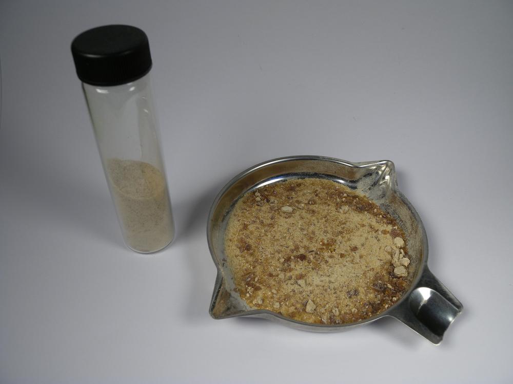
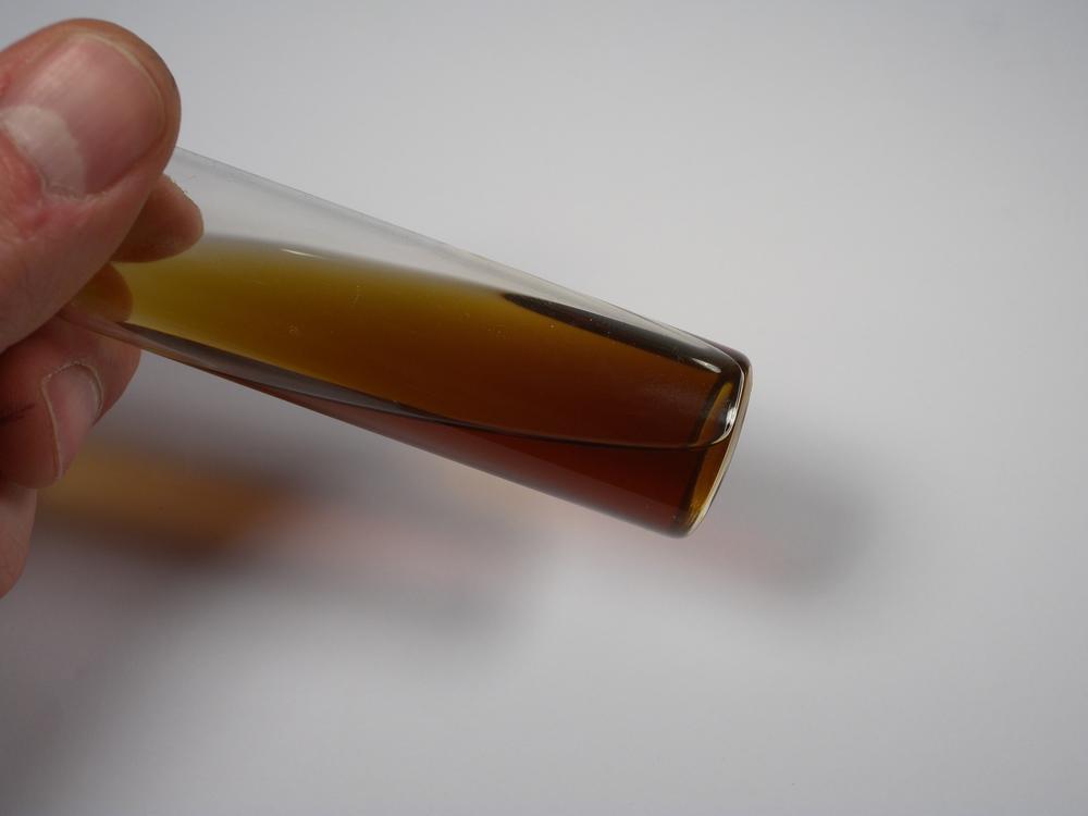
- Start by weighing out the predetermined amount of rosin onto a piece of paper (Figure 4-18). Take the rosin out of the packaging and wrap it in a piece of paper. Put the bundle in a sturdy plastic bag and pulverize with a hammer. The finer you pulverize the rosin, the quicker it will absorb in the alcohol.
- Step 2
- Determine your desired viscosity, measure out the appropriate amount of alcohol as shown in Table 4-5, and then add it to the jar. Carefully pour the crushed rosin into the jar and seal the lid. Ensure that the lid is on tight because the alcohol can evaporate quickly. Gently swirl the mixture until the rosin is fully dissolved. Let the mixture sit for a few hours or overnight until complete.
- Step 3
- When the rosin has fully dissolved into the mixture, place the funnel and coffee filter into the second jar. Carefully pour the initial mixture through the filter and into the second jar. This process eliminates any large particles that might hinder your soldering (Figure 4-19). After soldering, clean up flux residue with isopropyl alcohol, flush the board with distilled water, and then dry it using compressed air.
Through-Hole Soldering
Through-hole soldering is the most common type because it’s not difficult to learn and doesn’t require exotic soldering equipment. Through-hole describes the mounting configuration of an electronic device containing one or more leads. These leads are configured such that a solder connection can be made on the side of the circuit board opposite that of the component. Their relatively large size, easy handling, and ability to be used with a breadboard has made through-hole components the backbone of most Maker projects and pre-production prototypes.
There are two types of circuit boards to which through-hole components are commonly mounted mounted: single-sided and multilayer.
Single-sided circuit boards (Figure 4-20) contain copper on only one side of the board and are commonly found in hobbyist projects and low-cost electronics. Having copper on only one side simplifies the design and facilitates easy creation by using the toner-transfer method. Single-sided circuit boards are also significantly easier to rework because the solder only needs to be removed from one surface.
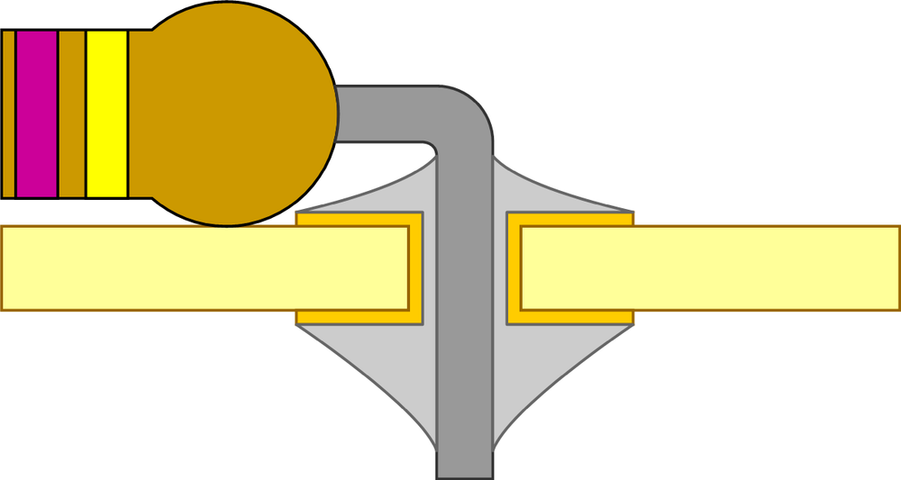
Multilayer boards (Figure 4-21) contain two or more layers of copper attached to the circuit board material. This configuration makes it possible for circuits to take up less surface area because the traces and planes can overlap on the subsequent layers. When soldering through-hole components on multilayer boards, the solder pad typically has two sides: one pad on the top, and one on the bottom of the board. Connecting the layers is a hole plated with conductive material, usually copper or tin. The advantage of using multilayer circuit boards with through-hole components is the added structural integrity provided by the increased surface area.
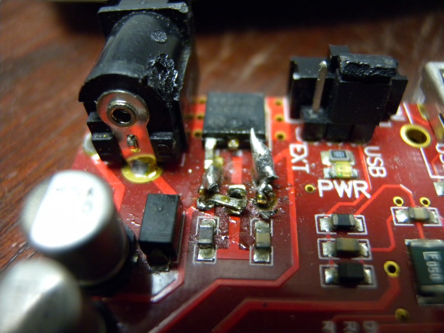
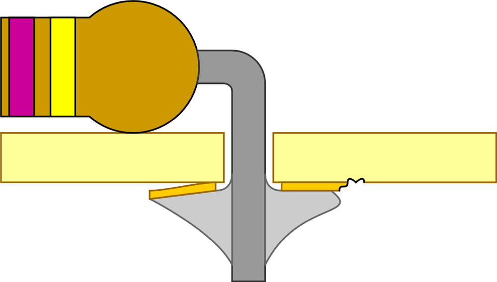
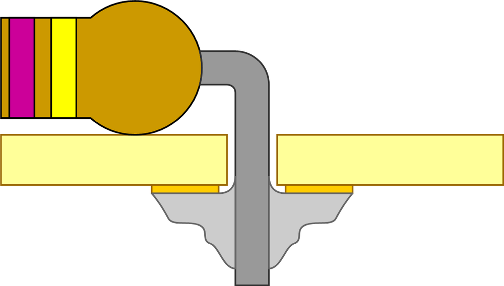
The added thermal mass of pads that connect to each side of the board make components difficult to desolder, especially if they are attached to a ground plane. Often excessive heat applied during this process results in damage to the component or de-lamination of the pad (Figure 4-22).
Identifying Poor Through-Hole Solder Joints
Amateurs and skilled solder technicians alike have at some point made improper solder joints or have even damaged their circuit board. This occurs as a result of overheating the solder joint, adding too much or too little solder, or producing a cold solder joint.
- Overheated Joint
- Overheated joints are the most common mistake made by beginners when learning to solder (Figure 4-23). This occurs when the soldering iron is applied to the joint for too long, resulting in the physical damage of the circuit board or adjoining components. Depending on the severity of the damage, the joint can be corrected by removing any excess solder, letting the circuit board cool, cleaning the area, and fixing the damage with fresh solder. If a pad has been lifted or a trace has been broken, it can be easily fixed with the aid of a jumper wire.
Use PTFE-coated wire-wrap wire to fix broken traces because the high temperature coating makes the job easy. An alternative is to use the leads of a resistor. Bend the leg at a 90-degree angle in the length that is required and use the resistor as a handle when soldering in place. Trim off the excess lead and the fix is done!
- Cold Solder Joint
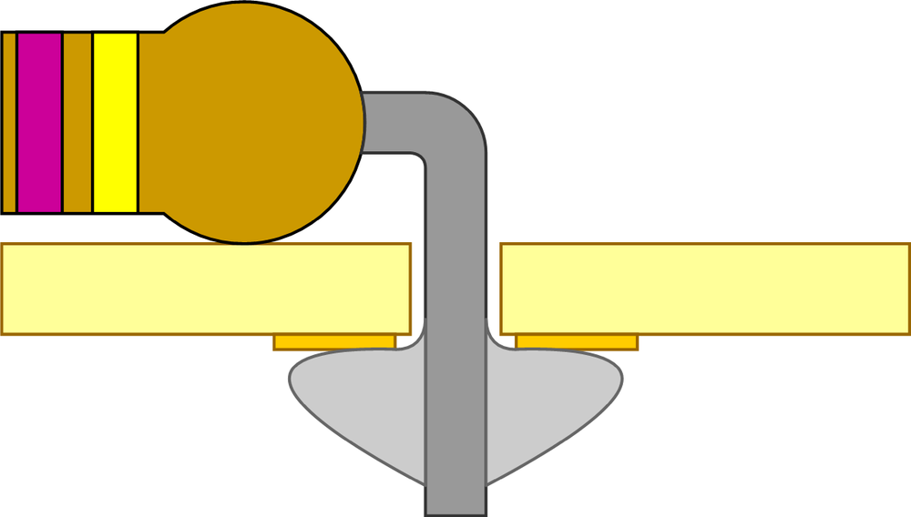
- Cold solder joints occur when the solder is not elevated to a high enough temperature or the joint is disrupted while cooling (Figure 4-24). This results in a drastically weakened joint that will perform unreliably or fail entirely. There are two ways to fix a cold solder joint. First, additional flux can be added to the joint and corrected by simply reapplying the soldering iron again until the joint wets. Second, the joint can be reformed by removing the solder from the joint and applying fresh solder.
- Too Little Solder
- Applying too little solder to the joint is also a very common mistake (Figure 4-25). This problem isn’t as obvious in appearance as it sounds and the resulting joint can actually look correctly formed. The mistake occurs when the pin and pad are unevenly heated. When solder is applied to the joint, it only wets one of the connections rather than both. To fix this problem, reapply heat to the joint so that both the pin and pad are sufficiently heated and then apply a small amount of new solder. The result should be a shiny convex fillet. If the joint looks dull or misshapen, let it cool, apply a small amount of flux, and reapply your soldering iron until the joint has the desired appearance.
- Too Much Solder
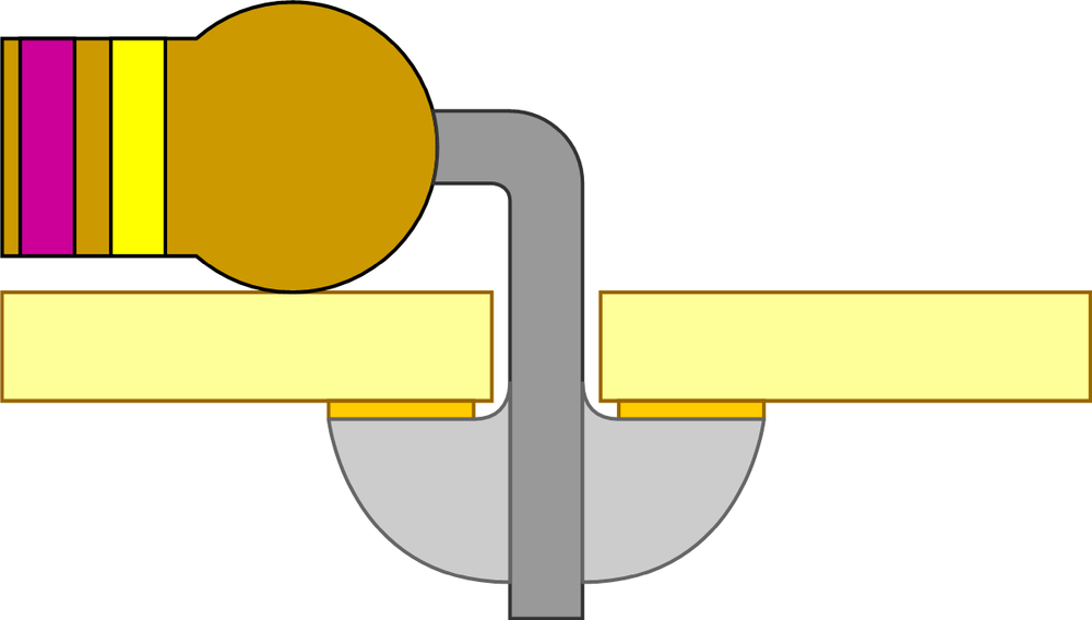
- Applying too much solder is another very common mistake (Figure 4-26). The result is anywhere from a convex blob to a small sphere of solder around the pin and pad. Although this problem does not necessarily affect the performance of the joint, it can lead to electrical shorts with nearby components and doesn’t reflect good soldering etiquette. There are two good ways to fix this problem. First, remove the excess solder by using desoldering braid or a vacuum gun, let the joint cool, and then re-apply an appropriate amount of solder. Second, trim the components pin up to the joint, invert the circuit board so that the solder joint is facing the ground, and then carefully apply your soldering iron to the joint. If you are successful, gravity should transfer the excess solder to your iron.
Soldering Technique
I started soldering when I was in elementary school, building through-hole projects from schematics found in books and with the help of a cheap, unadjustable soldering iron. This iron provided me with a rather unpleasant soldering experience, leaving my circuit boards riddled with scorch marks and questionable solder joints. It wasn’t until I completed four or five circuits that I realized the importance of the relationship between solder, temperature, and time.
Most solder used for soldering electronics contains a small quantity of solder flux. This flux is designed to prepare the contact surfaces by removing impurities and assisting in the proper wetting of the joint. A proper solder joint is formed by introducing enough heat to the junction between the pin and pad and applying a small amount of solder.
A good rule of thumb when soldering is to complete the joint in under three seconds. This “three-second rule” helps prevent damage to the circuit board and component as well as provides ample time to create a proper joint. If you have not completed soldering the joint in less than three seconds, let the joint cool and then try again. Achieving a properly soldered through-hole joint is not a difficult task. If you understand the variables required to successfully solder a joint and follow the “three-second rule,” you should be off and running in no time.
Properly soldered through-hole joints should be concave in shape and should completely wet the pin and pad. These traits illustrate that the joint was made with proper technique and will result in a long-lasting electrical connection.
Materials
| Materials List | ||
Item | Quantity | Source |
Perforated circuit board | 1 | Electronics supply store |
Misc. through-hole components | 1+ | Electronics supply store |
| Makerspace Tools and Equipment |
Circuit board vise |
Safety glasses |
Snips |
Soldering iron and stand w/ sponge |
Solder wire |
Proper Through-Hole Soldering
This project requires that safety glasses be worn throughout its entirety.
- Step 1
- Pass the pins of your through-hole component through their respective holes so that the component is located on the appropriate side of the board (Figure 4-27). Components with long leads, such as resistors, can be held in place by gently bending the leads to the side, or by securing in place with a piece of tape.
- Step 2
- Check whether the soldering iron has reached temperature by applying a small amount of solder to its tip (Figure 4-28). If the solder quickly melts, it has reached temperature, and you can clean the now tinned tip with the sponge. Gently press the iron in the root of the joint so that you evenly heat the pin and pad. Using your free hand, carefully apply enough solder to the joint to sufficiently wet the pin and pad, resulting in a slightly convex fillet. Remember, this entire process should take three seconds or less. If you are soldering a through-hole component to a multilayer circuit board, ensure that the solder completely flows through the plated hole and wets the component side pin and pad with a slightly convex fillet of solder.
Project: Simple Constant-Current LED Tester
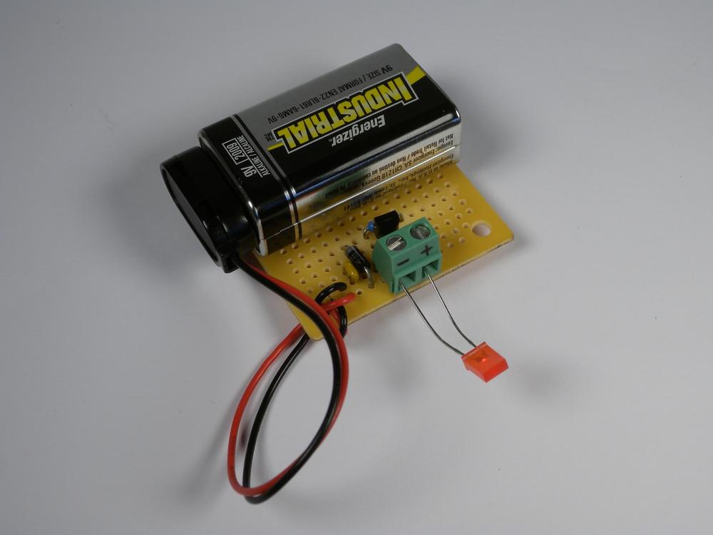
There are many ways to test whether an LED is functional. You can use a multimeter, a power source, and single voltage-dropping resistor, or with a constant-current power supply. Although each of these accomplish the same general task, it is always nice to have a dedicated piece of hardware. This project (Figure 4-29) illustrates the fundamentals of through-hole soldering through the construction of a constant-current LED tester that can be mounted onto a 9-volt battery with just a couple of components.
This circuit (Figure 4-30) is designed around the popular LM317 adjustable voltage regulator and allows for the quick testing of through-hole LEDs. The LM317 regulator operates by using a voltage feedback loop to regulate output voltage by burning off excess voltage in the form of heat. It can be easily configured as a constant-current power supply that uses its voltage-regulating ability to automatically adjust the output voltage based on current consumption. If desired, the circuit can be modified as an adjustable constant-current supply by adding a potentiometer in series with R1.
Here’s how to calculate the constant-current supply:
(1.25 V / R1) * 1000 = IF
If the LED has an IF (LED Forward Current) of 15 mA:
(1.25 V / R1) * 1000 = 15 mA
or:
1.25V / (15 mA / 1000) = R1
R1 = 83.3 Ohms
For this circuit, the current will be limited to ~15.6mA by using an 80 Ohm resistor.
Materials
| Project Materials List | ||
Material | Qty | Source |
0.1 uF Capacitor | 1 | Electronics supply store |
1N4001 Rectifier diode | 1 | Electronics supply store |
5 mm LED | 1 | Electronics supply store |
~80 Ohm resistor | 1 | Electronics supply store |
9 V Battery | 1 | Electronics supply store |
9 V Battery snap connector | 1 | Electronics supply store |
LM317 (TO92 package) | 1 | Electronics supply store |
Perforated circuit board | 1 | Electronics supply store |
Screw terminal (2 position) | 1 | Electronics supply store |
| Project Tools List |
Soldering iron |
Soldering iron stand |
Solder wire |
Solder sponge |
Wire snips |
PCB holder |
Double-sided tape |
Masking tape |
Procedure
- Step 1
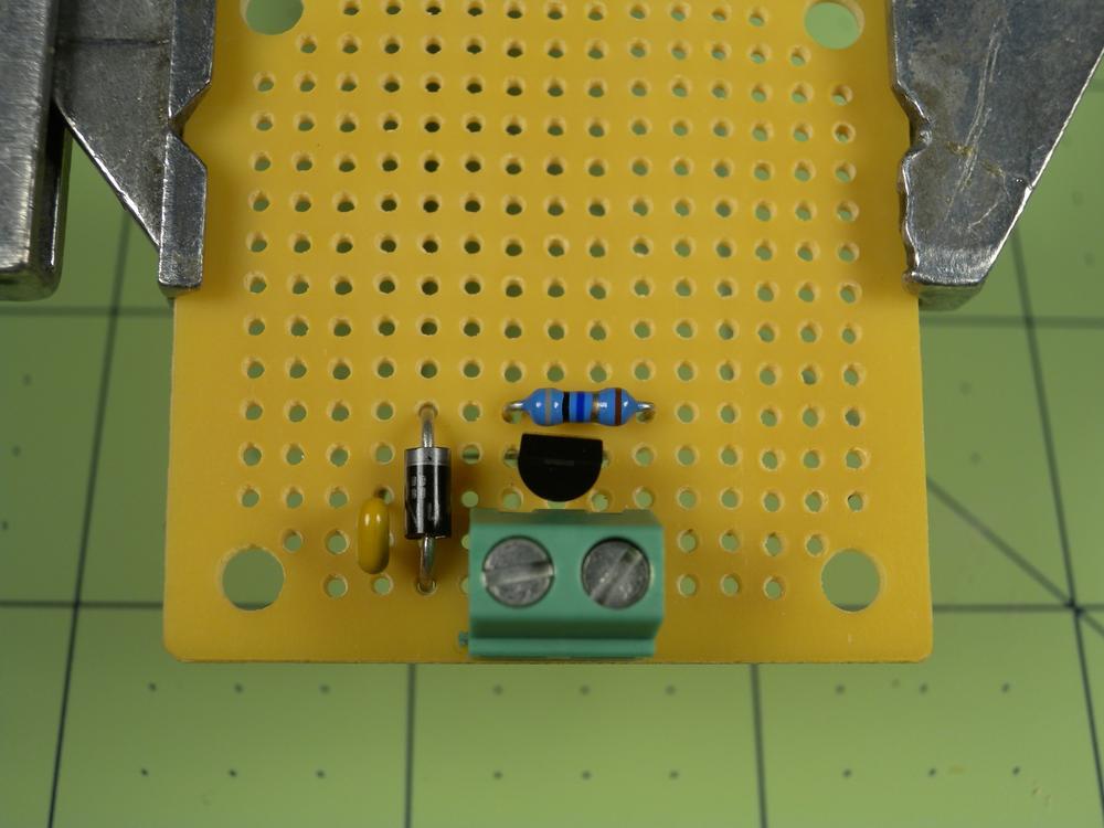
- Start by mounting the perforated circuit board in your circuit board holder, insert the components as shown, and then secure in place with a small piece of masking tape (Figure 4-31). Alternatively, you can carefully bend its legs to the side to prevent the component from falling out. Flip the circuit board over and carefully solder the leads in place. Trim the excess leads when complete.
- Step 2
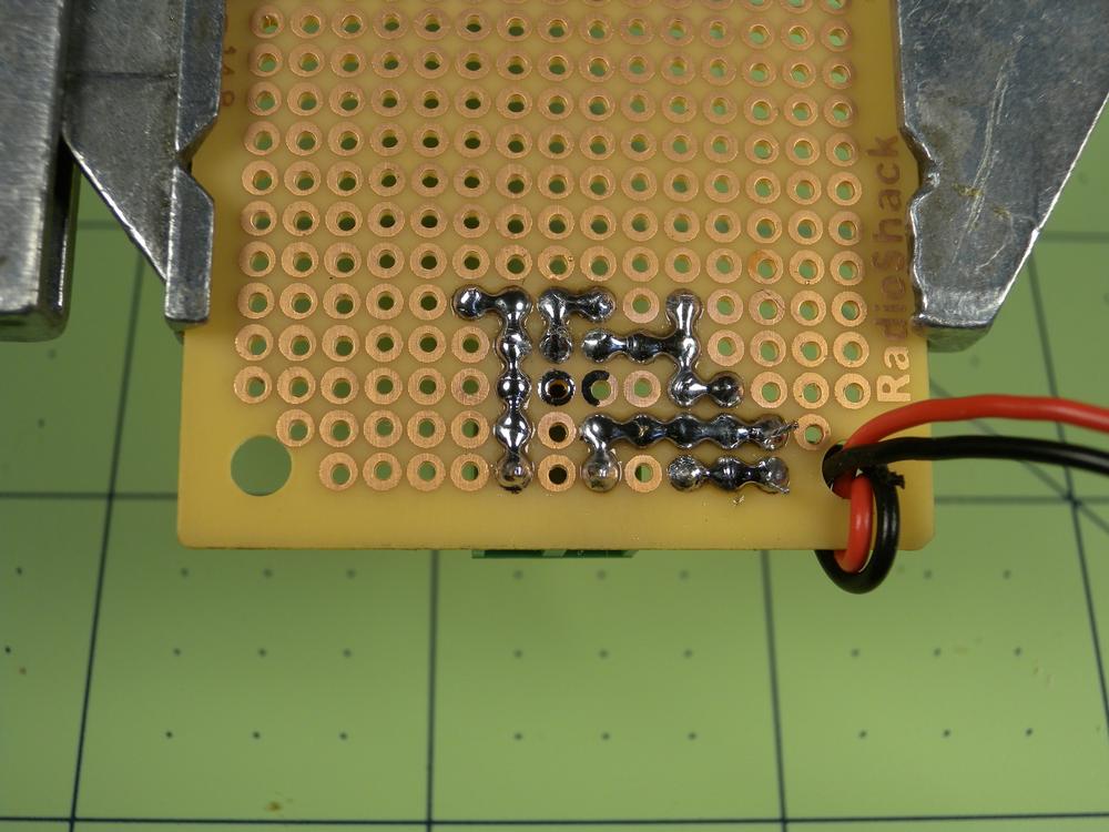
- With the solder side up, connect the components together by carefully bridging the circuit board’s pads with solder (Figure 4-32). This technique is more reliable than using wires to make the connections, which tend to fatigue and brake with repeated handling. If you accidentally make an unwanted connection, let the board cool for a few seconds and then use the soldering iron to gently remove the unwanted solder.
- Step 3
- Solder on the battery snap’s leads to the illustrated position and mount the battery in place using double-sided tape. Congratulations! You have successfully assembled your LED tester, and now it’s time to power it up and test some LEDs!
- Troubleshooting
If the power LED doesn’t light up when the battery is connected:
- Check that the battery has sufficient voltage.
- Check the orientation of the LED; it might be installed backward.
- Check the orientation of the rectifier diode; it might be installed backward.
If the LM317 gets really hot:
- Check that your input voltage is not over 10 volts.
- Check the orientation of the LM317; it might be installed backward.
The tested LED does not light up:
Surface-Mount Soldering
As your skills develop and the projects gain complexity, you will find the need for higher levels of soldering skill to properly mount the components. At first, it might seem that surface-mount soldering takes an unobtainable level of discipline and skill. But as with anything, practice makes perfect, and you will soon find that it really isn’t any harder than soldering through-hole. The world of surface-mount soldering is exciting and fun and when you get the hang of soldering those tiny components, you will be able to transform your projects into smaller and more robust forms.
Surface-mount, or SMD, components (Figure 4-33) are the primary type of component found in commercial electronic devices. As electronics become more efficient, produce less heat, require less voltage and as manufacturing capability improves, the size of components decrease. This saves both materials and cost while simultaneously affording higher-density layouts. A good example of this forward progression is illustrated when comparing the early room-sized computers of the 1970s to the multicore-powered phones of today.
Each SMD component contains a series of small leads or contacts that are the electrical connection to the circuit board. This design differs from through-hole components because they tend to take up more space and require their leads to pass through the circuit board. Surface mount components are purchased on reels or as cut-tape (a cut section of a reel). This format makes it possible to feed surface-mount components into machines that pick and place the components onto prepared circuit boards using sophisticated imaging and control technology.
Make sure to thoroughly read the specification sheet for your components because their power rating often decreases with size. You don’t want to use a component that isn’t properly rated; it is likely to fail or might even catch fire.
As projects are refined, it often makes sense to convert the design to use surface-mount components. The sizes of these components vary greatly, so when you are just starting out, go with the “big” ones. Table 4-6 presents some common components that are good for beginners and their package sizes.
| Package | Component Types | Lead Spacing (in) |
0805 | Resistors, ceramic capacitors, LEDs | 0.080 |
1206 | Ceramic capacitors, diodes, shunts | 0.120 |
SM-A | Tantalum capacitors | 0.126 |
DPAK | Voltage regulators, power diodes | 0.180 |
SOIC | Microcontrollers, EEPROMs and other general integrated circuits | 0.050 |
As your skills increase, you will find that you can handle even smaller components. This will lay the groundwork toward making smaller and more dense layouts in addition to reducing component and material cost. Table 4-7 lists some common components and their package sizes that are good for more advanced technicians.
| Package | Component Types | Lead Spacing (in) |
0603 | Resistors, ceramic capacitors, LEDs | 0.060 |
SOT23 | Transistors, diodes | 0.075 |
SOT23-5/6 | Voltage regulators, microcontrollers | 0.037 |
SSOP | Microcontrollers, EEPROMs and other general integrated circuits | 0.025 |
QFP | Microcontrollers | 0.026 |
Each of the aforementioned package types require a slightly different method for proper soldering. You can solder some components by hand with the assistance of one or two soldering irons, whereas others, like the BGA package, require more complex methods.
Identifying Poor SMD Solder Joints
The occurrence of improper solder joints is even more prevalent with SMD components. These problems often go unnoticed due to the joint’s small size and obscurity, but they are identical to those found when soldering through-hole. Unfortunately, they are also more complicated to resolve. With your magnifying glass in one hand and iron in the other, you can easily identify and eradicate them.
- Cold Solder Joint
- The occurrence of cold solder joints on SMDs is relatively low due to the heavy use of flux (Figure 4-34). Even still, there are times when a joint doesn’t properly form and rework is necessary. To fix the problem simply apply a small amount of flux to the joint and resolder.
- Overheated Joint
- Many surface mount components feature pins and pads that are a fraction of a millimeter wide (Figure 4-35). This small amount of material is easily overheated and damaged if the soldering iron drags across the surface. These joints can be fixed by removing the excess solder with desoldering braid and clearing away any circuit material by using alcohol. Continue to solder the rest of the component’s pins, and when secure, repair the broken pin/pad using a small piece of wire-wrap wire.
- Too Little Solder
- Solder joints with too little solder are hard to detect on through-hole components and are virtually impossible to detect on SMDs without magnification (Figure 4-36). These joints occur when the solder does not properly wet the junction between the pin and the pad, causing a small gap to form. To remedy the problem simply apply a small amount of flux to the joint and solder it again. Alternatively, you can fix the problem by gently pressing down on the pin with the soldering iron until the pin and pad properly join.
- Too Much Solder
- It is very easy to create solder bridges when soldering SMDs. Happily, there are two good ways to solve this problem (Figure 4-37). First, continue to solder the remaining pins to secure the part and, when secure, apply a small amount of flux to the solder bridge and wick it away with the tip of a clean soldering iron. Because the soldering iron likes to bond to solder, it will suck up the tiny amount of solder left on the pins. The second method utilizes conventional soldering braid. This method is recommended as a last resort only because the mechanical contact of the braid and soldering iron can damage the pins. To remove excess solder with the braid, start by tinning it with a small amount of solder and lay it on top of the pins. Using the side of the soldering iron tip, gently press down on the braid until it wicks away the unwanted solder.
Hand-Soldering SMDs
I learned my technique for soldering SMD components from a technician who makes her living by hand-soldering $75,000 computer chips for the space industry. This is quite a feat to witness, and her ability to do so with gracefully steady hands is awe inspiring. Even though she has multiple thousand-dollar soldering irons and a fleet of tips at her disposal, she is able to accomplish most of her tasks with just two irons outfitted with her favorite tip. The reality is, you do not need multiple rooms full of thousand-dollar irons to begin surface-mount soldering. A pair of adjustable irons costing less than $100 can provide plenty of capability and doesn’t strain the budget.
This section focuses on two soldering iron techniques: single-iron and dual-iron. Single-iron technique is good for attaching new components to untinned pads because you rely on the absence of solder on one side to keep the component flat while soldering. Dual-iron technique works well for all components with two or more pins and aids in reworking components.
Set the iron’s temperature to 371°C/ 700°F and adjust slightly, depending on the type of part you are soldering. If I am soldering a joint that is coupled to the ground plane, I bump the temperature up a bit to accommodate for the added thermal mass, and vice versa. Also, don’t forget the “three-second rule” (Soldering Technique)!
Materials
| Materials List | ||
Item | Quantity | Source |
Test SMD circuit board | 1 | Electronics supply store |
0805, SOIC, and DFN SMD Components | 1+ | Electronics supply store |
| Makerspace Tools and Equipment |
0.015 in diameter solder wire |
Adjustable soldering irons w/ chisel tips |
Circuit board vise |
Safety glasses |
Snips |
Soldering iron stands w/ sponges |
Tweezers |
Single-Iron Technique: 0805 Package
This project requires that safety glasses be worn throughout its entirety.
- Step 1
- Secure your board to the work surface. A soldering vise comes in handy here, but work with what you have. The first component will be a 0805 resistor. These resistors are nice to work with due to their relatively large size and lack of polarity.
- Step 2
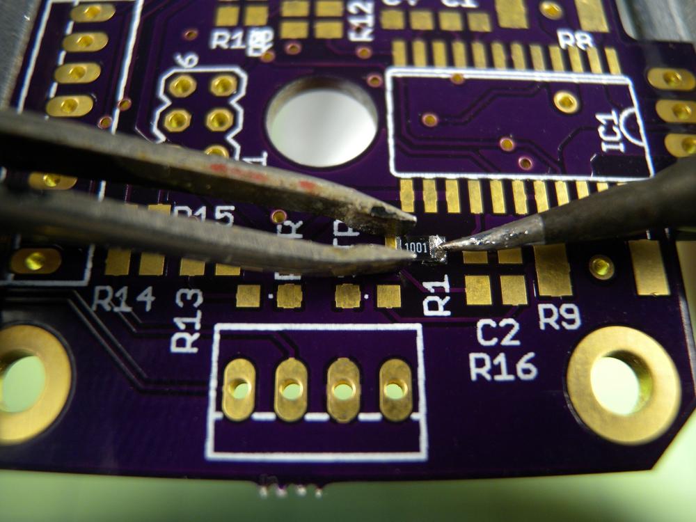
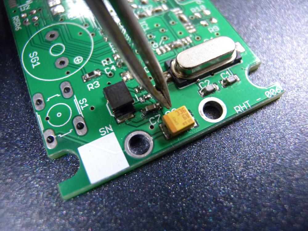
- Apply a small amount of solder to one of the pads (Figure 4-38). If you have the choice between a ground or nongrounded pad, choose the nongrounded because they tend to sink a lot of heat. Carefully pick up the resistor with your tweezers and position it in line with the solder pads. With you free hand, heat up the solder and the resistor’s contact until they are wet.
- Step 3
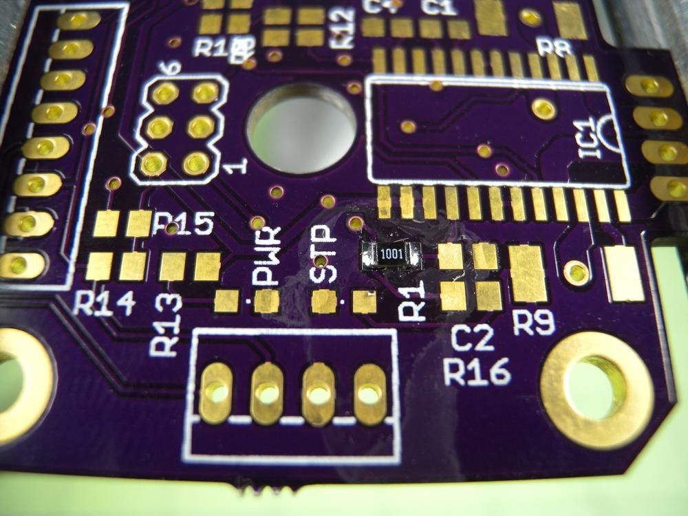
- Using a small amount of fresh solder, solder the second pad (Figure 4-39). Apply a small amount of solder to the first joint and sweep away the excess. This will help to produce a nice, shiny joint (Figure 4-40). Optionally, you can add flux to the joint and touch up with the soldering iron.
Single-Iron Technique: SOIC Package
This project requires that safety glasses be worn throughout its entirety.
- Step 1
- The next component will be an SOIC package EEPROM (Figure 4-41). This package type is nice because the leads have relatively large spacing. Apply a small amount of solder to one of the pads. Use pads on the corners and make sure that it is nongrounded. Upon completion, apply a small amount of flux to the remaining pads. This will facilitate quicker wetting of the remaining joints.
- Step 2
- Using the tweezers, position the component above the respective pads, observing the pin location indicator. Heat up the lead and pad with the iron until they bond, ensuring that the component is properly aligned. If it is not, reheat the joint and align accordingly.
- Step 3
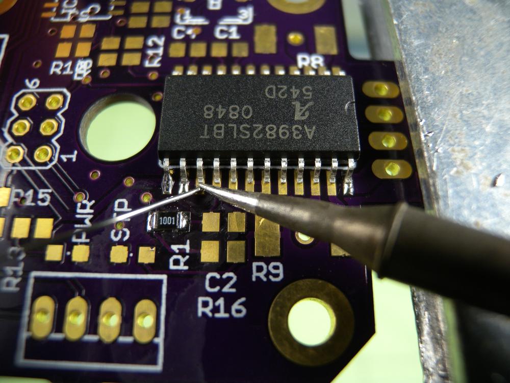
- Solder a lead on the opposite side of the component by placing the soldering iron to the side of the lead so that it touches both the lead and the pad (Figure 4-42). Then, add a small amount of solder to the opposite side of the lead until the solder sufficiently wets the joint. Be careful not to heat the adjoining lead so that you avoid the risk of bridging them with solder. Soldering this opposing lead helps to hold the component in place while you solder the rest of the leads. Don’t worry if the first two joints are not perfect; you will be cleaning them up at the end. Carefully solder the remaining leads and clean up any poorly made joints after applying a small amount of flux.
Single-Iron Technique: DFN Package
This project requires that safety glasses be worn throughout its entirety.
- Step 1
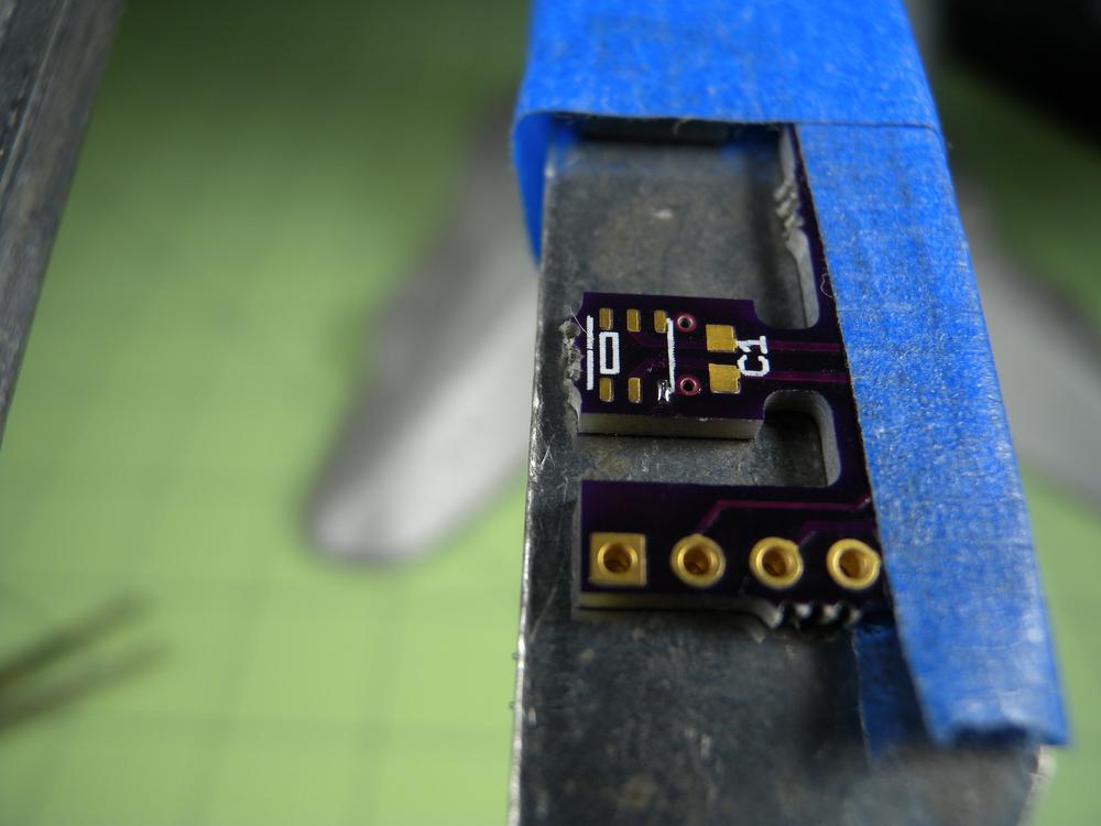
- The final component you’ll solder will be a DFN (Figure 4-43). This package is designed to be soldered via the reflow process and often has an exposed pad on the bottom of the component that requires some fancy footwork to solder. These pads are usually connected to ground and can sometimes be excluded. But check your datasheet just in case! Start by adding a small amount of solder to one of the nongrounded corner pads.
- Step 2
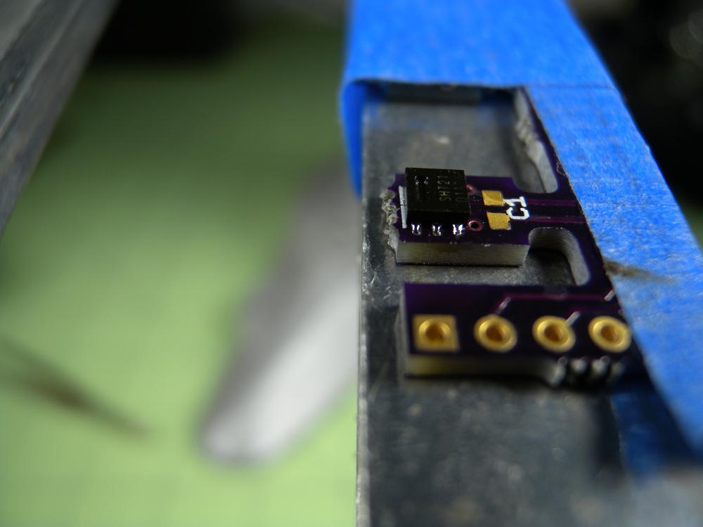
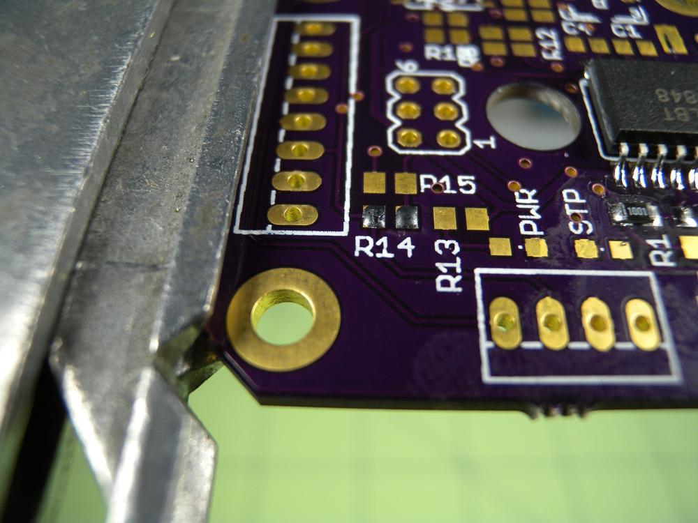
- Upon completion, apply a small amount of flux to the remaining pads (Figure 4-44). Using tweezers, hold the component in place above the respective pads, observing the pin location indicator. Carefully heat up the pin and pad until the solder fully wets the joint. Continue to solder the remaining joints, beginning on the opposite side of the component to prevent overheating.
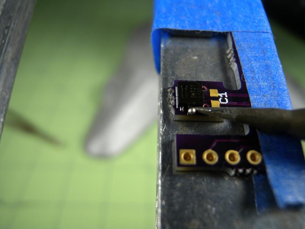
If you are having trouble getting the contacts on a QFN or DFN to sufficiently wet, try dragging a ball of solder across the contacts after you have applied a new layer of flux (Figure 4-45). The surface tension of the solder ball should prevent bridges and encourages an even distribution of solder. Just be careful you don’t overheat the part!
Dual-Iron Technique
This project requires that safety glasses be worn throughout its entirety.
- Step 1
- The first component will be the same type of 0805 resistor used with the single-iron method (Figure 4-46). Begin by applying a small amount of solder to both of the pads. Ensure that there is an even amount of solder deposited. If it is uneven, quickly swipe the tip of the soldering iron across the pads to wick away any excess solder. Place the resistor close to the prepared pads for easy access.
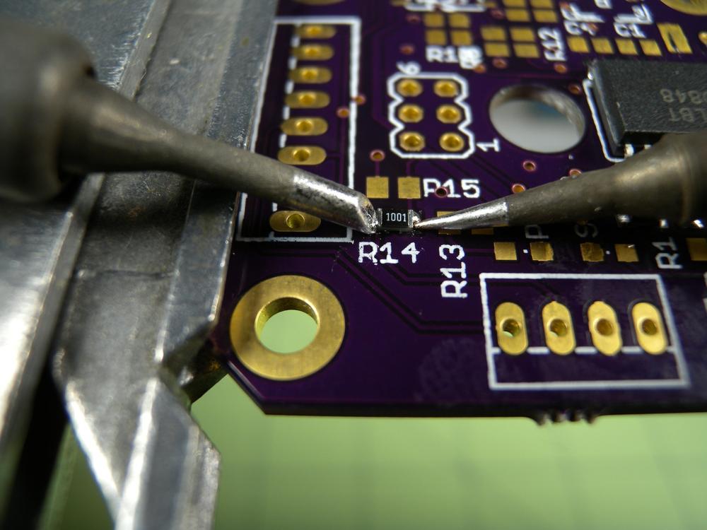
- Step 2
- Using the tips of the soldering iron, quickly lift the resistor and place on top of the prepared pads (Figure 4-47). During this action, the solder on the pads should reheat and wet the resistor’s contacts. Align the component and remove the irons simultaneously. If you find that the part shifts when you remove the irons, you can try removing one at a time. Often times one side will solidify before the other as a result of inconsistent temperature. Apply a small amount of flux to the component and clean up the joints with a quick swipe of the soldering iron.
Reflow Soldering SMD Components
Hand-soldering surface-mount components is a great way to make small projects with relatively high complexity. But, there might come a time when you will need to make higher quantities of boards or have the need to use component packages with contacts that are physically impossible to hand solder. In this case, the reflow soldering method is the way to go. This method utilizes sophisticated equipment and processes to deposit a conformal layer of solder onto one or both sides of a circuit board. It then systematically places and aligns all of the desired components. The freshly populated board is then placed in a temperature-controlled oven in which the board is taken through a series of thermal cycles that are designed to properly wet the solder joints and burn off any impurities. The result is a populated circuit board with highly consistent solder joints.
Reflow Soldering Equipment
- The Solder Stencil
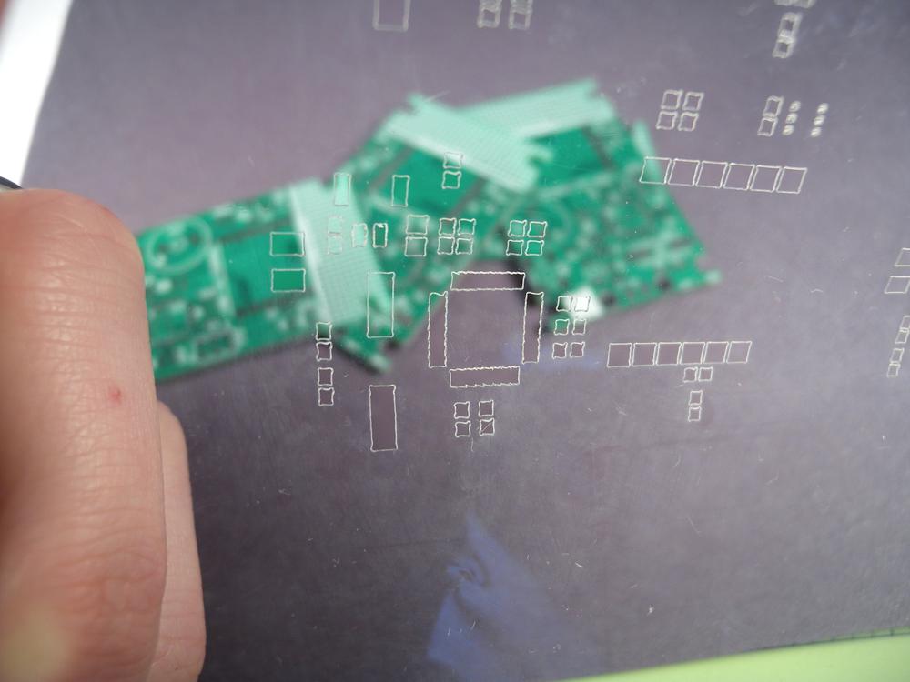
- The solder stencil is responsible for masking the areas around each solder pad and making it possible for a small layer of solder paste to be deposited onto the pad (Figure 4-48). The quantity of solder is dependent on the size of the cutout and the thickness of the stencil. Typically, hobbyist stencils are made out of mylar because it can be cut on a laser cutter. This material accommodates the proccessing of multiple panels of boards before any noticeable damage to the stencil occurs. In industry, stencils are made out of thin stainless steel. This sheet is etched in a process similar to the photo-lithographic method used to manufacture circuit boards or can even be cut with laser. The advantage to metal stencils over mylar is the precision of the cutouts, with metal stencils providing a much more accurate deposition of solder paste in addition to the added durability.
You can purchase inexpensive mylar solder stencils online at retailers like Pololu and OHARARP LLC.
- Solder Paste
- Solder paste is essential to the reflow process (Figure 4-49). Depending on the type of components and environmental conditions, there are a number of types of solder paste from which you can choose. Choose a paste with the alloy and flux type required for your project.
- Reflow Oven/Plate
The reflow oven is the most critical component to the reflow soldering process (Figure 4-50). This oven acts to evenly heat the circuit board, solder, and components through a highly controlled thermal cycle following what is known as a reflow profile. This reflow profile has a series of thermal plateaus that are designed to properly burn off any unnecessary additives in the solder prior to wetting and evenly heat the joints. After a short period, the oven elevates the temperature to the point that the solder sufficiently wets, and then gradually lowers the temperature until the joint has properly solidified. Unlike the hand-soldering process, reflow is designed to solder multiple boards at once as well as boards that are designed with components on both sides.
The following procedure for the reflow soldering method assumes that you have all of the required equipment. If you do not, this chapter also provides direction for constructing a reflow oven based on a household electric skillet.
Materials
| Materials List | ||
Item | Quantity | Source |
Test SMD circuit board w/ components | 1 | Electronics supply store |
| Makerspace Tools and Equipment |
Drafting triangle or equivalent 90-degree reference |
Glass sheet |
Isopropyl alcohol (>90%) |
Masking tape |
Paper towels |
Reflow oven or skillet |
Rulers |
Safety glasses |
Solder paste |
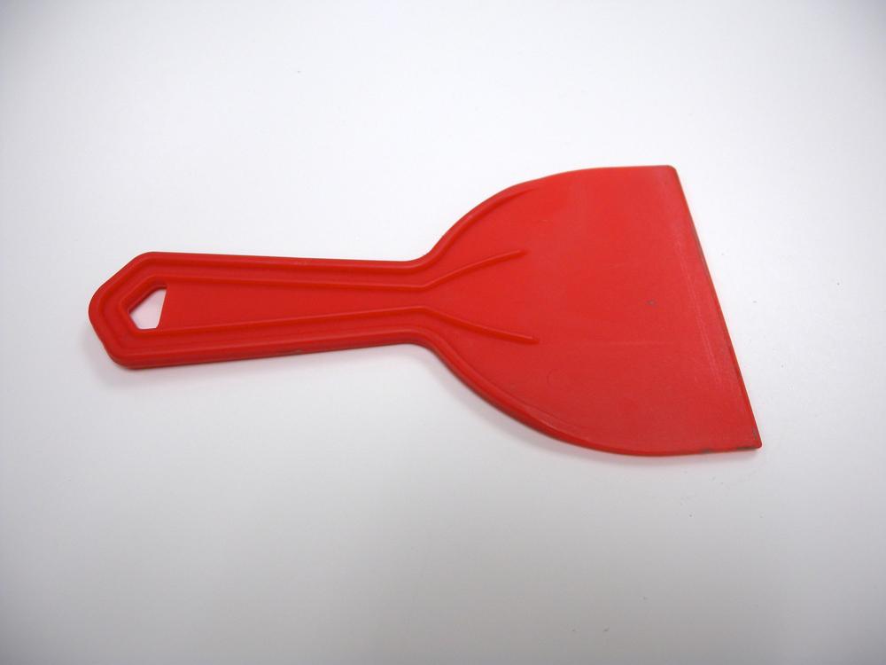
Squeegee |
Tweezers |
Reflow Soldering Process
This project requires that safety glasses be worn throughout its entirety.
- Step 1
- Start by compiling all of the tools and materials necessary for this project on the same table and within close proximity to one another (Figure 4-51). The solder paste has a relatively short time frame in which components can be held in place via the solder’s tack. As soon as the the volatiles evaporate, it is much harder to prevent the components from being bumped off of their respective pads. It is OK if you do not perfectly align the components prior to putting them in the oven because the surface tension of the molten solder will help to realign any mistakes.
- Step 2
- Secure the two rulers to the glass sheet perpendicular to each other by using a small amount of masking tape. Ensure that they meet at a 90-degree angle. Accuracy in this step is critical to guaranteeing the even distribution of solder paste over multiple boards. Evenly align a series of bare circuit boards on the glass sheet so that they are oriented in the same direction as your solder stencil. Gently place your solder stencil on top of the circuit boards so that the cutouts align with their respective pads. Once the stencil is aligned, tape only the top of the stencil to the glass sheet. This will allow you to apply paste to multiple panels of boards without having to realign the stencil. After everything is secure and the stencil is positioned, deposit a small bead of solder paste along the top of the stencil.
- Step 3
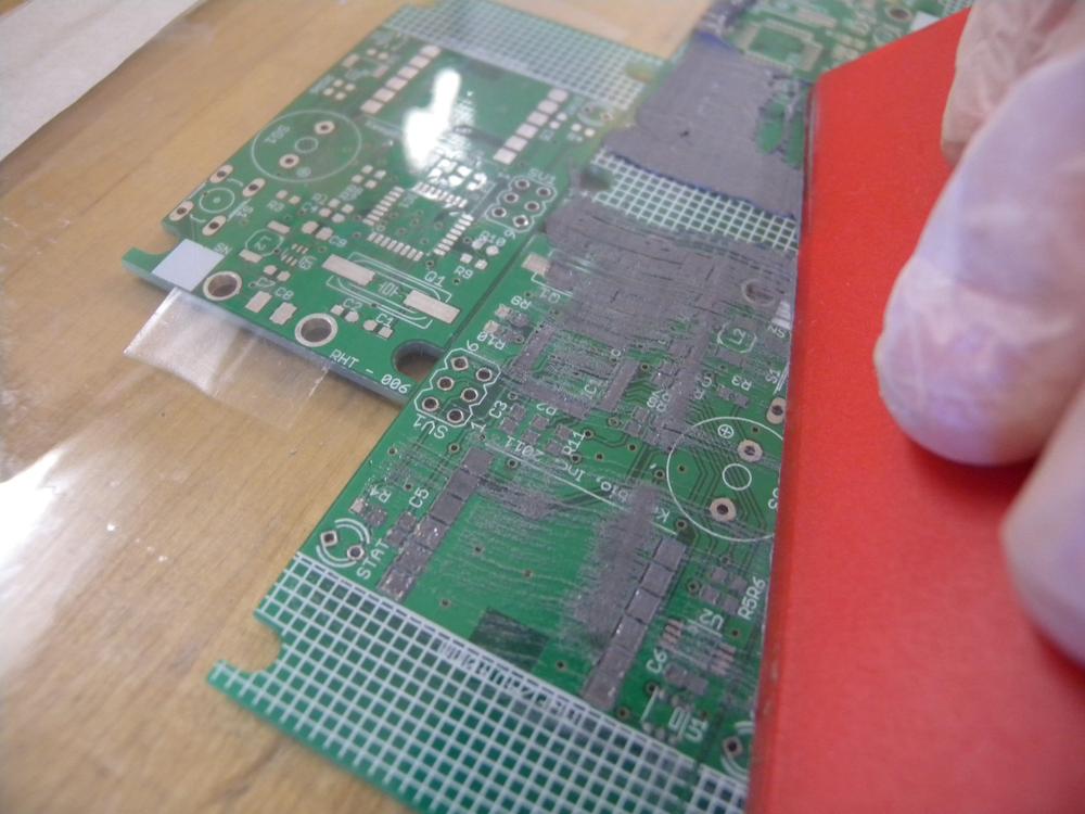
- Holding the bottom of the stencil with one hand and your squeegee in the other, wipe the solder down the stencil, applying even pressure and speed (Figure 4-52). The objective on the first wipe is to ensure that all of the cutouts have been filled with solder paste. Be careful not to shift the stencil during this process because it will result in improper deposition of solder onto the circuit board. If this occurs, scoop up the solder paste with your squeegee, wipe the boards and stencil clean with alcohol, and try again. Continue to hold the stencil in place and again pass the squeegee over the stencil. This removes any excess solder paste and ensures that every pad is evenly coated. If you shift the stencil during this process, you must wipe the boards clean and begin again.
- Step 4
- Carefully peel up the stencil in one smooth motion so as to expose the freshly prepped circuit boards. Remove the circuit boards from the fixture and place them on your work surface, being careful not to disturb the solder paste. Visually inspect each board for unwanted solder deposits or bridges. If you find one, use a tooth pick to correct the problem. The final product can have a little bleeding or overlap because it will be corrected during the heating process.
- Step 5
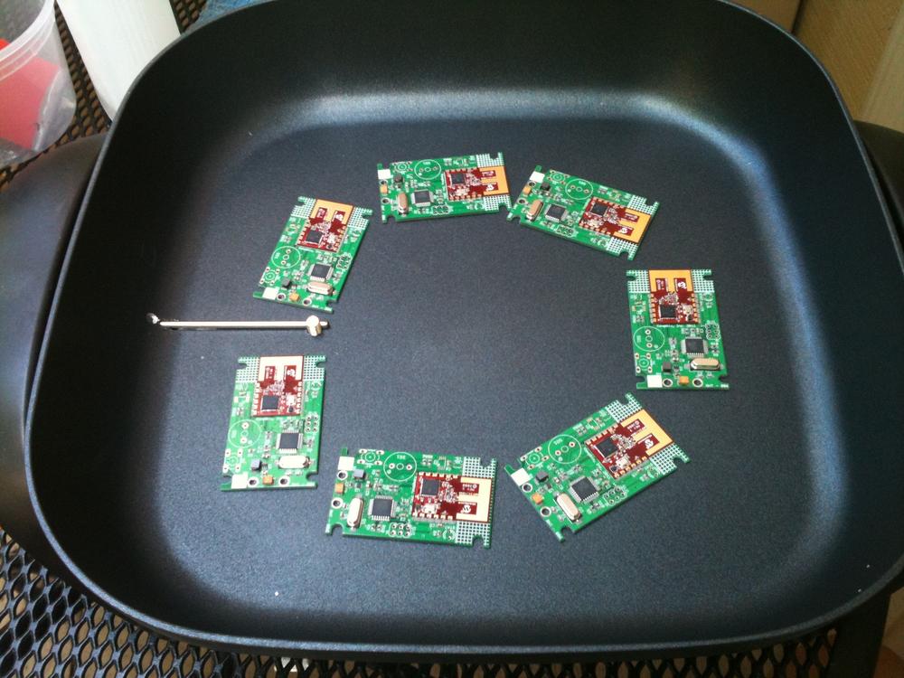
- Preheat your oven using the recommended profile and align each board so that they can be easily accessed (Figure 4-53). Populate the boards with the appropriate components, using tweezers or your fingers; just be careful not to smear the solder. Verify that components with position indicators such as diodes, polar capacitors, and integrated circuits are positioned properly. When the oven has reached the designated start temperature, carefully pick up and place your circuit boards onto the heated surface. Activate the solder profile and watch in amazement as the solder joints form before your eyes. If you are manually controlling your oven, use a timer for each stage of the profile. There is a short period of time during the reflow stage during which you can make minor adjustments to the components. Do this using the utmost care because the neighboring boards are very easily disturbed.
Project: Skillet Reflow
There are times when hand-soldering SMD components becomes too laborious or even impossible. It just so happens that a quick trip to the local home goods store can provide reflow equipment for under $100. The reflow process makes possible the simultaneous soldering of all of the components on a circuit board, and can even be done on both sides of a circuit board.
This project requires that safety glasses be worn throughout its entirety.
This project involves components that operate on household AC power. Never attempt to assemble or disassemble this project while they are plugged in.
Materials
| Materials List | ||
Item | Quantity | Source |
1/4-20 × 1 in bolt | 1 | Home improvement store |
1/4 in flat washer | 2 | Home improvement store |
1/4 in Nut | 1 | Home improvement store |
1200W Electric skillet | 1 | Home goods store |
22 gauge stranded sire | 1 | Electronics supply store |
6-32 × 1 in bolt | 2 | Home improvement store |
#6 washer | 2 | home improvement store |
6-32 nut | 2 | Home improvement store |
Adhesive cable tie bases | 6 | Electronics supply store |
Electronics enclosure | 1 | Electronics supply store |
Computer power cable | 1 | Computer supply store |
PID temperature controller | 1 | Electronics supply store |
PowerSwitch Tail II | 1 | Electronics supply store |
Thermocouple | 1 | Electronics supply store |
| Makerspace Tools and Equipment |
Wire stripper |
Screwdriver |
Drill with 1/4 in bit |
Safety glasses |
Rotary tool with cut-off wheel |
Cable ties |
Procedure
- Step 1
- Begin by determining the location of the components inside of the electronics enclosure. Mark the location of the PowerSwitch Tail’s mounting holes and the rectangular cutout for the PID as directed by your PID’s manual. An old rack-mount computer case is used in this example. Cut out the rectangle for the PID by using a rotary tool with a cut-off wheel.
- Step 2
- Unscrew the base of the electric skillet and mark a location for the temperature sensor 3/8 in away from one side of the heating element. Drill a 1/4 in hole at the location, taking care not to damage the heating element. Secure the temperature sensor in place with the bolt by sliding one washer over the threads, pass it through the hole, and then secure in place with another washer and the nut. Position the skillet onto the side of the enclosure and mark the mounting locations. Drill holes for each foot and attach the skillet to the side of the enclosure.
- Step 3
- Drill the PowerSwitch Tail’s mounting holes and secure in place with the 6-32 bolts followed by washers and nuts (Figure 4-54). Mount the PID in the cutout. Cut and strip two lengths of the stranded wire and connect them to the PID’s control output. Strip and connect the other ends of the wires to their respective locations on the PowerSwitch Tail. Verify the polarity. Connect the temperature sensor to the PID, also accounting for polarity.
- Step 4
- Ensure that the computer power cable is not plugged in and cut off the C13 connector. Strip off 2 in of the outer insulation and the ends of the three wires. Connect the wires to their designated locations noted in the PID manual. Pass the power cable out of the enclosure but do not plug it in!
- Step 5
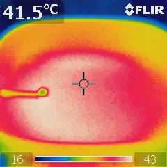
- Plug the electric skillet into the PowerSwitch Tail and set the temperature to MAX (Figure 4-55). Coil the remaining cable and secure with a tie. Secure any loose wires by using the cable tie mounts and ties and check for any loose wires. Close up the enclosure and plug in the PID. If everything is hooked up correctly, your PID should illuminate showing you about 20° C (or whatever your room temperature is). Configure your PID according to the manual and, when ready, plug in the PowerSwitch Tail. The controller should now power on and off the skillet as it reaches the desired temperature. Remember, only use this skillet in a well-ventilated area. The fumes released during reflow can be harmful, and every precaution should be taken to ensure the safety of you and those around you. Congratulations! You have just assembled a reflow skillet that will serve your Makerspace for years to come!
- Troubleshooting
- Disconnect the power from the source and ensure that the leads have been appropriately connected to the PID.
If the PID turns on, but the skillet does not heat up:
- Verify that the temperature knob on the skillet is set to its highest point.
- Ensure that the PID is properly connected to the PowerSwitch Tail.
If the skillet heats up, but the solder never melts:
- Some skillets are designed not to reach 500° F due to thermal degradation of the skillet’s coating. Purchase a different skillet and do not exceed the skillet’s maximum temperature, because you run the risk of damaging your components as well as releasing toxins from the skillet’s non-stick coating.
Desoldering and Rework
It’s going to happen: you just discovered that you reversed the polarity on a capacitor or your surface-mount integrated circuit was installed backward; bummer man! Rework or desolder that sucker and get your project up and running. Rework is a great skill to learn and can save you save a lot of money in components by scavenging them from unused circuitry.
Reworking and desoldering are the skills that, when mastered, will allow you to better troubleshoot and repair errors on current projects as well as salvage components from existing boards, ultimately saving you time and money. The following section provides descriptions and methods for using some of the common tools employed when reworking and desoldering.
Desoldering Tools
- Desoldering Braid
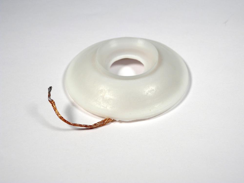
- Desoldering braid comes as a spool of tightly woven copper strands impregnated with a small amount of flux (Figure 4-56). This braid is used in conjunction with a soldering iron to remove solder through capillary action and the copper’s natural wettability. You use desoldering braid by first placing the braid on top of a solder joint and gently applying the soldering iron. The iron then heats both the braid and the solder until the solder is wicked away from the circuit board. This tool is useful for cleaning pads after components have been removed, and although you can use it to remove through-hole components, it is often difficult and can result in damage to the circuit board due to overheating.
Apply a small amount of solder to the braid prior to desoldering. This helps accelerate the heating process and therefore reduces the amount of time in contact with the joint.
- Solder Sucker
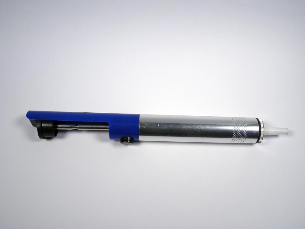
- A solder sucker or vacuum is a syringe-like device that uses a button activated piston to suck away molten solder (Figure 4-57). You use this tool by first heating the solder joint with a soldering iron until the solder is completely molten, and then quickly covering the joint with the tip of the solder sucker and pressing the button. Most of the solder will be sucked into the body of the tool and can be removed when necessary. The solder sucker is primarily used for removing solder from through-hole solder joints because it is capable of removing a large quantity of solder quickly.
- Specialty Solder
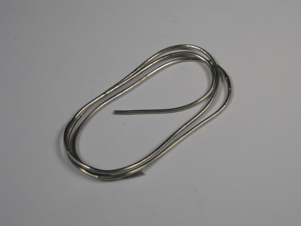
- There are solder alloys specially designed for the desoldering and rework process (Figure 4-58). These alloys have a much lower melting temperature than standard solder and you mainly use them for the safe removal of SMD components. Working in conjunction with a flux formulated for this process, solder is applied with a soldering iron to all of the pins that secure the component in place. When every pin is covered, you can lift the component with tweezers or a suction cup. If you do this quickly enough, all of the solder can be removed by giving the component one gentle tap on your work surface. Alternatively, you can remove the solder by laying one row of pins along a piece of de-soldering braid, which wicks it away with a quick pass of the soldering iron.
Project: Inexpensive Hot-Air Desoldering/Rework Tool
There’s not much that’s more frustrating than installing a component backward. Especially if it is a fine-pitch device with a lot of pins. The easiest way to remove or replace a damaged or incorrectly installed component is with hot air. Although this method is a lot less invasive than using a soldering iron, it requires expensive equipment to complete. This project is designed to show you how to convert an inexpensive bulb-type desoldering iron into a hot-air gun for de-soldering and rework.
This project requires that safety glasses be worn throughout its entirety.
This project involves tools that operate at exceedingly high temperatures. Use the utmost care when working with these tools and never rest the iron on a flammable surface.
Materials
| Project Materials List | ||
Material | Qty | Source |
1 in hose clamp | 1 | Home improvement store |
1/8 in × 36 in silicon tubing | 1 | Hobby store |
45 W desoldering iron with bulb | 1 | Electronics supply store |
Diaphragm-type aquarium air pump | 1 | Fish supply store |
Small piece of brass wool | 1 | Electronics supply store |
| Project Tools List |
9 mm socket or open-ended wrench |
Scissors |
Procedure
- Step 1
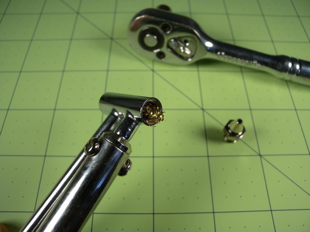
- Start by using the 9 mm wrench and carefully remove the soldering iron’s tip (Figure 4-59). This exposes a small section of inner chamber. Using the pair of scissors, cut off approximately 1/4 in × 1/4 in of the brass wool and insert it into the exposed chamber. This wool increases the surface area of the heater and will therefore increase the output temperature. Carefully re-attach the tip with the wrench and remove the rubber bulb from the back of the air tube.
- Step 2
- Slide approximately 1/2 in of the tubing over the end of the air tube. Carefully open the 1 in hose clamp and slide over the iron’s handle and air tube. Rewind the hose clamp so that the screw mechanism is positioned on top of the tube. You can use this clamp to adjust the airflow by gently loosening and tightening the screw.
- Step 3
- Finally, attach the free end of the aquarium tubing to the air pump and the project is complete! Congratulations! You have successfully constructed a hot-air desoldering and rework tool for under $20!
- Troubleshooting
If the iron does not heat up:
- Make sure it is plugged in.
If the iron does not blow hot air:
- Check the air hose connection from the pump to the air tube for kinks, or that your hose clamp is tightened too tightly.
- Check that the brass wool is not constricting the airflow.
If the hot air is not hot enough to melt the solder:
- Check for airflow problems. Sometimes, if the airflow is too high, it doesn’t have time to heat up. Alternatively, if the airflow is too low, not enough hot air is produced to heat the solder joint.
- Move the tip closer to your project.
- On stubborn parts, you can preheat the board with a hair dryer or heat gun.

