Chapter 7. 3D Design and the 3D Printer
The availability of 3D printing in Makerspaces has exploded since the first RepRap Darwin was produced in 2007. This is the new wagon headed west. Inspired by its success, the open source community has engineered numerous versions and has made this technology more than affordable for any Makerspace. The 3D printer deposits material layer by layer until the desired computer-generated model is produced. With its almost limitless potential to produce usable objects, it’s not hard to see why the 3D printer has become so popular.
Today, there is a wide spectrum of commercially available 3D printers, including the Cube, the MakerBot lineup, Ultimaker, Up, and the list goes on. All of these machines provide a ready-to-go system with which you can create physical objects from virtual models. This chapter aims to dissect the components that make these technologies work and provide you with a better understanding of the ins and outs of 3D printing.
For more information about choosing a commercial 3D printer, check out the Make: Ultimate Guide to 3D Printing (http://makezine.com/volume/make-ultimate-guide-to-3d-printing/), which provides a comprehensive list of reviews. Also, take advantage of the extensive wealth of information on the RepRap Wiki (http://reprap.org)
3D printers have four main requirements: a computer, power, ventilation, and storage. Each 3D printer operates via continued communication with a host computer or attached flash storage. Regardless of the method for delivering the solid model to the 3D printer, there is frequently a computer within close proximity to the printer. Because this computer and 3D printer require an electrical connection and often need to be powered for an extended period of time, a dedicated connection is necessary. Finally, the 3D printer workstation should have access to either active or passive ventilation. This could come in the form of positioning it next to a window or through the use of a local ventilation system. Finally, adequate storage should be available for all of the feedstock and tools required to operate the machine.
Facilitating Design Using 3D Computer-Assisted Design Software
Elevating sketches from two-dimensional profiles to three-dimensional extrusions opens up a world of fabrication possibilities. The parts created within 3D Computer-Assisted Design Software (CAD) provide full-scale virtual representations of your designs and make it possible for you to create prototypes, perform fit-checks, and make tweaks without raising a hammer. Using CAD also reduces the amount of time spent working with physical manufacturing because you can catch potential design flaws by piecing multiple parts together within an assembly. Depending on your software, these assemblies can even reflect motion, interference issues, and help to give a greater understanding of component interaction.
3D CAD utilizes many of the same design tools that are found with 2D, but allows for manipulation in the third dimension. When completed, these three-dimensional parts can be exported as solid-model design files compatible with most of today’s manufacturing technology, especially the 3D printer. Although 3D CAD entails a bit of a learning curve, practice makes perfect, and your designs will fly together quicker than you might imagine. Depending on your Makerspace’s software style preferences, there are a slew of free and open-source applications that are currently available, with several of them listed in Table 7-1.
| Software Title | Developer | Platform | Link |
AutoDesk | OS X, Web App, Windows | ||
Blender development team | Linux, OS X, Windows | ||
FreeCAD development team | Linux, OS X, Windows | ||
AutoDesk | OS X, WebGL, Windows |
The 3D Environment
If you treat 3D CAD as an extension of your reality, designing in this environment really makes sense. Objects have size, orientation, masses, and features, just as they would in reality, and because so much realism can be integrated within these designs, they can provide a seamless transition into reality. Imagine building with clay on your workbench. The physical orientation of the part and its design features always correspond to a constant plane. This plane, or work plane, becomes the platform on which your design is created.
Working with 3D CAD begins with an understanding of the work environment. This includes the base configuration of the software, the different design types, and all of the tools available for designing and creating. With a little patience and a lot of imagination, you will begin to see the amazing potential three-dimensional design has for the production of parts within your Makerspace.
As with any CAD software, design is based around objects drawn within a specified unit system. This option happens to be the first to pop up during new software installation and can generally be found by clicking Tools→Options. Many of today’s 3D printers use millimeters as their default unit; you need to take note of the system in which you are drawing. Don’t worry if you begin drawing in one system because both your CAD software and the 3D printers control software offer the ability to scale the part to the desired size.
3D CAD utilizes two different types of files: parts and assemblies. Parts are individual objects, and assemblies are complex objects made out of the individual parts. For example, let’s consider designing a filament extruder. This mechanism is made out of a series of individually designed parts that can then be virtually combined into an assembly. These assemblies are then used to simulate the interactions of all of the parts and greatly assist with isolating design problems prior to physical construction.
Upon the creation of a new part file, you will be presented with your workspace. The typical workspace is divided into three work planes that define the primary starting points for most sketches. Consider a box sitting on a table. If you look down on the box, you will be looking down on the top work plane. Looking at the front of the box, you see the front work plane, and looking at the right side of the box you see the right work plane. These three work planes are derived from conventional drafting techniques that define a part using the top, right, and front views.
As your part evolves, each surface and the space around the initial three planes can become a new work plane. This makes it possible for you to create components relative to surfaces other than the three primary planes. There are two ways to achieve these secondary work planes. The first is to select a surface and create a new sketch on that surface. Depending on the CAD suite used, this new sketch inherits dependencies for that reference. This means that if the referenced surface changes, the sketch will change, as well. Although these dependencies can be removed, they make alterations and updates considerably easier because you only have to alter one element and all of the elements with dependencies change along with it. The second method is to insert a new work plane relative to one of the primary planes. Using this method, you can create planes that are offset parallel or at a specific angle relative to that primary plane. This method is exceedingly useful if you are aware of the dimensions of the part you are creating.
3D Design Starts with 2D
Nearly every three-dimensional drawing starts with a two-dimensional sketch. The sketch is the “cookie cutter” that defines the design characteristics of what you will extrude into 3D space. Create a new sketch by selecting the work plane of choice; you will be presented with a series of design tools that are identical to those found in 2D CAD. Create the profile that defines your part, and you are ready to extrude.
However, there are few details that need to be addressed prior to extruding a solid model:
- The profile of your part needs to be fully connected. If you think of this profile as the walls of a cup, if there were holes in the wall, the contents would pour out. For the CAD software to see this as a “fully defined” profile, it needs to be fully connected.
- You can have design features internal to this profile, such as circles. These features need to be fully defined and will result in a hole being created in your part. This is a useful trick to implement if you know the position of holes prior to the design of your part, and saves the need for creating a new sketch later on.
- Don’t fillet or chamfer the edges of your design until after you extrude the profile. When you enter 3D mode, you will be able to add the fillets and chamfers you want, and it’s easier to modify them than to do so in 2D.
After your design is complete and error free, it’s time to move into 3D space. This is accomplished by using a series of three-dimensional design tools with which you can extrude, rotate, loft, and sweep your profile as needed. After you have extruded your initial sketch to the desired height, every surface of your new part can become a work plane. This is how you can design complex parts that are not constrained by the initial three work planes. Select the surface you would like to draw on and select the New Sketch tool to create a new sketch on that surface.
3D Drawing Tools
Drawing in 3D is a lot like pottery class: models are shaped, molded, and extruded into virtual volumetric forms that can be physically created using devices like the 3D printer. Consider the way a clay is pushed through a mold. You start out with the profile of the mold and extrude the material until the desired length is achieved. This new structure can then be manipulated into the desired form by using tools that both add and subtract material.
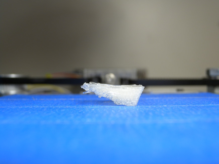
When designing parts for output on a 3D printer, there are a few design tricks you can use to greatly improve the quality of the end product. Most 3D printers cannot print overhangs greater than 45 degrees. This restriction is a direct result of the method in which the printer creates objects by overlapping the extruded filament. If there isn’t anything under the filament when extruded, it will sag, creating a spaghetti-like mess (Figure 7-1).
There are two methods for tackling this problem. First, use support material. This setting tells the G-Code Generator (see Computer-Aided Manufacturing and G-Code Generation) to add small amounts of structure to overhangs. This material can be removed after the print is complete. The second method is to use clever design. When printing objects, like circles that have necessary overhang, modify their design to include an angled cap that does not violate the 45 degree rule.
Alternatively, you can split your model into multiple parts. The overhang constraint imposed by the 3D printer limits objects with top and bottom components. If the model has required components that violate the printer’s design constraints, break the model into multiple pieces and assemble it with fasteners to achieve the complex shape.
The following tools are used by most 3D CAD software in the creation of solid models. These tools are designed to create and manipulate models in three-dimensional space, and with a good understanding of their fundamentals, anything is possible.
- Chamfer
- You use the chamfer tool to bevel the edge of a part. It works on both convex and concave edges. You can use this tool to provide a symmetrical or asymmetrical bevel to the edge whose lengths and angles can be defined. Not only do chamfers improve the appearance of parts, they are also used to improve the strength of joints by more evenly distributing forces between two faces.
- Extrusion
- You use the extrude tool to pull design profiles into three-dimensional space. This is the primary tool used for the initial creation of solid models. Upon selecting the tool, you are prompted to enter a series of parameters that define the extrusion. The first of these is to select the desired profile. As mentioned before, the profile must be complete and without extraneous elements, like floating line segments. The next parameter to define is the direction and length of the extrusion. This feature dictates just how long your extrusion will be and in what direction relative to the work plane.
- Extrude Cut
- The extrude cut tool is identical to the extrude, except it removes material rather than adding it. Upon selecting the tool, you are prompted with the same parameters as those for the extrude tool, except the extrusion must be made in the direction that is internal to an existing part. Imagine this tool as a cookie cutter; you select the shape of your cutout, direct it toward your part, and set the depth of the cut. This tool provides a great way for removing material from a part and creating design features such as channels and holes.
- Fillet
- You use the fillet tool to make a rounded edge of a part with a specific radius. It works on both convex and concave edges. Not only do fillets improve the appearance of parts, but they are also used to improve the strength of joints by more evenly distributing forces between two faces.
- Loft
- The loft is used to produce a software-defined connection between two profiles. This connection can either hollow-out an object or make it solid, making complex contours possible. A good example is in the design of a boat hull. The contour can be created by producing a series of profiles that define the primary hull characteristics. Then, a loft can be created from the bow to the stern, filling in the space between the profiles.
- Measurement
- Measurements and dimensions are utilized both in 2D and 3D design. After the part has been created, you can use the measurement tool to establish the distance between two parts or elements. This tool is handy for verifying the dimensions of your design prior to manufacturing. You can also use it to alter the existing dimensions if the part is properly constrained.
- Patterns
- You use the pattern tool to create multiple copies of a pre-existing component or body. When you have completed the desired design element, use this tool to select the design element to make copies. This tool can create a linear array or radial pattern and is considerably helpful when designing a part with multiple identical elements, such as spokes for a wheel or the teeth of a gear.
- Revolve
- You use the revolve tool to rotate a profile around a central axis to any desired degree. Design with this tool is used by creating two design features, the profile and the axis of revolution. Create a new sketch on the desired work plane, draw the profile, and make sure it is complete. Create a new sketch on the same work plane at the location where you want your profile to be revolved and draw a short line. The length is arbitrary: it’s only used as a reference. When complete, select the revolve tool and you will be prompted to select a profile and an axis for revolution. Next, set the degrees of revolution, use 360° for a complete revolve.
- Revolve Cut
- This revolve cut tool is identical to the extrude tool and similar in function to the extrude cut. Follow the same method for creating the profile and axis of revolution used with the revolve tool, except ensure that the profile will be swept through a previously existing model. This tool is handy for creating complex cutouts that follow an arc through a part, such as creating a cavity within a block when designing a mold.
- Sweep
- The sweep tool provides similar functionality as the loft tool, except the contour of the sweep does not change along its path. To use this tool, you first create a profile and then a path that extends perpendicularly to the surface of the profile. The sweep tool then extrudes the profile along the defined path. You can use it to create a hollow or solid object. Sweeps are often used to represent wire paths through a machine in an assembly or when defining a part’s complex bends.
Project: 123D Design for 3D Design
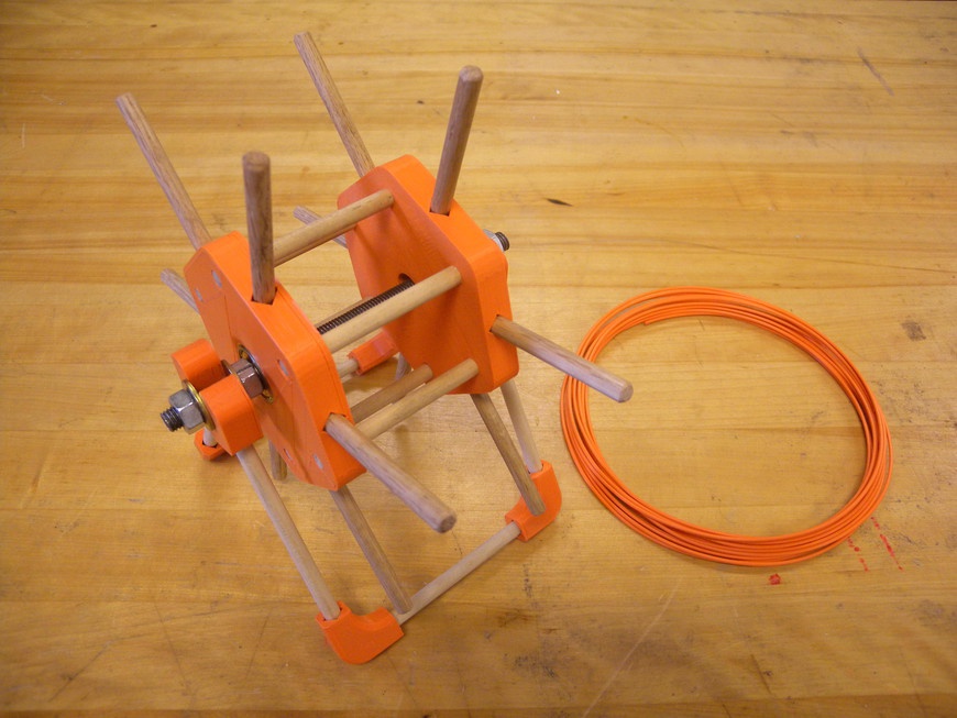
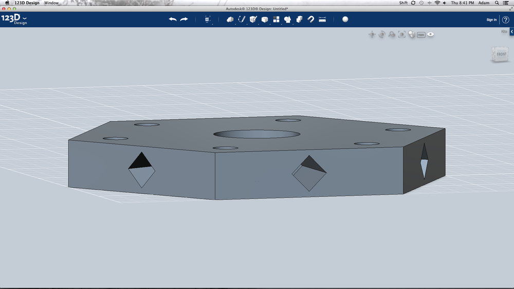
A commonly overlooked accessory for a 3D printer is a holder for the filament spool. This filament is often awkwardly propped against the machine, placed on the floor, or even hung from the ceiling. Consequently, the result is a tangled mess that requires constant attention. This project is designed to provide a quick introduction to the world of 3D modeling through the use of Autodesk’s free 123D Design software to design a simple filament holder (Figure 7-2) for your Makerspace’s printer.
The software provides the basic tools necessary to produce and edit solid models. When you start it, you are greeted with an empty workspace and a default unit system set to millimeters. Across the top of the window are the editing tools followed by the viewport selection widget. One of the perks of using 123D Design is its user-supported online database of models that you can import through the parts library. When parts are saved, you have the option to save them locally or upload them directly to your account with Autodesk. From there, you can make your drawings public and share them with the world.
Because 123D Design does not feature a visible design feature history or design tree like that found in Inventor and Solidworks, it is important to frequently save multiple revisions of your work. This will allow you to go back in time and make the necessary adjustments rather than overwhelming the undo button.
Materials
You can find the files for this project at Thingiverse.com.
| Materials List | ||
Item | Quantity | Source |
1/4 in × 36 in hardwood dowel | 3 | Home improvement store |
8 mm × 22 mm ball bearings | 2 | Sporting goods store |
M8-1.25 × 150 mm threaded rod | 1 | Home improvement store |
M8-1.25 nut | 2 | Home improvement store |
M8 washer | 4 | Home improvement store |
| Makerspace Tools and Equipment |
3D Printer |
Band saw |
Sandpaper |
Epoxy |
Computer with CAD |
Designing the Spool Structure
- Step 1
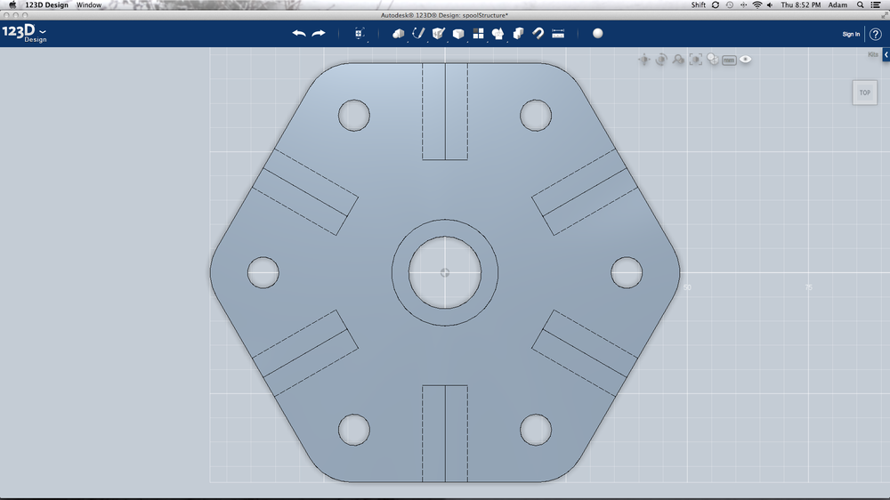
- Begin by selecting the Top viewport by clicking the top of the viewport widget. This reorients your screen so that you are looking down on the initial sketch plane. Highlight the Sketch toolbox and select the Polygon tool. You will use this tool to produce the primary structure of the spool (Figure 7-3). After selecting the polygon tool, click the sketch plane and place the center point at the plane’s origin. Move your cursor to the right until the measurement reads 25 mm and set the number of sides to 6. Click to complete the drawing. Alternatively, you can enter 25 mm into the measurement box and press enter. Press Esc to exit the tool and save your work.
- Step 2
- Select the area within the polygon and then, from the Sketch toolbox, select the Circle tool. Move the mouse to the origin of the polygon and create a circle with a 15 mm diameter. Again, select the area within the polygon and then, again from the Sketch toolbox, select the Polyline tool. Create an 8 mm long line segment that extends from one point of the polygon inward at 30 degrees relative to the origin and then exit the tool. Select the area within the polygon and create a 6.5 mm wide circle at the end of the line segment and then exit the tool. Select and delete the line segment. The polygon and circles you just created will act as a “cookie cutter” that defines how the object will be extruded. Press Esc to exit the tool and then highlight the area outside of the center circle. This defines the area that is to be extruded by using the Extrude tool. From the Construct toolbox, select the Extrude tool and extrude the polygon shape upward 12 mm. Exit the tool and save your work.
- Step 3
- Create an array of holes by changing your view to the Home position and then, from the Pattern toolbox, select the Circular Pattern tool. Select the visible wall of the 6.5 mm-wide hole to set the faces to pattern. Change the selection mode to Axis by clicking the Circular Pattern tool’s axis selection cursor. Select the visible wall of the center circle, change the pattern count to 6, and then press Enter. This should create a pattern of 6 holes around the center circle. Save your work.
- Step 4
- Change the view back to Top, select the area around the top of the extruded shape, and then select the Circle tool. Selecting the area prior to selecting the tool informs 123D on which plane you want to draw and makes the drawing process less confusing. Create a 22 mm circle at the origin of the polygon and exit the tool. Select the area inside the circle and then select the Extrude tool. Rather than extrude new material, you will be removing material from the body of the extruded polygon. Set the dimension of the extrude to –10 mm, click the drop-down menu next to the measurement text box, and then change the extrude type to Cut. Press Enter and the 22 mm circle should have cut a 10 mm-deep hole extracted from the extruded polygon. Exit the tool and save your work.
- Step 5
- Change your view to Front and select the Rectangle tool. Upon selecting the tool, a dialog box opens next to your cursor asking you to select a sketch plane. Select the side of the extruded polygon facing you and then, with the “Sketch” toolbox, select the Rectangle tool. Create a 6.5 × 6.5 mm square located at the new origin and exit the tool. Select the area inside the square and then move your cursor over the Settings icon (the gear-shaped graphic). Select the Move function and click the arrow that represents the X-axis. Move the square along the X-axis 3.25 mm and the Y-axis 2.75 mm so that it is centered on the side. Again, use the Move function to rotate the square by dragging the rotation handle and setting the angle 45 degrees. Exit the tool and change your view back to the Home position. Select the area within the circle and make an extrude cut 15 mm into the body of the shape. Use the Circular Pattern tool to pattern the extrude cut 6 times around the object (Figure 7-4). You might have to select all five sides of the rectangular cutout for the operation to complete. Exit the tool and save your work.
- Step 6
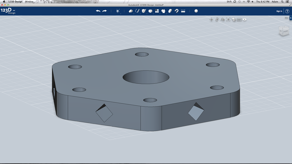
- From the Modify toolbox, select the Fillet tool and select each vertical edge of the polygon extrusion. Set the fillet radius to 10 mm and press Enter. This rounds the edges of the polygon and speeds up the build process by removing unnecessary material (Figure 7-5). Save your work, open the 123D Design menu, and then click Export to save the drawing as a 3D printer-compatible .stl file. The part is now ready for printing. Open the part in your 3D printer’s control software and print away!
Designing the Spool Mount
- Step 1
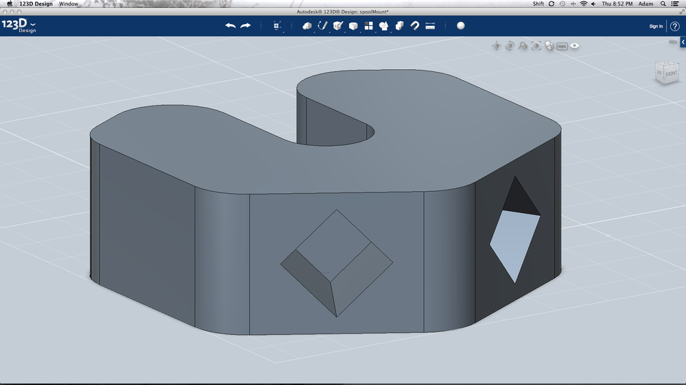
- Now, it’s time to work on the mount (Figure 7-6). Start by creating a 20 mm hexagon located at the origin by using the Polygon tool. Select the area inside the polygon and draw an 8 mm diameter circle. Using the Polyline tool, draw a line starting at the origin of the 8 mm circle and connect it to the edge of the circle along the x-axis so that it snaps to the grid. Continue the polyline upward until it snaps to the edge of the polygon. The resulting line should be 17.691 mm long. Repeat this process for the other side of the circle and then exit the tool. This makes a channel that facilitates loading of the spool into the holder. Select the area within the polygon and then, from the Sketch toolbox, select the Trim tool. Remove the unnecessary lines by clicking them when they turn red. Extrude the resulting shape 12 mm and save your work.
- Step 2
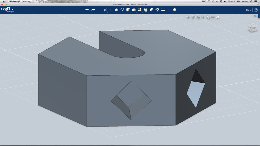
Change your view to the Home position and create a 6.5 × 6.5 mm square on the lower-left side of the polygon shape. Use the Move tool to move the square to the center of the side and rotate it 45 degrees. Extrude cut the square 10 mm into the body of the shape. Use the Circular Pattern tool to copy the extrude cut to the opposite side. You can do this by selecting 5 surfaces of the extrude cut, setting the number of instances to 2, and defining the 8 mm hole as the axis. Change the pattern type to Angle and change the angle to 60 degrees by dragging the indicator arrow until the angle dialog box opens. Exit the tool and save your work.
Using the Array tool, you can repeat an element in a linear pattern or around an axis (Figure 7-7). Make sure you select every element of the feature you want to pattern before finishing the tool.
- Step 3
- Select the Fillet tool and fillet the vertical edges of the polygon with a 5 mm radius. When complete, save your work, export the file as an .STL, and print away!
Designing the Spool Feet
- Step 1
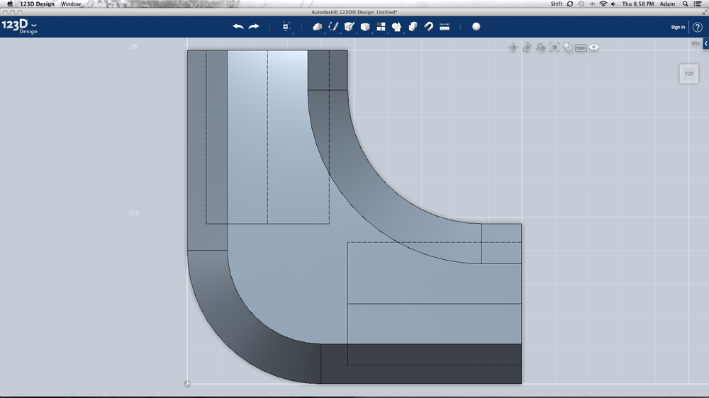
- The final step in this project is to design the spool holder’s feet (Figure 7-8). Begin by creating two 12 × 25 mm rectangles located at the origin and perpendicular to each other. Extrude the shape up 12 mm. Create a 6.5 × 6.5 mm square located at the center of the end of one side, rotate it 45 degrees, and then extrude cut it 13 mm into the shape. Repeat this process for the remaining side and then save your work.
- Step 2
- Select the Fillet tool and fillet the vertical edge at the origin and the crux of the shape with a 10 mm radius. From the “Modify” toolbox, select the Chamfer tool and apply a 3 mm chamfer to the top and bottom edges. When complete, save your work, export the file as an .STL, and print away!
Making the Filament Spool and Holder
- Step 1
- To construct the filament holder, start by cutting all 15 × 4 in, 4 × 9 in and 2 × 6 in pieces of the 1/4 in dowel by using the band saw. Gently sand the edges of the cut dowels to prevent splinters and to assist with insertion into the plastic parts. Assemble the spool by mixing up a small quantity of epoxy and gluing 5 × 4 in dowels between the spool holders. Ensure that the bearing mounts are facing out. When these are dry, glue the remaining 10 × 4 in dowels onto the ends of the holder. Push one bearing into each bearing holder (Figure 7-9).
- Step 2
- Assemble the spool mount by mixing up another batch of epoxy and gluing the 4 × 9 in dowels into the spool mounts. Glue one foot to the end of each 9 in dowel and connect together using the 2 × 6 in dowels.
- Step 3
- Slide the M8 threaded rod through the two bearings and lightly secure in place with a nut on each side of the spool. Place a washer over each end of the threaded rod and place the spool onto the holder. Add another washer to each end and secure in place with a nut. The spool should now spin freely and is ready for use.
CNC Fundamentals
Computer controlled machines have been around since the mid-1900s and were designed to replace the human operator, providing greater consistency and the ability to work without break. The concept of Computer Numerical Control, or CNC, has made its way into the Makerspace environment in the form of CNC mills, lathes, and most recently, the laser cutter and 3D printer.
The CNC process starts with a two- or three-dimensional drawing made in CAD. This drawing is then sent to a processor, or G-Code Generator, where it is deconstructed into a series of machine movements based on the size of the tool and capability of the machine. The resulting code, or G-Code, is then systematically fed into the CNC control system, which interprets each line of code and moves the axis and tools accordingly. It really is a fantastic process to witness and with a little understanding of each step of this process, your Makerspace will be better equipped to operate and maintain its most sophisticated equipment.
CNC Hardware
CNC machines are identical to their hand-driven counterparts but utilize indexable motors in lieu of hand wheels. Machines such as the 3D printer have three axes, which enables the movement of the extruder to any position in its three dimensional build area. These machines can be set up in three configurations to achieve three-dimensional movement.
- 3D Printer Axis Configuration
Configuration 1
- Extruder moves on x- and y-axis
- Build platform on x-axis
Configuration 2
- Extruder moves on x- and y-axis
- Build platform moves on y-axis
Configuration 3
- Extruder moves on z-axis
- Build platform moves on x- and y-axis
Each axis consists of a motor (whether it be a stepper or servo) that is directly connected to a drive mechanism. This drive mechanism translates the rotation of the motor into the linear motion required by the axis. As the motor turns the drive mechanism, the axis carriage is moved to the specified linear position. The position of the carriage is determined by using endstop devices that detect the minimum or maximum linear position.
Stepper Motors
The stepper motor is a brushless electric motor that produces controlled output rotation from a series of electromagnetic pulses. Contrary to a brushed DC electric motor, which produces continuous rotation when connected to a power source, the stepper motor requires a driver circuit that controls the position of the rotor as it rotates.
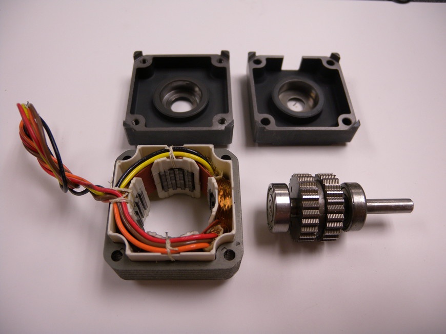
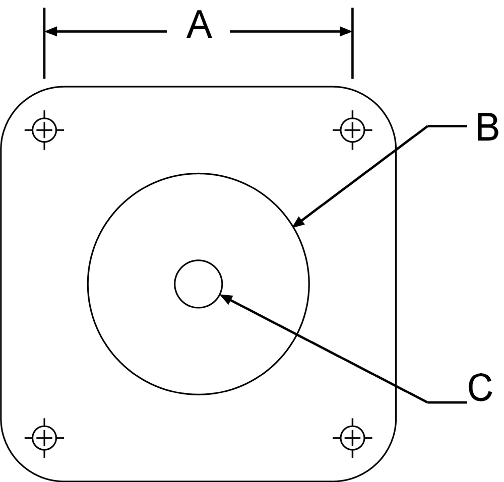
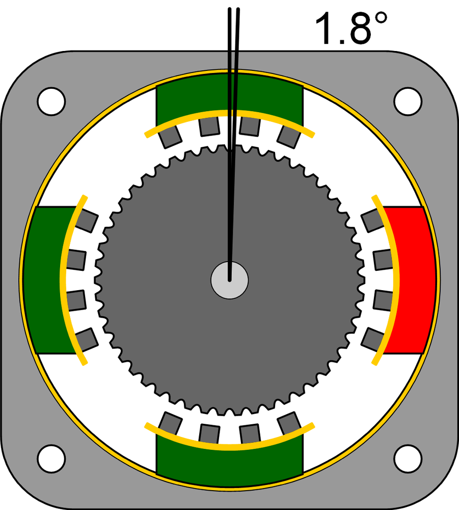
Each motor is made up of a multiphased stator containing a series of toothed coils and a multi-toothed rotor (Figure 7-10). Motion occurs when the controller sends a pulse to one of the coils, which aligns the poles of the coil to that of the rotor. The typical stepper motor requires 200 steps to complete a rotation, which works out to 1.8 degrees of rotation per step. Because a stepper motor can only execute one step at a time and each step is at the same angle, feedback is not required, resulting in relatively simple drive system. The dimensions of each motor are standardized by the National Electrical Manufacturers Association (NEMA), and are illustrated in Figure 7-11. Table 7-2 lists the standard dimensions.
| Frame Size | A (mm/in) | B (mm/in) | C (mm/in) |
8 | 16.0/0.630 | 15.0/0.591 | 4.0/0.157 |
11 | 23.0/0.906 | 22.0/0.866 | 5.0/0.197 |
14 | 26.0/1.024 | 22.0/0.866 | 5.0/0.197 |
17 | 31.0/1.220 | 22.0/0.866 | 5.0/0.197 |
23 | 47.14/1.856 | 38.1/1.50 | 6.35/0.250 |
34 | 69.6/2.74 | 73.02/2.875 | 12.7/0.5 |
The power output of a stepper motor is based on how much torque and speed the motor can produce. Typically, manufacturers present a motor’s voltage, current consumption, holding torque, and steps per rotation on a label located on the side of the motor or within the motor’s specification sheet. In general, the more power the motor consumes, the stronger it will be. Although more power sounds good at first, it might not be necessary. Choose a motor that is best for the task by determining what kind of drive system it will be turning and what kind of load it will be moving. The motors needed to move the x- and y-axis of a 3D printer don’t necessarily need to be the same size as the z-axis motor. Making informed decisions about the type of stepper motor you should use in your project will lead to better performance, less strain on the control system, and lower component costs.
The most common types of stepper motors are 6-lead unipolar and 4-lead bipolar. Unipolar stepper motors contain a center “tap” that bisects each coil so that the motor can be driven without changing the coil’s polarity. Bipolar stepper motors contain a single coil per phase and require the controller to reverse the polarity on the coil in order to change direction.
You can use unipolar stepper motors as bipolar by attaching the ends of each coil to the bipolar driver and disregarding each coil’s tap.
The color coding (Tables 7-3 and 7-4) for stepper motors can vary from manufacturer to manufacturer and can be easily determined just by using a multimeter. Configure your multimeter to measure <10 Ohm resistance and create a list of wire colors. Connect the multimeter’s leads to any two wires, note the resistance, and continue for all combinations. When you have located pairs of wires with the least resistance, you have found a coil.
Drive Mechanisms
Linear drive mechanisms are designed to translate the rotational motion of the motor to the linear motion of the carriage. This is accomplished by directly coupling the motor to the carriage using one of the following methods.
- Motor Coupling
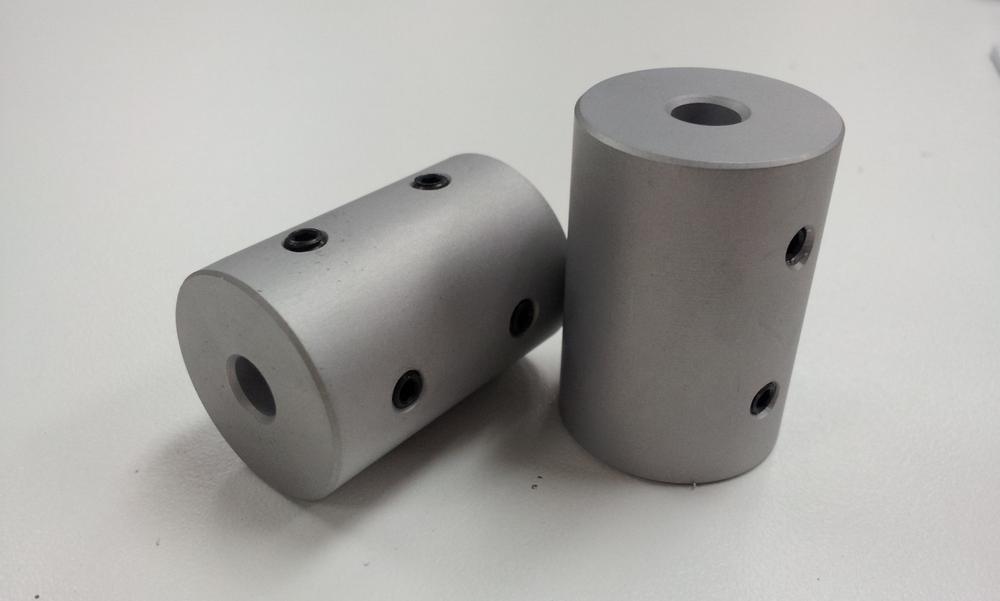
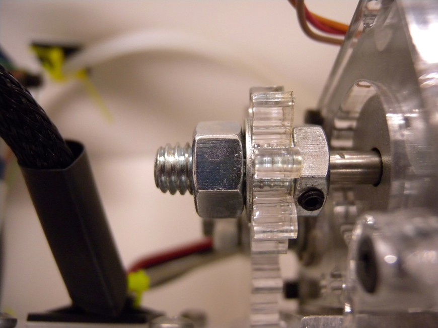
- The most important aspect in the linear drive mechanism is the method in which the motor is coupled to the system (Figure 7-12). This is accomplished by attaching a pulley or coupler directly to the shaft and securing in place with a set screw. Methods that employ a piece of flexible tubing to couple the motor to the drive should be avoided because they produce a considerable amount of backlash or unintended rotation.
You can make a simple shaft coupler (Figure 7-13) out of a bolt that is a few sizes larger than the shaft diameter. Using a drill press or lathe, bore the center of the bolt to the diameter of the motor’s shaft. When this is complete, drill and tap a hole in the head of the bolt for the set screw.
- Screw
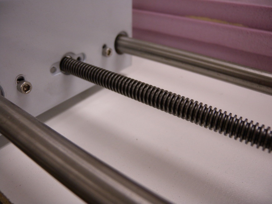
- Screw-drive mechanisms are predominantly used with CNC machines that require a considerable amount of linear stability (Figure 7-14). The mechanism consists of a threaded rod that interfaces with a threaded coupling on the carriages for the axis. When the threaded rod rotates, the coupling is moved along the direction of the threads. This drive method is commonly used for 3D printer’s z-axis because less strain is placed on the axis motor when the axis is not in motion.
- Belt
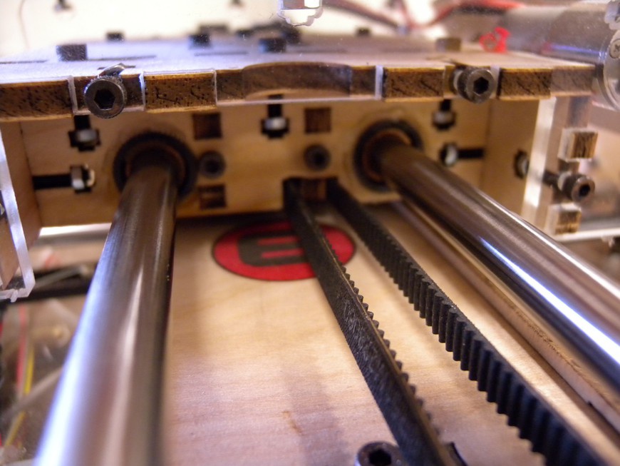
- Belt-drive mechanisms consist of a re-inforced timing belt that interfaces with a toothed pulley attached to the drive motor (Figure 7-15). As the motor rotates, the belt is fed through the pulley and pulls the carriage to the desired position. The amount of torque transferred to the carriage directly correlates to the diameter of the pulley attached to the motor. Larger pulleys produce less torque and more motion per step, whereas smaller pulleys produce more torque and less motion per step.
Linear Guides
The linear guide consists of a precision ground rod or rail that supports the axis’s carriage as it travels. The carriage couples to the guides by using either bushings or bearings, providing smooth and resistance-free travel.
- Rods
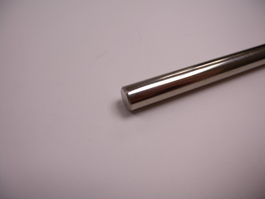
- Linear rods are made out of rigid metal and provide a cost-effective method for achieving smooth linear motion (Figure 7-16). The cheapest linear rods are made out of ceramic-coated aluminum; more robust rods are made of hardened steel. The carriage is attached to the rods by using round bushings or bearings coupled to a support structure.
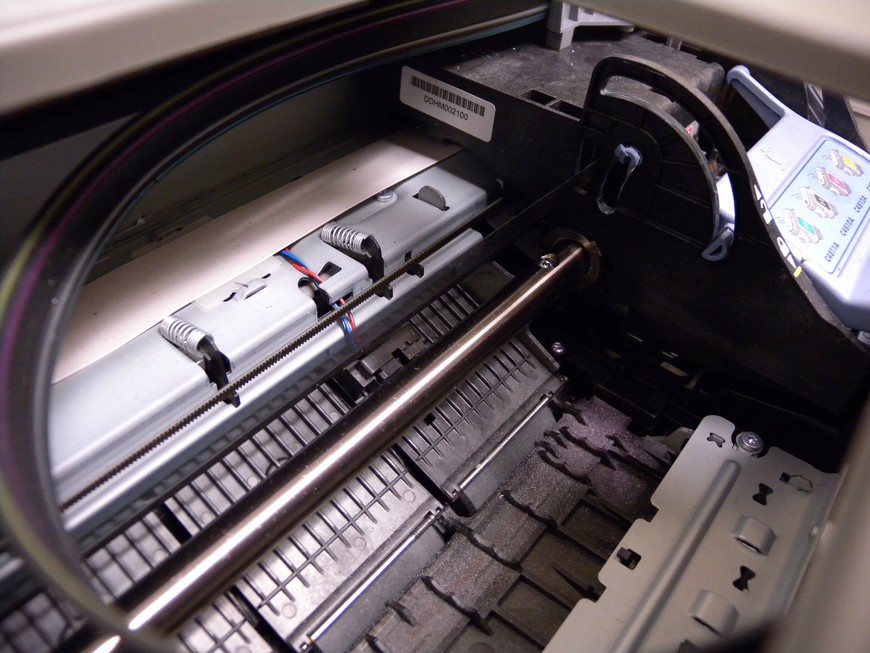
Linear rods can be scavenged from old inkjet printers (Figure 7-17). You can acquire these printers either for very little money or even free from yard sales and thrift stores. Two identical printers will produce enough components to construct a high-quality axis.
- Rails
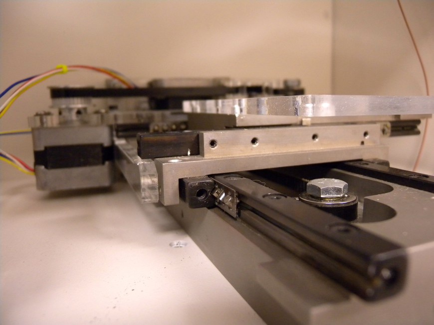
- Linear rails are designed to provide a smooth linear motion and come pre-equipped with mounting features (Figure 7-18). The carriage is attached to the rails using bearings or low-friction slides. Linear rails are often more expensive than rods but provide much greater load capacity.
- Bushings
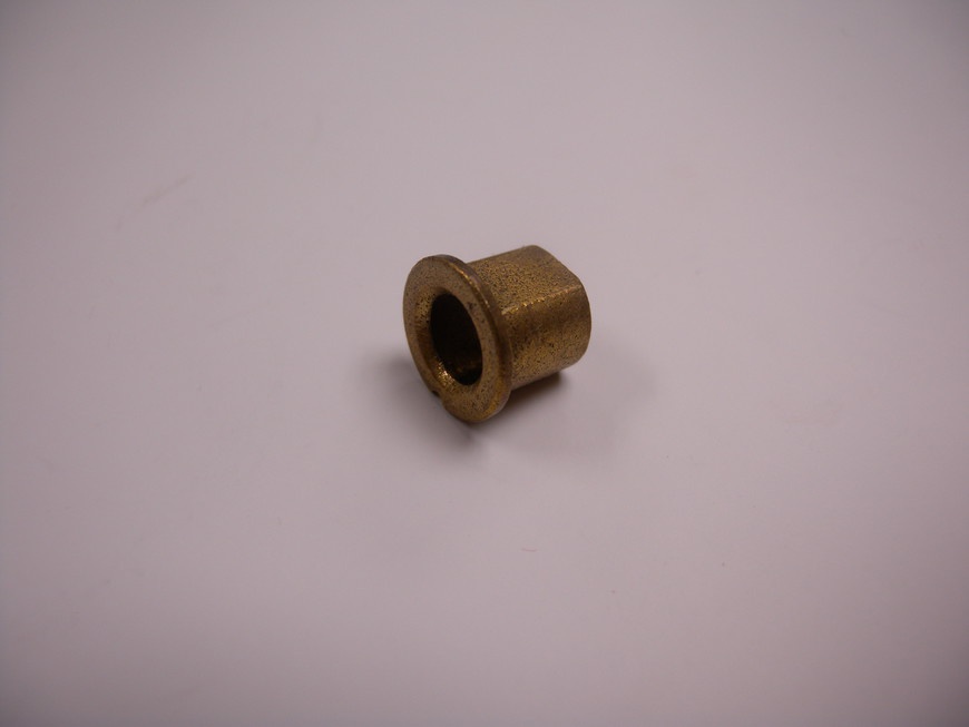
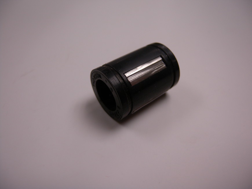
- Bushings are made of nylon, PTFE, PTFE-coated aluminum, or bronze due to the material’s strength and low friction (Figure 7-19). These devices are less expensive than bearings but provide a good method for achieving smooth axis motion at a lower cost.
- Bearings
- Bearings provide the smoothest linear motion but are significantly more expensive than bushings (Figure 7-20). Roller bearings consist of an outer roller that supports a series of hardened steel balls and a race. Either the roller or race can be secured, allowing the other to spin freely. Linear bearings consist of a series of channels filled with small ball bearings. The balls travel with the motion of the bearing, providing smooth linear motion.
Computer-Aided Manufacturing and G-Code Generation
For a computer-generated solid model to be extruded into reality, it needs a bit of processing. CNC equipment follows a tool path that is generated by Computer-Aided Manufacturing (CAM), software that is configured with all of the operational specifications for your machine. Layer by layer, the software creates a string of x and y movements and a slew of other commands that control the printer’s accessories, including the extruder and heaters.
CAM Software
There are free and open-source CAM packages available that are designed specifically for use with 3D printers (Table 7-5). Although each is unique in their own way, and some are even tailored for one specific type of machine, they all accomplish the same task. After the CAM software is installed and open, you can import solid models into the available build space. This space is represented by a three-dimensional work plane that represents the extent of the build platform. The model then needs to be properly oriented so that the base of the object is placed onto the build platform. After the build platform is populated with all of the desired parts, the CAM software utilizes its G-Code Generator to produce the code necessary for printing. The resulting G-Code is then sent to the controller via a constant data stream or local storage.
| Software Title | Platform | Link |
Windows, OS X, Linux | ||
Linux, OS X, Windows | ||
Linux, OS X, Windows | ||
Linux, OS X, Windows | ||
Linux, OS X, Windows |
The first thing everyone should print when they get their printer up and running is the beloved calibration cube. This 20 × 20 × 10 mm cube is designed to act as a quick means for determining your machine’s layer quality and height and dimensional stability.
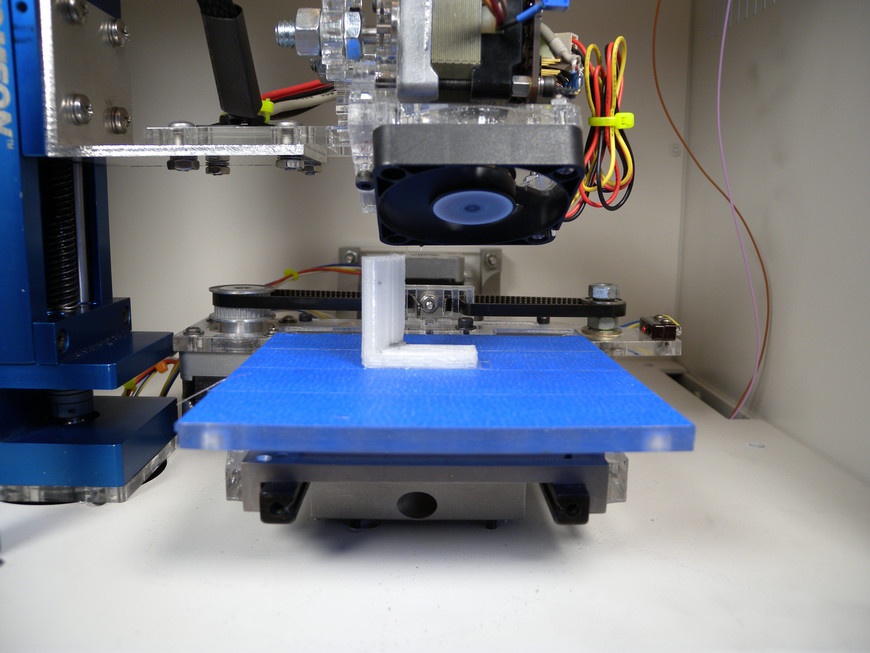
An alternative to the cube is the calibration vector (Figure 7-21). This little device serves as both a means for determining things like layer quality and height as well as enough surface area to accurately determine your axis alignment. Particularly with the z-axis, axis alignment is easy to adjust and dramatically affects build quality. You can find the files on Thingiverse.
G-Code Generator
The G-Code generator (Table 7-6) is responsible for slicing a solid model into layers that direct the 3D printer. These toolchains contain virtually every parameter required to systematically disassemble a solid model, analyze it, and reassemble it into a series of layers.
- Layer Height or Thickness
- The height of each layer is dependent both on the extruded filament’s thickness as well as the desired amount of detail in the printed object. Adjusting this setting sets the amount of lift the z-axis makes before beginning each layer.
- First Layer Height
- Because the first layer of the printed object needs to be the most robust, its height is often greater than the subsequent layers. This setting should be adjusted to optimize the first layer adhesion to the build platform and to provide proper support for the rest of the object.
- Fill Density or Infill
- The fill density setting configures the quantity of material that is deposited between the walls of the object. You might want to lower this when making test prints of a model because it greatly increases build speed. When the model is verified, the infill should be increased to between 30 and 50 percent to produce a sturdy object. For objects that need to withstand substantial forces, the infill can be increased to over 90 percent, which will result in a virtually solid object. Be careful with higher fill densities because parts tend to delaminate as the material shrinks.
- Fill or Infill Pattern
- The fill pattern settings establish the method on which the extruder fills the space between the object’s perimeter. Rectilinear is a good choice of pattern setting, producing a strong, sectioned interior structure.
- Print Speed or Feedrate
- The print speed determines how quickly the extruder moves over the build platform. It has two primary settings that adjust the speed at which the printer prints and how fast it changes position when not printing. This setting should be adjusted until optimal print results are achieved, and directly affects the flow rate. This setting is dependent on both the strength of the motors and the extruder’s ability to consistently deposit material. If the setting is too high, the extruder will not be able to keep up, which will result in thin and choppy layers or the axis steppers will skip steps, offsetting the print.
- Skirt or Initial Circling
- The skirt produces an initial outline around the perimeter of the object prior to construction. This skirt is used to prime and clear any old material from the extruder prior to printing, which contributes to significantly better print jobs.
- Raft
- The raft setting enables the addition of an initial removable base layer of material that acts as a buffer between the build platform and the model. The raft helps eliminate problems with nonlevel build platforms and improves adhesion, because the raft is made by depositing large amounts of extruded filament onto the build platform. After the raft has deposited its initial layer, one or more thin layers of material are deposited that both support the object’s first layer and allow for raft separation after printing.
- Flow Rate
- The flow rate directly relates to the print-speed setting. This setting determines how quickly the extruder prints material as it creates each layer. This setting should be adjusted until the desired layer width is achieved.
- Width over Thickness
- The layer-width over thickness setting describes how wide the layer is as it is extruded. This setting directly correlates to the flow rate and layer height because they determine how much material is deposited. You can adjust this setting after physically measuring the thickness of a single deposited extrusion.
- Support
- The support feature adds weak woven support structure to any overhanging elements and can be easily removed after the build is complete. This added material helps to prevent problems that occur when overhangs exceed the 45-degree design constraint. Printing overhangs without support results in the extruded filament sagging due to the lack of material upon which to build.
G-Code
G-Code is a numeric control language that is used to control CNC machinery. For 3D printing, G-Code consists of two command types: G-codes and M-codes. G-Codes are preparatory commands that instruct the machine where to go and how to get there (Table 7-7). M-Codes are miscellaneous commands that directly affect the controller and its interfaces (Table 7-8). These commands are assembled into a file that is streamed to the controller during operation.
- G-Codes
- G-Codes are commands that control the mechanical motion and operation of the machine. These codes contain commands that move the axis at specific print speeds to the desired locations, rotate extruders, and find endstops.
| Command | Function | Example | Notes |
Linear movement at rapid feedrate | G0 X42 | Example will rapidly move × +42 mm | |
Linear movement at previous or specified feedrate | G1 X42 F1000 | Example will move × +42 mm at X units/s | |
Sets absolute coordinates with respect to the origin | G90 | ||
Sets coordinates relative to last position | G91 | ||
Sets current position as absolute zero | G92 X50 Y50 |
- M-Codes
- M-Codes are commands that control the machine’s software. These codes contain commands that start and stop the program, set the steps/unit, and many other auxiliary functions. Some M-Codes are modal, which means they retain their setting throughout the program, whereas others complete as soon as the next line of G-Code is read.
Codes can be manually sent to the controller through a serial terminal program. The easiest method for doing this is to use the Arduino IDE and open up the Serial Monitor. Set the Line Ending to Newline and the baud rate to match the controller, and you should see startup text appear in the window. To jog your x-axis +5.0 mm, simply set the controller to relative positioning by typing G91 in the text bar and pressing Enter. You should get an OK response indicating the controller understood the command. Then type G0 X5 and press Enter; the axis should move 5 mm from its current position, and you should get an OK response from the controller.
The Controller
The CNC controller interprets a data stream of computer-generated paths into the motion of the machine’s axis while simultaneously monitoring and controlling a fleet of support hardware. The typical 3D printer control system is capable of driving 4 steppers, two heaters, and a series of sensors that determine both temperature and relative position.
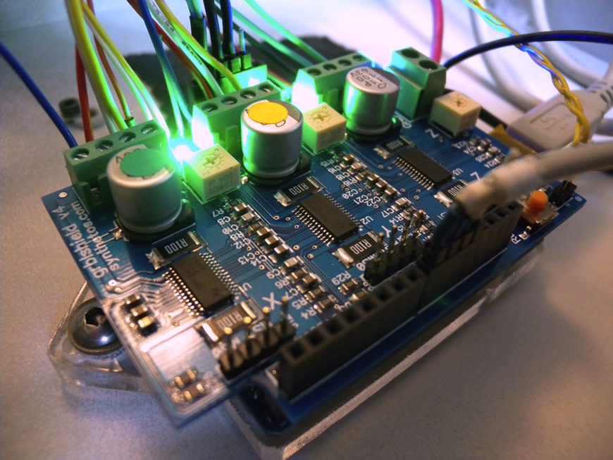
There are quite a few available control systems, such as TinyG (Figure 7-22), that are designed to support 3D printing. Each of these systems takes a new approach at providing the most amount of control for the least amount of money. Table 7-9 presents just a few of the more popular systems.
| Controller | Type | Processor | Driver | Link |
Arduino shield | Mega | |||
TinyG | Stand-alone | ATxmega192 | DRV8811 | |
Arduino shield | ATmega328 | DRV8811 | ||
Stand-alone | ATmega644P or ATmega1284P | A4988 | ||
Stand-alone | ATmega1280 | A4928 | ||
Stand-alone | AT90USB1286 | A4928 | ||
Stand-alone | ATmega1284P | A4988 |
Controller Operations
Controllers operate by reading an incoming string of commands and reacting accordingly. These commands are designed to either control the motion of the axial components or set parameters that affect the way the machine and control program operate. Each controller implements a series of features and algorithms that are designed to optimize the motion of the axis in response to each G-Code command.
The following sections describe some of the more common terminology encountered when working with G-code.
- Jogging
- Jogging refers to the actual motion of the axis and is used when manually positioning the axis by using the control software or by feeding the controller individual lines of G-Code. The distance and print speed determine the quantity of motion that is achieved.
- Ramping, Acceleration
- Ramping and acceleration refer to motion methods that are designed to optimize the speed at which the tool travels along its path. Because each axis generates a certain amount of inertia as it moves, implementing ramping and acceleration helps to alleviate problems encountered when hard stopping or starting an axis while in motion.
- Jerk
- Jerk is a derivative of acceleration and refers to the quantity of change in pressure due to variances in the acceleration. This affects the position of the tool as it travels along the path, and you can adjust it to change the quality of the extrusion during positive and negative acceleration.
Stepper Drivers
Axis motion starts with a series of electrical pulses generated by a stepper driver. This device functions as the interface between the low-power controller, whether it be a computer or microcontroller, and the high-power motors. Each driver issues a series of electrical pulses that pull the rotor in a clockwise or counterclockwise rotation, or hold position. This requires a great deal of power to achieve and is one of the reasons most stepper drivers are actively cooled during operation.
Most stepper drivers consist of an dedicated integrated circuit (IC) that is designed specifically for driving stepper motors and other support electronics that promote stable operation. This includes a pair of current-sensing resistors with which the driver can sense how much current is flowing into the stepper, a potentiometer to adjust the allowed current output, and often a pair of microstepping jumpers. The driver is controlled over three primary control lines: enable, step, and direction. The enable pin is used to activate power to the driver’s motor outputs. This makes it possible for the driver to hold the motors in position and prevents unintended axis movement. The step input triggers the driver to move the rotor one step and can be triggered at an exceedingly high rate. Some stepper drivers can even be controlled with a modulated frequency. The direction pin sets the direction, whether clockwise or counterclockwise, and the rotor is stepped and controlled with a HIGH or LOW condition on the input line.
You can adjust each driver to increase or decrease the quantity of current made available to the motor. This adjustment is very important to make; having too much current can result in choppy motion and can overheat the motor, whereas too little current might result in missed steps or motor stall. To adjust the current, locate the potentiometer on the stepper driver and set it to the lowest position. Send a command to jog that axis at a low print speed by using the software control panel or during a print if your printer has the capability. While sending the jog command, gradually increase the current until the axis begins to move freely, without hesitation. Stop jogging and the current level should be set. If you notice the axis stalling during normal operations, gradually add more current until the problem is resolved. Remember, it is better to have less rather than more current.
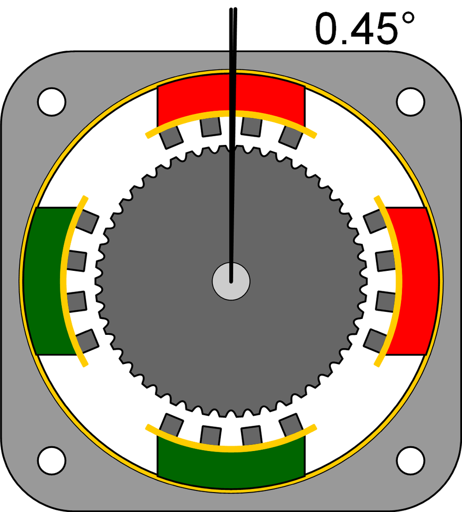
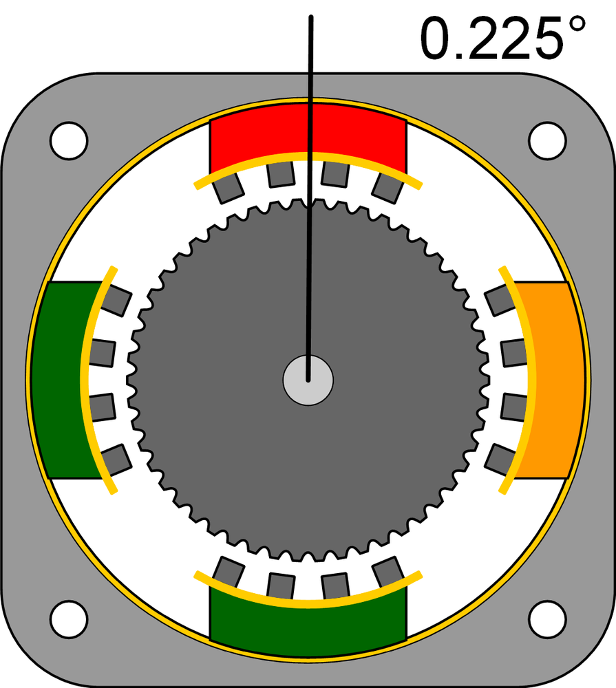
The stepper driver can operate on one of three primary modes of operation: full-stepping, half-stepping, and microstepping.
- Full-Step Mode
- Full-step mode is motion that is achieved when only one phase is activated at a time (Figure 7-23). This pulls the rotor in line with that phase’s coil, and the next coil is activated. If the stepper motor has 200 steps per rotation, each step in full-step mode would result in the rotor turning 1.8 degrees. The benefit of full-step mode is that the stepper motor functions with its maximum rated torque, while sacrificing resolution.
- Half-Step Mode
- Half-step mode is motion that is achieved when the coils are energized by alternating between one phase and both phases (Figure 7-24). The result is a doubling of the steps per rotation. So, if the stepper motor has 200 steps per rotation in full-step mode, it would have 400 steps per rotation and each step would result in the rotor turning 0.9 degrees. The drawback of half-step mode is the torque fluctuation between one or both phases being energized. This fluctuation is accommodated for, depending on the driver.
- Microstepping Mode
- Microstepping mode is the most complex of the three modes (Figure 7-25) and is the one enabled on most 3D printers. It requires the driver to servo the current sent to alternating phases with respect to a mathematical function. This makes it possible for the stepper motor to step with resolutions at a fraction of a step resulting in a significant increase in steps per rotation. Each microstepping divisor determines how much the step is divided, which can be as great as 256. This would result in a stepper requiring 51,200 steps per rotation! The drawback of microstepping mode is a loss in accuracy between steps as the divisor increases and an increase in component cost.
Endstops
Endstop sensors are used by CNC equipment to maintain repeatability and to prevent travel past the mechanical limits of the axis. These sensors detect either the maximum or minimum axis position and relay this information back to the controller in the form of a HIGH or LOW condition. There are four main types of endstops that can be used and each have unique strengths. Regardless of type, the endstop is a critical component for maintaining peak machine performance and product quality.
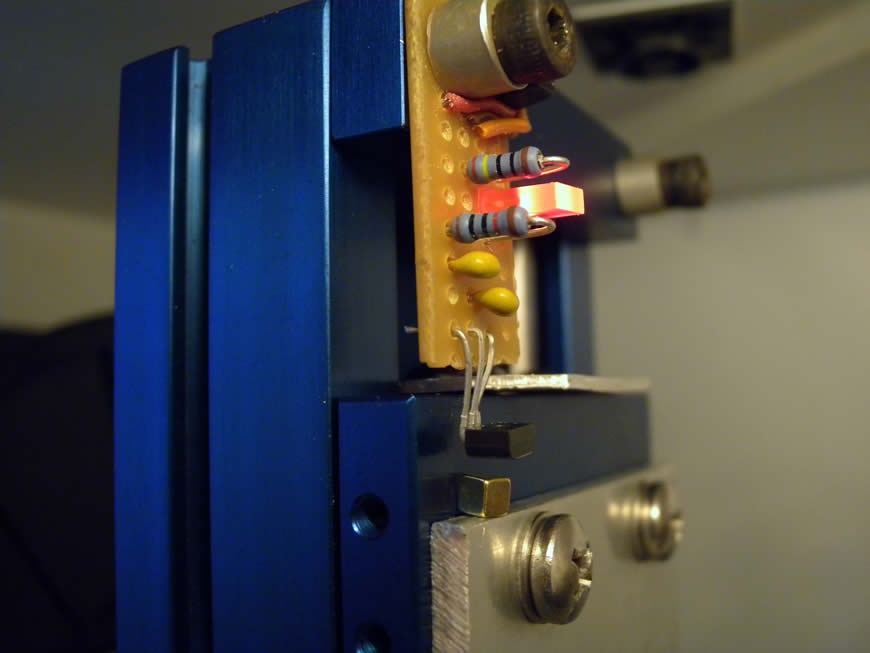
- Hall Effect
- Hall-effect endstops utilize a latching hall-effect sensor that detects the presence and strength of a magnetic field (Figure 7-26). These devices consist of two components, a magnet and a sensor, and provide a noncontact method of determining the position of an axis. The endstop produces a digital ON/OFF signal when a magnet attached to the axis comes within a set proximity of the sensor. These devices provide a reliable alternative to mechanical switches, which tend to wear out over time. Care must be taken to prevent accidental switching from nearby magnetic fields, like those produced by motors.
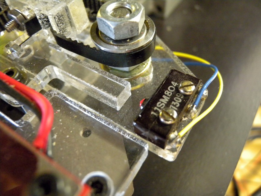
- Mechanical Limit Switch
- Mechanical limit switches utilize a spring-metal leaf connected to a plunger mechanism that, when depressed, completes the circuit between two contacts (Figure 7-27). There is a fair amount of variation in how the switch is activated and can greatly affect switching accuracy and repeatability. Table 7-10 illustrates the various types and how they are actuated.
| Type | Actuation |
Pin plunger | In-line |
Roller plunger | Slide and cam |
Leaf | Slide and cam |
Roller leaf | Slide and cam |
Lever | Slide and cam |
Roller lever | cam |
- Optical
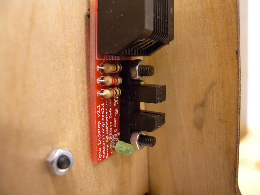
- An optical switch utilizes a light source—typically an infrared LED—and a phototransistor that switches ON and OFF in response to beam exposure (Figure 7-28). Optical switches can be configured to sense when an object breaks a light beam between the transmitter and receiver or transceiver and a reflector, or when light is reflected back when an object intersects the beam. They provide excellent resolution and stability, and when used in the transmitter/receiver configuration, they work great with 3D printers.
Project: Mechanical Centering, Alignment, and Calibration
Ensuring the proper centering, alignment, and calibration (Figure 7-29) of each axis eliminates many dimensional errors encountered when 3D printing. Axes are centered by determining the machine’s travel limits and establishing a center point. This is most important for the xy-axis because it dictates the center of the build platform. Alignment is accomplished by adjusting the relative angle of the axis with regard to the other two axes. Calibration determines the margin of error between the desired steps/unit of travel and the actual.
Materials
| Makerspace Tools and Equipment |
3D Printer with Computer |
Caliper |
Small drill press table vise |
Square |
Center Each Axis
- Step 1
- Determining the center point (Figure 7-30) of each axis makes it possible for you to properly place your parts within your control software and maximize your usable build area. Begin by opening your printer’s control software and home the axis. This sets the 0-point and serves as the first reference point. Place a piece of paper onto the build platform and lightly tape it in place.
- Step 2
- Jog the z-axis so that it sits about 1 mm above the build platform and make a small pencil mark on the paper, just below the tip of the nozzle. Jog the x-axis away from the endstop until it reaches its maximum travel and then make another mark. Jog the y-axis away from the endstop until it reaches its maximum travel and make the final mark. Repeat this process for the z-axis by using a caliper or ruler to measure the vertical travel.
- Step 3
- Use a ruler or caliper to measure the length of each line. Divide this length in half to determine the midpoint and then enter the values into the control software configuration.
Determining Alignment
- Step 1
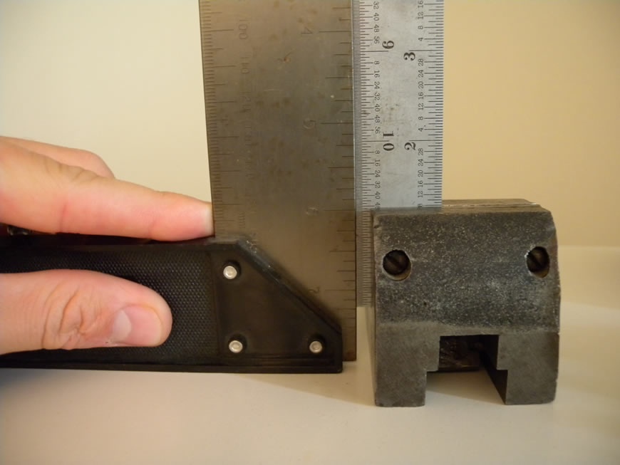
- Ensure that your printer is set on a flat and level surface to begin alignment. The worktable will function as the starting reference point. From there, you can properly align each axis and determine how level the build platform is. Secure the square into the jaws of the vise and reference its trueness to a second square that’s positioned on the tabletop (Figure 7-31). This ensures that the square secured in the vise will serve as an accurate reference.
- Step 2
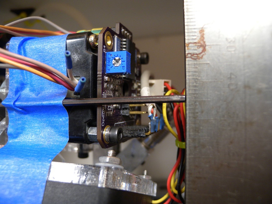
- Attach an indicator rod to the z-axis by which to measure offset and lower the axis to its lowest position (Figure 7-32). Position the clamped square in line with the z-axis extension and slowly raise the z-axis. As the z-axis travels, note any change in the distance of the z-axis extension relative to the square. Any deviation will indicate a misaligned z-axis, and you should make adjustments accordingly. Test and retest both the x and y side of the z-axis to verify alignment.
- Step 3
- The alignment of the x- and y-axis are not dependent on z alignment but do dictate the levelness of the build platform. On machines with build platforms attached to the z-axis, you can make the adjustment by placing a piece of paper between the tip of the nozzle and the top of the platform. Check the gap at all four corners of the platform as well as the middle and make adjustments accordingly. For designs that feature a moving platform, leveling is a bit more tricky. Start by determining the levelness of the x-axis by using a caliper to measure the distance from the top of one x-axis guide to the top of the table. This measurement will serve as the reference and should be used to adjust the other three guide ends. Repeat this step to align the y-axis relative to the table.
- Step 4
- Lay the square onto the build platform and move the x- and y-axis to their minimum positions. Power on the machine and use the control software to lower the extruder until the nozzle just touches the edge of the square. Carefully jog the platform or extruder down the length of the square so that it remains in line with the extruder. This aligns the square to the travel of the x-axis and serves as reference for the y.
- Step 5
- Without moving the square, position the nozzle at the end of the square and jog the extruder or platform down the length of the y-axis. Adjust the guide rails until there is no longer any deviation from the square. Repeat steps 3–5 until the x- and y-axis are properly aligned.
Determining Calibration
- Step 1
- Power up the 3D printer and open the control software or terminal. If you are using the terminal, set the machine to relative positioning by using the G91 command. The calibration of each axis is determined by comparing the desired motion to the actual motion of the axis. You then use this number to calculate the actual steps/unit and is fed into the control software for proper G-Code processing or into the controller’s firmware for proper axial control.
- Step 2
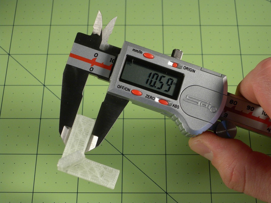
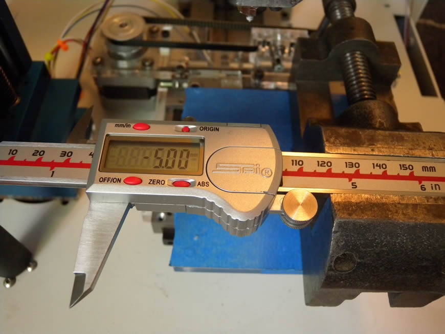
- Center each axis and lock the motors. Carefully secure the caliper in the jaws of the vise so that the dial carriage can slide freely and the depth gauge extends along the axis you are calibrating. Extend the depth gauge by sliding the dial carriage to the side until it touches a fixed surface perpendicular to the axis, such as the side of the printer, an endstop, and so on. Rotate the dial so that the indicator points to 0 or press the Zero button on the caliper (Figure 7-33).
- Step 3
- Unlock the caliper and jog the axis 0.50 in (5.0 mm), closing the caliper. The caliper should then compress and the difference between the desired motion and actual motion determined. Record the actual steps/unit and adjust the control software accordingly. Repeat this procedure for each axis until calibration is complete.
3D Printing
3D printers produce physical objects from virtual models by using a process commonly known as fused filament fabrication. This process involves the extrusion of molten plastic filament that is systematically deposited onto a build platform. Layer by layer, the machine outlines and fills each element until the entire object has been replicated. When the object has cooled, it can be separated from the platform and put to use.
The filament extruder deposits plastic by using a toothed, or hobbed, filament feed wheel in combination with a tensioner. As the feed wheel turns, filament is gripped by the teeth and forced into the barrel located at the base of the extruder. A heater heats the barrel to the temperature required for extruding, which varies depending on plastic type. When the plastic has reached extrusion temperature, the feed wheel forces more plastic into the barrel, in turn pushing molten plastic through a nozzle. Nozzle diameters range in size from 0.3 mm to 1.0 mm and mainly dictate the speed and resolution of your prints.
Extruder Mechanics
Extruders are made up of three primary components: the drive mechanism, the feed mechanism, and the heated barrel. These three components work in conjunction to deposit the desired amount of plastic onto the build platform and should be able to do so for hours and hours. This harsh work environment constrains the types of materials used to build the extruder. Especially within the heated barrel where temperatures are high and fluctuate constantly.
The Drive Mechanism
Feeding filament into an extruder requires a significant amount of force. This force is commonly generated by a stepper motor because of its compact size and step precision. Alternative methods use DC motors and encoders to determine print speed and position, but they add complexity to the system. On most compact extruder designs, the drive motor is attached directly to the feed mechanism via a pair of drive gears. These gears increase the torque delivered to the feed mechanism allowing for a smaller and less powerful stepper motor to be used. The size and ratio of the gears can be calculated based on the desired steps per rotation of the feed wheel and the overall torque applied by the stepper.
You can use the following formula to determine the approximate steps/mm of filament fed into the extruders and it’s a good starting point for tuning your printer:
Steps/mm = R × r / (π * D)
R | Quantity of steps per revolution at the motor |
r | The gear ratio (rfeed / rmotor) |
D | Feed wheel diameter |
The quantity of microsteps per revolution is determined by multiplying the degrees per step by the microstepping multiplier. As an example, a stepper motor that rotates at 0.9 degrees per step and is driven with a 4x microstepping multiplier will require 1,600 steps per rotation. The gear ratio is relative to the desired steps per millimeter of extrusion. The most common ratio is 39:11, and when paired with a 7 mm feed wheel, produces approximately 258 steps/mm.
Alternatively the formula can be reworked to solve for the gear ratio. If the extruder were to produce 360 steps/mm, had a 7 mm feed wheel, and was configured for 3,200 steps/revolution, the required gear ratio would be approximately 2.5:1. You can then scale this ratio to accommodate appropriately sized gear, yielding an 8-toothed drive and a 20-toothed driven gear.
The Feed Mechanism
Creating a reliable feed wheel and tensioner pair is the most complex component of an extruder. Without good grip and control, the reliability and accuracy of the extruder is compromised resulting in poor-quality builds.
- Hobbed Bolt
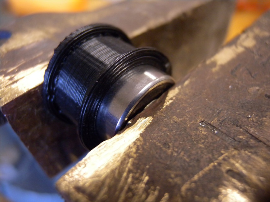
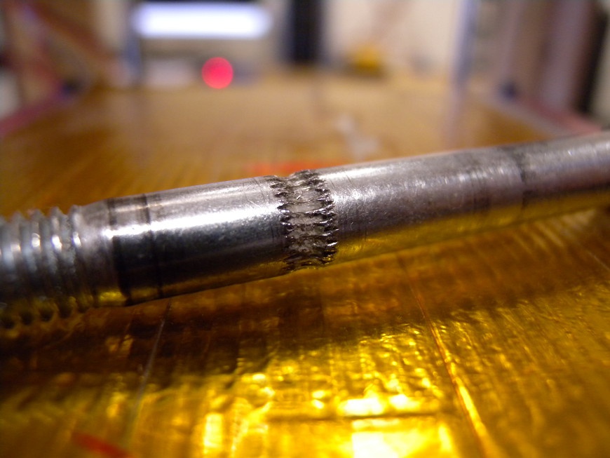
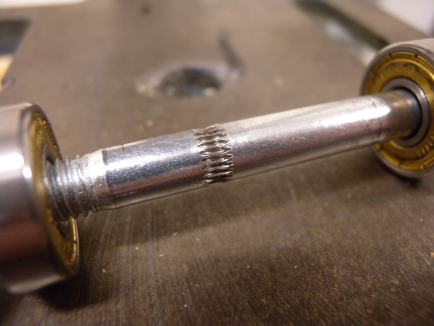
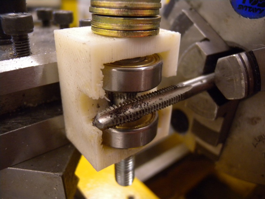
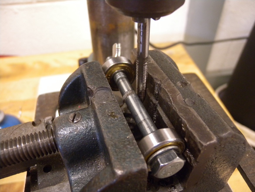
The quickest method for making a feed wheel is to use the same bolt that is attached to the extruder’s driven gear. You can add horizontally cut teeth to the unthreaded portion of the bolt making for a cheap and reliable alternative to a professionally machined feed wheel. These teeth can be added to the bolt in a process known as hobbing, which uses a spinning cutting tool to cut parallel teeth into the material as it turns. Rather then using a proper hobb cutting tool, a thread cutting tap can function as a suitable replacement and can reliably hobb bolts when chucked in a drill press or a lathe.
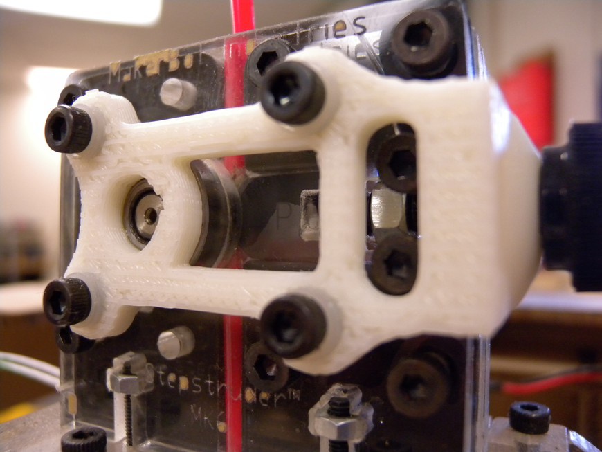
Hobbed bolts and machined feed wheels are prone to clogging (Figure 7-34) when the filament jams. An easy method for removing stuck filament is to use a wire brush and gently brush along the teeth. You can remove stubborn material with a razor, but take care not to damage the teeth.
- Machined Feed Wheel
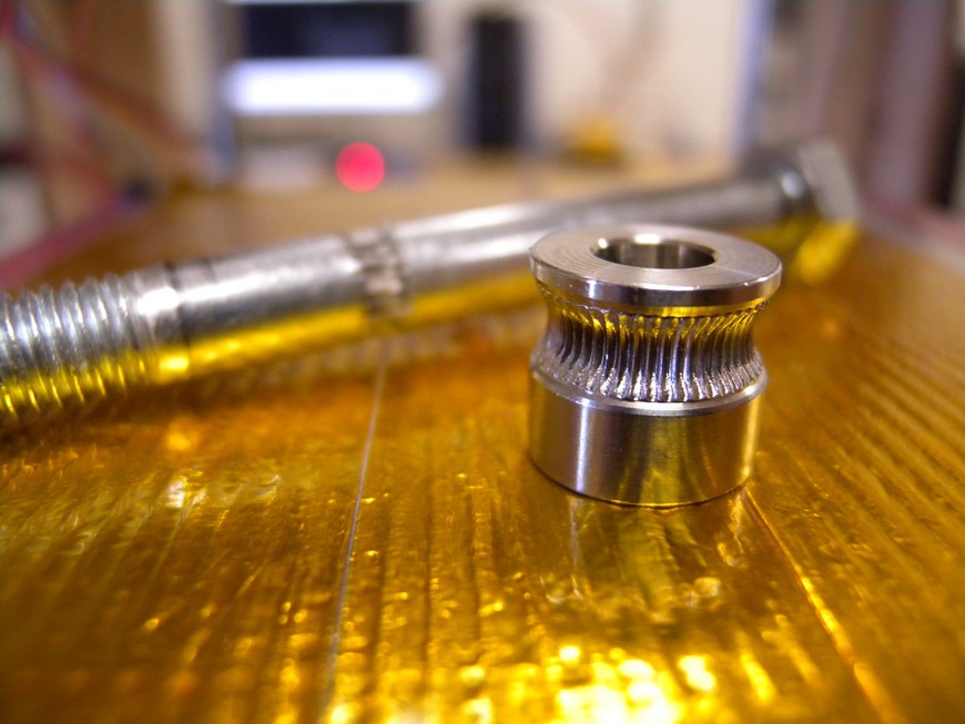
- A better alternative to the hobbed bolt is the machined feed wheel (Figure 7-35). This device functions in the same manner as the bolt, but because it is not cut by hand, it features much higher diameter and thread consistency. Depending on the extruder design, the machine feed wheel can be directly attached to the drive motor or even mounted onto the driven gear’s bolt, providing more torque with a smaller motor.
- Tensioners
- Working in conjunction with the feed wheel, the tensioner is designed to push the filament into the feed wheel’s teeth, placing as little resistance on the feed wheel as possible (Figure 7-36). The most optimal mechanism for the tension consists of an adjustable assembly that forces a bearing against the filament. The more passive approach consists of an adjustable piece of nylon or polyoxymethylene, due to its strength and low friction coefficient.
The Heated-Barrel Assembly
The heated-barrel assembly is designed to accept filament from the feed mechanism and elevate it to a temperature high enough to accommodate extrusion. Reaching this temperature involves a combination of components that isolate the hot and cold sides of the extruder, allow for continuous material flow, generate a substantial amount of heat, and provide monitoring and control. When all of these components function as intended, a thin, consistent extrusion of plastic can be generated for many hours on end.
- Barrel
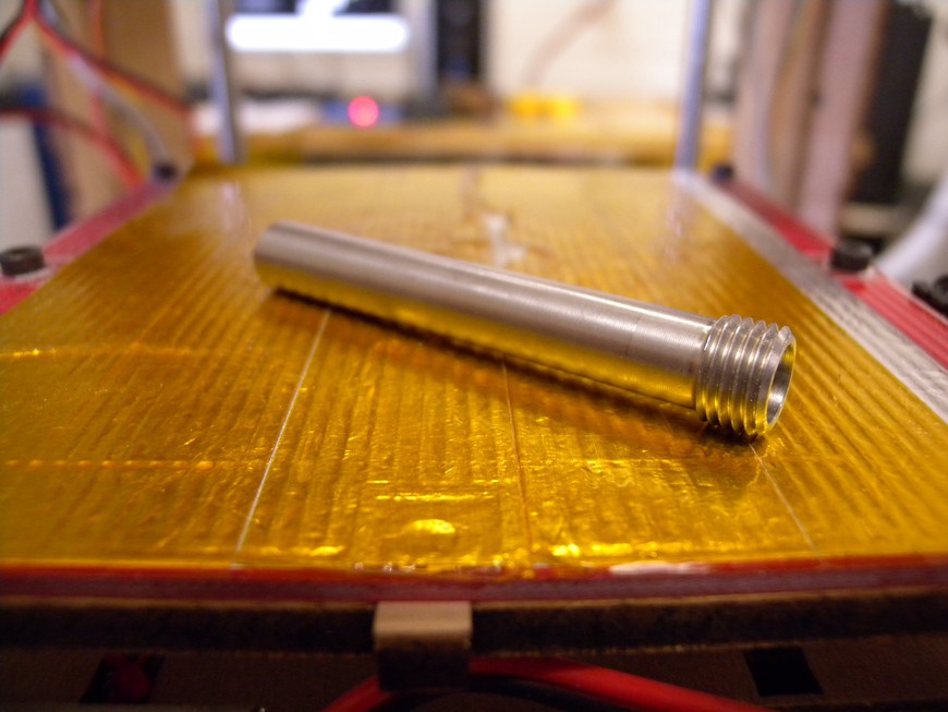
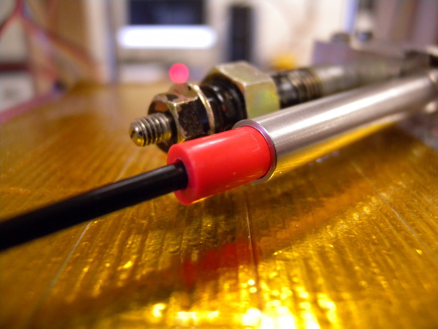
The barrel itself has two roles (Figure 7-37). The first of which is to physically isolate the hot end of the extruder from the rest of the device. This is important because there are many problems that can occur when too much heat rises up the barrel. One of which causes the filament to soften and ultimately jam the feed mechanism. To prevent problems like this, the barrel should be made out of a material that is not only strong, but doesn’t thermally conduct. There are three materials that are commonly used to solve this problem: PEEK, PTFE (Figure 7-38), and stainless steel. PEEK and PTFE are rigid polymers that can withstand temperatures up to 250°C and have low friction coefficients. Stainless steel is often used because it provides good structural support and resists corrosion.
The inside of the barrel contains a PTFE tube that separates the barrel’s structure from the filament. If the filament were to contact the side of the barrel, it would cool, resulting in a filament jam.
- Nichrome Heater
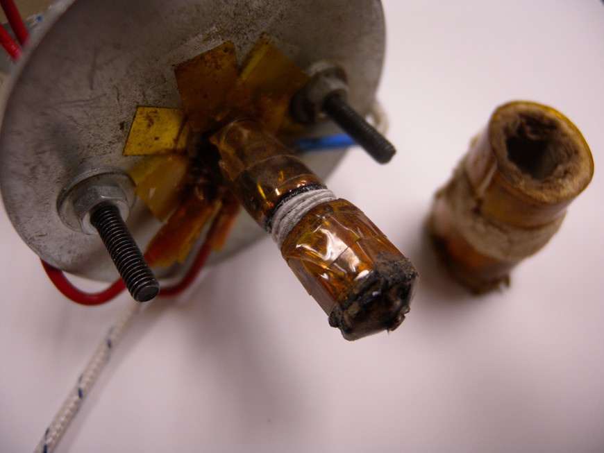
- Nichrome is a nickel-chromium alloy that is used in heating elements due to its natural resistivity and ability to withstand high temperatures (Figure 7-39). The two most common alloys are nichrome A (80 percent nickel and 20 percent chromium) and nichrome C (60 percent nickel, 16 percent chromium, and 24 percent iron). Nichrome A features a lower resistivity that is more stable over temperature fluctuations, whereas Nichrome C features higher resistivity that varies more with temperature. Each wire thickness delivers a known Ohms/ft(m) that can be used to calculate the length of wire required to make the desired heater (Table 7-11).
| Gauge | NiCr A (Ω/m) | NiCr A (Ω/ft) | NiCr C (Ω/m) | NiCr C (Ω/ft) |
25 | 6.64 | 2.02 | 6.89 | 2.1 |
26 | 8.38 | 2.56 | 8.69 | 2.65 |
27 | 10.61 | 3.23 | 11 | 3.35 |
28 | 13.35 | 4.07 | 13.84 | 4.22 |
29 | 16.81 | 5.12 | 17.43 | 5.31 |
30 | 21.15 | 6.45 | 21.93 | 6.68 |
31 | 26.92 | 8.21 | 27.92 | 8.51 |
32 | 34.38 | 10.48 | 35.65 | 10.87 |
33 | 42.4 | 12.94 | 44.01 | 13.42 |
34 | 53.71 | 16.37 | 55.7 | 16.98 |
35 | 68.2 | 20.79 | 70.72 | 21.56 |
- Soldering Nichrome
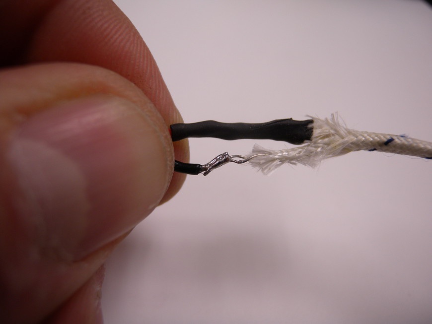
- One of the problems faced when using nichrome to make a heater is attaching the heater’s power wires to the nichrome (Figure 7-40). Nichrome inherently does not bond to solder using conventional electronics soldering flux. This problem can be overcome by using fluxes designed for soldering stainless steel because they also include chrome. Care must be taken when using these fluxes because they contain a large quantity of hydrochloric acid, which is severely caustic and must be removed from the solder joint to prevent corrosion. Take time to review the Material Safety Data Sheet (MSDS) prior to use. Alternatively, you can attach nichrome to the power wires by using crimp connectors. This method involves wrapping a small amount of nichrome around the ends of the power wires and crimping the joint in place with a crimp connector. Although the resulting joint works, it is prone to failure resulting from repeated vibration and flexion.
- Cartridge Heater
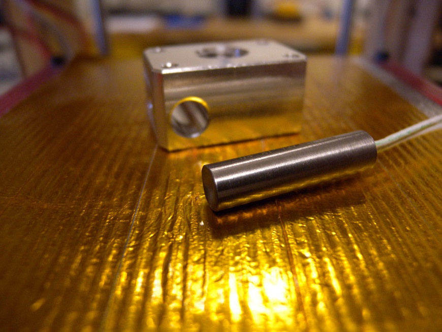
Cartridge heaters contain a coil of nichrome wire encapsulated in a sturdy stainless-steel tube (Figure 7-41). The high-temperature power leads extend from one side of the element and are bonded to the inside of the cartridge, providing strain relief and extending the heater’s lifespan. Because the cartridge cannot be wrapped around the heater barrel, a secondary structure is needed. This “heater block” attaches to the base of the barrel and often serves as the mount for the nozzle.
It just so happens that the automotive industry is a source of reliable heaters. Diesel engines use a glow plug (Figure 7-42) to preheat the cylinder to assist with starting the engine. The Autolite 1104 is the perfect combination of size and power for 3D printing, consuming approximately 25 watts at 5 VDC and costing less than half the price of a conventional element heater. You must take care when using this type of heater because they can reach temperatures high enough to start fires.
- Power Resistor
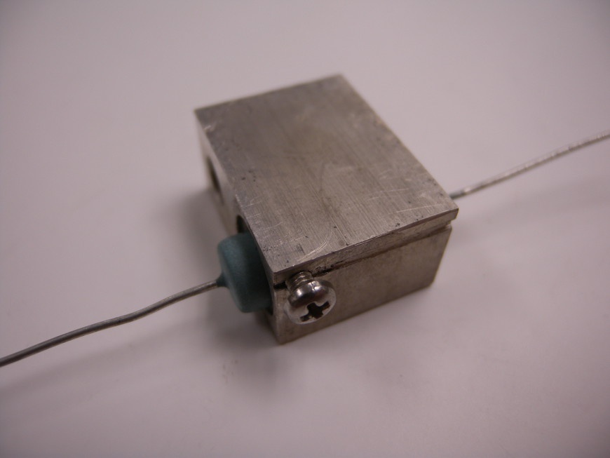
- The cheapest and easiest solution for heating the barrel is to use a 3-watt wire-wound resistor (Figure 7-43). These resistors are designed to dissipate 3 watts of power in open air. When embedded in a heater block in the same manner as a cartridge heater, the conductivity of the block makes it possible for the resistor to dissipate more power without failing. These resistors are typically made using a nichrome wire wound around a ceramic or fiberglass core and can handle some pretty intense heat. Typical resistance values are 6.8 Ohms, producing ~21 watts at 12 VDC, and 5.6 Ohms, producing ~26 watts at 12 VDC. These resistors are more prone to damage than their cartridge heater counterparts but cost significantly less.
- Nozzle
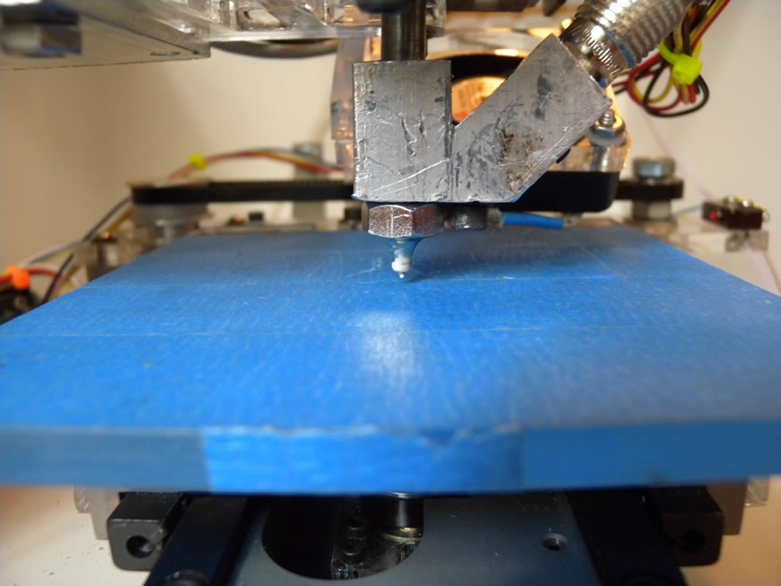
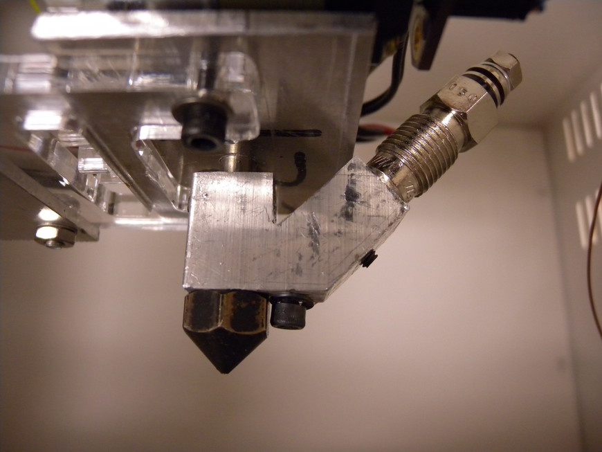
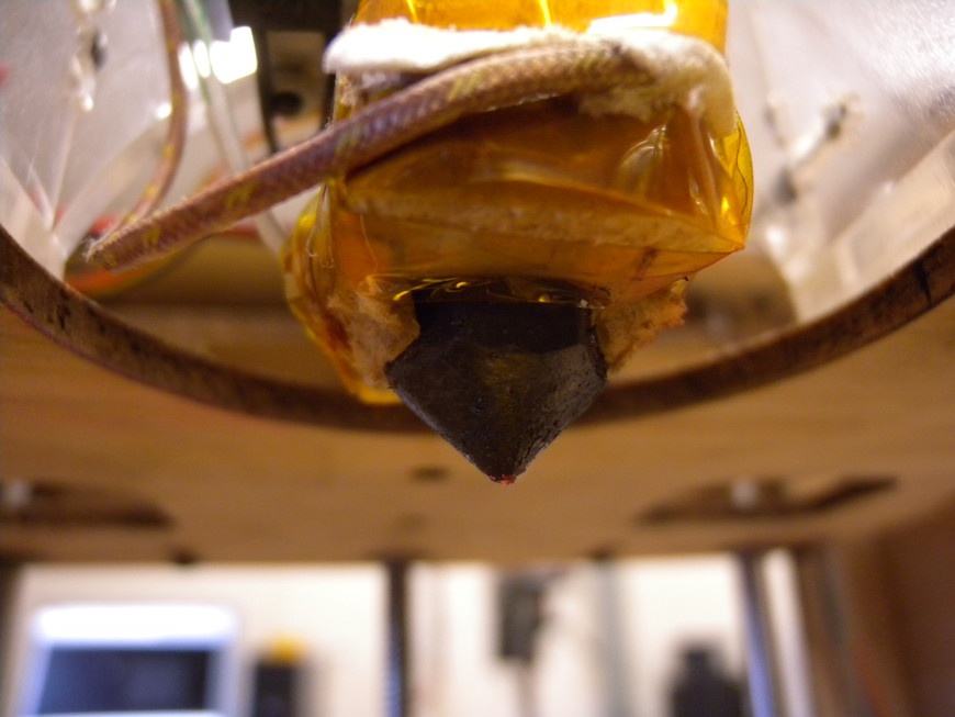
- Nozzles function by tapering the large diameter filament to a desired extrusion diameter that is typically less than 1 mm (Figure 7-44). With designs that use a threaded barrel and nichrome wire, the nozzle has female threads and is screwed onto the end of the barrel. With designs that use a cartridge or power resistor, the nozzle has male threads and is screwed into the heater block. Most nozzles are made out of brass because of its high thermal conductivity and machinability.
Brass acorn nuts and hex-head bolts provide a good starting point for machining a nozzle. The nut or bolt can then be bored and drilled using a drill press or lathe until the desired measurements are achieved.
- Temperature Sensing
- It is important that the temperature of the molten filament is precisely controlled. Variances of only 1°C directly affect the material’s flow and can result in inconsistent builds. To accurately monitor the temperature of the filament, extruders feature a thermal sensor that is connected as close as possible to the nozzle. Thermistors and thermocouples are commonly used here because they provide accurate thermal sensing over a wide temperature range. These sensors then relay the values back to the temperature controller, which then modulates power to the heater as it maintains temperature.
Material Types
There are a variety of material types that 3D printers can extrude. The material comes as a long extruded filament typically 1.5 to 3.0 mm in diameter and is fed directly into the extruder. The type of material used ultimately depends on the end application, and each one has unique advantages. The most common materials used for 3D printing include ABS, PC, PLA, PVA, and FRO.
RepRap.org publishes a long list of material suppliers, including cost per kg/lb. To view this list, go to http://reprap.org/wiki/Printing_Material_Suppliers.
ABS
Full name | Acrylonitrile Butadiene Styrene |
Extrude temperature | 195°C–245°C |
Glass transition | 95°C |
Decomposition temperature | 260°C |
Acrylonitrile Butadiene Styrene (ABS) is a low cost thermoplastic plastic that is easily extruded and provides good dimensional stability. Primarily used in the automotive industry, ABS lends itself to 3D printing, producing parts that are rigid but not brittle. The filament is available in a wide variety of colors, even glow-in-the-dark.
Because ABS is derived from petroleum products, it is not biodegradable like PLA and produces unpleasant fumes when heated. These fumes can cause nausea if overexposed. If the Makerspace is going to allow the use of ABS filament, ensure that proper ventilation has been installed or switch to a less-offensive filament.
PLA
Full name | Polylactic acid |
Extrude temperature | 190° C–230°C |
Glass transition | 60°C |
Decomposition temperature | 250°C |
Polylactic acid (PLA) provides a welcomed alternative to ABS because it is fully biodegradable and produces less offensive fumes when extruded. This polymer is derived from corn starch and is slightly harder and more brittle than ABS. One of the downsides to PLA is that it is hygroscopic (it absorbs moisture), which can lead to extrusion problems. When the water content is too high, bubbles tend to form in addition to inconsistencies in viscosity. These problems are not permanent and can be prevented by storing unused PLA in a dry box or by removing the moisture in a drying oven.
PLA also has a significantly shorter residence time than ABS. If the PLA sits in the extruder for too long while heated, the color and flow properties will be negatively affected, resulting in a brown hue and bubbles. A good remedy for this problem is to perform a purge of the resident plastic prior to building.
PVA
Full name | Polyvinyl alcohol |
Extrude temperature | 160°C–170°C |
Glass transition | 85°C |
Decomposition temperature | 200°C |
Polyvinyl Alcohol (PVA) is a polymer found in the food industry because it is fully biodegradable and dissolves quickly in water. Relatively new to Makerspace 3D printing, PVA has shown its usefulness as support material and for making water-soluble parts. If the PVA is left in the heater for too long, or it is exposed to temperatures above 200°C, the material will jam the nozzle. These jams are very hard to remove and often require nozzle replacement.
PC
Full name | Polycarbonate |
Extrude temperature | 250°C–280°C |
Glass transition | 146 C |
Decomposition temperature | 380°C |
Polycarbonate (PC) is a strong and impact resistant thermoplastic that requires relatively high temperatures to extrude. Due to these high extrusion temperatures, you must take care to ensure that the extruder will not fail. PC is also hygroscopic and thus will absorb moisture over time, resulting in the same extrusion problems as with PLA.
Wood
Extrude temperature | 180°C–230°C |
This relatively new material is comprised of wood shavings and a binding polymer that is compatible with PLA and ABS extruders. You can print it at relatively low temperatures and it does not require a heated bed. The resulting prints look, smell, and have the characteristics of any wooden object.
Frosting
Extrude temperature | 20°C |
Glass transition | 20°C |
Decomposition temperature | 29°C |
Plastic isn’t the only thing a 3D printer can extrude. Many Makerspace bakers have turned to edible material extrusion. With the use of a frosting-compatible extrusion system, 3D printers are capable of frosting and decorating delectables.
The Build Platform
The build platform provides the starting point for every 3D printed object. It is designed to provide both level support for the build as well as to a bonding surface that prevents the material from shifting and warping as each layer is deposited. To counteract problems with adhesion and warping, many build platforms use designs and materials tailored specifically for each material type.
Platform Design
Thermal expansion and contraction of a material plagues the world of 3D printing. As the extruder deposits material onto the build platform, its molten state has greater volume than when solidified. This difference in volume results in the material changing shape as it cools, often resulting in the part warping and separating from the build surface. There are three methods to counteract this problem: heat the interior of the 3D printer to a temperature high enough to prevent distortion, heat the build platform, or rapidly cool the filament.
- Heating the Environment
- This method is the most complex and is often only employed with commercial 3D printers. The entire 3D printer is enclosed in a thermally insulated case that is heated by convection. A fan inside the printer blows air past a temperature-controlled heating element that raises the temperature high enough to prevent the material from warping and separating from the build platform. For DIY printers, this environmental heating can be accomplished by enclosing the entire printer in a thermal insulation.
- Heating the Build Platform
- The most common method for 3D printing materials such as ABS is to actively heat the build platform. This is accomplished by routing a heating element beneath the platform and monitoring its temperature with a thermistor. Some designs use a nichrome wire to provide heating, but you should avoid these due to the nichrome’s potential to generate enough heat to ignite the platform, damaging the machine and potentially the surrounding area. A better alternative to nichrome is to use a circuit board with a network of traces designed to produce enough resistance to function as a heater. Because the build platform does not need to reach exceedingly high temperatures, this design provides safer and more reliable heated surface.
- Actively Cooling the Filament
- Some materials such as PLA can be directly deposited without the need for heating the build platform. This makes for a much less complicated system because two controls, the surface heater and the temperature monitor, are eliminated. For the material to adhere to the surface and not separate when cooled, the extrusion can be slightly cooled immediately after extrusion. You can accomplish this by attaching ductwork and a small fan that blows cool air directly at the extruder’s tip. If the extrusion cooled too much it will prevent the layers from bonding. Conversely, if the extrusion remains too hot, it will contract too much when cooled and separate from the platform.
Build Platform Materials and Coatings
Getting hot extrusion to bond to the build platform is not a trivial task. Some bond best when the platform is heated, others do not. Some require special surface coatings, whereas others are less picky. Choosing the proper surface material is just the first step. It then needs to be fine-tuned to prevent the extrusion from sticking too well or not enough. When the configuration is complete, print jobs can proceed with little separation during printing but still be easy to remove upon completion. Table 7-12 lists several printing materials and the platform materials with which they’re compatible.
| Printed Material | Platform Material | Heated |
ABS | Polyimide | YES |
Painter’s tape | YES | |
PC | Polyimide | YES |
PLA | Acrylic | NO |
Painter’s tape | NO | |
Polyimide | YES | |
Polycarbonate | NO | |
PVA | Polyimide | YES |
- Heated
Heated build platforms can be made from materials with good thermal stability and rigidity, including glass, aluminum, and circuit board. Glass platforms provide a good starting point for a build platform and you can use them with or without polyimide or PET adhesive. Glass withstands high temperatures, is mostly level, and very inexpensive. One of the problems faced when using glass is its relatively low thermal conductivity, which can make temperature adjustment a bit tricky. Attach the thermistor to the top of the bed rather than the bottom when used as a heated platform. This helps to more accurately measure the surface temperature. Glass also has the tendency to crack when unevenly heated. You can avoid this by using an aluminum plate between the glass and the bed heater. Because aluminum is a good conductor of heat, it will spread out any hot spots produced by the heater and provide for a more evenly heated platform. The cracking problem can also be solved by using tempered glass. This glass is heat treated and can withstand temperatures and stresses well beyond that of standard glass.
Printed circuit boards can be used as a heated platform by combining the heater, thermal sensor, and structure into one unit. The circuit board material, typically FR4, has good thermal conductivity, thus you can locate the heating element on the top or bottom of the platform. The surface must be coated with either polyimide or PET adhesive to promote extrusion adhesion. The addition of a thin plate of aluminum to the top of the circuit board provides better heat spreading and surface characteristics.
Aluminum provides an excellent surface for printing. Its high thermal conductivity and structural integrity means that it can accommodate large prints with little separation. As with the glass and circuit board designs, aluminum needs to be coated with either polyimide or PET film to promote adhesion. One of the complexities of using aluminum as a build platform is its electrical conductivity. Applying a heating element directly to the bottom of the plate without insulation will result in an electrical short and thus requires isolation. You can do this by tracing the path of the heating element first with a layer of polyimide tape and then place the element. Or, simply by using a heater that is already electrically insulated.
Many scanners use a sheet of tempered glass for the scanner bed. A quick trip to the thrift store can yield an old scanner, complete with glass bed, for the same price as a sheet of nontempered glass.
- Unheated
- Plastics like acrylic, ABS, and polycarbonate are suitable for nonheated platforms. These materials provide very good adhesion properties that often result in difficulty separating the printed object from the surface. Coating the surface with painter’s tape helps lower adhesion and provides an inexpensive method for maintaining the surface quality. One of the drawbacks of using plastic beds are inconsistencies in thickness and the tendency of the material to bow. These can be avoided by using material at least 1/4 in thick and frequently checking that the platform is level.
Applying a thin coat of cooking oil to the surface of the platform with a clean rag can help lower adhesion, making separation easier.
- Coatings
You can coat build surfaces with adhesives that promote adhesion. These adhesives include painter’s tape, PET tape, and polyimide tape. Painter’s tape is an excellent surface coating due to its low cost and availability. The wax content in the tape promotes adhesion of most extruded materials both with and without heated platforms. Although painter’s tape is less durable than other adhesives, its excellent performance and low cost easily make up the difference.
PET, or polyester, film tape is a relatively new material to be used with heated build platforms. This adhesive exhibits approximately the same durability as polyimide tape and has an operating temperature less than 200°C.
Polyimide film tape is a popular surface coating due to its durability and ability to withstand extreme temperatures. This orange tape bonds well to most surfaces and comes in a wide range of widths, lengths, and thicknesses, making it possible for some platforms to use only a single piece of adhesive. Although polyimide is an excellent coating, it is relatively expensive and over time looses its adhesion qualities.
Project: Bolt Hobbing
The drive wheel is the single most important component in an extruder because it provides the mechanical interface between the drive motor and the filament. If there are distortions or unevenness in its design, the filament will not feed evenly, resulting in poor print quality. There are two methods for producing consistent hobbed bolts (Figure 7-45) that will yield hassle-free printing, and both of them can be carried out by using Makerspace equipment.
This project requires that safety glasses be worn throughout its entirety.
Materials
| Materials List | ||
Item | Quantity | Source |
8 × 22 mm ball bearings | 2 | Sporting goods store |
M8-1.25 partially threaded bolt | 1 | Home improvement store |
M8-1.25 nut | 2 | Home improvement store |
M8 washer | 2 | Home improvement store |
| Makerspace Tools and Equipment |
Drill press |
Lathe |
Safety glasses |
M4-0.7 Tap |
Making a Hobbed Bolt Using a Lathe
To hobb a bolt by using a lathe (Figure 7-46), you’ll need a special bolt holder. The irony of this process is that unless the bolt holder is made by hand, a 3D printer is required.
- Step 1
- Search Thingiverse.com for a bolt holder that is compatible with your lathe and use a 3D printer to print it with 100 percent infill. This ensures that the holder is as strong as possible. Install and secure the tap into the jaws of the chuck so that the threaded portion is left exposed. Position the bolt holder into the lathe’s tool holder and tightly secure in place. Position the bolt holder such that the bolt is perpendicular to the tap.
- Step 2
- Use a permanent marker to mark the desired position of the hobbed section onto the unthreaded portion of the bolt. Place two bearings into the holder and slide the bolt into place. Without powering the lathe, move the carriage so that the bolt is positioned approximately 1 mm from the nontapered end of the tap and verify the alignment. Use washers to adjust the alignment and, when set, secure the bolt in place with a nut followed by another. Tightening the second nut will jam the first in place, preventing it from loosening.
- Step 3
- Configure the lathe to the appropriate RPM for cutting steel. Apply a layer of cutting oil to the tap and turn on the lathe so that the chuck is spinning toward you, or counterclockwise. Slowly move the carriage along the y-axis until the bolt comes into contact with the tap. Apply just enough force to allow the tap to cut and rotate the bolt. Continue cutting until the cuts just meet, resulting in sharp peaked teeth. Cutting too little will result in teeth that are not sharp enough to grip filament, whereas cutting too deep will weaken the teeth. After cutting is complete, back off the carriage and turn off the lathe. Remove the bolt from the holder and wipe off any filings and remaining cutting oil. The hobbed bolt is now ready for action. Install it into your extruder and start printing!
Making a Hobbed Bolt Using a Drillpress
A simpler yet less precise method for producing a hobbed bolt requires only a drill press and a table vise (Figure 7-47).
- Step 1
- Begin by marking the position of the desired hobbed section onto the unthreaded portion of the bolt and slide on two bearings. Position the assembly into the jaws of the table vise so that the bearings sit about an inch away from each side of the marked line and rest on the base of the vise. Tighten the jaws of the vise to secure the assembly in place. Do not apply too much pressure or you will distort the bearings, preventing the bolt from rotating. Secure the bolt in place with a nut followed by another to lock the first nut.
- Step 2
- Determine the desired diameter of the feed wheel and insert a drill bit with the same size upside down into the chuck. This drill bit acts as a gauge for positioning the vise onto the table of the drill press. Place the vise onto the table and position it so that the drill bit touches the side of the bolt and is aligned with the mark. Secure the vise in place by using a clamp and remove the drill bit from the chuck. Install the tap and apply a liberal amount of cutting oil to the cutting area.
- Step 3
- Turn on the drillpress and slowly lower the spindle until the tap begins to contact the bolt. Pressure is applied between the bolt and tap by slowly lowering the spindle and increases with the taper of the tap. This process requires a bit of finesse, and you must be careful not to lower the spindle too quickly. Apply enough pressure to engage the tap with the bolt so that the bolt begins to rotate as the teeth are cut. The key to this process is to work slow enough so as to not flex the tap but quick enough so that the blot turns as the tap cuts. Continue this process until the desired threads are formed. Remove the bolt from the holder and wipe off any filings and remaining cutting oil. The hobbed bolt is now ready for action. Install it into your extruder and start printing!
