Chapter 8. Learning in a Makerspace
Education is evolving and the idea of teaching with micromanufacturing technology is now a reality. Students are more responsive and retain more knowledge when they can connect the class work to the world in which we live. Yet students in the K–12 public education system are hammered with theoretical concepts that lack relevancy beyond the classroom, or are not taught in a way that makes them relevant. It is really not surprising that a good percentage of students lack the ability to apply their classwork to physical applications. It is imperative that we establish avenues for students to learn through hands-on exploration. This age of the Makerspace will serve as the catalyst for inspiring future minds in engineering and will act as an outlet for today’s most creative individuals Figure 8-1.
Makerspace Education
Public school systems need Makerspaces. No longer should a school’s poor financial resources limit access to the equipment necessary for higher-level exploration. It is now possible for a classroom—even one with a very small budget—to provide an environment conducive for utilizing and learning prototyping, robotics, electronics, microprocessors, and the like. Initially, the most logical location for a school-based Makerspace is within the technology education and engineering classrooms. The staff have been trained on managing students in a workshop environment and the addition of Makerspace technology in the classroom is a natural fit.
This chapter’s labs are designed to provide a starting point for getting students more involved in the technical aspects of your curriculum. Each K–12 lab activity harnesses the power of Makerspace technology in a way that allows the students to be more involved in the learning process. It helps to eliminate “black box” technology and gives the students more responsibility and ownership of their work. Each section contains labs categorized as a “Technical Lab,” an “Activity,” or a “Learning Tool.” Technical Labs contain further investigation after the lab is complete. Activities do not contain an investigation and can serve as the starting point for a more technical lab. Learning Tools are tools that instructors can use in the classroom to help support theoretical concepts.
The labs are broken into three categories:
- Kindergarten through 5th Grade: The teacher makes the parts using Makerspace technology and walks the students through each step of their use.
- 6th through 8th Grade: The teacher helps the students make the parts, and the students then use them.
- 9th through 12th Grade: The teacher demonstrates the equipment’s use and the students design and make the parts.
Achieving “STEM” Focus
Today’s increased interest in science, technology, engineering, and math (STEM) courses was intended to boost interest in our technical workforce. The irony of this movement derives from the fact that the only required courses in STEM are science and math. And being required courses, they have required curriculum with standards testing to verify student comprehension. Updating the curriculum requires imaginative teachers who can both inject new and interesting topics into the coursework while hitting all of their benchmarks.
What About Art?
Art in STEM? Preposterous! Understanding the fundamental concepts of art in the design and creation of physical objects is imperative to success in STEM fields. Technology and engineering courses tackle design through both physical and software-based illustration. Courses such as basic technical drawing and architecture teach students to use manual drafting tools to visually represent their designs. Students can convey their ideas and reflect on possible design changes, thus making their designs more feasible. With computer-aided design tools such as AutoCAD, Solidworks, and AutoDesk Inventor, students can design the parts and assemblies that can be directly translated into real-world objects. Using tools such as these, students can make the connection between the virtual and physical worlds and see how design affects someone’s ability to actually build something.
The Rhode Island School of Design has an excellent website dedicated to information and news concerning the integration of art and design into STEM education.
So, all in all, it really ends up on the quality of the program and the emphasis the individual teacher puts on the integration of art into their curriculum. Art is incredibly important and more effort should be made in education to excite students about art, music, dance, theater, and so on. STEM education is designed to help increase excitement and interest in the fields of science, technology, engineering and math, all of which can benefit from the creativity art courses promote.
Makerspace Science
The science classroom offers a tremendous potential for utilizing Makerspace technology. The following labs are designed to enhance a student’s experience within a science classroom by introducing common topics through hands-on investigation:
Lab #1: Making a Lemon Battery
- Subject
- Science
- Grade Level
- K–5
- Lab Type
- Technical Lab
- Estimated Class Time
- 45 Minutes
- Objective
- This lab focuses on developing and applying an understanding of conventional battery technology. Through hands-on investigation and experimentation, students will explore different methods for producing low-power biological batteries and measuring their power output.
This project requires that safety glasses be worn throughout its entirety.
Overview
The earliest form of the battery consisted of a clay pot, a copper cathode and zinc anode, and a simple electrolyte solution. Although the exact uses of the battery are still a mystery, we can replicate this transformative technology in the classroom. A low-power battery can be safely made by modeling the use of copper and zinc and replacing the pot with a lemon (Figure 8-2).
When the zinc is suspended in an electrolyte solution—in this case, water and citric acid—small particles of zinc dissolve into the electrolyte. This process frees electrons that can power a very small electronic device such as an LED. Now, if the copper is also placed into the same electrolyte solution and the LED is connected between the two plates, a chemical reaction occurs that frees yet more electrons. You can measure the amount of energy produced by this simple battery by using a multimeter and calculate just how big of a device you can power. Who knows, maybe you could run your school on lemons! (Or, as the old saying goes: when life gives you lemons, power your school with them.)
The LED used in this lab requires 1.5 V and 20 mA of current to fully illuminate, and on average a good lemon battery will produce 0.5 VDC and 10 mA. Because the lemon battery does not produce enough power on its own to illuminate the light, more than one is needed. Multiple lemon batteries can be configure either in series or in parallel to meet the power requirement.
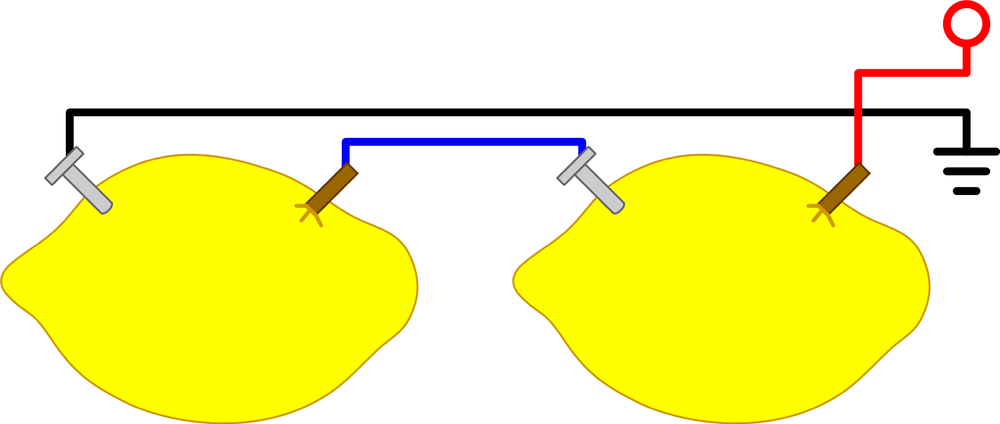
Connecting the batteries in series (Figure 8-3) increases the overall voltage. Each battery’s voltage is added but the current stays the same. To configure lemon batteries in series, connect the positive terminal on one battery to the negative terminal on another. This is known as “daisy chaining,” and you can continue adding more batteries in this fashion until the necessary voltage is achieved. The free terminal on the first and last batteries become the battery bank’s positive and negative sides.
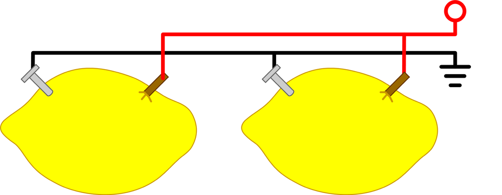
Conversely, connecting the batteries in parallel (Figure 8-4) increases the overall current, but the voltage remains the same. To configure lemon batteries in parallel, connect the positive terminals and negative terminals of two or more batteries together. You can continue adding batteries like this until the necessary current is achieved.
Materials
| Materials List | ||
Item | Quantity | Source |
Lemon | 1 | Grocery store |
Copper penny | 1 | Pockets, under seat cushions, and so on |
4D zinc-coated nail | 1 | Home improvement store |
Alligator test leads | 2 | Electronics distributor |
5 mm LED | 1 | Electronics distributor |
Plastic knife | 1 | Grocery store |
1 × 1 in 200-grit sandpaper | 1 | Home improvement store |
| Makerspace Tools and Equipment |
Multimeter |
Safety glasses |
Setup
- Step 1
- Begin by placing your lemon on a stable work surface and gently roll it back and forth. This process will help produce the electrolyte base you require to make a good battery by releasing all of the internal citric acid-containing juices.
- Step 2
- Gently clean the surface of the penny with your sand paper so that it is bright and shiny. This process removes oxidation that will reduce the power of the battery. Now, using the plastic knife, carefully make a cut through the lemon’s skin about 1/2 in wide and 1/2 in from the end of the lemon. Insert the penny so that approximately 1/8 in. is left exposed.
- Step 3
- Insert the zinc-coated nail into the lemon, about 1/2 in from the opposite end of the lemon as the penny.
- Step 4
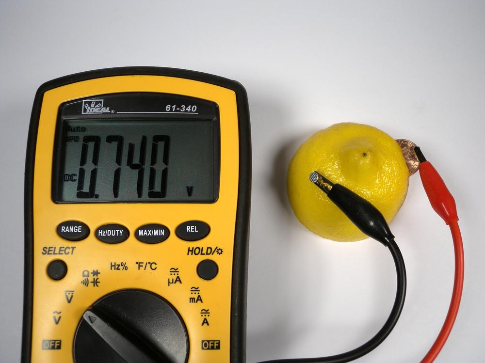
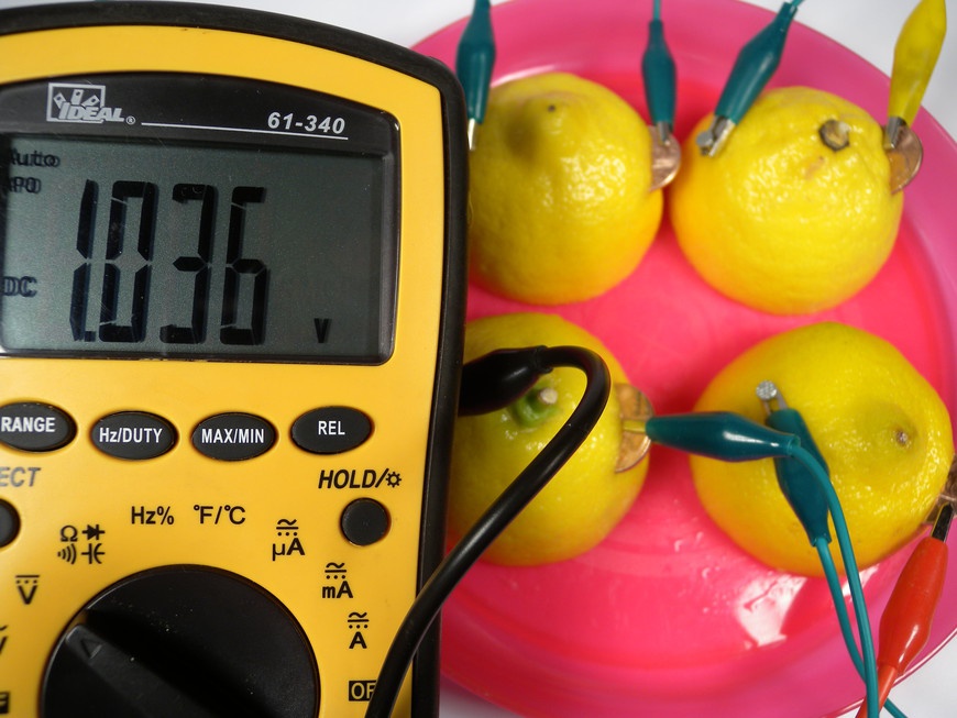
- With the help of your instructor, configure the multimeter to measure volts DC (VDC). Touch one lead to the penny and one to the nail. If you see numbers on the screen, congratulations—you just made a battery out of a lemon! Now, lets take some measurements (Figure 8-5).
Investigation
The electric capability of your battery is measured in terms of voltage and current. To understand this capability, you will need to collect data that reflects its power output potential by using a multimeter.
- Determine Polarity and Voltage
A battery has two sides, positive and negative. Following the same procedure as described in step 4, touch one of the multimeter’s leads to the penny and one to the nail. If the numbers on the screen are negative, your leads are connected backward. Flip your lemon around and try again.
- Is the penny the positive or negative side?
- Is the nail the positive or negative side?
- How much voltage is produced?
- Determine the Current
With the help of your instructor, configure the multimeter to measure milliamperes (mA). Touch the multimeter’s red lead to the positive end of the battery and the black lead to the negative.
- How much current is available?
- Lighting an LED
Connect one alligator test lead to the end of the nail and one to the exposed part of the penny. You’ll use these leads to connect your LED to the lemon battery. Now, connect the negative side of your battery to the negative side of the LED as indicated with a black stripe and the positive side of the battery to the positive side of the LED.
- Did the LED light up?
Remember, the LED requires approximately 1.5 V and 20 mA to glow. If your battery produces 0.5 V and 10 mA, how many batteries in series and parallel would you need in order to light the LED?
- Number of batteries in series
- Number of batteries in parallel
Working with one or more other students, configure your batteries to produce enough energy to illuminate the LED.
Lab #2: Making a Solar Cell
- Subject
- Science
- Grade Level
- 6–8
- Lab Type
- Technical Lab
- Estimated Class Time
- 1+ Hours
- Objective
- This lab demonstrates the production and use of a light-sensitive semiconductor in the formation of a primitive solar cell. Copper is used to produce a naturally occurring semiconductor, cuprous oxide, which forms on the surface of copper when exposed to high heat.
This project requires that safety glasses be worn throughout its entirety.
Overview
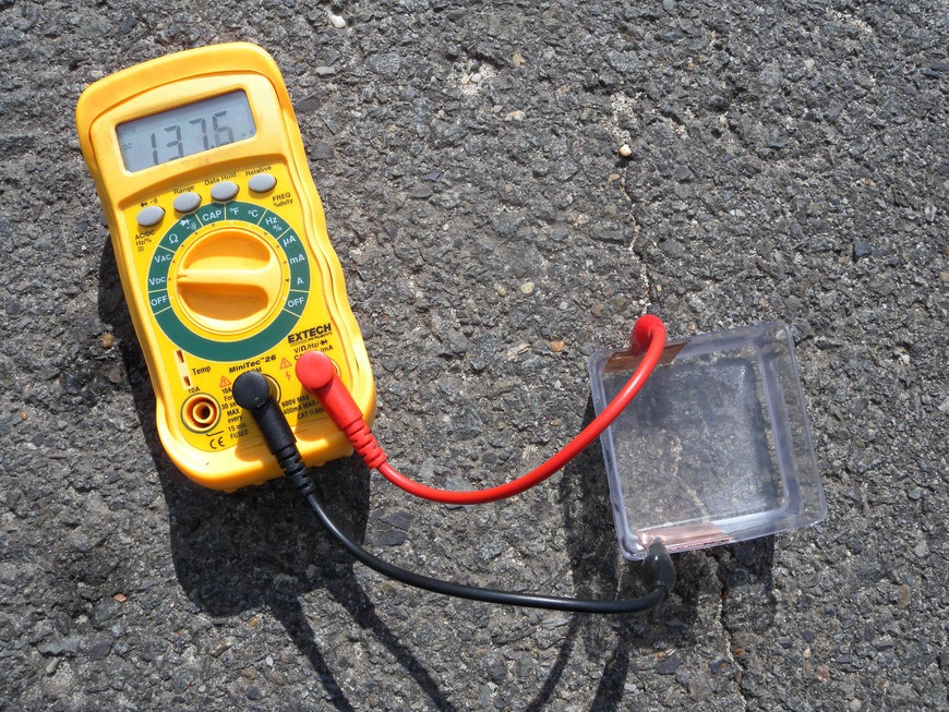
Solar cells, or photovoltaics, are made out of photosensitive semiconductors that convert light energy into electricity in a process known as the photoelectric effect. This process describes the interaction between light energy and the materials that make up the individual cell. Although commercial solar cells are made by using harmful chemicals and require sophisticated equipment for assembly, you can make a simple low-cost solar cell (Figure 8-6) in your lab with only a few materials.
Materials
| Materials List | ||
Item | Quantity | Source |
Table salt | 1 tbsp | Local grocery |
White vinegar | 1 cup | Local grocery |
Distilled water | 1 cup | Local grocery |
Small plastic cup | 1 | Local grocery |
Thin copper sheet | 2 | Home improvement store |
Alligator test leads | 2 | Electronics distributor |
| Makerspace Tools and Equipment |
High-temperature hot plate |
Micrometer |
Nonflammable work surface |
Multimeter |
Safety glasses |
Tweezers |
Setup
- Step 1
- Place the hot plate on a nonflammable surface and preheat it to 500°F. Ensure that there is enough free area around the hot plate for placing the heated copper.
- Step 2
- Cut the copper sheet into 1 × 1 in squares. Each solar cell will require two pieces. Remove the existing oxidation and dirt from the surface of the copper using a cleaning solution made with vinegar and water. In a cup, mix 1 cup of vinegar and 1 tbsp of table salt until the salt has completely dissolved.
- Step 3
- Create a grid on a piece of printer paper and assign labels for the rows and cells so that there are enough spaces for the number of students in the class.
Procedure
- Step 1
- Measure the surface area of the copper pieces using the dial caliper. This measurement will be used to determine the solar conversion efficiency.
- Step 2
- Using the supplied cleaning solution, carefully remove the insulating oxide and dirt on the surfaces of both of your copper pieces. Add a small amount of the solution to the paper towel and rub the copper until shiny. One piece is going to act as the positive and the other the negative.
- Step 3
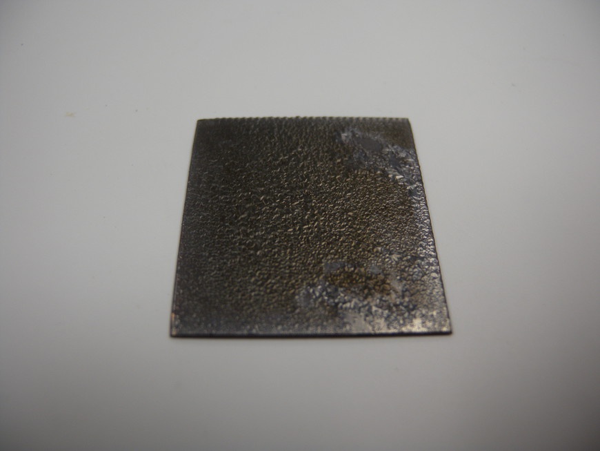
- Locate one grid space on the provided sheet and place only one of your pieces in the cell. The instructor should place the piece onto the hot plate. As the copper heats up (Figure 8-7), observe the formation of the red cuprous oxide and then the resulting formation of black cupric oxide, an insulator that will be removed at the end of the heating cycle. When the cupric oxide has completely covered the surface of your piece, the instructor turns off the hot plate and allows the copper to cool down. During this time the cupric oxide should begin to flake off. Let the copper cool before handling.
- Step 4
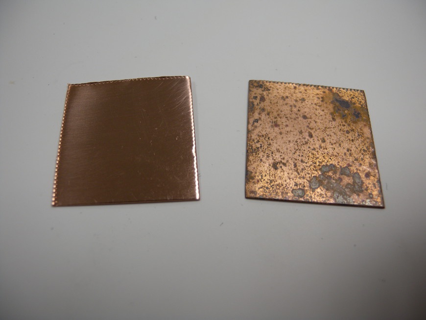
- Carefully clean away the resulting cupric oxide with sandpaper to expose your cuprous oxide semiconductor. Do not remove the multicolored cuprous oxide (Figure 8-8) during this cleaning process!
- Step 5
- Prepare a solution of distilled water and 1/4 tsp of salt in your plastic cup, making sure that all of the salt has dissolved. Carefully attach your test leads to each piece and submerge them into the salt solution. Take care that the copper pieces do not touch.
Investigation
Now that you have successfully made a primitive solar cell, it’s time to determine how much energy it can generate. Using a multimeter, you will be conducting a series of tests to determine the polarity, voltage output, current capability, and overall efficiency.
- Determine Polarity and Voltage
A solar cell has two sides: one positive and the other negative. Connect your multimeter’s negative (black) lead to one test lead and the positive (red) lead to the other test lead. Configure your multimeter to measure VDC and adjust the scale accordingly. If the numbers on the screen are negative, your leads are connected backward.
- Is the penny with cuprous oxide the positive or negative side?
- How much voltage is produced?
- Determine the Current
Configure the multimeter to measure current and adjust the scale accordingly.
- How much current is available?
- Determine the Efficiency
The sun produces approximately 1,000 W/m2 of light energy. Determine your solar cell’s energy conversion efficiency by dividing your W/m2 by that of the sun’s. Remember, Watts = Current × Voltage.
Lab #3: Making a Microscope
- Subject
- Science
- Grade Level
- 9–12
- Lab Type
- Learning Tool
- Estimated Class Time
- 1.5 Hours
- Objective
- The microscope is one of the most sensitive tools found in the science classroom. Its glass slides and clean lenses require careful handling to give students a glimpse into the microworld around us. With a little help from a Makerspace, the students can create a simple microscope using only a few cents’ worth of materials.
This project requires that safety glasses be worn throughout its entirety.
This project works with very hot materials and should only be conducted under the supervision of a qualified individual.
Overview
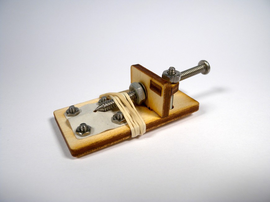
During the late 1600s, Anton van Leeuwenhoek began developing single-lens microscopes (Figure 8-9) that were capable of magnifying objects to more than 200 times their actual size. This incredible invention led to the discovery of numerous microorganisms and cell types.
Materials
You can find the files for this project at Thingiverse.com.
| Materials List | |||
Item | Quantity | Cost | Source |
1 × 2 × 1/8 in plywood | 1 | Craft store | |
1/8 × 2 in wooden dowel | 1 | Craft store | |
4-40 × 2 in pan-head machine screw | 1 | Home improvement store | |
4-40 Nut | 2 | Home improvement store | |
#4 Washer | 1 | Home improvement store | |
5 mm × 6 in glass stirrer | 1 | Scientific supply company | |
Rubber band | 1 | Home improvement store |
| Makerspace Tools and Equipment |
Countersink bit |
Heat-resistant gloves |
Laser engraver |
Wire strips |
Wood glue |
Propane torch or Bunsen burner |
Safety glasses |
Setup
- Step 1
- Open the scope.dxf file in your CAD software suite and create an array for the quantity of microscopes that you want to make. Follow your laser cutter’s operating procedure for 1/8 in plywood. Position the sheet of plywood on the cutting bed, send your drawing to the machine, power on the exhaust fan and air assist, and begin cutting.
Procedure
- Step 1
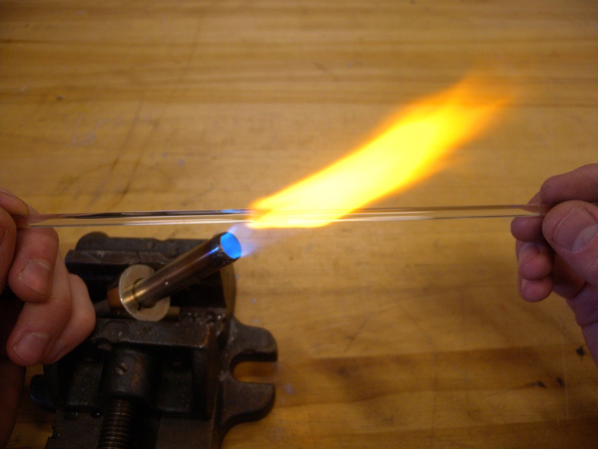
- Put on your safety glasses and heat-resistive gloves. Ignite the torch and adjust the flame so that it is about 2 in length. Grip the stirrer approximately 1 in from each end and insert the middle of the rod into the flame. Ensure that the rod is positioned at the top of the blue cone, which is the region with the highest temperatures.
- Step 2
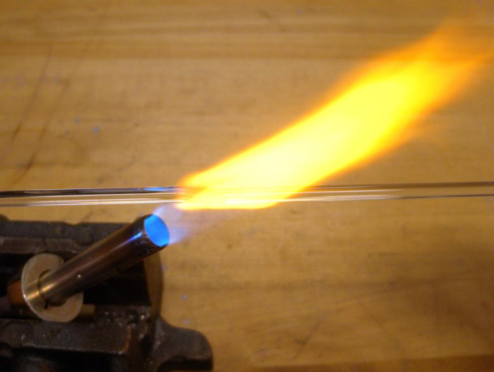
- Gently roll the rod back and forth with your fingers to evenly distribute the heat. Continue this process until the glass begins to deform and wilt (Figure 8-10). When the rod is noticeably deformed, remove it from the heat and immediately pull the ends so that a 1 mm filament is formed. Pass the middle of the filament back into the flame and pull again to make two 2 mm filaments.
- Step 3
Grip the thick end of one of the stirrers and carefully insert the 2 mm end into the flame at a 45-degree angle. The objective here is to form a glass ball at the end of the filament. Gradually feed the filament into the flame until the ball grows to approximately 3 to 4 mm in diameter (Figure 8-11).
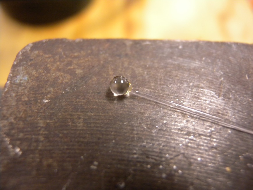
When you have achieved this size, remove the filament from the flame, turn off the torch, and hold the rod perpendicular to your work surface until the lens cools (Figure 8-12). Clip the lens off of the filament by using the wire strippers so that 1/2 in of filament is left attached to the lens.
Do not quench the lens in water because the thermal shock will shatter the glass.
- Step 4
- Use the countersink bit to recess the lens holder on both sides of the microscope body. Be careful that the 1 mm hole does not get widened. Position the lens into the lens holder and secure it in place with a drop of adhesive.
- Step 5
- Glue the mount onto the focus support. After the glue dries, insert the support into the microscope body and secure it in place with the focus screw. Sand the end of the dowel to produce a section approximately 30 degrees relative to the shaft. This will act as the specimen holder.
- Step 6
- Insert the dowel into the focus support and secure it in place with a rubber band. This band also helps prevent the dowel from rotating. Attach your specimen to the holder and hold the opposite end of the microscope to your eye. Look through the lens and focus the holder accordingly. This process works best if you backlight the specimen with a bright light source (Figure 8-13).
Makerspace Technology
Technology Education was designed to be a Makerspace. Most technical education classrooms are designed to function as workshops and can support projects starting with CAD design all the way to a completed prototype. By introducing these into the classroom, students can experience the full potential Makerspace technology has to offer:
Lab #4: Making a Water Rocket and Launcher
- Subject
- Technology
- Grade Level
- K–5
- Lab Type
- Technical Lab
- Estimated Class Time
- 1.5 Hours
- Objective
- Everybody loves rockets, especially elementary school students who marvel at the simple construction and launch of a water-propelled spacecraft model. Exposing students at this age to the fundamentals of physics will help them stay excited and potentially inspire them to become our future engineers and space explorers.
This project requires that safety glasses be worn throughout its entirety.
Overview
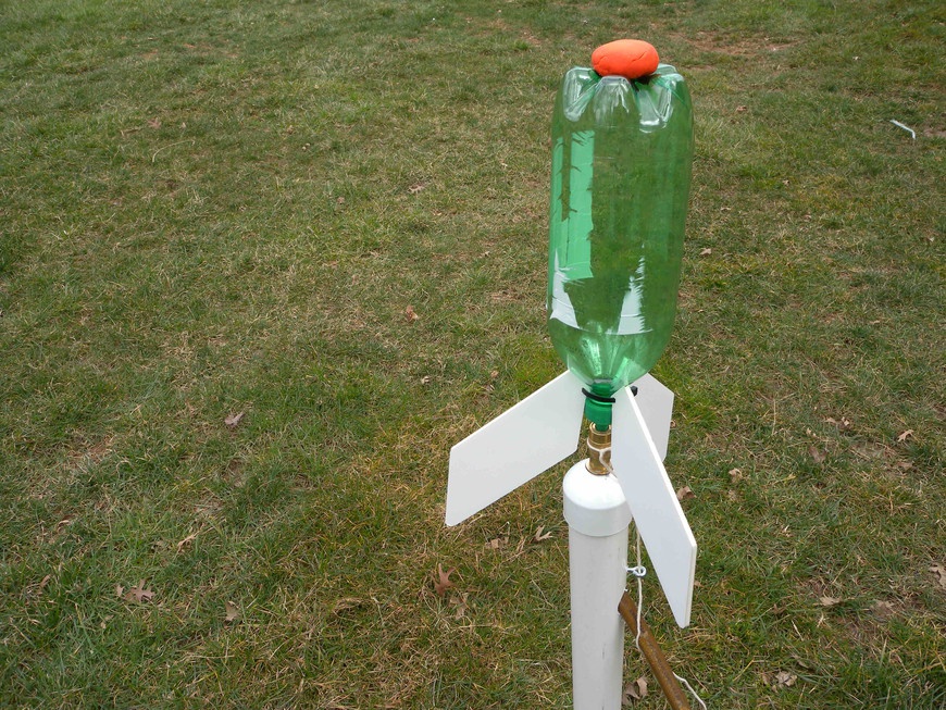
Newton taught us that for every action there is an equal and opposite reaction. Rockets use this very principle. Stored inside a commercial rocket is a large amount of fuel. This fuel is ignited, and the rapidly expanding gases exit the rocket with a tremendous amount of force, propelling the rocket in the opposite direction. Rather than have elementary school students handle volatile rocket fuels and dangerous propulsion systems, you can re-create the basic concepts behind rocket technology safely in the classroom (Figure 8-14).
Materials
You can find the files for this project at Thingiverse.com.
| Materials List | ||
Item | Quantity | Source |
Empty 2-liter bottle | 1 | Grocery store |
Pipe tape | 1 | Home improvement store |
24 in cable tie | 2 | Home improvement store |
12 × 24 in corrugated plastic sheet | 1 | Home improvement store |
2 × 24 in PVC pipe | 1 | Home improvement store |
2 in PVC pipe cap | 1 | Home improvement store |
Modeling clay | 1 | Craft store |
1/4-20 × 1/2 in eye bolt | 1 | Home improvement store |
1/4 in washer | 1 | Home improvement store |
1/4-20 nut | 1 | Home improvement store |
18 in string | 1 | Home improvement store |
1/4 in NPT quick-release female coupler with female thread | 1 | Home improvement store |
1/4 in NPT male plug with male thread | 1 | Home improvement store |
| Makerspace Tools and Equipment |
3D Printer |
1.5 in hole saw |
1/4 in drill bit |
Air compressor w/ hose |
Band saw |
Hand drill |
Packing tape |
Ruler |
Safety glasses |
Scissors |
Making the Launcher
- Step 1
- Start by drilling a 0.5 in diameter hole in the center of the PVC endcap. Wrap a small amount of thread-sealing tape around the threads of the male NPT plug. Pass the threaded portion of the plug through the hole and secure it with the quick release coupler. Attach the air hose to the male plug, and the top of the launcher is set.
- Step 2
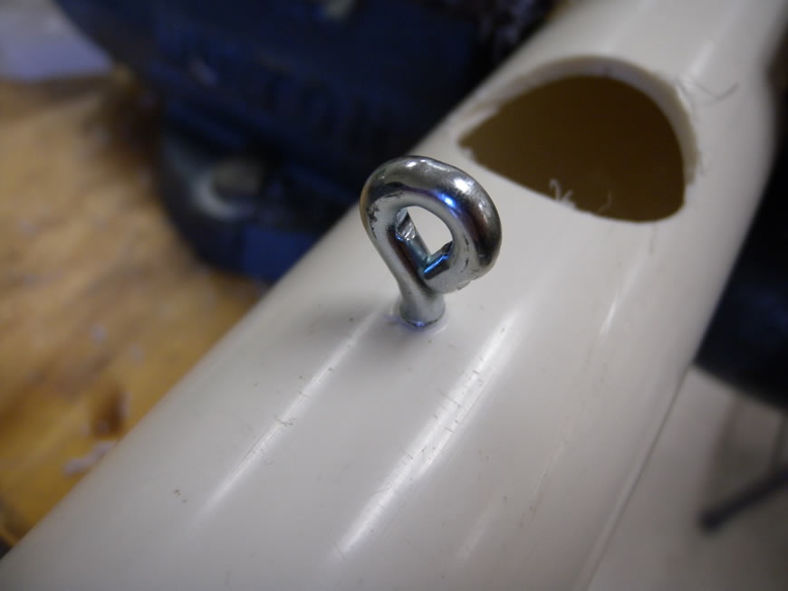
- Secure the PVC pipe in a vise and drill a 1.5 in diameter hole in the side of the pipe 6 in from the end by using a hole saw. Drill a 1/4 in hole 1 in above the 1.5 in hole. This hole will be used to secure the eye bolt (Figure 8-15). Taper the other end of the pipe by using the band saw. This taper will allow for the pipe to be driven into dirt, securing it in place during a launch.
- Step 3
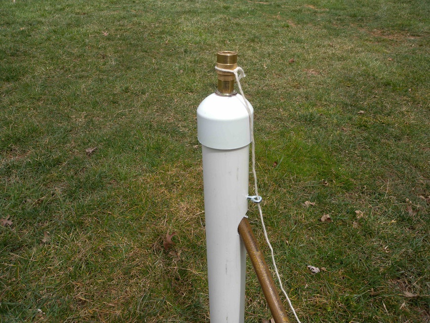
- Secure the eye bolt into the 1/4 in hole using a washer followed by a nut. This bolt is used to guide the launch cord. Pass the air hose through the 1.5 in hole and press on the endcap. Tie one end of the string around the body of the NPT coupler and pass it through the eye hole. Tug on the string to ensure that the coupler releases, and the launcher is complete (Figure 8-16)!
Making the Nozzle, Fins, and Nosecone
- Step 1
- Power up your 3D printer and start the control software. Import the BottleRocketNozzle.stl file and position onto the virtual build surface. The tapered end of the nozzle must face away from the build surface because the design contains overhangs. Begin by printing only one nozzle to ensure its quality and then print an array of the necessary quantity. This will save you the headache of finding out after an 8-hour print that your nozzles don’t fit.
- Step 2
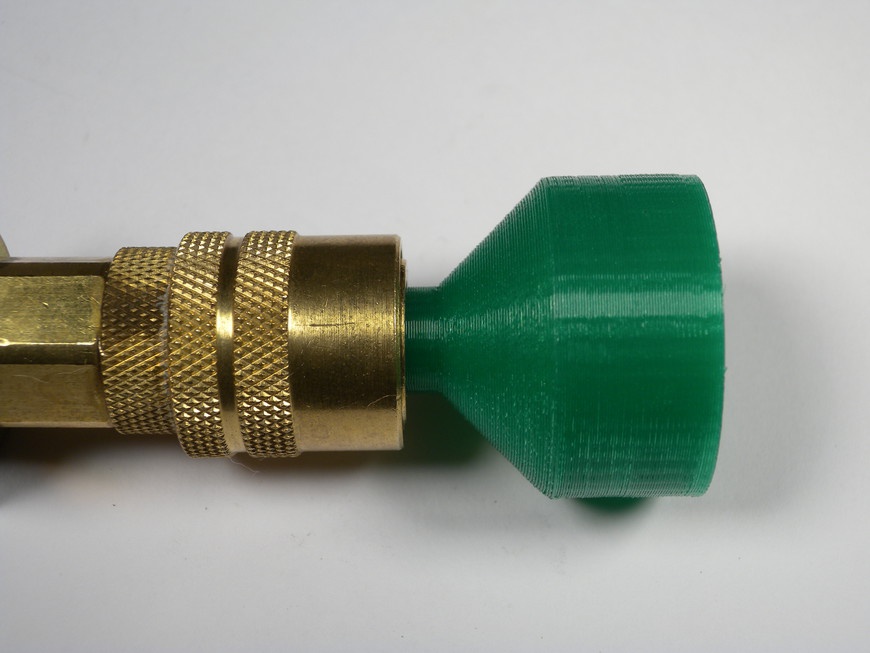
- Configure your build properties for 100 percent infill and send the layout to the printer. When the nozzle has finished printing, perform a fit check (Figure 8-17) on an unpressurized male quick connect coupler. The nozzle should be snug when seated and pop off easily when the release mechanism is activated.
- Step 3
- Pressure test your nozzle by inserting an O-ring into the nozzle and firmly fastening it to an empty bottle. Adjust your air supply to 40 PSI and connect the bottle. You should now hear minimal air leakage. If leakage is excessive, try scaling down the STL by 1 or 2 percent and try again until the problem is resolved.
- Step 4
- Open the bottleFin.dxf file in your 2D CAD software and create an array for the quantity of fins that you want to make. Typically, the rockets will use 3, but 4 or more might be desired for experimentation. Follow your laser cutter/engraver’s operating procedure for configuring the machine for cutting. Position the sheet of plywood on the cutting bed, send your drawing to the machine, power on the exhaust fan and air assist, and begin cutting.
Procedure
- Step 1
- Make sure all labels have been removed from the outside of the bottle and it is free of major scratches or cracks. Use a doorjam to draw a straight line down the side of the bottle with a marker. Wrap a string or piece of paper around the bottle and mark at the point of overlap. Fold the string into thirds and mark the points with a marker. Reattach the string to the bottle and transfer the two new marks. Again, use the doorjam to draw two new lines down the side of the bottle. You should now have three evenly spaced lines drawn on your bottle that will act as guides for aligning your fins.
- Step 2
Line up and attach one fin at a time to the previously marked positions using tape. Verify that the fins are positioned perpendicular to the bottle and that the tape is pressed firmly onto the surface of the fins and bottle. Repeat this step for the remaining fins.
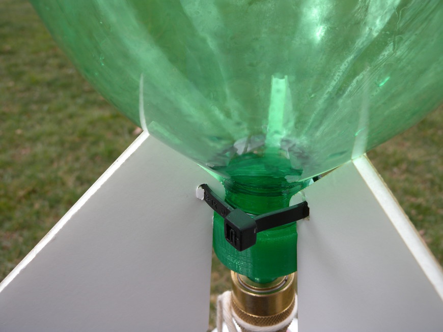
Hold the fins in place using the large cable ties (Figure 8-18). If you want, apply a small amount of hot glue along the interface between the fins and the bottle. Use a low temperature hot-glue gun because the high temperature guns will melt the bottle.
- Step 3
- Roll up the supplied clay into a ball, press it onto the base of the 2-liter bottle, and then secure it in place with a piece of tape. This clay will help to stabilize the flight of your rocket by moving its center of mass closer to the nose.
- Step 4
- Now that you have created your water rocket, it is time to decorate it. Use stickers, paint, and markers to personalize your rocket so it stands out from the rest. Finally, it’s time to launch.
- Step 5
- To launch your rocket, drive the launcher into the ground so that more than half of the 24 in PVC tube is underground. Remove the nozzle from the bottle and fill it 1/4 full with water. Reattach the nozzle and connect it to the launcher. Confirm that everyone is wearing safety glasses and is standing a safe distance away from the rocket and then, using the air compressor, pump up the rocket to no more then 40 PSI. Start your countdown: 4… 3… 2… 1… LAUNCH! Pull the string and watch the rocket fly!
Lab #5: Making a 3D Printed Robot
- Subject
- Technology
- Grade Level
- 6–8
- Lab Type
- Learning Tool
- Estimated Class Time
- 3+ Hours
- Objective
- Working with robotics is a marvelous way to expose students to multiple technology and engineering concepts operating in sequence. Robots require both software and hardware to function, and when they work together, various levels of “intelligence” can be simulated.
This project requires that safety glasses be worn throughout its entirety.
Overview
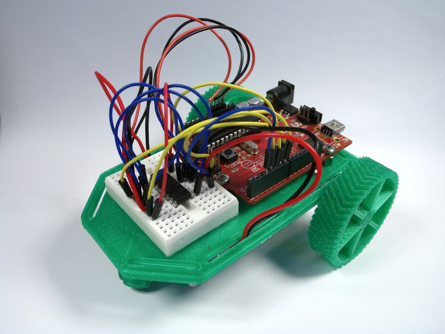
This lab bridges the gap between the virtual world of software and physical hardware. The students are required to implement the engineering design process to the design and construction of a simple two-wheeled robot (Figure 8-19) that is capable of autonomously completing tasks.
Materials
You can find the files for this project at Thingiverse.com.
| Materials List | ||
Item | Quantity | Source |
4-40 × 1/4 in machine screws | 4 | Home improvement store |
4-40 × 1/2 in machine screws | 2 | Home improvement store |
4-40 nut | 6 | Home improvement store |
#4 washer | 6 | Home improvement store |
4-40 standoff | 4 | Electronic supply store |
Tamiya 70168 gearbox kit | 1 | Hobby store |
Glass marble | 1 | Craft store |
L293D | 1 | Electronic supply store |
Pre-stripped breadboard jumper wire | 1 | Electronic supply store |
Male-to-male jumper wires | 1 | Electronic supply store |
2 ft Red and black 22-gauge wire | 1 | Electronic supply store |
Arduino | 1 | Electronic supply store |
Small breadboard | 1 | Electronic supply store |
9-Volt Battery | 1 | Electronic supply store |
9-Volt Battery snap connector | 1 | Electronic supply store |
| Makerspace Tools and Equipment |
3D Printer |
Band saw |
CAD software |
Solder |
Soldering iron |
Setup
- Step 1
- Open the robotPlate.stl, wheelRight.stl, and wheelLeft.stl files in your 3D printer’s control software and position it onto the virtual build surface. Process the build and send it to the 3D printer for fabrication. This file contains both the chassis and the wheels for the robot. While the chassis is being printed, assemble kits of electronic components for distribution to the students.
- Step 2
- Open the gearbox kit and solder the four motor wires to the motor’s terminals. Be careful not to apply too much heat because the motor is easily damaged. Disconnect the soldering iron when you’re done.
Procedure
- Step 1
- Assemble the gearbox per the manufacturer’s instructions. Position the four Arduino mounting nuts into the sockets on the chassis and attach the 4-40 standoffs. Remove the adhesive from the back of the breadboard and position it on the front of the robot chassis.
- Step 2
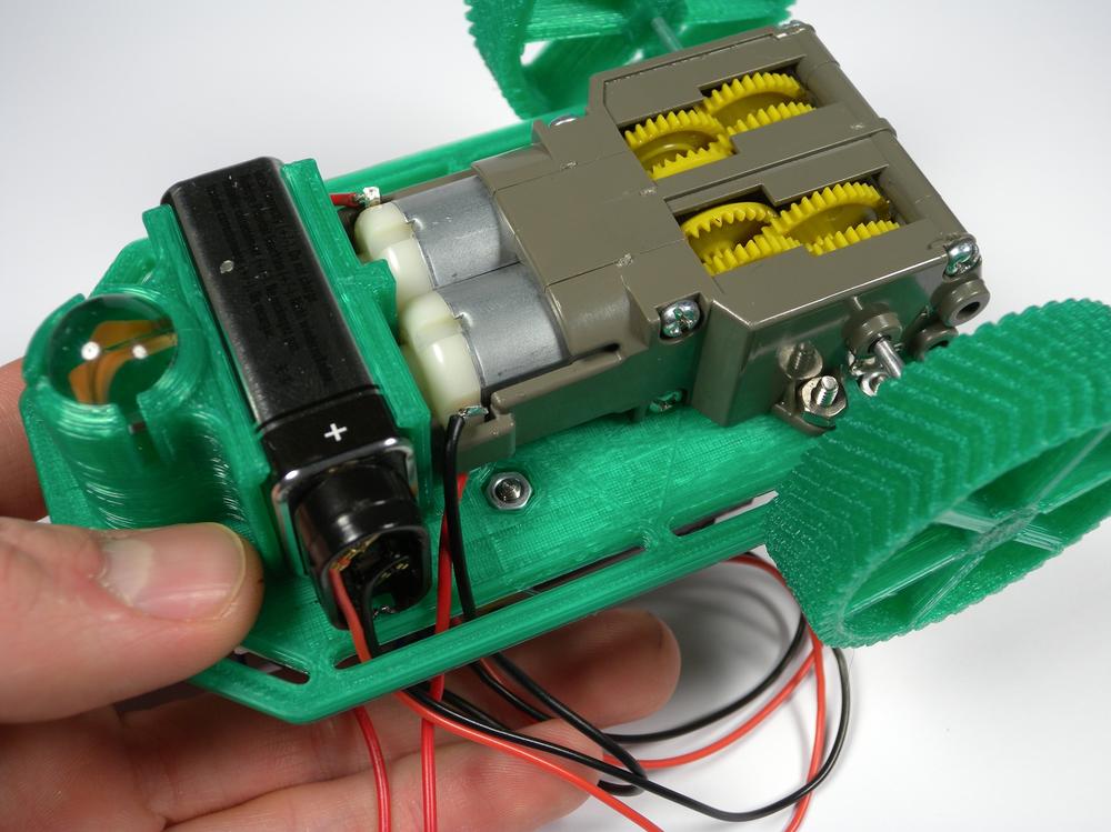
- Attach the gearbox to the chassis by using the two 1/2 in 4-40 bolts (Figure 8-20). Secure it in place with a washer and a nut. Attach the wheels to the gearbox and press the marble into the caster. Using the four 4-40 machine screws, attach the Arduino to the 4-40 standoffs. To avoid damaging the board, do not overtighten these screws.
- Step 3
Populate the breadboard by first seating the IC on the board and then securing the wires in place.
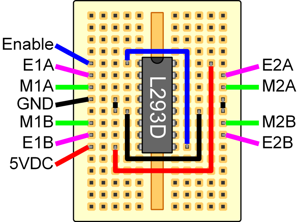
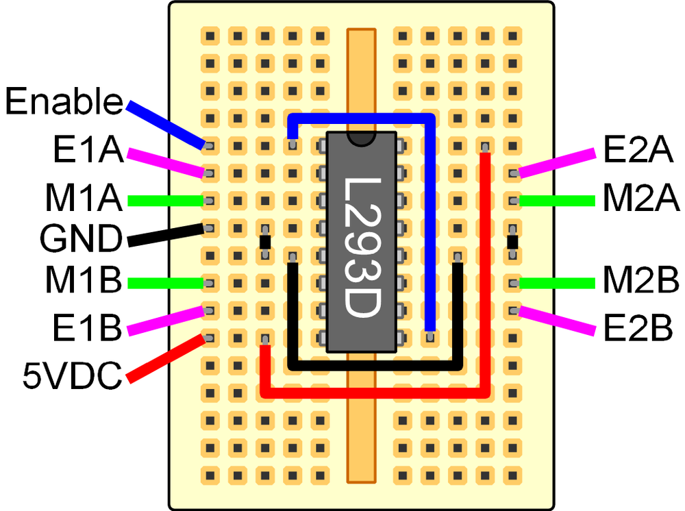
Use the male-to-male jumper wires to make connections back to the Arduino, following the color codes to ensure proper wiring. Use Figure 8-21 and Table 8-1 to connect the L293D to your Arduino.
| Motor controller | Arduino | Motor |
Enable | D3 | |
E1A | D4 | |
M1A | Motor 1 red | |
GND | GND | |
M1B | Motor 1 black | |
E1B | D5 | |
5 VDC | 5 VDC | |
E2A | D6 | |
M2A | Motor 2 black | |
M2B | Motor 2 red | |
E2B | D7 |
- Step 4
- Connect the robot to your computer and open the Arduino IDE. Copy Example 8-1 into your sketch and upload it to your robot.
- Step 5
- Snap the 9-volt battery into the holder and connect the snap connector. Your Arduino should now be powered and will run the robot test code. The robot should move forward and then backward when the test code is executed. If it does not, disconnect the battery and swap positions of M2A/M2B. This will reverse the direction of Motor 2.
Lab #6: Making a Brushless DC Motor
- Subject
- Technology
- Grade Level
- 6–8
- Lab Type
- Learning Tool
- Estimated Class Time
- 1.5 Hours
- Objective
- The electric motor has been around since the early 1800s and continues to power our world today. This lab focuses on developing an understanding of basic electromagnetism and the technology that governs the operation of brushless DC motors. This apparatus can be used as the basis for developing curriculum that focuses on the creation, application, and analysis of brushless DC motors.
This project requires that safety glasses be worn throughout its entirety.
Overview
Regardless of the type, DC electric motors contain two fundamental components: the rotor and the stator. The rotor is responsible for converting electric energy into rotational motion, and the stator acts to provide a mechanical coupling to the rotating armature. Although both brushed and brushless DC motors convert electrical energy into rotational energy, they contain only a few common components. A brushed DC motor is made up of the following:
- Armature Core
- The armature core is made up of ferrous plates that are bonded together to make a solid stack. This stack usually consists of three poles on which the armature winding is wound.
- Armature Winding
- The armature winding consists of insulated wire wound around the poles of a magnetic armature core. When energized, each pole becomes an electromagnet pulling the armature in line with the field magnet.
- Axle
- Supports the armature and commutator with either bushings or bearings, allowing them to spin freely.
- Brushes
- Consist of either carbon blocks or metal fingers that connect the DC power source to the commutator.
- Commutator
- Consists of metal plates equal to the number of electromagnets attached to the armature. These metal plates are connected in series with the each end of the coils and act as the electric bridge between the armature and the brushes.
- Field Magnet
- Consists of two or more permanent magnets that work in conjunction with the polarity of the armature to produce the force behind the rotational motor’s motion.
However, a brushless DC motor (Figure 8-22) only contains the following:
- Axle
- Supports the rotating rotor and is coupled to the stationary coil assembly with a series of bearings.
- Control Electronics
- Also known as an Electronic Speed Control, or ESC, the control electronics are responsible for switching on and off the driving coils, pulling the rotor in line with the electromagnetic field.
- Driving Coils
- Brushless DC motors typically have three or more driving coils. When energized, the coils pull the rotor in a series of controlled pulses.
- Permanent Magnet Rotor
- These are typically made of rare earth magnets and can be positioned internal or external to the motor. This “out-runner” and “in-runner” design makes sophisticated cooling methods possible and allows the motor to perform with greater than 90 percent efficiency.
Materials
You can find the files for this project at Thingiverse.com.
| Materials List | ||
Item | Quantity | Source |
1/8 in plywood Sheet | 1 | Home improvement store |
1/4-20 × 1 in bolt | 2 | Home improvement store |
1/4-20 nut | 2 | Home improvement store |
#4 washer | 2 | Home improvement store |
Breadboard | 1 | Electronic supply store |
10 ft 30-gauge coil wire | 2 | Electronic supply store |
470 Ohm resistor | 2 | Electronic supply store |
47k Ohm resistor | 2 | Electronic supply store |
220 uF capacitor | 2 | Electronic supply store |
TIP120 transistor | 2 | Electronic supply store |
2N2222 transistor | 2 | Electronic supply store |
Pre-stripped breadboard jumper wire | 1 | Electronic supply store |
6 in 22-gauge solid core wire | 4 | Electronic supply store |
9 V battery | 1 | Electronic supply store |
9 V battery snap connector | 1 | Electronic supply store |
1 in dia. doughnut magnets | 2 | Craft store |
1/8 in dia. drinking straw | 1 | Grocery store |
| Makerspace Tools and Equipment |
Laser engraver |
Wire strips |
Setup
- Step 1
- Open the brushlessDC.dxf file in your CAD software suite and create an array for the quantity of motors that you want to make. Follow your laser cutter’s operating procedure for configuring the machine for cutting. Position the sheet of plywood on the cutting bed, send your drawing to the machine, power on the exhaust fan and air assist, and begin cutting.
- Step 2
- Prepare kits containing the remaining components into sandwich bags for easy distribution to the students.
Procedure
- Step 1
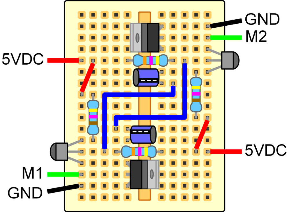
- Assemble the controller electronics following the provided diagram and the illustrations on the back of the circuit board (Figure 8-23). This circuit is a simple astable multivibrator.
- Step 2
- Use the wire snaps to cut two 10 ft lengths of coil wire. Pass one bolt through the motor’s vertical support and add a washer and nut to the threaded side. Leave 1/4 in of thread exposed under the screw’s head and tightly wrap all 10 ft of coil wire around the threads. Try to keep the coil wire as tight as possible. When complete, secure it in place with a drop of hot glue.
Classroom floor tiles are often 1 × 1 ft and make for a quick measurement tool.
- Step 3
- Assemble the rotor by sliding the magnet mounts onto the center of the axle and glue it in place with a drop of super glue. Add the magnets so that the poles align and secure them in place with a drop of super glue. Place an 1/8 in piece of drinking straw into the axle mounts. This acts as a bearing surface, allowing the axle to spin more freely (Figure 8-24).
- Step 4
- Test fit the motor structure, and if you’re satisfied, glue together the pieces by using wood glue; allow to dry completely. Check that the coils are facing toward the inside of the structure and that the rotor spins freely. Slide the two wooden washers over the ends of the axle and glue them in place with super glue. These prevent the rotor from “wandering” while in motion. Verify that the rotor spins freely after gluing.
- Step 5
- Attach the coil wires to the control board by carefully sanding away the insulation at the ends of the wire, securing them into the breadboard. If the coil wires do not fit nicely into the breadboard, they can be soldered to short 22-gauge jumper wires that better fit in a breadboard. Energize the control board by attaching the 9-volt battery, and the rotor should begin to shake. Give the axle a quick spin with your fingers to start the motor. If it doesn’t work, try switching the polarity on one coil and ensure that your circuitry was assembled correctly.
Makerspace Engineering
Engineering bridges the gap between the concepts covered in Math and the structures constructed in Technology Education. These principles can be demonstrated and validated by using Makerspace technology. The following labs are designed to develop problem-solving skills through the design, construction, and analysis of engineering concepts:
Lab #7: Making a Sail Car
This project requires that safety glasses be worn throughout its entirety.
Overview
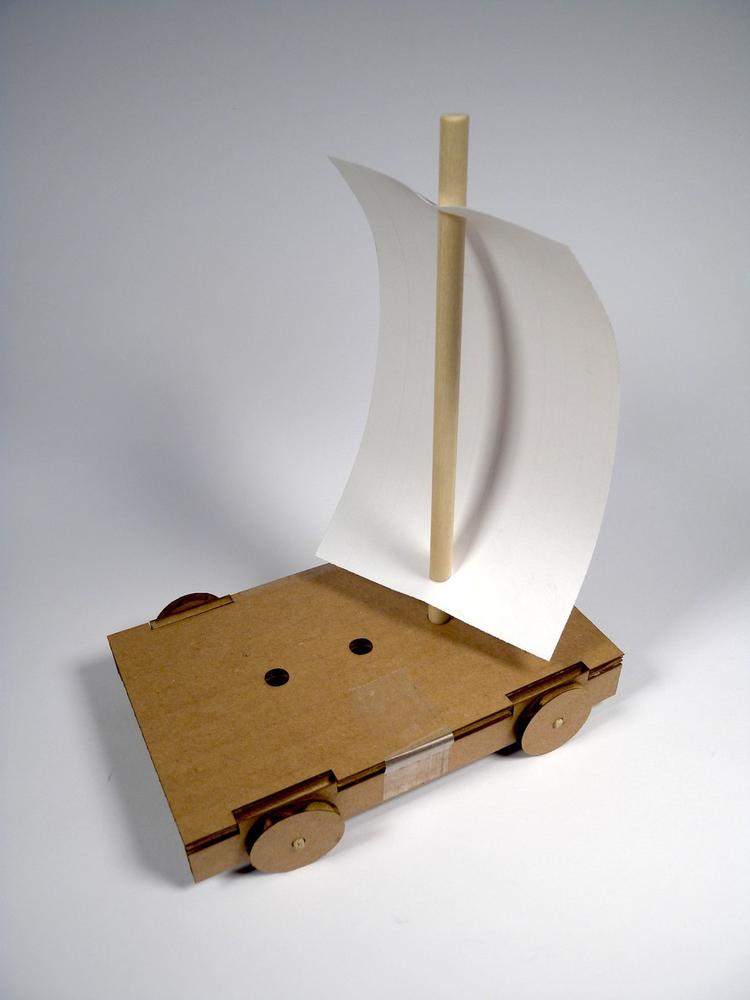
Problem solving is the most important skill a student can have. They can use it to conceptualize the solution to a task prior to any research, bookwork, or prototyping. It also gives them insight as to whether their research, bookwork, or prototype is headed in the right direction. This lab is designed to expose elementary school students to the trials faced when designing and constructing a wind-powered car (Figure 8-25). After the kit has been assembled, the students should be given the opportunity to test and redesign their solutions for best results.
Materials
You can find the files for this project at Thingiverse.com.
| Materials List | ||
Item | Quantity | Source |
1/8 × 3.5 in wooden dowel | 1 | Craft store |
1/8 × 3 in drinking straw | 1 | Grocery store |
1/4 × 5 in wooden dowel | 1 | Craft store |
3 × 5 in notecard | 1 | Craft store |
Notebook paper | 1 | Craft store |
Tape | 1 | Craft store |
Cardboard | 1 | Craft store |
| Makerspace Tools and Equipment |
Box fan |
Hand saw |
Hole punch |
Laser engraver |
Safety glasses |
Setup
- Step 1
- Open the windCar.dxf file in your CAD software suite and create an array for the quantity of cars that you want to make. Remember to include one body and four wheels for each car. Follow your laser cutter’s operating procedure for configuring the machine for cutting. Position the sheet of cardboard on the cutting bed, send your drawing to the machine, power on the exhaust fan and air assist, and begin cutting.
- Step 2
- While the cars are being cut on the laser, prepare the axles and straws by cutting them to length using your wire strippers, and cut the 1/4 in dowel using a saw. Gently sand the ends of the dowels to prevent splinters. Punch two holes in the sheet of paper 3 in apart by using a hole punch. These holes will be used to hold the sail in place. When the laser cutting has finished, assemble kits of parts in sandwich bags for distribution to the students.
Procedure
- Step 1
- Begin by attaching the two car sides onto the body by using small pieces of tape or glue. Pass the two straw pieces through the mounts on either side of the car and then secure in place with a piece of tape. Be careful not to bend the straws; this will prevent the wheels from turning.
- Step 2
- Assemble the mast by passing the 1/4 in dowel through the holes in the card and into one of the positioning holes. These holes will be used to determine the best position of the mast through testing. Secure the mast in place with a piece of tape.
- Step 3
- Place the wind car in front of the fan and turn it on. The car should now travel across the floor using the power of the breeze created by the fan. The performance of your wind car can be improved by changing the design of the sail. Use extra sheets of paper, a hole punch, and scissors to design new types of sails. Try to make the fastest possible car. Which design worked best?
Lab #8: Making a Wind Turbine
- Subject
- Engineering
- Grade Level
- 6–8
- Lab Type
- Technical Lab
- Estimated Class Time
- 4+ Hours
- Objective
- Generating electrical energy from renewable sources requires a lot of engineering and imagination. One of the simplest forms of energy that we can harvest is that of the wind. Whether installed off-shore, on mountain tops, or on open plains, wind turbines provide a low impact and effective method for converting wind energy into electrical.
This project requires that safety glasses be worn throughout its entirety.
Overview
Wind turbines are elegant machines that convert power from the wind into electrical energy. This is accomplished when the wind passes over the surface of the turbine’s blades generating lift and rotational force. The rotating blades are connected to a generator that creates electrical energy when spun.
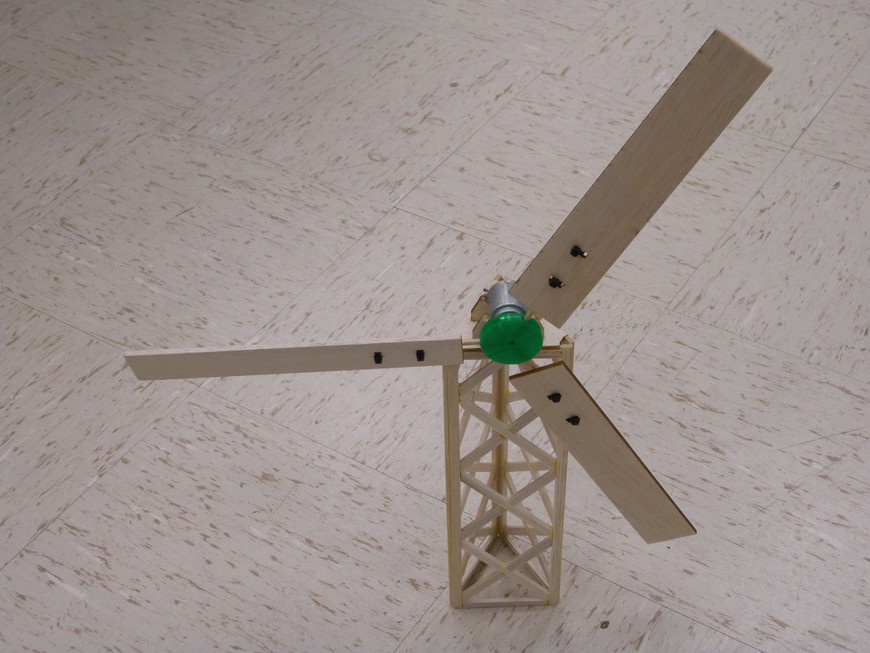
This lab utilizes inexpensive materials to create a small, low-power, horizontal axis wind turbine (Figure 8-26). You can measure the efficiency of the turbine by using a multimeter and can alter it by changing the blade’s angle of attack as well as refining blade design.
Materials
You can find the files for this project at Thingiverse.com.
| Materials List | ||
Item | Quantity | Source |
1/8 × 1/4 in × 36 in balsa strips | 4 | Craft store |
1/8 × 3 in × 12 in balsa sheet | 1 | Craft store |
1/8 × 3 in booden dowel | 3 | Home improvement store |
DC electric motor with 2 mm shaft | 1 | Hobby store |
| Makerspace Tools and Equipment |
Laser engraver |
3D printer |
Multimeter |
Box fan |
Vise |
Hot-glue gun with glue |
Making the Blade Hub
- Step 1
- Open the WindTurbineHub.stl file in your 3D printer’s control software and position it onto the virtual build surface. Process the build and send it to the 3D printer for fabrication. Using a low build quality is acceptable here because it will decrease your build time. Assemble kits of parts for distribution to the students while the hubs are printing.
Making the Tower
- Step 1
- Print out a full scale copy of the turbine.dxf tower template and tape it to your work surface. Tape an overhead projector transparency over the template to prevent the glue from sticking.
- Step 2
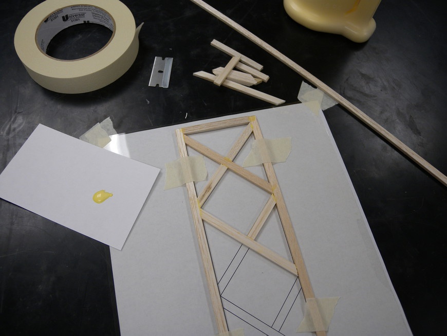
- Use a razor to carefully align and cut out all of the beams and cross members as shown on the template. Tape down the beams between the joints, apply a small amount of glue to the ends of the cross members, and then glue them into place. After the glue has dried, repeat this process two more times. Glue the three tower sections together to form your wind turbine’s tower (Figure 8-27). After the tower is dry, glue it to the hardboard base and attach the motor mount.
- Step 3
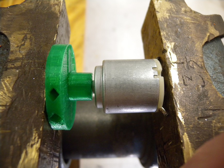
- Using a small vise, press the hub onto the motor (Figure 8-28). Do not try to bore out the hub; this will prevent it from coupling to the motor’s drive shaft. Secure the motor to the top of the turbine by using a small amount of hot glue.
Making the Blades
- Step 1
- Open the turbine.dxf file in your CAD software suite and create an array of the number of blades that you want to make. Follow your laser cutter’s operating procedure for configuring the machine for cutting. Position the 1/8 in balsa sheet on the bed. Send your drawing to the machine, power on the exhaust fan and air assist, and begin cutting.
- Step 2
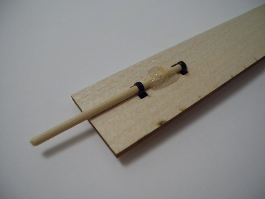
- Attach each blade to the end of the dowels and secure them in place with two cable ties. When you have the blade position set, glue the blade to the dowel by using a small amount of wood glue. Connect the blades to their respective holes on the hub. If the blade twists on the wooden dowel, secure it in place with a small amount of hot glue (Figure 8-29). This hub is designed for 3 or 4 blades and will distribute the blades evenly. Give your turbine a gentle spin and see if it works.
Investigation
Wind turbines operate by converting the flow of air to a rotational force that drives a generator. This is accomplished through the research and design of blades that harness as much wind energy as possible while producing the least amount of resistance.
- Measuring Output
Connect your multimeter’s negative (black) lead to one test lead and the positive (red) lead to the other test lead. Configure your multimeter to measure VDC and adjust the scale accordingly. If the numbers on the screen are negative, your leads are connected backward.
- What happens to the voltage as the turbine is moved closer to the fan?
- What happens to the voltage as it is moved farther away?
- Adjusting Angle of Attack
The angle of attack is the angle at which the blades are positioned relative to the path of the wind.
- How does a higher angle of attack affect rotation?
- How does a lower angle of attack affect rotation?
- Modifying the Blades
Lab #9: Making a Hot-Air Balloon
- Subject
- Engineering
- Grade Level
- 9–12
- Lab Type
- Technical Lab
- Estimated Class Time
- 3+ Hours
- Objective
- This lab is designed to expose students to the effect of temperature on the density of a gas by constructing and flying a tissue-paper hot-air balloon. Through investigation, the students will make the correlation between volume, temperature, and lifting force.
This project requires that safety glasses be worn throughout its entirety.
Overview
Hot-air balloon technology has been around since the late 1700s and still amazes onlookers today. The fundamental design of a hot-air balloon is based around the Ideal Gas Law. This law states that the pressure and volume of a gas directly relates to its temperature and moles of gas:
PV = nRT
Where P equals the gas’s pressure in Pa, V is the volume in m3, n is the number of moles of gas, R is the ideal gas constant of 287.058 J/(kg × K), and T is the temperature of the gas in K. You can write this equation to illustrate the effect of temperature on the density of a gas:
ρ = P / (R × T)
Where ρ represents the gas’s density in kg/m3, P is the pressure in Pa, R is the ideal gas constant of 287.058 J/(kg × K) and T is temperature in K.
You can use this equation to express the quantity of mass a hot-air balloon can lift based on the volume of the balloon and its temperature. This is known as the balloon’s buoyant force. This force can be calculated by accounting for the difference in density of the air inside and outside of the balloon and its weight. So, will it float?
Ft = (ρa – ρb) × V × g
Where Ft represents the quantity of force generated by your balloon, ρa is the density of the air outside of the balloon in kg/m3, ρb is the density of the air inside of the balloon in kg/m3, V is the volume in m3, and g is the gravitational constant of 9.81 N/kg.
You can use these equations to either determine the quantity of mass the balloon can lift, or you can re-tailor them to determine the size of the balloon required to lift a specific mass.
The body of a hot-air balloon is made up of a series of strips of fabric called gores. The gores are stitched together and the final shape of the balloon is revealed. Because the hot gas inside of the balloon is compressed by the surrounding cooler gases, a shape in the form of a light bulb is optimal. This shape allows for a large pocket of gas to reside at the top of the balloon and provides for a more stable design (Figure 8-30).
Materials
You can find the files for this project at Thingiverse.com.
| Materials List | ||
Item | Quantity | Source |
6 × 24 in stove pipe | 1 | Home improvement store |
8 × 24 in stove pipe | 1 | Home improvement store |
8-32 × 1.5 in bolt | 6 | Home improvement store |
8-32 nuts | 12 | Home improvement store |
8-32 washers | 6 | Home improvement store |
1/4-20 × 1/2 in bolts | 6 | Home improvement store |
1/4-20 nuts | 6 | Home improvement store |
1/4-20 washers | 6 | Home improvement store |
12 in shelving brackets | 3 | Home improvement store |
Camping stove w/ fuel | 1 | Sporting goods store |
20 × 30 in tissue paper sheet | 12 | Craft store |
1/8 × 32 in aluminum rod | 1 | Home improvement store |
3/16 in heat-shrink tubing | 1 | Electronic supply store |
| Makerspace Tools and Equipment |
Glue sticks |
Safety glasses |
Sheet metal punch |
String |
Making the Balloon Launcher
- Step 1
- Wrap a piece of string around the 8 in stove pipe and make a mark it at the overlap. Fold the string into three equal lengths and make marks that divide the string into three sections. Wrap the string back around the stove pipe and make three marks approximately 1 inch from the end of the pipe. Repeat this process for the 6 in pipe. Use a door jam as a straightedge and draw another line 1 inch in on the opposite end of the pipe. Repeat this process for each line on both pipes.
- Step 2
- Measure in 1 in from the end of the pipes and make a cross on your previously marked lines. This will act as a guide for your punch. Equip your sheet metal punch with a 3/16 in punch set and punch holes at each intersection. Repeat this process by aligning the angle brackets along the bottom, spaced evenly. Mark the bracket’s mounting hole positions on the 8 in pipe and punch holes using a 1/4 in punch. Using the 1/4-20 nuts and bolts, mount the 3 shelving brackets to their corresponding holes on the 8 in stove pipe. Secure the brackets to the pipe by using 1/4-20 bolts, nuts, and washers.
- Step 3
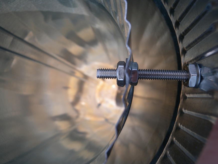
- Position the 6 in pipe inside the 8 in pipe and line up the top and bottom holes. Pass each 6-32 bolt through the 8 in pipe hole first, add a washer and nut, and then pass the end of the screw through the hole in the 6 in pipe. This configuration allows you to suspend the hot 6 in pipe inside of the 8 in pipe thus preventing injury to the students and catching the balloon on fire (Figure 8-31).
- Step 4
Tighten all six fasteners to the 8 in pipe and add the remaining washers and nuts to the ends of the screws inside the 6 in pipe. Gently tighten the nuts inside the 6 in pipe until they are just tight. If you over tighten them, the walls of the pipe will distort and potentially crack. Test the stability of your launcher by placing it on a flat surface.
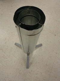
The base of the launcher (Figure 8-32) should be approximately 2 in above the ground and the pipes should be perpendicular with the floor.
Making the Balloon
- Step 1
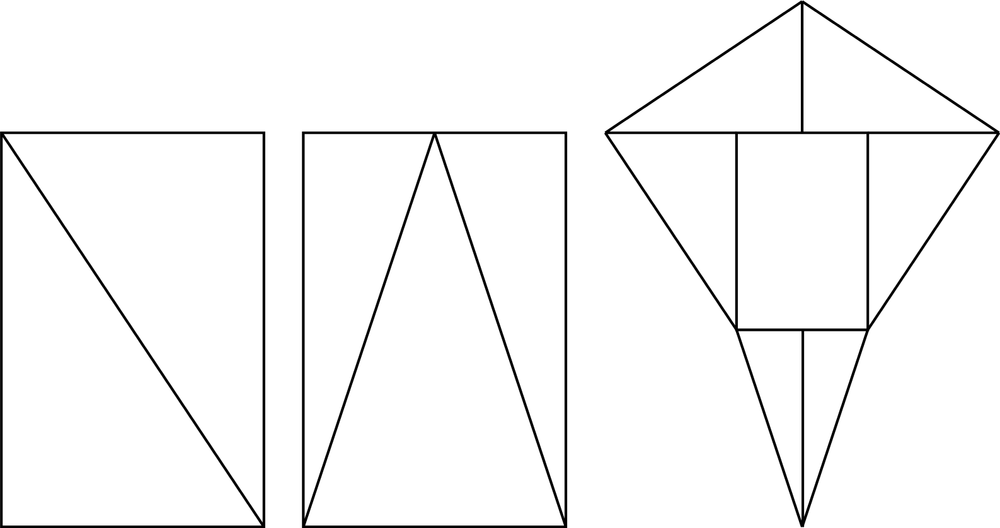
- Using a large format printer, or multiple sheets of paper, print out full-sized copies of the tissueBalloon.dxf gore template (Figure 8-33). Carefully draw a line around the perimeter of the gore template with an 0.5 in offset and cut out the template when complete. This offset accommodates the added material needed to glue the gores together.
- Step 2
- Determine how many pieces of tissue paper are needed to assemble one gore and glue them together with a glue stick, end to end, and with a 0.5 in overlap. After the glue dries, neatly stack your tissue paper and place the gore template on top. Use two binder clips to secure the tissue paper and gore template in place. Slowly cut along the edge of the gore template and through all of the sheets of tissue paper. The result should be a bundle of gores with the template on top.
- Step 3
- One at a time, run a bead of glue down the edge of the gore and glue it to another. Repeat this process until all of the gores have been attached. Cut out a small circle of tissue paper and adhere it to the top of the balloon. This helps to prevent hot air from leaking through the opening at the top.
- Step 4
- Create a 9 in circle from your aluminum rod and cover the junction with a 1 in piece of heat-shrink tubing. Shrink the tubing in place with the heat gun. Attach the aluminum ring to the opening at the base of your balloon, positioning the ring inside the base and folding tissue paper around it. Glue the tissue paper in place with your glue stick. Let your balloon dry for about 30 minutes. During this time, carefully examine the seams and look for potential leaks. If you find one, smear some glue from the glue stick onto your finger and use it to close the hole.
- Step 5
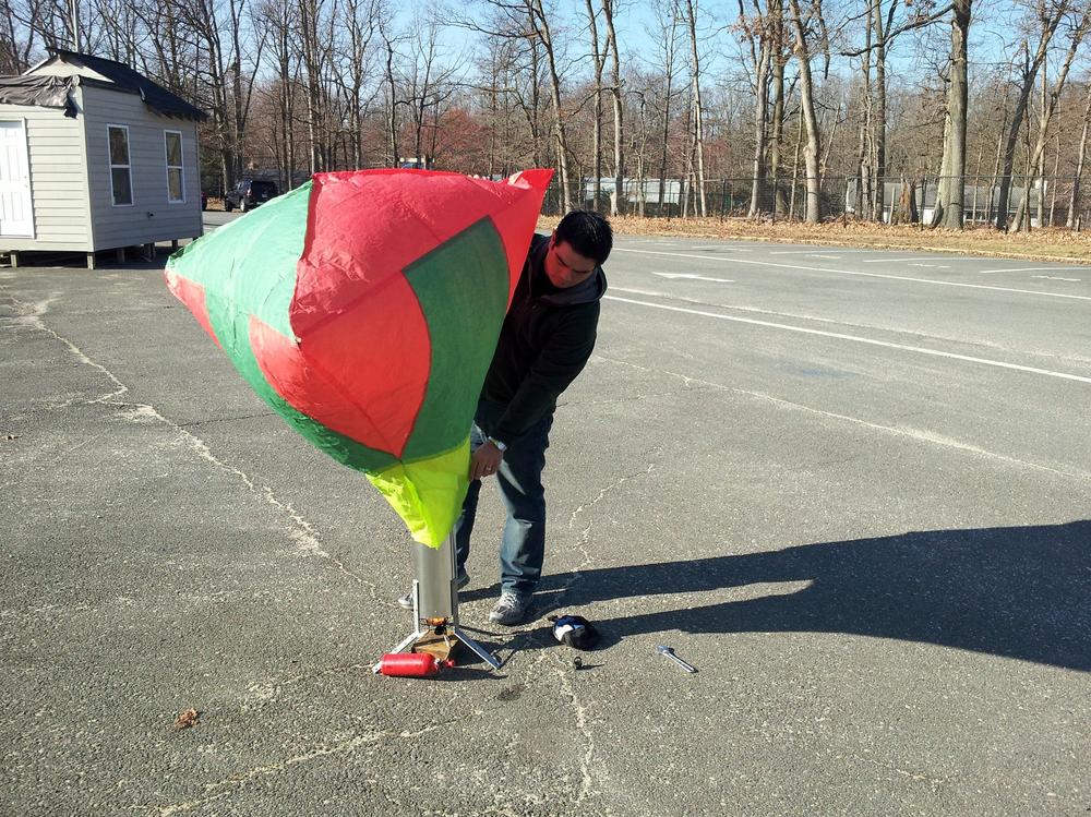
- When the balloon is dry, it is ready for flight (Figure 8-34). With the help of your instructor, assemble the launcher and fire up the burner. Carefully position the balloon over the launcher, and as soon as the balloon is full of hot air, let it fly!
Investigation
Because hot-air balloons produce lift by enclosing a gas with less density than the surrounding air, you can calculate the quantity of lift. You can use this calculation to determine how much mass the balloon can lift given the difference in gas temperature inside and outside of the balloon.
- Calculating Lift
Use the formulas provided at the beginning of this lab to determine how much mass your balloon should lift.
- How much mass can the balloon lift if the outside air temperature is 40°F and the temperature of the air inside the balloon is 100°F?
- How big would the balloon need to be to lift you?
- Measuring Lift
Makerspace Art
The utilization of Makerspace technology in the art classroom is a natural fit. Where technology education and engineering work to bring theoretical concepts into reality, art works to improve their design and appeal. Using these tools in art helps to bring new mediums into the classroom and exposes the students to the alternative uses of the technology:
Lab #10: Making a Silhouette
- Subject
- Art
- Grade Level
- K–5
- Lab Type
- Activity
- Estimated Class Time
- 45 Minutes
- Objective
- Making the connection between the virtual world of computers and the real world is an important recurring concept. This lab is designed to give students the opportunity to physically create a personal silhouette using photography, digital art, and a laser cutter.
Overview
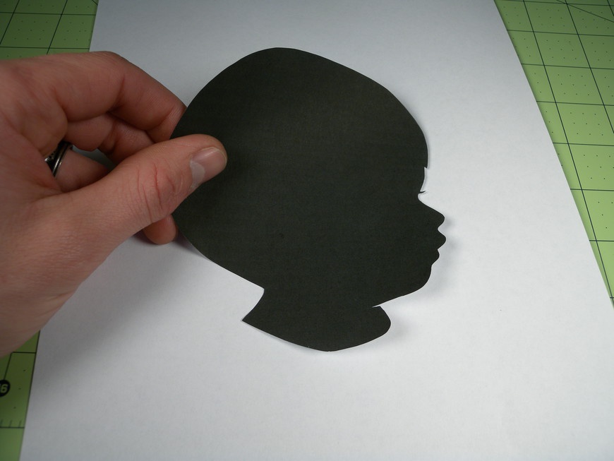
A silhouette (Figure 8-35) is a shadow representation of an object that conveys both depth and emotion. This simple artform is commonly used to capture portraits using inexpensive materials. With the help of Makerspace technology, you can create an effective silhouette from a single digital photograph.
Materials
| Materials List | ||
Item | Quantity | Source |
8.5 × 11 in black construction paper | 1 | Craft store |
8.5 × 11 in white printer paper | 1 | Craft store |
Glue stick | 1 | Craft store |
| Makerspace Tools and Equipment |
Digital camera |
Laser engraver |
Photo editing software or CAD |
Tripod |
Setup
- Step 1
- Create a monotone backdrop for the student photos by using a white sheet or blank wall. Position a chair in front of the backdrop and place a strip of tape on the floor indicating the position of the student’s feet. Set up the camera and tripod approximately 6 ft away from the chair and adjust the camera until it is level with the average height of a student’s head.
- Step 2
Configure the camera to use the countdown timer. This way, the student can take the picture while also eliminating the chance of a blurry picture due to camera movement. Separate your students into teams of two. One student will be in charge of taking the other’s photo, and vice versa. Have the first student sit on the chair so that her silhouette is visible in the viewfinder or on the LCD. Let the student’s partner take the picture and continue until everyone is photographed.
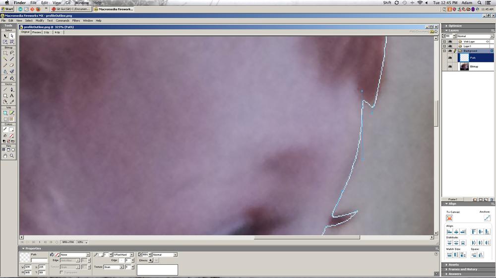
Be sure to use a high-contrast backdrop (Figure 8-36). This will help the students when they trace around their face.
Procedure
- Step 1
- Open the defaultTemplate.dxf file from Project: Creating a Default Template, into your CAD software and import the student’s photograph into the vector-drawing software of your choice. Select the Spline tool. This tool usually looks like a squiggled line. Guide the students through the process of clicking the mouse around the outline of their face. The spline tool automatically creates a curved line through the points created by the mouse clicks. If the student wants to edit his spline, he can simply move the points or nodes after he has finished the initial spline. Delete the student’s photograph from the layout and position the silhouette spline into the cutting area.
- Step 2
- Follow your laser cutter’s operating procedure for configuring the machine for cutting. Position the black construction paper on the cutting bed, send your drawing to the machine, power on the exhaust fan and air assist, and begin cutting. Hand out the silhouette cutouts to the students along with a sheet of white paper and a glue stick, and then have them glue their silhouette’s to the paper.
Lab #11: Making a Mold and Casting a Part
- Subject
- Art
- Grade Level
- 6–8
- Lab Type
- Activity
- Estimated Class Time
- 1.5 Hours
- Objective
- A significant amount of the world around us is the product of a molding process. From resins to plastics, molding makes it possible for us to quickly and inexpensively create multiple copies of an existing three-dimensional object. Understanding the fundamentals of this process helps to develop an appreciation for consumer objects and how they are made.
This project requires that safety glasses be worn throughout its entirety.
Overview
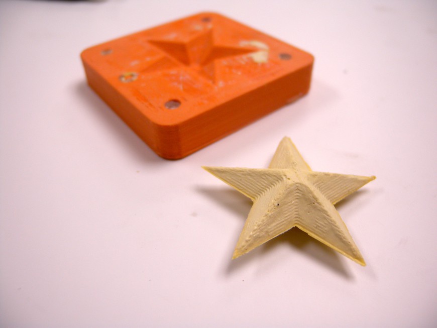
Part molding is used by industry to rapidly produce copies of an object. You can replicate this relatively simple process by using only a few materials, yielding results that are very close to perfect (Figure 8-37).
Materials
You can find the files for this project at Thingiverse.com.
| Materials List | ||
Item | Quantity | Source |
Plaster of paris or equivalent | 1 | Home improvement store |
Petroleum jelly | 1 | Grocery store |
| Makerspace Tools and Equipment |
3D printer |
Gloves |
Masking tape |
Safety glasses |
Sandpaper |
Procedure
- Step 1
- Create a small shape that you would like to cast via the solid-modeling software of your choice. Save the file and open the moldBlankBottom.stl and moldBlankTop.stl files. Create an assembly with the mold bottom and your part. Position the bottom half of your part within the mold bottom and use the Subtract tool to remove the shape’s volume from the mold. Repeat the procedure for the mold top using the top half of your part. Save your work and export the files as .stl.
- Step 2
- Using a sheet of 400-grit sandpaper, gently sand flat the mold faces so that they seal tightly. Lightly coat the surface of the mold with petroleum jelly and rub clean with a paper towel. This helps the casting to separate from the mold. Align the two mold pieces together and secure with masking tape. For larger or misshapen molds, use threaded fasteners to clamp the two pieces.
- Step 3
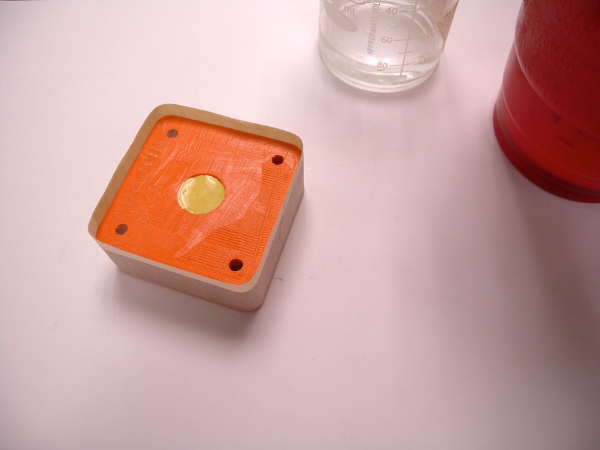
- Mix up a small batch of plaster and pour it into the mold (Figure 8-38). Gently tap the mold on your work surface to eliminate as many bubbles as possible. Let the mold rest for the plaster’s required set time.
Lab #12: Making a Printing Press
- Subject
- Art
- Grade Level
- 9–12
- Lab Type
- Learning Tool
- Estimated Class Time
- 1.5+ Hours
- Objective
- Printing today continues to be as relevant as it was during the time of Gutenberg and his press. From books to t-shirts, printing is an artform that allows for the rapid reproduction of artwork onto almost any medium.
Overview
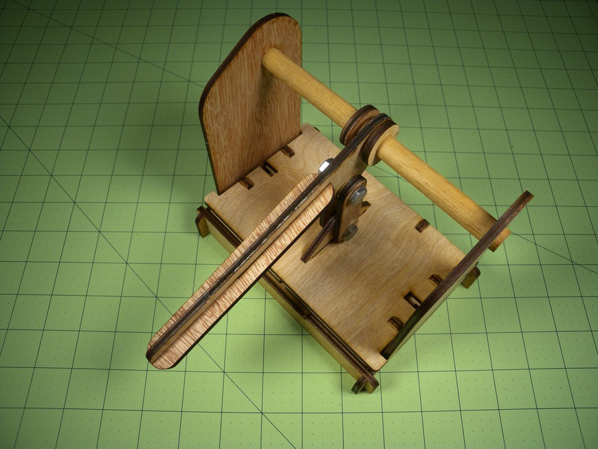
This lab is designed to expose students to the mechanics of paper printing through the construction of a single stamp printing press and corresponding stamp (Figure 8-39). The resulting press is capable of accepting a custom-made stamp cartridge and transferring its image to a 3 × 5 in piece of paper.
Materials
You can find the files for this project at Thingiverse.com.
| Materials List | ||
Item | Quantity | Source |
1/4 in rubber sheet | 1 | Craft store |
1/8 in plywood sheet | 1 | Home improvement store |
1/4-20 × 1-1/4 in bolt | 2 | Home improvement store |
1/4-20 nut | 2 | Home improvement store |
1/4 in washer | 4 | Home improvement store |
3 × 5 in blank cardstock | 10 | Craft store |
Colored roll on ink | 1 | Craft store |
| Makerspace Tools and Equipment |
Laser engraver |
Making the Stamp
- Step 1
- Open the stamp.dxf template in your CAD software and insert the desired image or text inside the designated area. Remember to invert any text because it will print the mirror image of what you see on the screen. Some print drivers can do this for you automatically, and you can use this in lieu of inverting the text in the CAD software.
- Step 2
- Follow your laser cutter’s operating procedure for configuring the machine for engraving and cutting stamps. Position the stamp material on the bed, send your drawing to the machine, power on the exhaust fan and air assist, and begin engraving. After engraving, the machine will cut the outline.
Making the Press
- Step 1
- Open the press.dxf file in your CAD software suite and create an array of the number of presses that you want to make. Follow your laser cutter’s operating procedure for configuring the machine for cutting. Send your drawing to the machine, power on the exhaust fan and air assist, and begin cutting.
- Step 2
- Construct the bed by gluing the reference pins in place with a small amount of glue. When dry, assemble the press by gluing the two sides to the base. Slide on the front and back cross members to complete the primary structure. The notches are designed to lock the cross members in place when fully assembled.
- Step 3
- Assemble the press plate by gluing the reference pins in place and attaching the pivot mount. When dry, attach the two press arm connecting rods to the mount by sliding a washer and then a bolt through the assembly. Lightly secure the bolt with another washer and nut.
- Step 4
- Slide the 1/2 in dowel through one of the sides and add a wooden washer. Slide the press arm over the dowel and add another washer. Secure the dowel in place by gluing the two last wooden washers over the ends of the dowels so that it turns freely yet does not slide side to side. Attach the connecting rods to the press arm with the remaining bolt, washers, and nut.
- Step 5
- Assemble the stamp cartridge by gluing the reference pins in place. When dry, position the rubber stamp onto the plate and slide the assembly into the press. The reference pins should properly align the stamp to the press plate. Lower the press until it just touches the surface of the stamp. Make any adjustments to the height of the spring mounts to make the bed as level as possible.
- Step 6
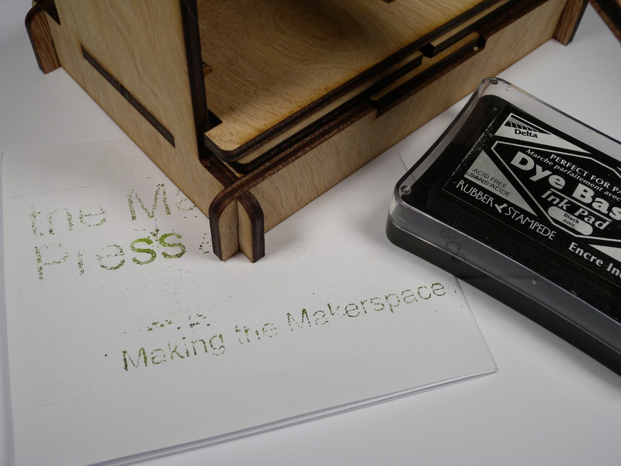
- Raise the press and remove the cartridge. Slide a 3 × 5 in card into the press plate holder and apply ink to the stamp surface. Place the cartridge back in the press and compress to transfer the image (Figure 8-40).
Makerspace Math
The use of Makerspace technology in the math classroom opens the door to a wide range of demonstration and student interaction possibilities. You can use this technology, which is commonly thought to exist in more hands-on classrooms, to reinforce math’s theoretical concepts:
Lab #13: Making Plane Shapes
- Subject
- Math
- Grade Level
- K–5
- Lab Type
- Learning Tool
- Estimated Class Time
- 45 Minutes
- Objective
- This lab is designed to expose students to the design and creation of plane shapes by using a simple yet effective pegboard device. In addition, students can use the device to explore the different ways in which they can create basic shapes. It also gives them the opportunity to self pace through the process.
Overview
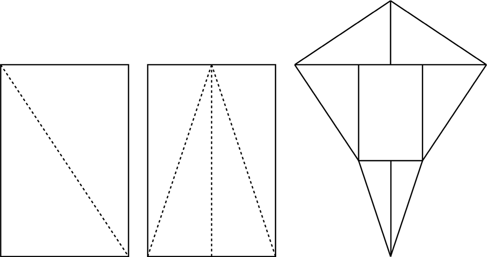
Traditionally, the concept of plane shapes is delivered through worksheets with a series of connect-the-dot tasks that walk the student through the creation of the assigned shape, or through the use of physical shape models (Figure 8-41). Making the connection between virtual concepts and their application in a physical world is known to improve content retention in addition to making math fun.
Materials
You can find the files for this project at Thingiverse.com.
| Materials List | ||
Item | Quantity | Source |
1/4 × 3 × 4 in plywood | 1 | Home improvement store |
1/8 × 12 in wood dowel | 1 | Home improvement store |
18 in colored yarn | 1 | Craft store |
1 qt food storage bag | 1 | Grocery store |
| Makerspace Tools and Equipment |
Laser engraver |
Ruler |
Sandpaper |
Wire strips |
Setup
- Step 1
- Import the planeBoard.dxf file into the default template’s layout and create an array of boards to meet your quantity and material constraints. Follow your laser cutter’s operating procedure for configuring the machine for cutting. Send your drawing to the machine, power on the exhaust fan and air assist, and begin cutting.
- Step 2
- Each pegboard requires 10 1-inch pegs. Mark each wooden dowel with 1 in graduations using a pen and use the largest gauge cutter on your wire strippers to cut off each peg. Feed the yarn through the mounting holes located above the peg holders and secure it in place with a knot. Store the board and the pegs in a ziplock bag to prevent the loss of parts.
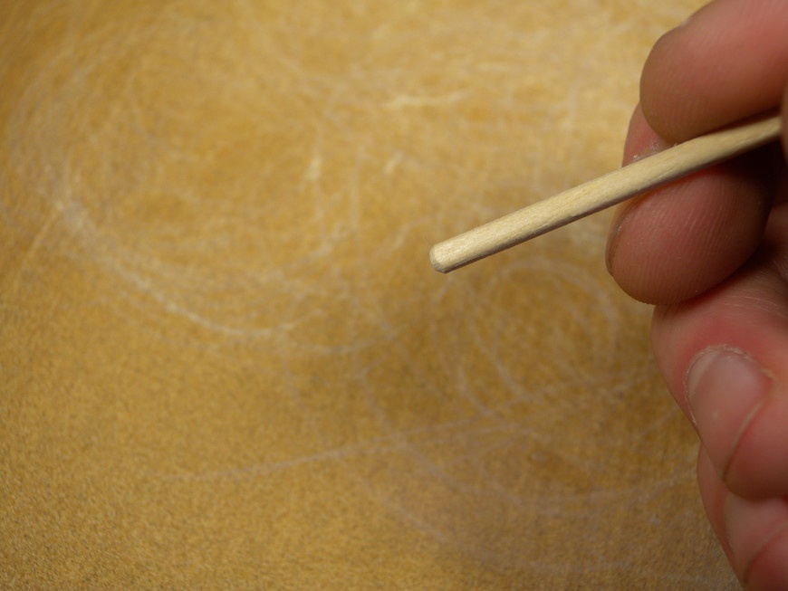
Check that the ends of the pegs are free of splinters by gently dragging the ends across the sheet of sandpaper until smooth (Figure 8-42).
Procedure
- Step 1
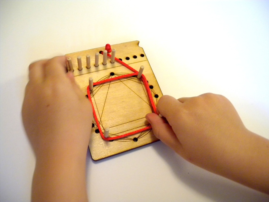
- Set up the board by unwrapping the yarn and laying it flat on your work surface. Place the pegs into their respective positions at the top of the board. Use the pegs to create as many plane shapes as possible (Figure 8-43).
Lab #14: Making a Pythagorean Calculator
- Subject
- Math
- Grade Level
- 6–8
- Lab Type
- Learning Tool
- Estimated Class Time
- 45 Minutes
- Objective
- As students become more and more reliant on calculators, their ability to predict the numerical outcome of a problem and know when the calculated outcome is correct is greatly diminished. Providing students with tools that provide a physical representation of their calculation helps develop better math skills and gives them the ability to more accurately predict outcomes prior to using a calculator.
Overview
The Pythagorean theorem is a widely used formula for calculating the length of any side of a right triangle when two lengths are known:
A2 + B2 = C2
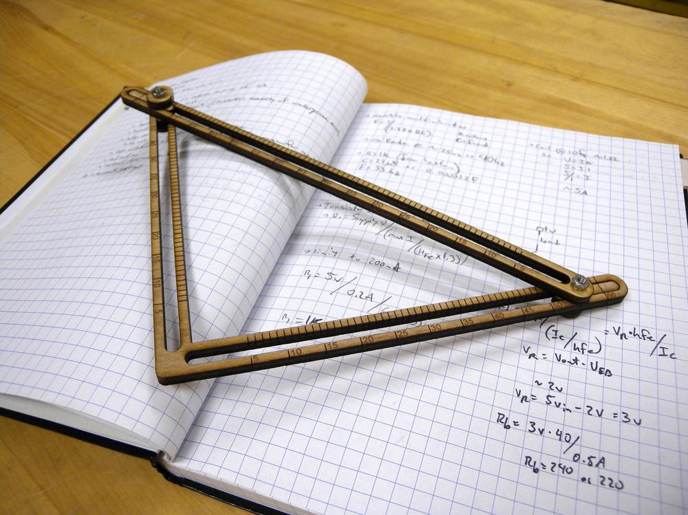
This formula is widely used in engineering for determining material lengths and can easily be calculated without a conventional calculator. This lab is designed to produce a measurement tool that is capable of calculating and demonstrating the correlation between all three sides of a right triangle. The resulting tool (Figure 8-44) serves as an excellent means for students to make connections between their formulas and the physical world.
Materials
You can find the files for this project at Thingiverse.com).
| Materials List | ||
Item | Quantity | Source |
1/8 in plywood sheet | 1 | Home improvement store |
4-40 × 1 in pan head machine screw | 2 | Home improvement store |
4-40 wing nut | 2 | Home improvement store |
#4 washer | 1 | Home improvement store |
| Makerspace Tools and Equipment |
Laser engraver |
Setup
- Step 1
- Open the pyCalc.dxf file in your CAD software suite and create an array for the quantity of calculators that you want to make. Follow your laser cutter’s operating procedure for configuring the machine for cutting. Position the sheet of plywood on the cutting bed, send your drawing to the machine, power on the exhaust fan and air assist, and begin cutting.
Procedure
- Step 1
- Place one of the large wooden washers over a screw and then add a position indicator. Repeat this process for the remaining indicator. These indicators are used to identify the length of all three sides.
- Step 2
- Attach the hypotenuse gauge to the A2 / B2 side by gently sliding it over the two previously made indicators. They should move freely in the A2 / B2 gauge channels. Place another large wooden washer and then a steel washer over the screw and secure it in place by using a wing nut.
- Step 3
- Operate the gauge by sliding either the A2 or B2 sides into their desired position. You can read the angle of the B2 side relative to the hypotenuse by using the angle gauge.
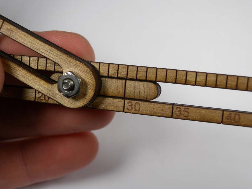
You can read the measurement (Figure 8-45) by noting the length of all three sides using the indicators.
Lab #15: Making a Parabolic Focuser
- Subject
- Math
- Grade Level
- 9–12
- Lab Type
- Learning Tool
- Estimated Time
- 1.5 Hours
- Objective
- Math lessons typically utilize virtual concepts with pen and paper explanations. The use of Makerspace technology to bring physical representations of the mathematical theory can help solidify student comprehension. The task of calculating and manipulating parabolic shapes and determining their focal point lends itself perfectly to such technology.
Overview
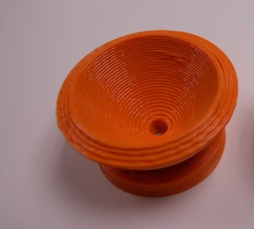
Algebra teaches about the fundamentals for calculating the shape of a parabola. Because a parabola has a definite focal point, it is well suited for focusing waves. This lab utilizes both 3D CAD software and a 3D printer to construct a tool (Figure 8-46) that demonstrates the location of the focal point of a calculated parabola.
Materials
You can find the files for this project at Thingiverse.com.
| Materials List | ||
Item | Quantity | Source |
1/8 × 4 in wooden dowel | 1 | Craft store |
Aluminum foil | 1 | Grocery store |
| Makerspace Tools and Equipment |
3D printer |
Spray adhesive |
Setup Procedure
- Step 1
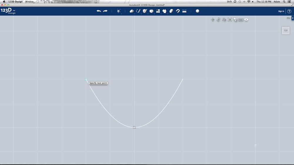
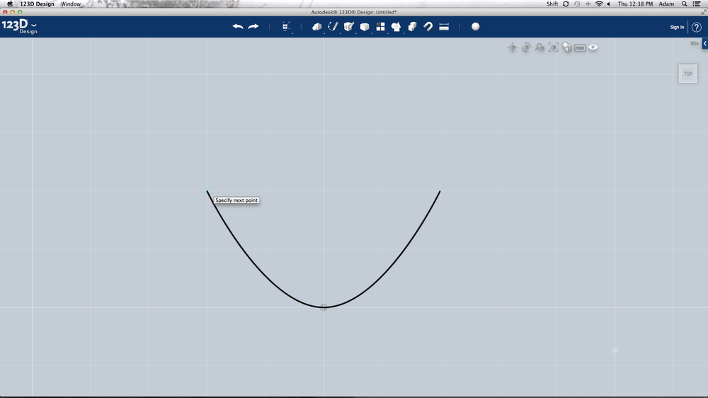
- Create a table of 10 coordinates, in addition to (0,0), that illustrate the 0.1X2 parabola. Open your 3D CAD software and create a new sketch on the Front plane, and set your measurement units to millimeters. Select the Point tool and produce 11 randomly placed points. One at a time, select a point and assign it the coordinates from your table. Use the Spline tool (Figure 8-47) to select the points from left to right. Exit the tool and you should have outlined the shape of your parabola.
- Step 2
- Select the Offset tool and produce an offset line 3 mm to the outside of your parabola and complete the shape by using the Line tool. Use the Line tool to bisect your parabolic shape and then use the Trim tool to trim away half of the outline.
- Step 3
- Select and use 3D Revolve and revolve your outline, turning your line drawing into a three-dimensional model. Make a new sketch on the Top plane and create a circle with a 20 mm diameter at the origin. Extrude the circle 3 mm above the Top plane.
- Step 4
- Create a new sketch on the Top plane and make another concentric circle at the origin with a 1/8 in diameter. This circle will be used to cut a hole for the dowel. Select the Extrude Cut tool and extrude this circle 1 cm through the model. For the 3D printer to construct your model it needs to be saved in the proper format. Select File, click Save As, and then click STL as the file type. Open the STL in your 3D printer’s control software. This software will “slice” your model into multiple layers and convert it to code that controls the printer. Generate the code and print.
- Step 5
- Carefully remove your parabolic model from the printer and clean away any excess plastic. Check and make sure that the dowel passes through the 1/8 in hole. Cut a small piece of aluminum foil from the roll and lay it on your desk, shiny side up. Spray a small amount of adhesive into the model and gently press in the aluminum foil. Make sure you smooth it as much as possible (Figure 8-48) because wrinkles will distort the reflection.
- Step 6
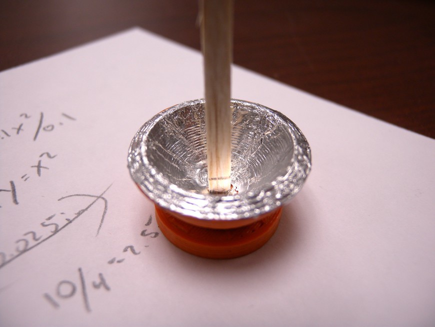
- Push the dowel into the parabolic model and make a mark with your pen indicating the base of the parabola (Figure 8-49). Position your model in front of the light source and mark the focal point with your pen.
