

Featuring several projects for turning an ordinary open patio into a custom outdoor room, this chapter is all about making the most of your patio space. A patio room is more of a design concept than a specific type of structure. The idea is to enhance a space with just the right elements to make it more usable, comfortable, or private.
If your patio feels just a little too exposed or if the layout could use some definition and a sense of enclosure, an overhead or side screening could be just what’s needed to complete your outdoor oasis. If you like the protection of a covered patio but don’t want a solid roof overhead, then a patio enclosure may be the perfect alternative. Or, for a truly classic patio overhead, you can’t beat the look and subtle shading of a cedar arbor. You’ll even find a project for transforming the undesirable space under a second-story deck into a pleasant covered patio.
As for amenities, we’ve included two of the most popular backyard projects: an outdoor kitchen for the patio and landscape lighting, that can be used on a patio or walkway. If you’re building a new patio and want to include either of these amenities, be sure to plan for the utility hookups early in the process, in case you need to run lines under the patio surface.
In This Chapter:
 Under-deck Patio
Second-story walk-out decks can be a mixed blessing. On top, you have an open, sun-filled perch with a commanding view of the landscape. The space below the deck, however, is all too often a dark and chilly nook unprotected from water runoff. As a result, an under-deck area often ends up as wasted space or becomes a holding area for seasonal storage items or the less desirable outdoor furniture.
But there’s an easy way to reclaim all that convenient outdoor space—by installing a weatherizing ceiling system that captures runoff water from the deck above, leaving the area below dry enough to convert into a versatile outdoor room. You can even enclose the space to create a screened-in patio room.
The under-deck system featured in this project is designed for do-it-yourself installation. Its components are made to fit almost any standard deck and come in three sizes to accommodate different deck-joist spacing (for 12-inch, 16-inch, and 24-inch on-center spacing). Once the system is in place, the under-deck area is effectively “dried in,” and you can begin adding amenities like overhead lighting, ceiling fans, and speakers to complete the outdoor room environment.
The system works by capturing water that falls through the decking above and channeling it to the outside edge of the deck. Depending on your plans, you can let the water fall from the ceiling panels along the deck’s edge, or you can install a standard rain gutter and downspout to direct the water to a single exit point on the ground (see pages 203 to 205).
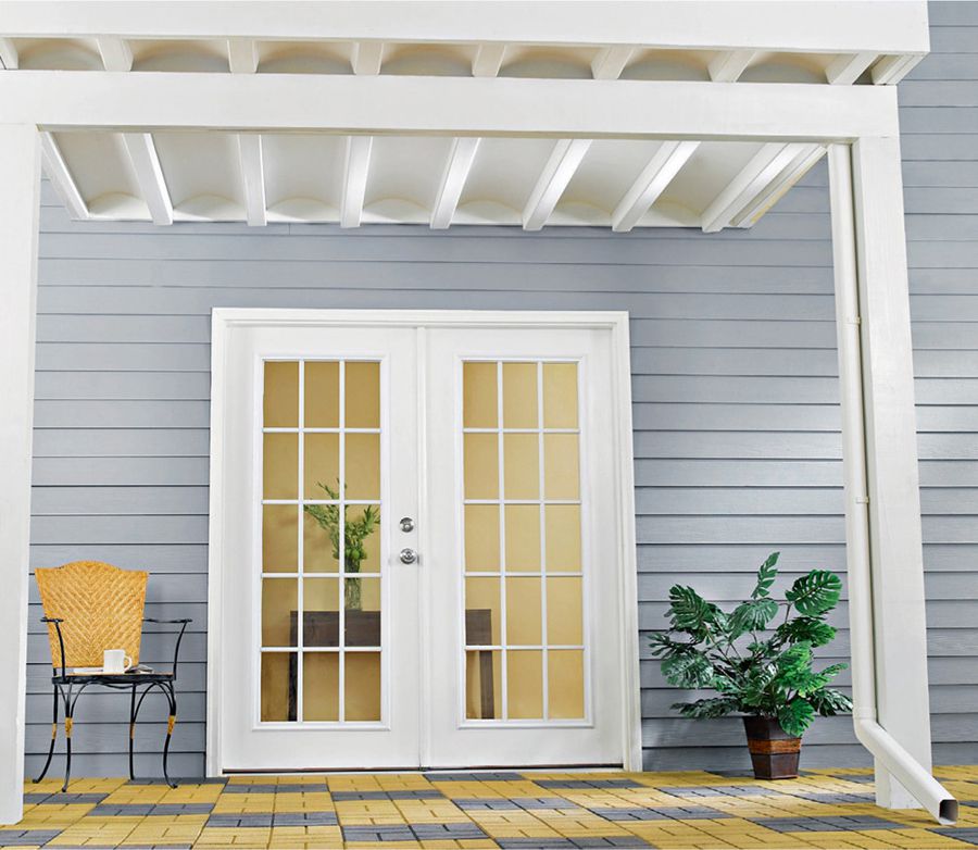
Made of weather-resistant vinyl, this under-deck system creates an attractive, maintenance-free ceiling—the perfect shelter for an open-air or enclosed patio space below.
 Design Tips
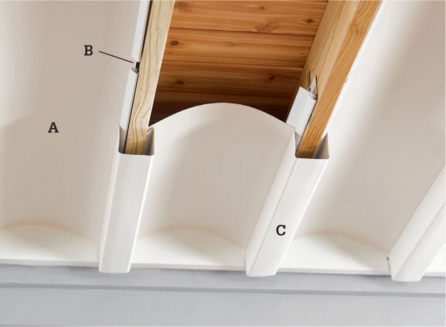
This under-deck system (see Resources, page 236) consists of four main parts: the joist rails mount to the deck joists and help secure the other components. The collector panels (A) span the joist cavity to capture water falling through the deck above. Water flows to the sides of the panels where it falls through gaps in the joist rails (B) and into the joist gutters (C) (for interior joists) and boundary gutters (for outer joists). The gutters carry the water to the outside edge of the deck.
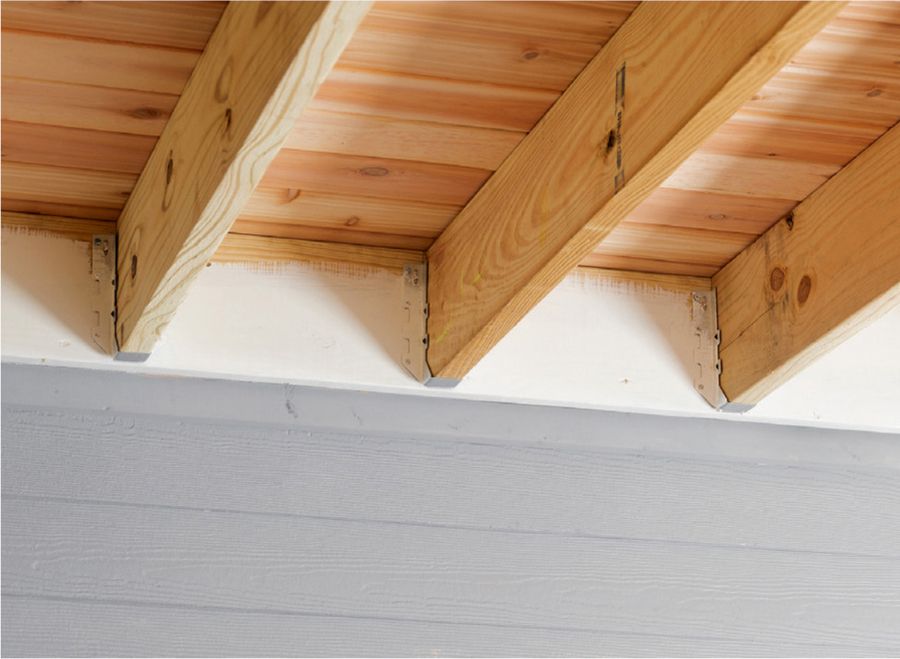
For a finished look, paint the decking lumber that will be exposed after the system is installed. Typically, the lower portion of the ledger board (attached to the house) and the outer rim joist (at the outer edge of the deck) remain exposed.
Consider surrounding architectural elements when you select a system for sealing off the area below your deck. Here, the under-deck system is integrated with the deck and deck stairs both visually and functionally.
 How to Install an Under-deck System
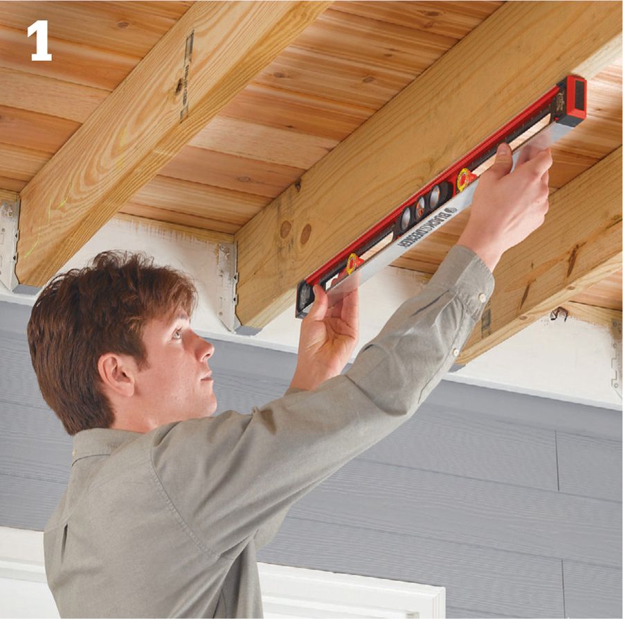
Check the undersides of several deck joists to make sure the structure is level. This is important for establishing the proper slope for effective water flow.
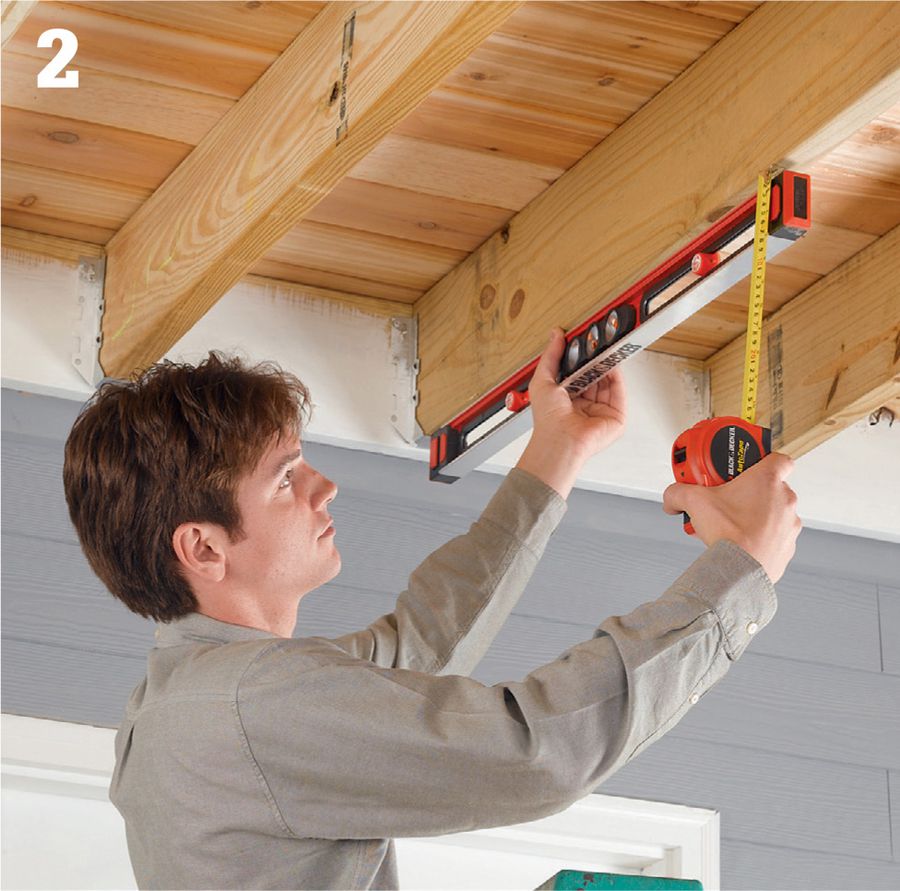
If your deck is not level, you must compensate for this when setting the ceiling slope. To determine the amount of correction that’s needed, hold one end of the level against a joist and tilt the level until it reads perfectly level. Measure the distance from the joist to the free end of the level. Then, divide this measurement by the length of the level. For example, if the distance is 1/4" and the level is 4 ft. long, the deck is out of level by 1/16" per foot.
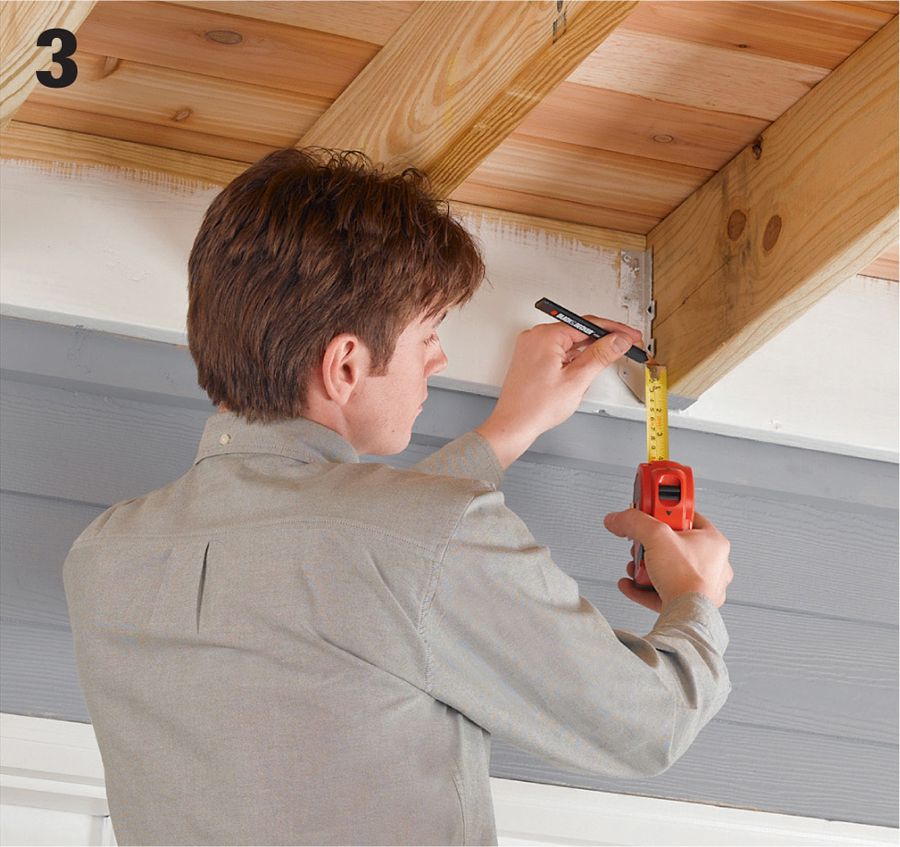
To establish the slope for the ceiling system, mark the ends of the joists closest to the house. Measure up from the bottom 1" for every 10 ft. of joist length (or approximately 1/8" per ft.) and make a mark. Add or subtract the out-of-level factor from step 2.
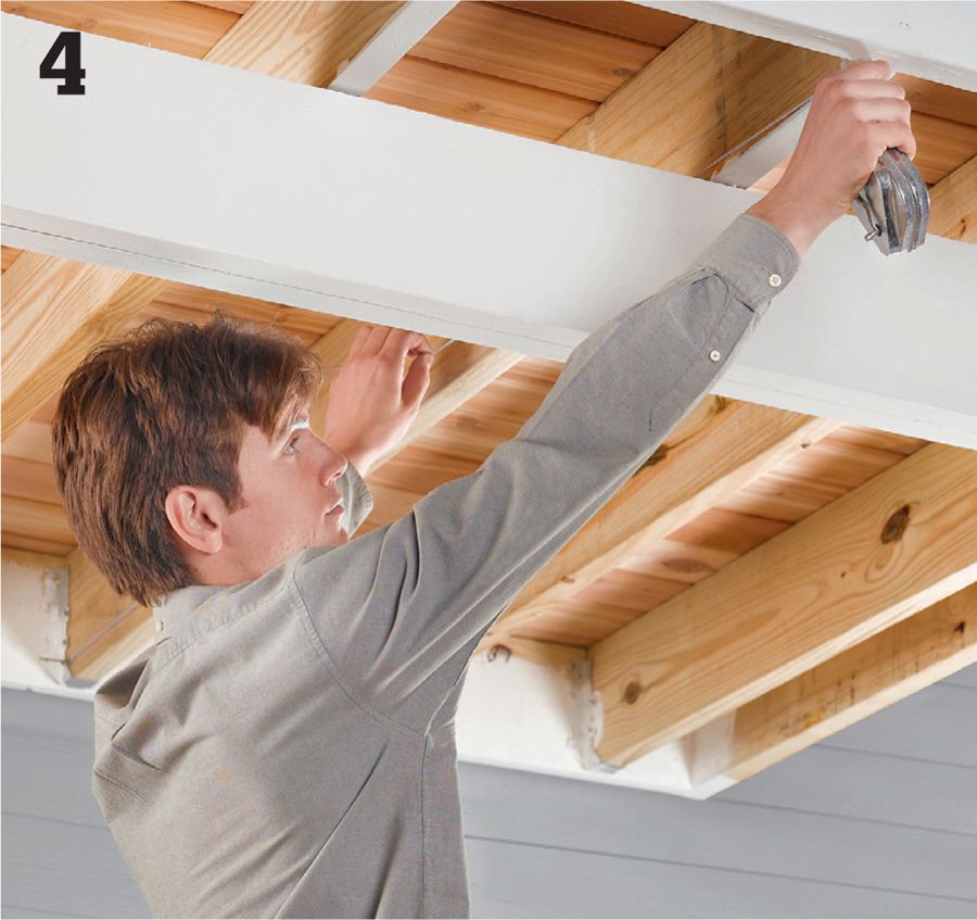
Create each slope reference line using a chalk line. Hold one end of the chalk line at the mark made in Step 3, and hold the other end at the bottom edge of the joist where it meets the rim joist at the outside edge of the deck. Snap a reference line on all of the joists.
Install vinyl flashing along the ledger board in the joist cavities. Attach the flashing with 1" stainless steel screws. Caulk along the top edges of the flashing where it meets the ledger and both joists using quality, waterproof acrylic caulk. Also caulk the underside of the flashing for an extra layer of protection.
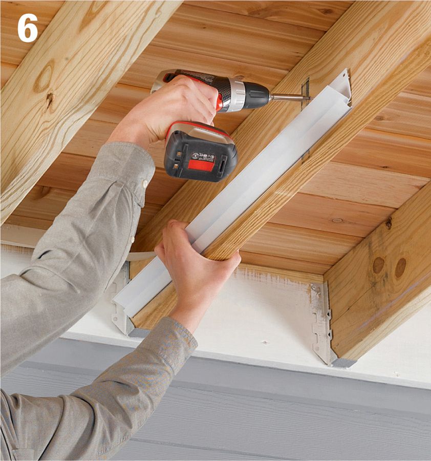
Begin installing the joist rails, starting 1" away from the ledger. Position each rail with its bottom edge on the chalk line, and fasten it to the joist at both ends with 1" stainless steel screws; then add one or two screws in between. Avoid over-driving the screws and deforming the rail. Leaving a little room for movement is best.
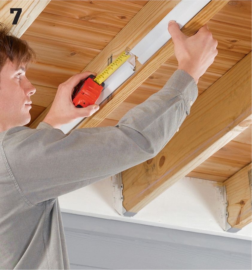
Install the remaining rails on each joist face, leaving a 1 1/2" (minimum) to 2" (maximum) gap between rails. Install rails along both sides of each interior joist and along the insides of each outside joist. Trim the final rail in each row as needed using aviation snips.
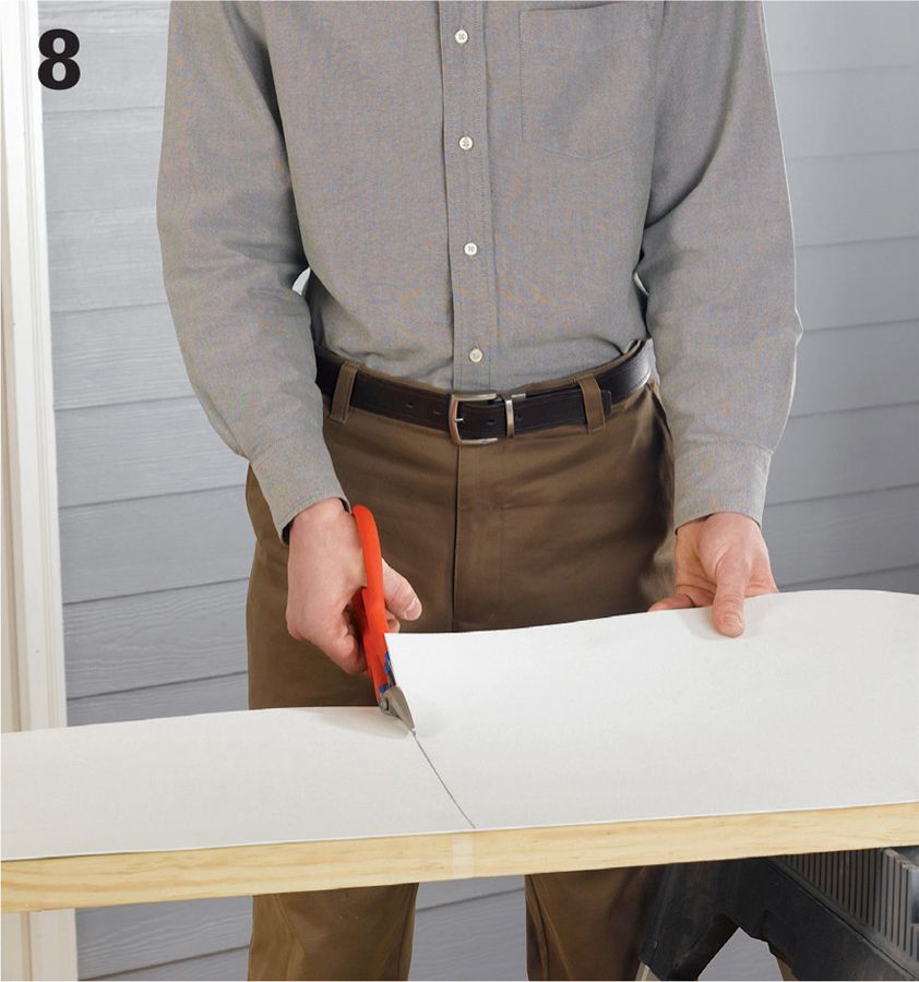
Measure the full length of each joist cavity, and cut a collector panel 1/4" shorter than the cavity. This allows room for expansion of the panels. For narrower joist cavities, trim the panel to width following the manufacturer’s sizing recommendations.
Scribe and trim the collector panels for a tight fit against the ledger board. Hold a carpenter’s pencil flat against the ledger, and move the pencil along the board to transfer its contours to the panel. Trim the panel along the scribed line.
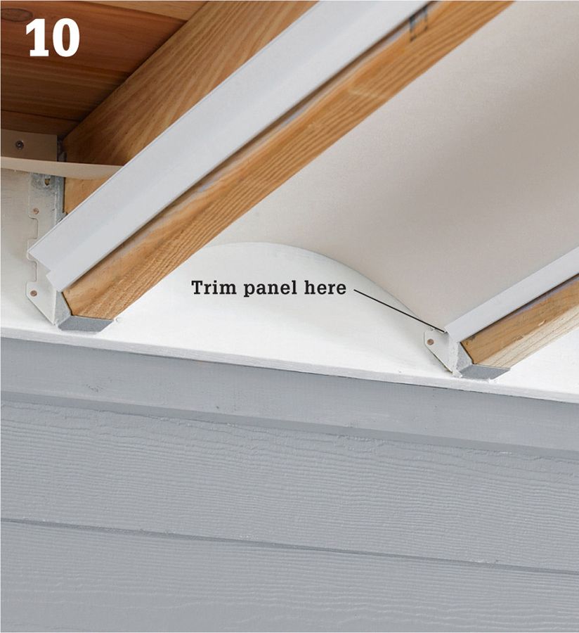
Trim the corners of the collector panels as needed to accommodate joist hangers and other hardware. This may be necessary only at the house side of the joist cavity; at the outer end, the 1/4" expansion gap should clear any hardware.
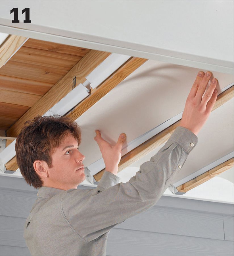
Install the collector panels, starting at the house. With the textured side of the panel facing down, insert one side edge into the joist rails, and then push up gently on the opposite side until it fits into the opposing rails. When fully installed, the panels should be tight against the ledger and have a 1/4" gap at the rim joist.
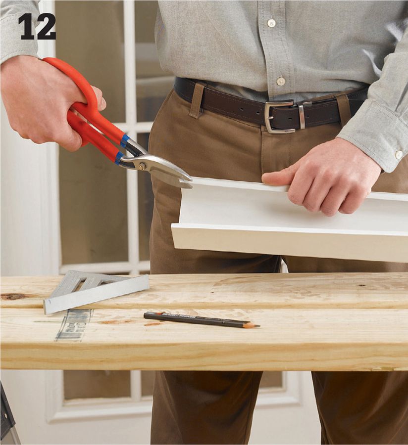
Prepare each joist gutter by cutting it 1/4" shorter than the joist it will attach to (if the joists rest on a structural beam, see page 202). On the house end of each gutter, trim the corners of the flanges at 45°. This helps the gutter fit tightly to the ledger.
Cut four or five 1/8" tabs into the bottom surface at the outside ends of the gutters. This helps promote the drainage of water over the edge of the gutter.
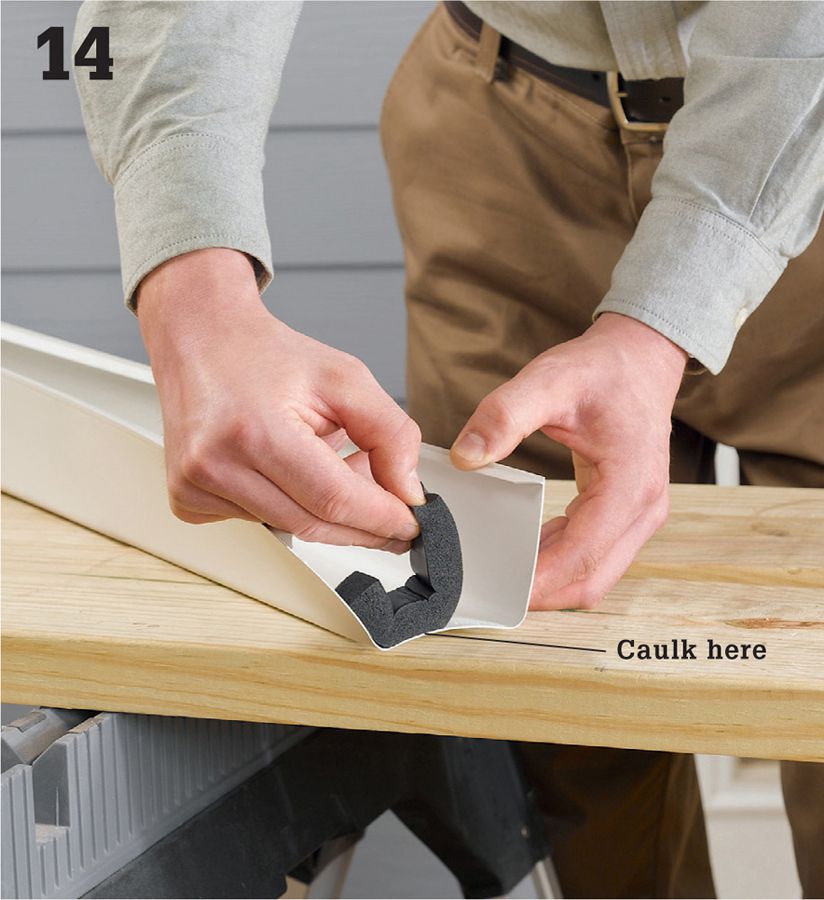
Attach self-adhesive foam weatherstrip (available from the manufacturer) at the home-end of each joist gutter. Run a bead of caulk along the foam strip to water-seal it to the gutter. The weather strip serves as a water dam.
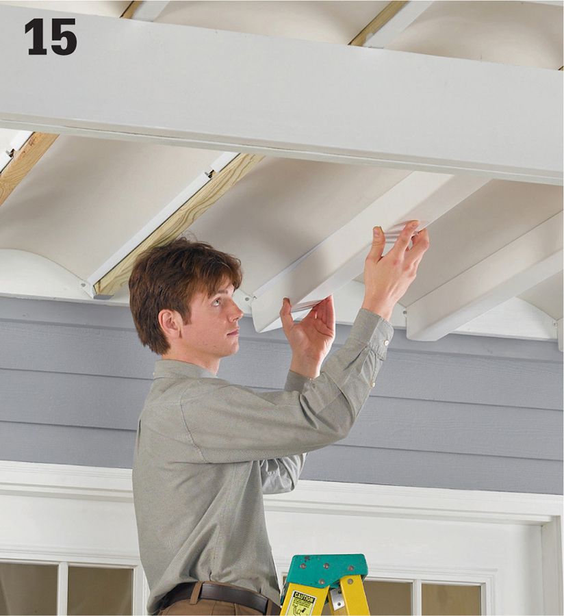
Install each joist gutter by spreading its sides open slightly while pushing the gutter up onto the joist rails until it snaps into place. The gutter should fit snugly against the collector panels. The gutter’s home-end should be tight against the ledger with the 1/4" expansion gap at the rim joist.
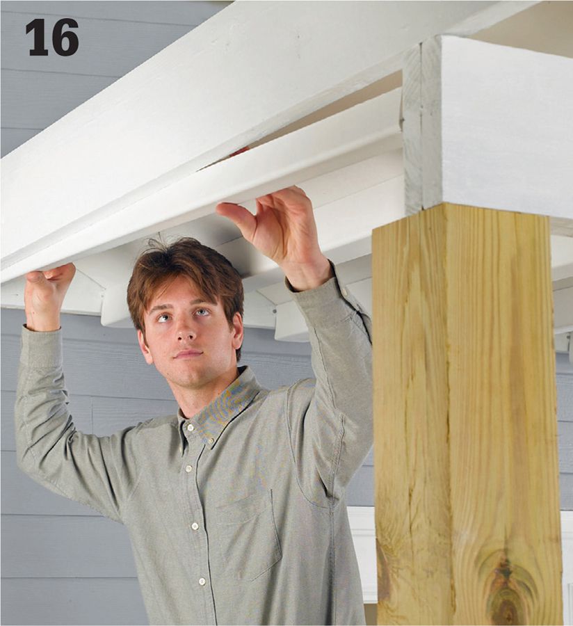
Prepare the boundary gutters following the same steps used for the joist gutters. Install each boundary gutter by slipping its long, outside flange behind the joist rails and pushing up until the gutter snaps into place. Install the boundary gutters working from the house side to the outer edge of the deck.
Run a bead of color-matched caulk along the joint where the collector panels meet the ledger board. This is for decorative purposes only and is not required to prevent water intrusion.
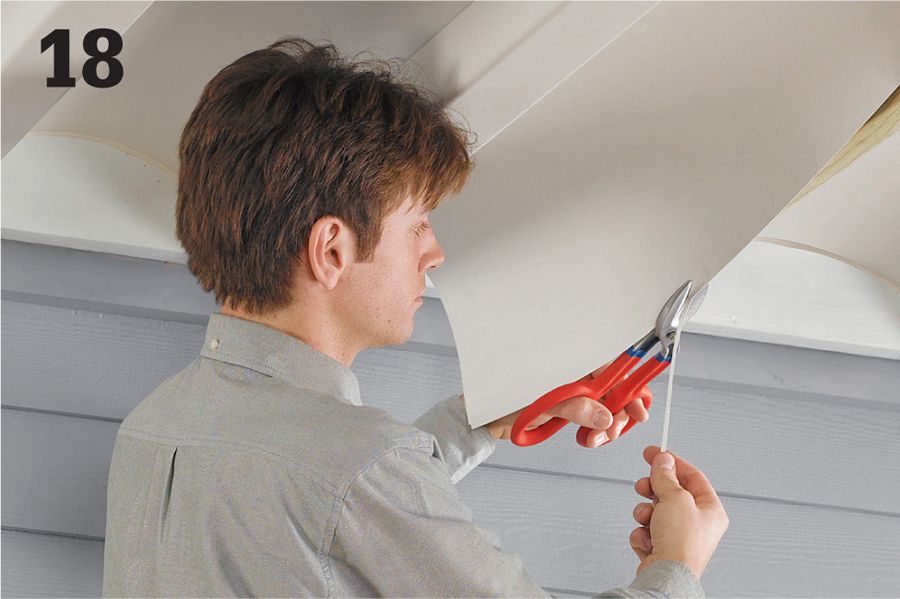
If collector panels are misshapen because the joist spacing is too tight, free the panel within the problem area, then trim about 1/8" from the side edge of the panel. Reset the panel in the rails. If necessary, trim the panel edge again in slight increments until the panel fits properly.
 Runoff Gutters
A basic gutter system for a square or rectangular deck includes a straight run of gutter channel with a downspout at one end. Prefabricated vinyl or aluminum gutter parts are ideal for this application. Gutter channels are commonly available in 10-foot and 20-foot lengths, so you might be able to use a single channel without seams. Otherwise, you can join sections of channel with special connectors. Shop around for the best type of hanger for your situation. If there’s limited backing to support the back side of the channel or to fasten into, you may have to use strap-type hangers that can be secured to framing above the gutter.
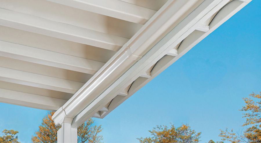
Runoff gutters are installed at the ends of the under-deck channels to capture runoff water and redirect it away from the enclosed area through downspouts.
 How to Install an Under-deck Runoff Gutter
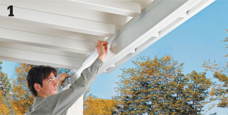
Snap a chalk line onto the beam or other supporting surface to establish the slope of the main gutter run. The line will correspond to the top edge of the gutter channel. The ideal slope is 1/16" per foot. For example, with a 16-ft.-long gutter, the beginning is 1" higher than the end. The downspout should be located just inside the low end of the gutter channel. Mark the beam at both ends to create the desired slope, then snap a chalk line between the marks. The high end of the gutter should be just below the boundary gutter in the ceiling system.
Install a downspout outlet near the end of the gutter run so the top of the gutter is flush with the slope line. If you plan to enclose the area under the deck, choose an inconspicuous location for the downspout, away from traffic areas.
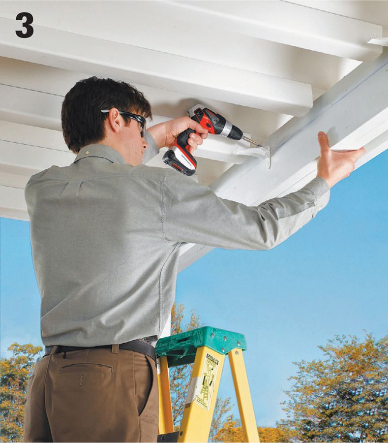
Install hanger clips (depending on the type of hangers or support clips you use, it is often best to install them before installing the gutter channel). Attach a hanger every 24" so the top of the gutter will hang flush with the slope line.
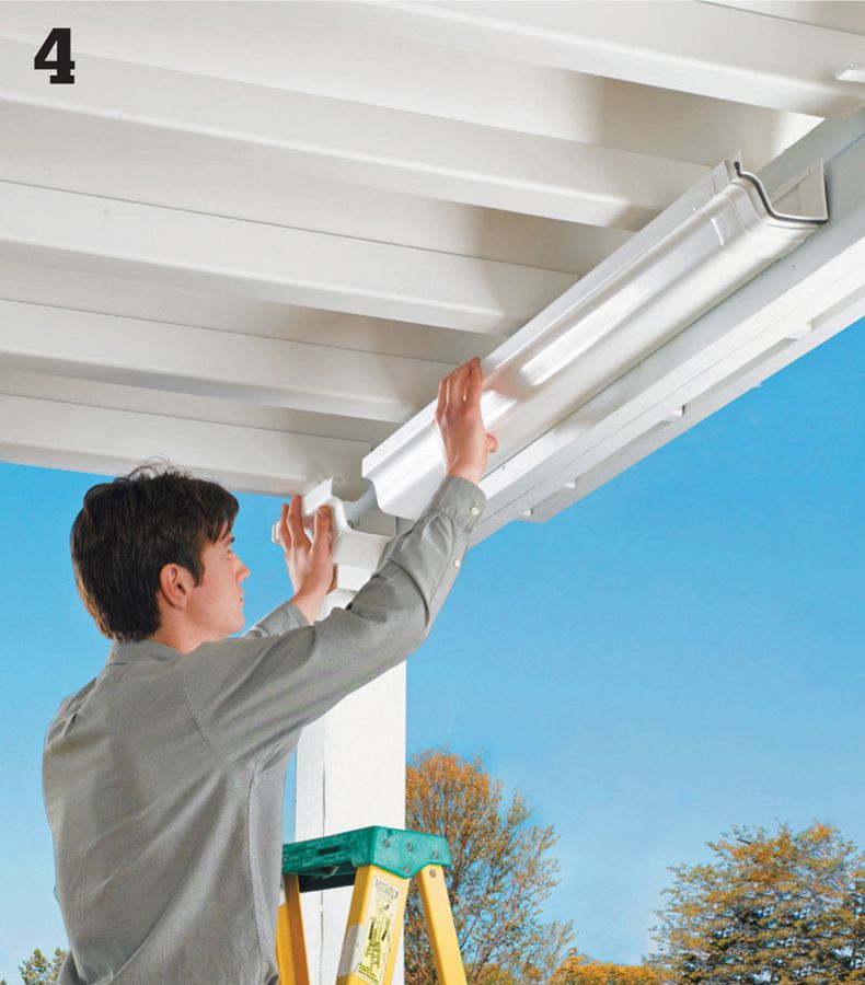
Cut sections of gutter channel to size using a hacksaw. Attach an end cap to the beginning of the main run, then fit the channel into the downspout outlet (allowing for expansion, if necessary) and secure the gutter in place.
Join sections of channel together, if necessary, for long runs using connectors. Install a short section of channel with an end cap on the opposite side of the downspout outlet. Paint the area where the downspout will be installed if it is unpainted.
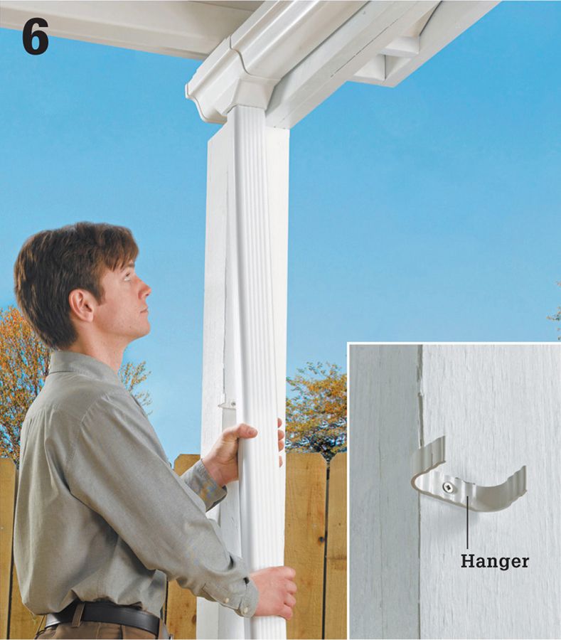
Cut the downspout piping to length and fasten an elbow fitting to its bottom end. Attach the downspout to the downspout outlet, then secure the downspout to a post or other vertical support using hangers (inset).
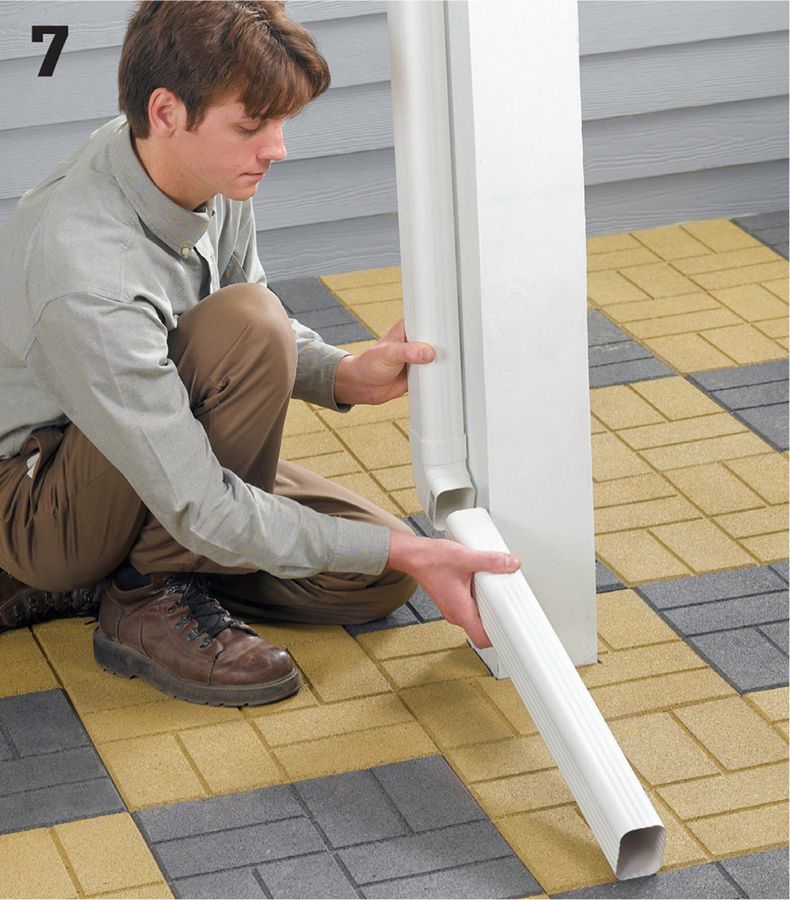
Cut a drainpipe to run from the downspout elbow to a convenient drainage point. Position the pipe so it directs water away from the house and any traffic areas. Attach the pipe to the downspout elbow. Add a splash block, if desired.
 Patio Enclosure
If you like the openness and plentiful light of a patio but want more protection from rain and strong winds, this stylish, contemporary patio shelter may be just what you’re looking for. Designed as a cross between an open-air arbor or pergola and an enclosed three-season porch, this patio structure has clear glazing panels on its roof and sides, allowing plenty of sunlight through while buffering the elements and even blocking harmful UV rays.
The roof of the patio shelter is framed with closely spaced 2 x4 rafters to create the same light-filtering effects of a slatted arbor roof. The rafters are supported by a doubled-up 2 × 10 beam and 4 × 6 timber posts. Because the shelter is attached to the house, the posts are set on top of concrete foundation piers, or footings, that extend below the frost line. This prevents any shifting of the structure in areas where the ground freezes in winter.
The patio shelter’s side panels cut down on wind while providing a degree of privacy screening. Their simple construction means you can easily alter the dimensions or locations of the panels to suit your own plans. In the project shown, each side has two glazing panels with a 3 1/2-inch space in between, for airflow. If desired, you can use a single sheet of glazing across the entire side section. The glazing is held in place with wood strips and screws so they can be removed for seasonal cleaning.
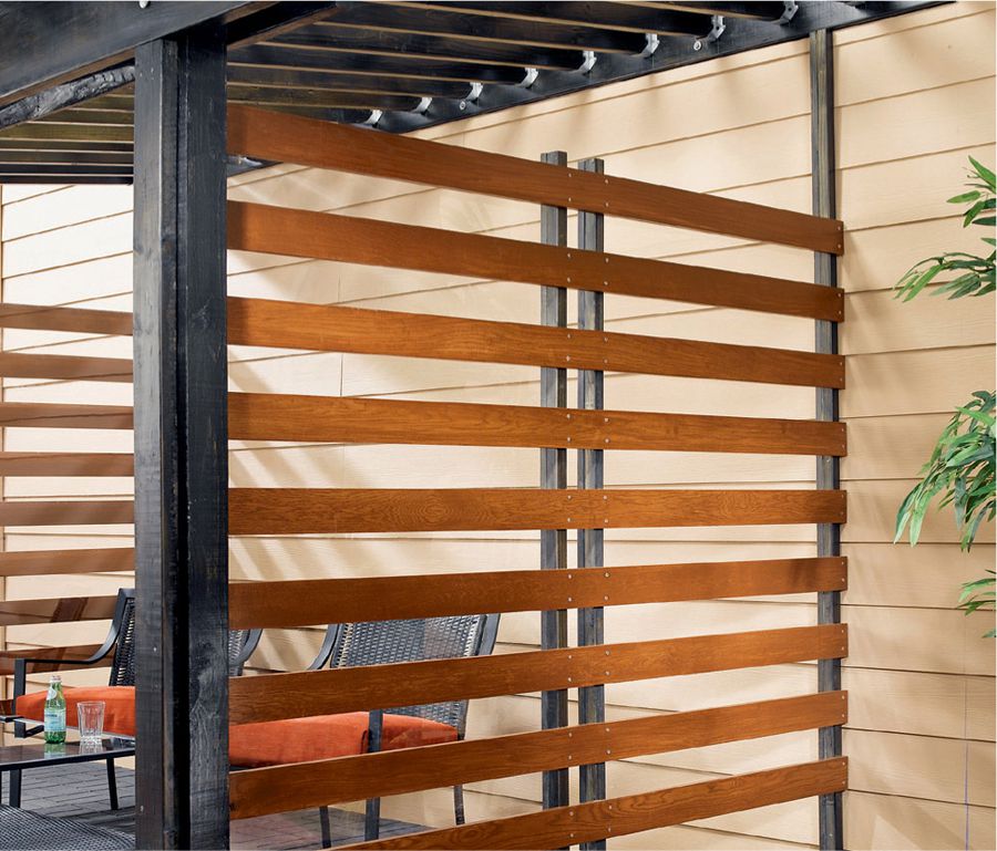
Slats of white oak sandwich clear polycarbonate panels to create walls that block the wind without blocking light and views.
Building against a solid wall and not in front of a patio door makes the space inside this contemporary shelter much more usable. The corrugated roof panels (see Resources, page 236) made of clear polycarbonate allow light to enter while keeping the elements out.
 Patio Enclosure Plans
 How to Build a Patio Enclosure
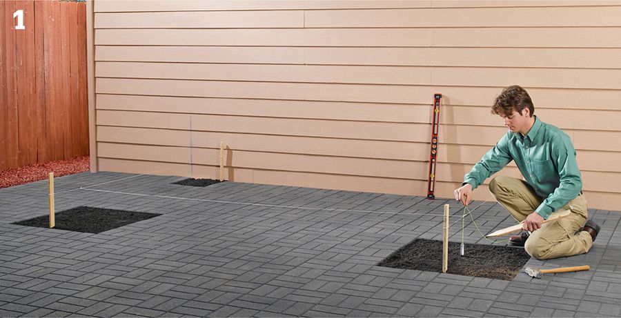
Mark the layout for the ledger board on the house wall. Lay out the post footing locations in the patio area. To mark the cutout for the ledger board, include the width of the ledger board, plus the height of the roofing, plus 1 1/2" for the flashing. The length of the cutout should be 1" longer than the length of the ledger board (12 ft. as shown). Plumb down from the ends of the ledger, then measure in to mark the locations of the post centers. At each of these points, run a perpendicular string line from the house out to about 2 ft. beyond the post locations. Set up a third string line, perpendicular to the first two, to mark the centers of the posts. Plumb down from the string line intersections and mark the post centers on the ground with stakes.
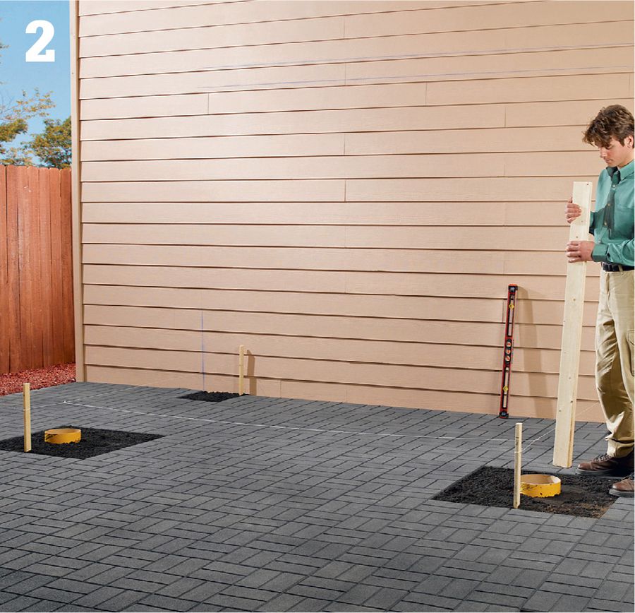
Dig a hole for a concrete tube form at each post location following the local building code for the footing depth. Add 6" of gravel and tamp it down. Position the tube forms so they are plumb and extend at least 2" above the ground. Backfill around them with soil and compact thoroughly.
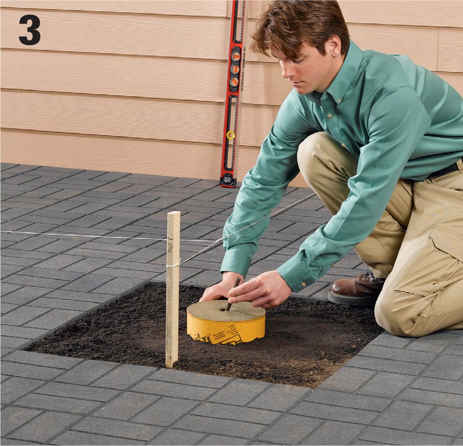
Fill the tube forms with concrete and screed it level with the tops of the forms. At each post-center location, embed a J-bolt into the wet concrete so it extends the recommended distance above the top of the form. Let the concrete cure.
Cut out the house siding for the ledger board using a circular saw. Cut only through the siding, leaving the wall sheathing. Note: If the sheathing is fiberboard instead of plywood, you may have to remove the fiberboard; consult your local building department. Replace any damaged building paper covering the sheathing.
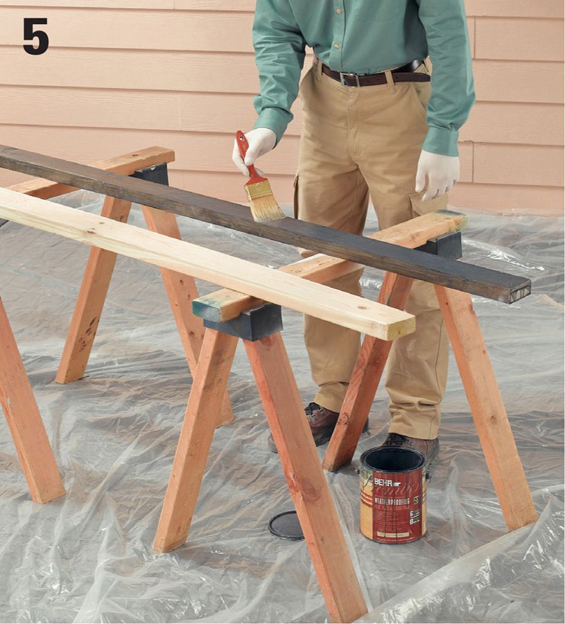
Stain the wood parts before you begin installing the shelter closure strips and panels. We used a black, semitransparent deck and siding stain.
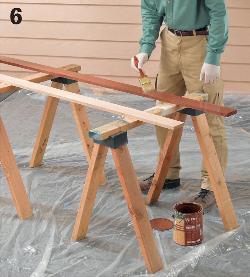
Apply a protective finish to the wood slats as desired. We used a semitransparent deck stain.
Install the ledger. First, slip corrugated roof flashing or metal roof flashing behind the siding above the ledger cutout so the vertical flange extends at least 3" above the bottom of the siding. Cut the ledger board to length. Fasten the ledger to the wall using 3/8 × 4" lag screws driven through counterbored pilot holes at each wall-stud location. Seal over the screw heads and counterbores with silicone caulk.
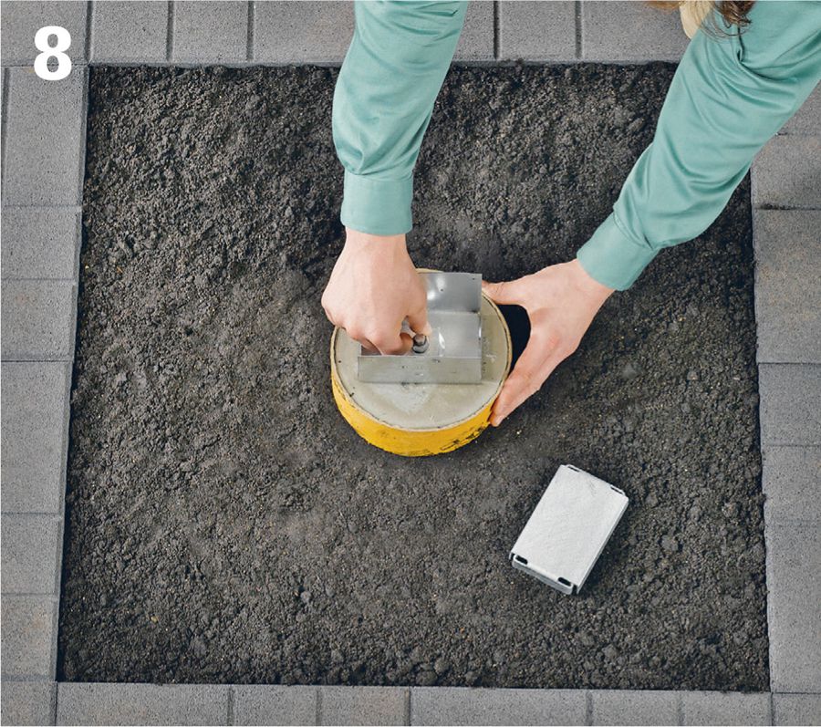
Anchor the post bases to the concrete footing, securing them with the base manufacturer’s recommended hardware. Make sure the bases are aligned with each other and are perpendicular to the house wall.
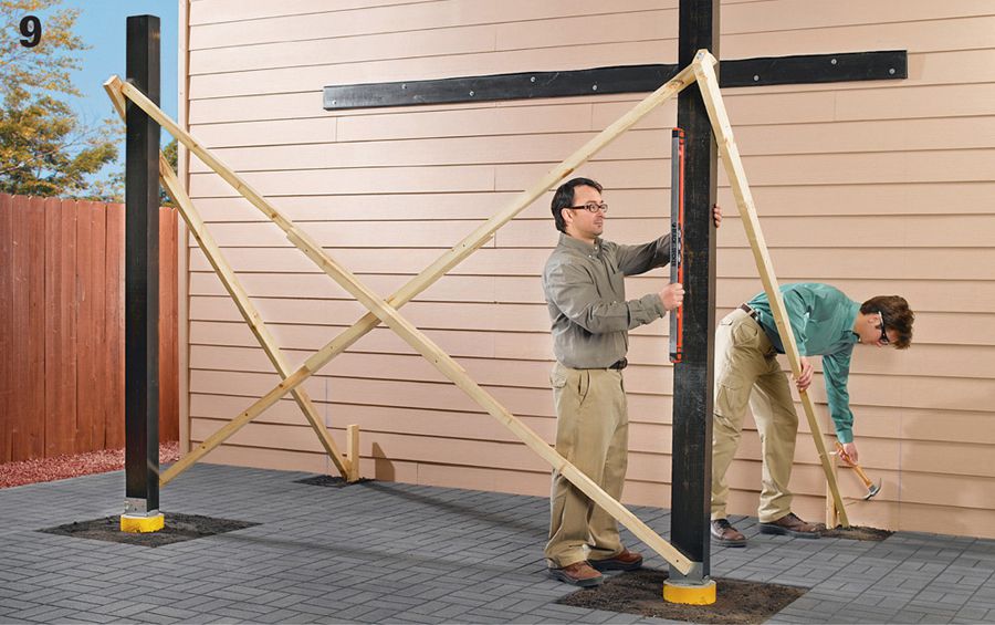
Cut off the bottom ends of the posts so they are perfectly square. Set each post in its base and hold it plumb. Fasten the post to the base using the manufacturer’s recommended fasteners. Brace the posts with temporary bracing. Note: You will cut the posts to length in a later step.
Cut a pattern rafter from 2 × 4 lumber using the desired roof slope to find the angle cut for the top end. Angle the bottom end as desired for decorative effect. Set the rafter in position so its top end is even with the top of the ledger and its bottom end passes along the side of a post. Mark along the bottom edge of the rafter onto the post. Repeat to mark the other post. Use a string and line level to make sure the post marks are level with each other.
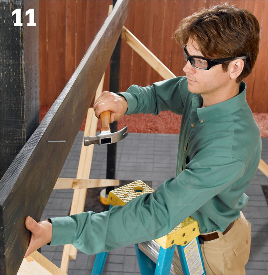
Cut the inner beam member to length from 2 × 10 lumber, then bevel the top edge to follow the roof slope. Position the board so its top edge is on the post markings, and it overhangs the posts equally at both ends (12" of overhang is shown). Tack the board in place with 16d nails.
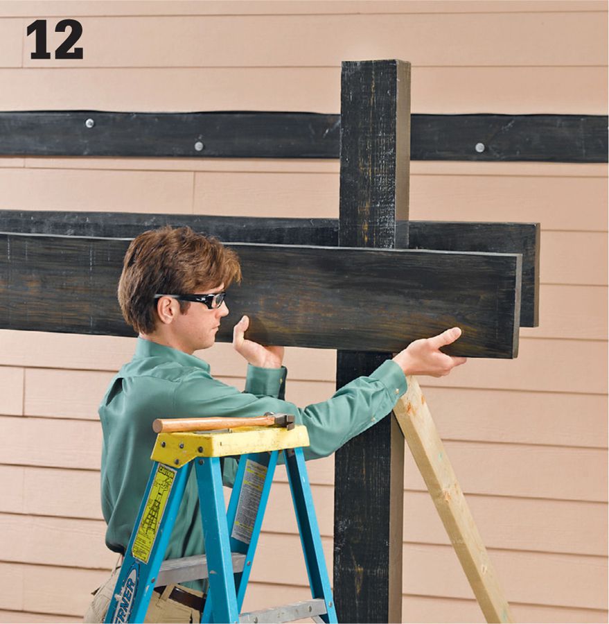
Cut the outer beam member to length from 2 × 10 lumber. Bevel the top edge following the roof slope, and remove enough material so that the bottom edges of the two beam members will be level with each other. Tack the member in place with nails.
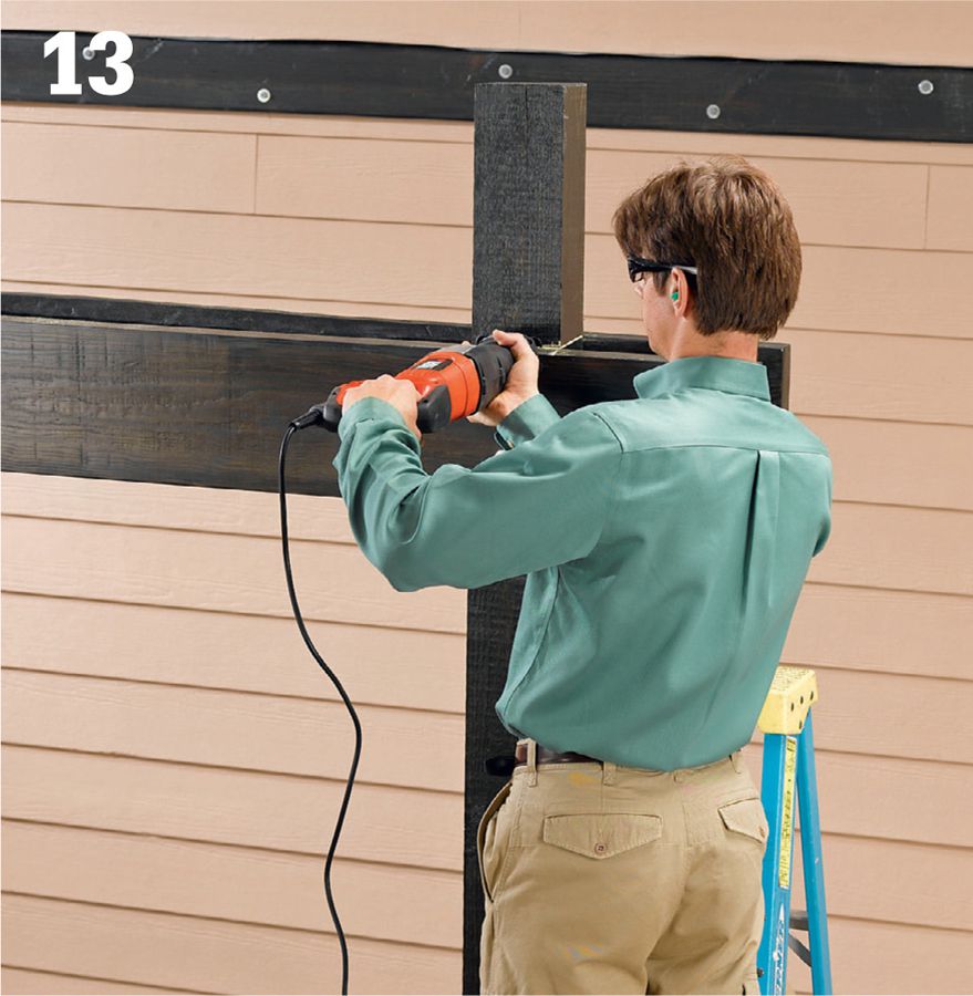
Anchor the beam members together and to the posts with pairs of 1/2"-dia. lag bolts and washers. Cut the posts off flush with the tops of the beam members using a handsaw or reciprocating saw.
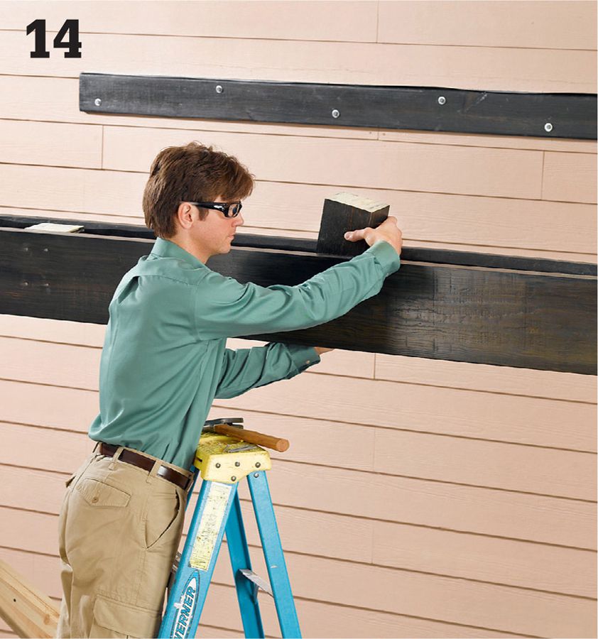
Trim the cutoff post pieces to length and use them as blocking between the beam members. Position the blocks evenly spaced between the posts and fasten them to both beam members with glue and 16d nails. Note: Diagonal bracing between the posts and beam may be recommended or required in some areas; consult your local building department.
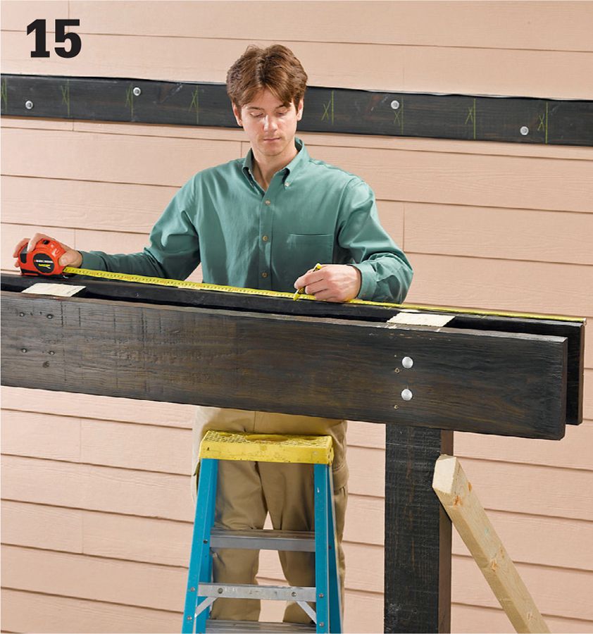
Mark the rafter layout onto the ledger and beam. As shown here, the rafters are spaced 9 1/2" apart on center. The two outer rafters should be flush with the ends of the ledger and beam.
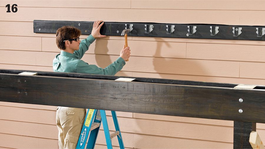
Install metal framing anchors onto the ledger for securing the top rafter ends using the anchor manufacturer’s recommended fasteners. Use the pattern rafter or a block to position the anchors so the rafters will be flush with the top of the ledger.
Use the pattern rafter to mark the remaining rafters and then cut them. Install the rafters one at a time. Fasten the top ends to the metal anchor using the recommended fasteners. Fasten the bottom ends to both beam members by toenailing one 8d nail through each rafter side and into the beam member.
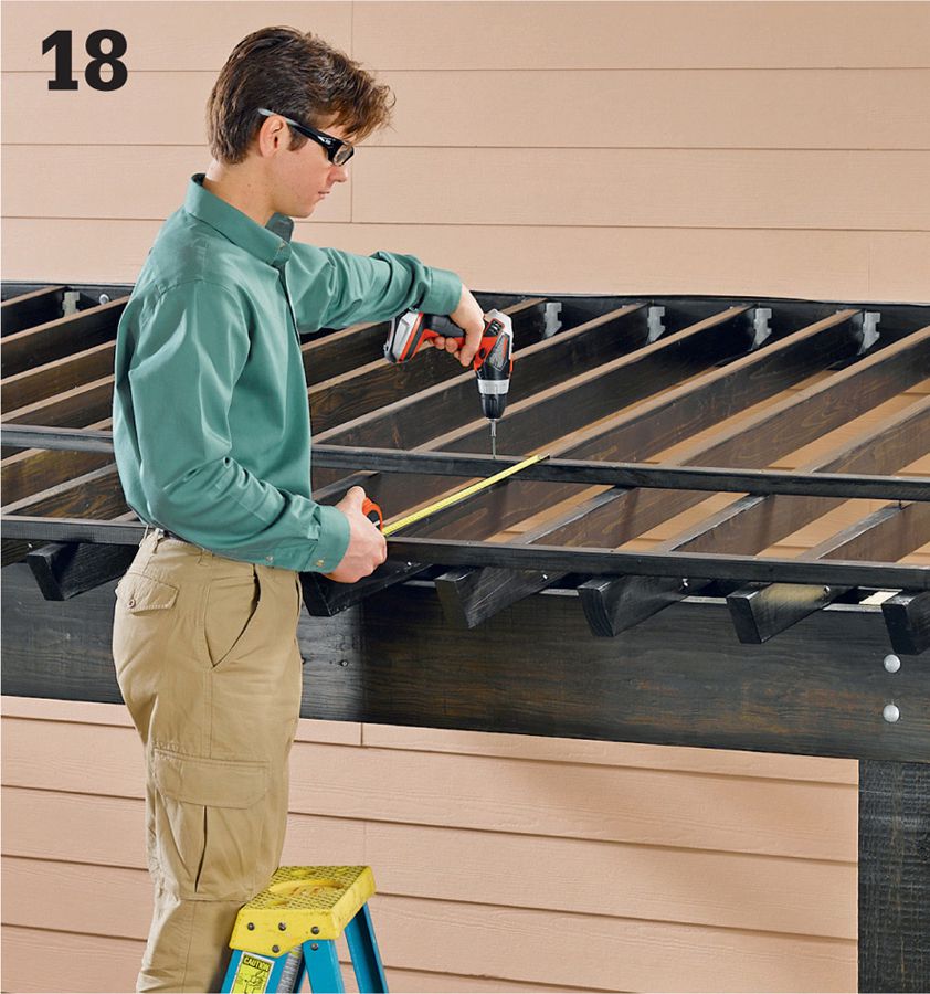
Install the 2 × 2 purlins perpendicular to the rafters using 3" deck screws. Position the first purlin a few inches from the bottom ends of the rafters. Space the remaining purlins 24" on center. The ends of the purlins should be flush with the outside faces of the outer rafters.
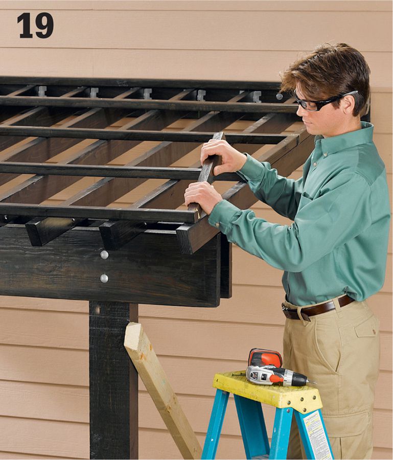
Add 2 × 2 blocking between the purlins along the outer rafters, and fasten them with 3" deck screws. This blocking will support the vertical closure strips for the roof panels.
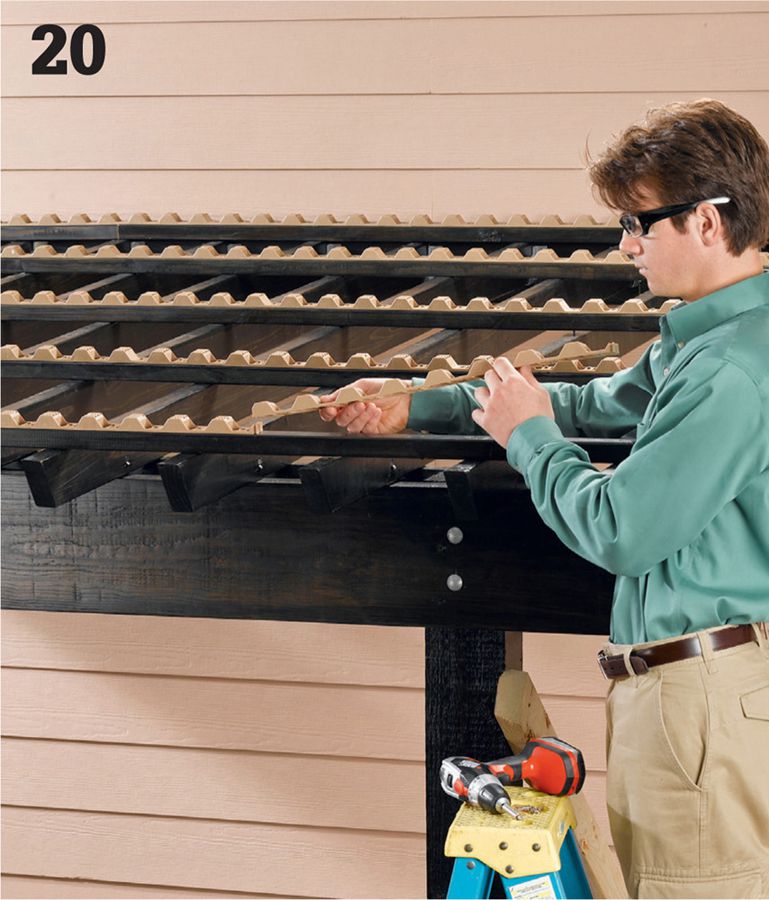
Starting at one side of the roof, install the roof panel closure strips over the purlins using the manufacturer’s recommended fasteners. Begin every run of strips from the same side of the roof, so the ridges in the strips will be aligned.
Add vertical closure strips over the 2 × 2 purlin blocking to fill in between the horizontal strips.
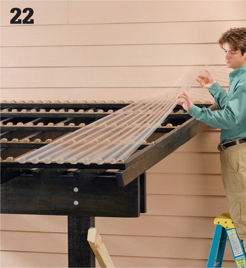
Position the first roofing panel along one side edge of the roof. The inside edge of the panel should fall over a rafter. If necessary, trim the panel to length or width following the manufacturer’s recommendations.
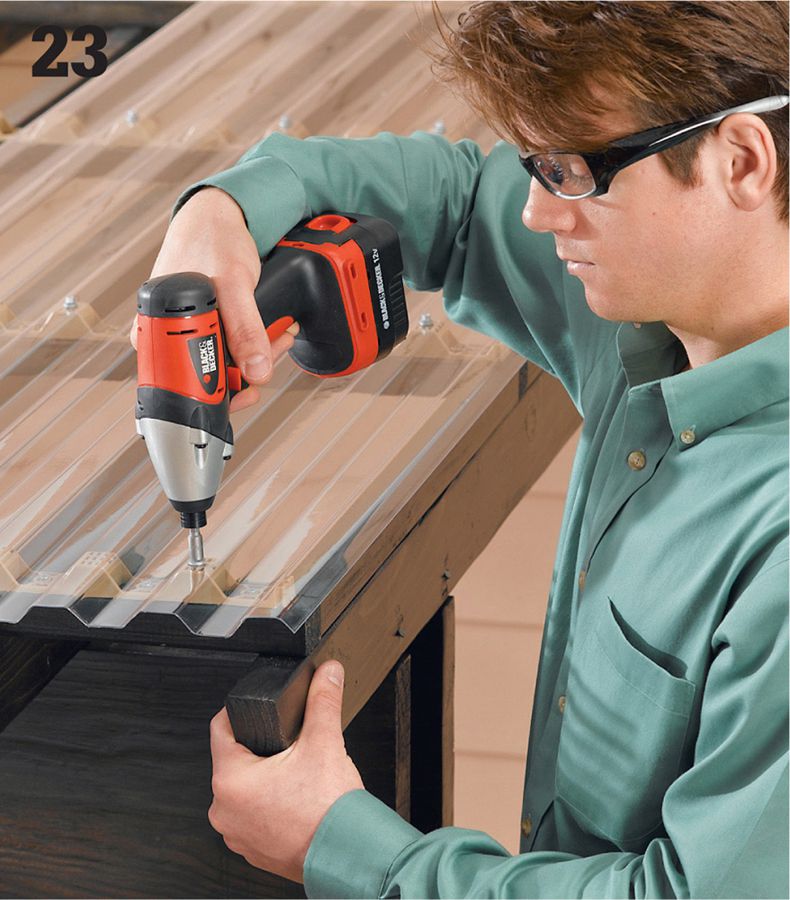
Drill pilot holes, and fasten the first panel to the closure strips with the recommended type of screw and rubber washer. Fasten the panel at the peak (top) of every other corrugation. Drive the screws down carefully, stopping when the washer contacts the panel but is not compressed. This allows for thermal expansion of the panel.
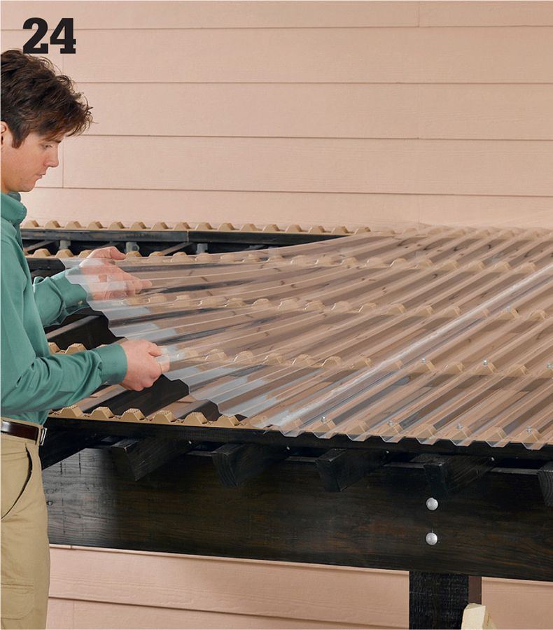
Apply a bead of the recommended adhesive/sealant (usually supplied by the panel manufacturer) along the last trough of the roofing panel. Set the second panel into place, overlapping the last troughs on both panels. Fasten the second panel. Install the remaining panels using the same procedure. Caulk the seam between the roof panels and the roof flashing.

To create channels for the side glazing panels, mill a rabbet into each of the eight vertical 2 × 2 cleats. Consult the glazing manufacturer for the recommended channel size, making sure to provide space for thermal expansion of the panels. Mill the rabbets using a table saw, router, or circular saw. Stop the rabbets so the bottom edges of the panels will be even with, or slightly above, the bottom edge of the lowest side slat.
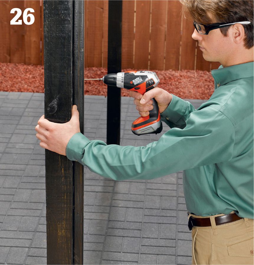
Position a cleat on each post at the desired height, with the cleat centered from side to side on the post. The rabbeted corner should face inside the shelter. Fasten the cleats to the posts with 3" deck screws. Fasten two more cleats to the house wall so they are aligned and level with the post cleats.
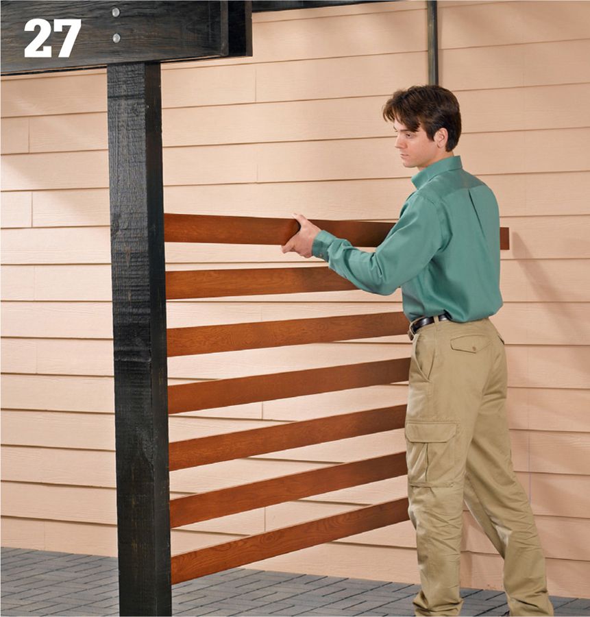
Cut the side slats to length to fit between the posts and the house wall. Mark the slat layouts onto the outside faces of the cleats, and install the slats with 1 1/2" deck screws or exterior trim-head screws. Space the slats 3 1/2" apart or as desired.
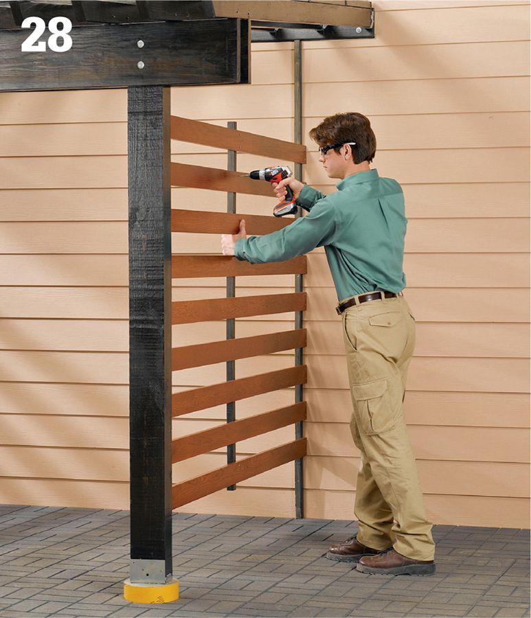
Fasten the middle cleats to the slats on each side, leaving about 3 1/2" of space between the cleats (or as desired). The cleats should overhang the top and bottom slats by 1 1/2" (or as desired).
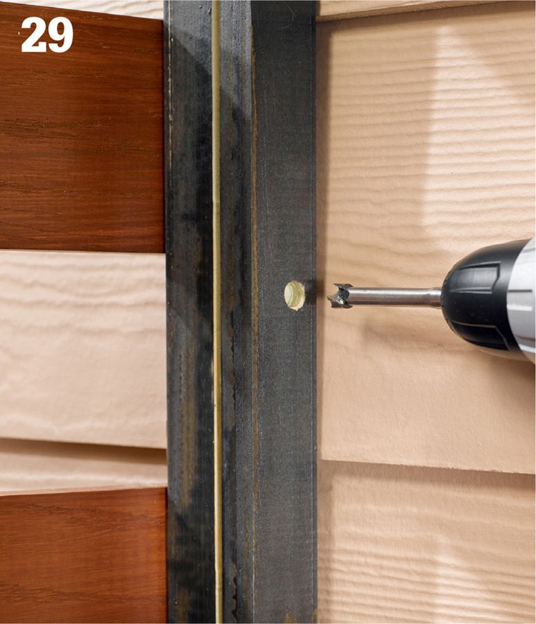
Cut the cap strips for the glazing panels from 1 × 2 material (or rip down strips from the 1 × 4 slat material). Position each cap over a cleat and drill evenly spaced pilot holes through the cap and into the cleat. Make sure the holes go into the solid (non-rabbeted) portion of the cleat. Drill counterbores, too (above). Drive screws to attach the post caps (next image).
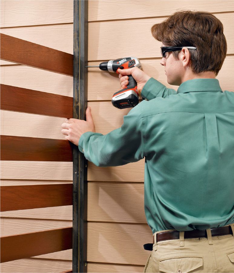
Trim the side glazing panels to size following the manufacturer’s directions. Apply neoprene or EPDM stripping or packing to the side edges of the panels. Fit each panel into its cleat frame, cover the glazing edges with the 1 × 2 caps, and secure the caps with 1 1/2" deck screws. Note: If the glazing comes with a protective film, remove the film during this step as appropriate and make sure the panel is oriented for full UV protection.
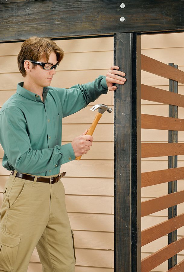
Option: Add a 2 × 4 decorative cap on the outside face of each post. Center the cap side-to-side on the post and fasten it with 16d casing nails.
 Screened Patio Room
A screening system is an ingeniously simple and effective way to enclose a covered patio—leaving you free to enjoy the outdoors at any time of day without the annoyance of insects and other pests. A basic system includes three main components: a base channel that mounts directly to the patio-roof posts, railings, and other framing members (as applicable); the screening (and spline); and a trim cap that snaps in place over the base channel to cover the screen edges and add a finished look to the installation. The base cap pieces are made to go together, but the screen and spline may need to be purchased separately. Be sure to follow the system manufacturer’s specifications for screen type and spline size. Screen systems are typically compatible with standard fiberglass and aluminum screen materials.
With the system shown in this project, each piece of screen is secured into the base channels using standard vinyl or rubber spline and a spline roller. The screen goes up quickly and easily after a little practice, and it doesn’t have to be perfectly tight right away; when the cap pieces are snapped on, they add tension to the screening, pulling it tight from all sides of the opening. This does a good job of eliminating the unsightly sag that occurs all too quickly with standard stapled-up screening. Replacing screen sections also is much easier with a screen system: just remove the surrounding cap pieces, pull out the spline, and install a new piece of screen.
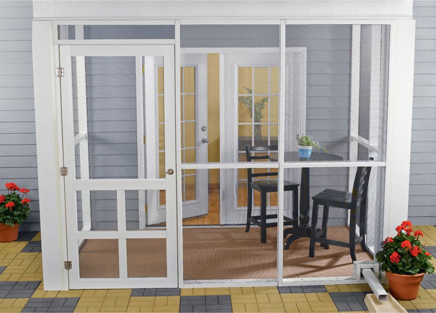
Screen systems are quick, easy products for screening in covered patios, including under-deck spaces like the patio shown here.
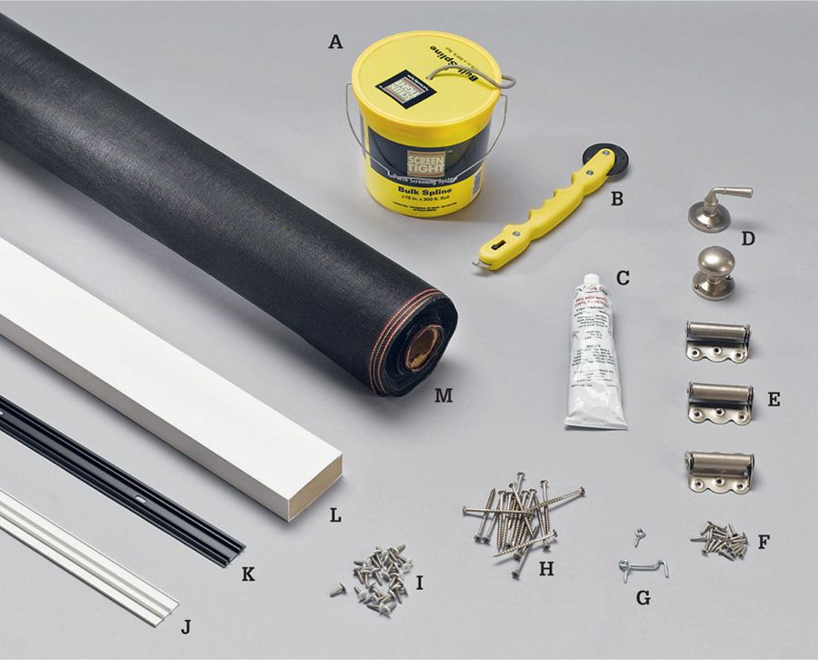
Spline-based screening systems are available at home centers and hardware stores and through many websites. Screen Tight, the system shown here (see Resources, page 236), is made with UV-resistant PVC and is available with trim colors of white, gray, beige, and brown. Parts of the system include: stretchable spline cord (A); spline roller (B); adhesive for bonding rigid vinyl (C); storm door handles (D); storm door hinges (E); 1" corrosion-resistant screws (F); screw-eye door latch (G); deck screws (H); decorative cap screws (I); track cap (J); track base (K); composite 2 × 4 (L); fiberglass screening (M).
 How to Install a Screening System
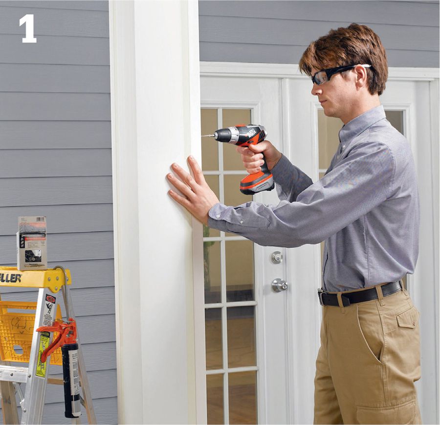
Begin installing the track backers that frame the openings you will be screening. You may use pressure-treated 2 × 4s or 2 × 2s. For a long-lasting and low-maintenance framework, we used composite 2 × 4-sized backers that came with the screen system materials. These products are quite new and are not rated for structural use. Attach the backers to the inside faces of the posts, centered, using exterior construction adhesive and 3 1/2" deck screws.
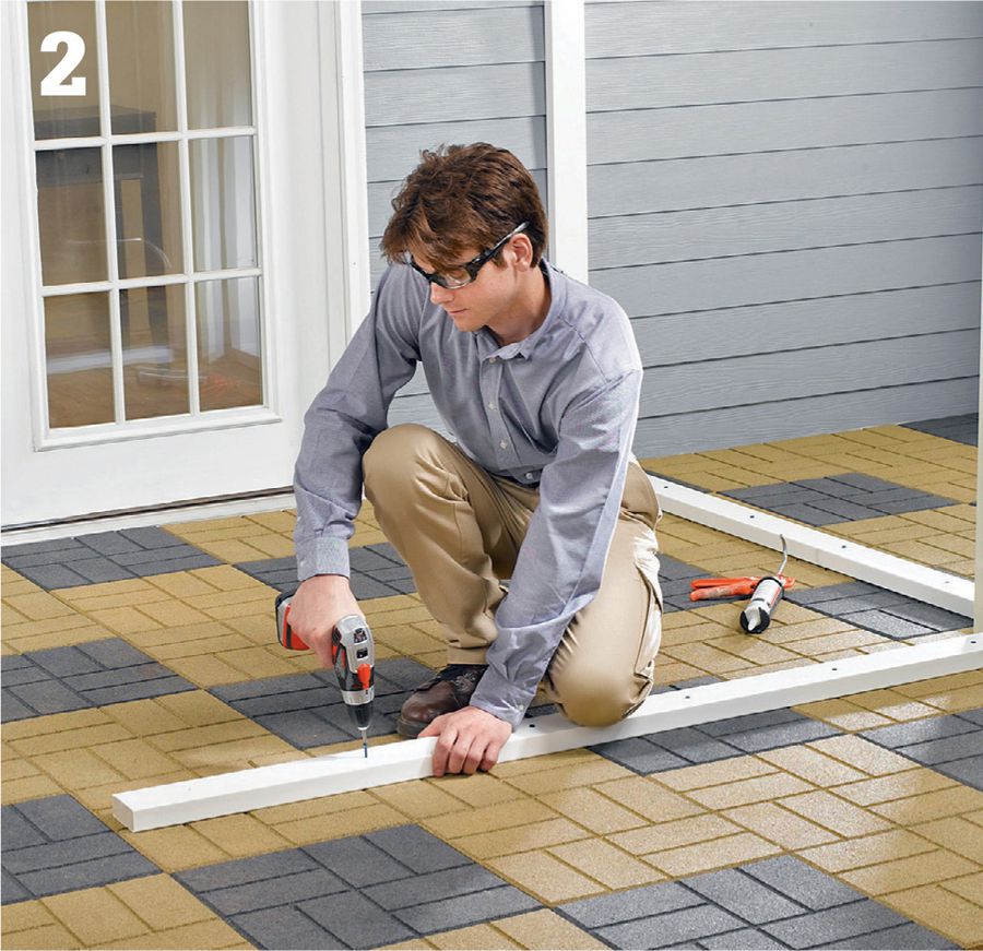
Secure sole plates to the patio or porch floor using construction adhesive and appropriate fasteners (use concrete anchors for concrete, stone, or paver patios and use deck screws for wood and nonwood decking).
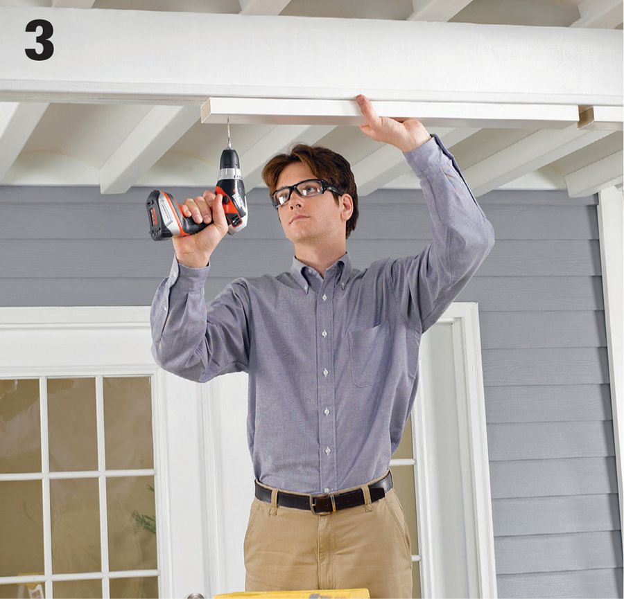
Attach cap plates to the beam or joist at the top of the installation area, leaving 1 1/2" between plates to create recesses for the vertical backers.
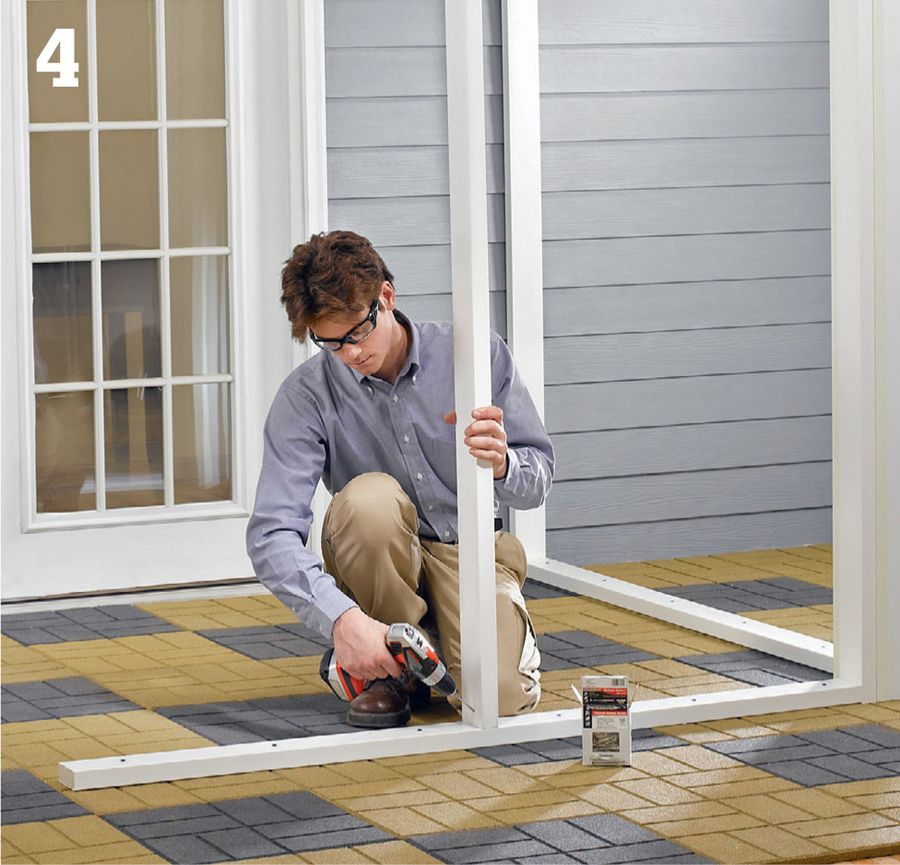
Install the vertical track backer members with the top ends fitted in the gaps you left in the cap plate. Make sure the vertical members are plumb and then drive deck screws toenail style through the members and into the sole plate. Also drive screws up at angles through the vertical members and into the beam or joist at the top of the area. Drill pilot holes.
Install the door header and the horizontal track backers using adhesive and deck screws. Locate the horizontal members 36 to 42" above the ground.
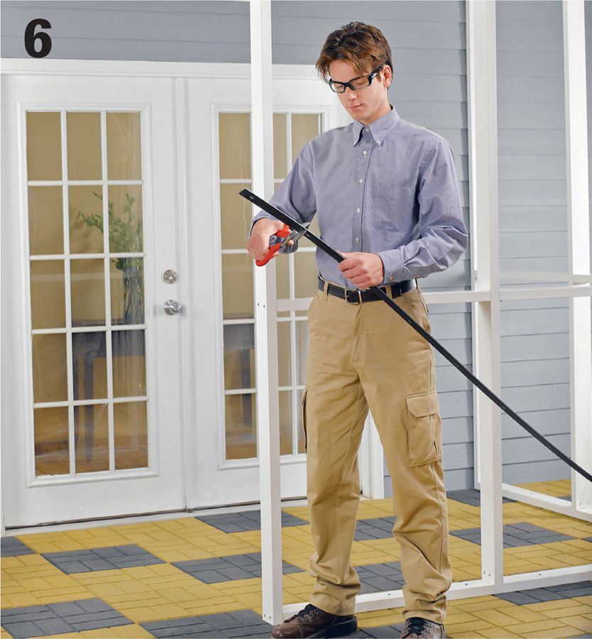
Cut a base channel to length for each vertical member in the screen frame. At the tops of the posts, hold the base channel back to allow room for the horizontal channels, if applicable (see step 12 photo). This results in less cutting of the cap trim later. Cut the channels using pruning shears or aviation snips.
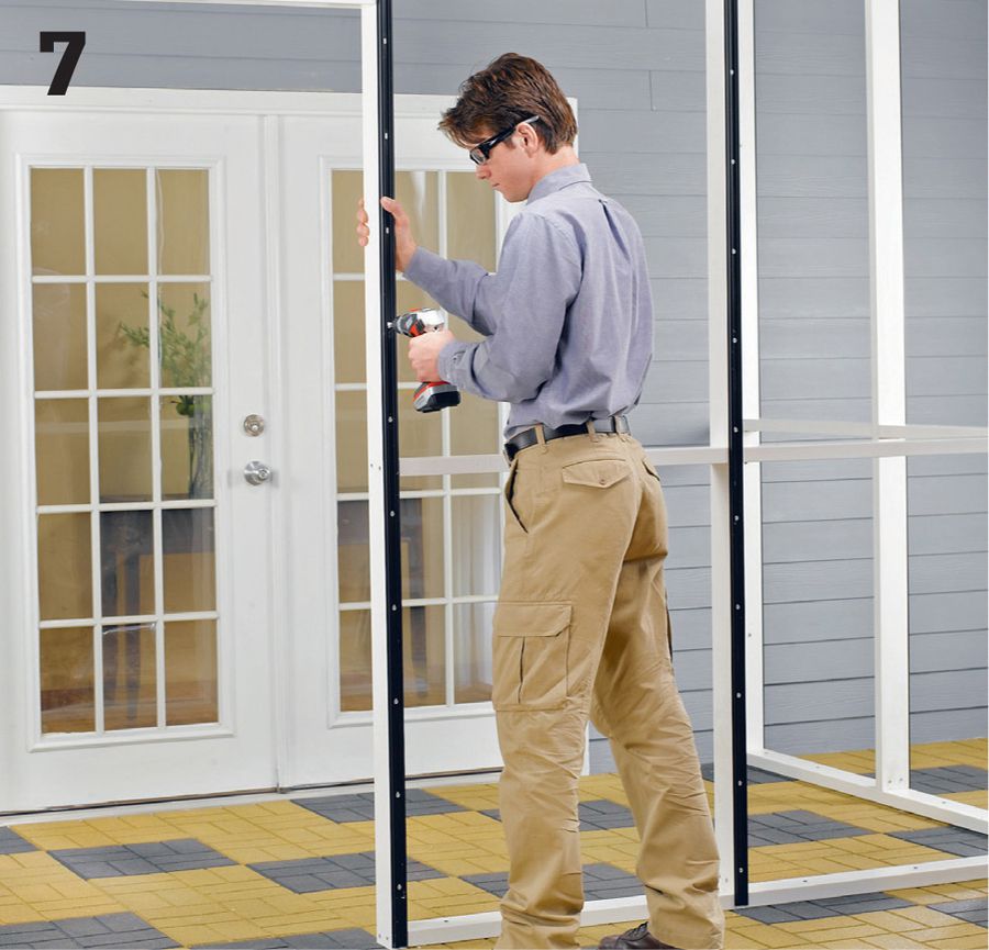
Fasten the vertical channel pieces to the framing with 1" corrosion-resistant screws. Drive a screw into each predrilled hole in the channel, then add a screw 2" from each end. Drive each screw in snugly but not so far that it warps the channel.
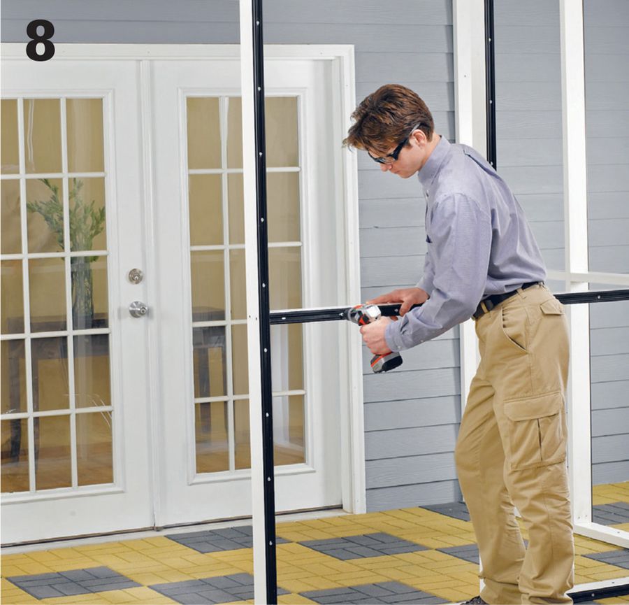
Cut the horizontal base channels to length and install them with screws. The butted joints where the horizontal channels meet the verticals don’t have to be precise or tight-fitting.
Begin installing the screen by positioning a full piece of screening over an opening so it overlaps several inches on all sides. Secure the screen into the horizontal base channel at one of the top corners using spline cord. You can plan to run the spline around the corners or cut it off at the ends as needed.
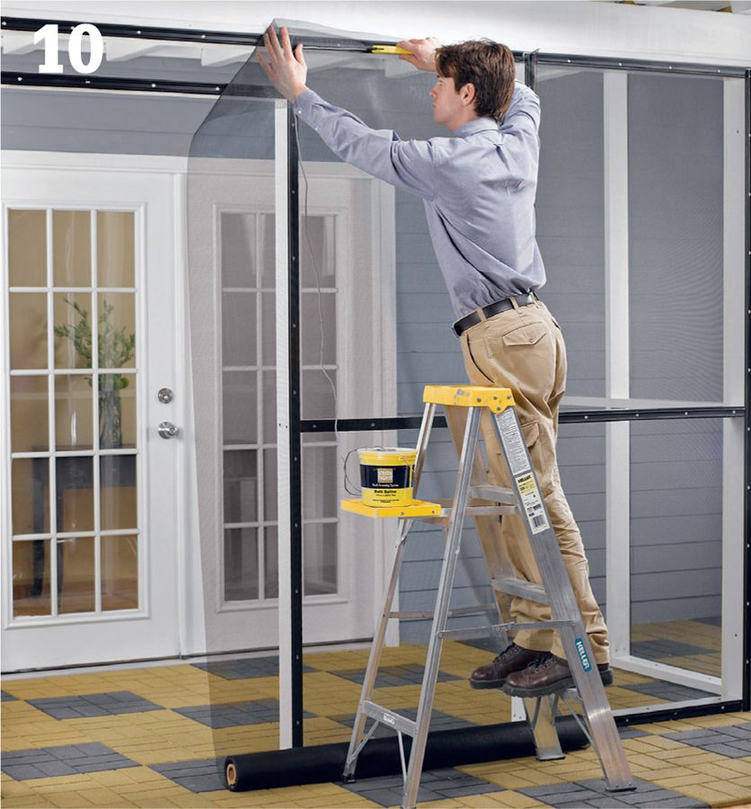
Embed the spline at the starting point, where it should fit fully into the groove of the base channel. Use a spline roller. Then, using one hand to pull the screen taut, press the spline into place to secure the screen along the top of the opening.
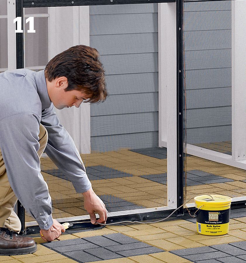
Secure the screen along both sides, then along the bottom using the same technique as for the top. When you’re finished, the screen should be flat and reasonably tight, with no sagging or wrinkling. If you make a mistake or the screen won’t cooperate, simply remove the spline and start over.
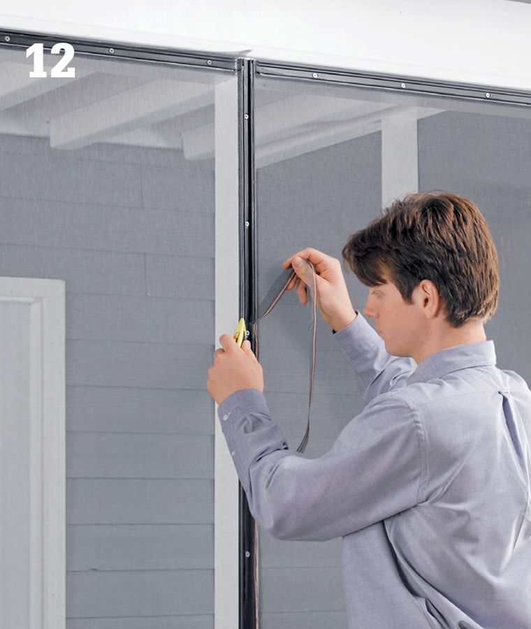
Trim off the excess screening with a sharp utility knife. Fiberglass screen cuts very easily, so control the knife carefully at all times. Repeat steps as needed to screen in the remaining openings.
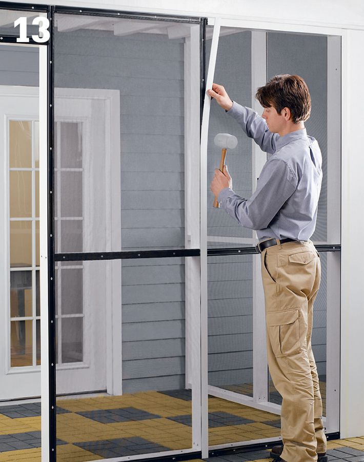
Install the trim caps over the base channels, starting with the vertical pieces. Working from the bottom up, center the cap over the base, then tap it into place using a rubber mallet. Tip: If you have a continuous horizontal band along the top of the screening, install those trim pieces before capping the verticals.
Cut the cap pieces to length as you install them. Mark cutting lines with a pencil, and make the cuts with pruning shears or aviation snips. If desired, use a square to mark a straight cutting line across the face or backside of the trim cap (inset).
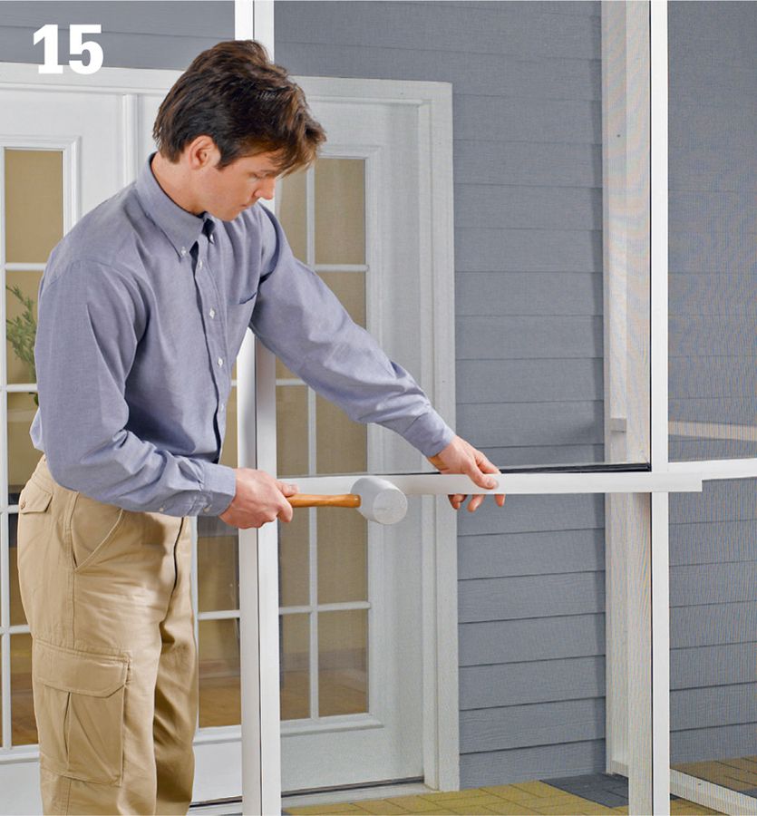
Install the horizontal pieces once the vertical cap pieces are in place using the same techniques. Butt the horizontals tight against the verticals to start each piece, and then trim it to length as you approach the opposite end.
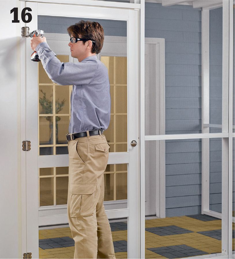
Complete the screening project by installing a screen door. A low-maintenance vinyl door provides a good match with the finish of the vinyl trim cap, but a traditional painted wood door is also appropriate. See pages 226 to 227 for door installation steps.
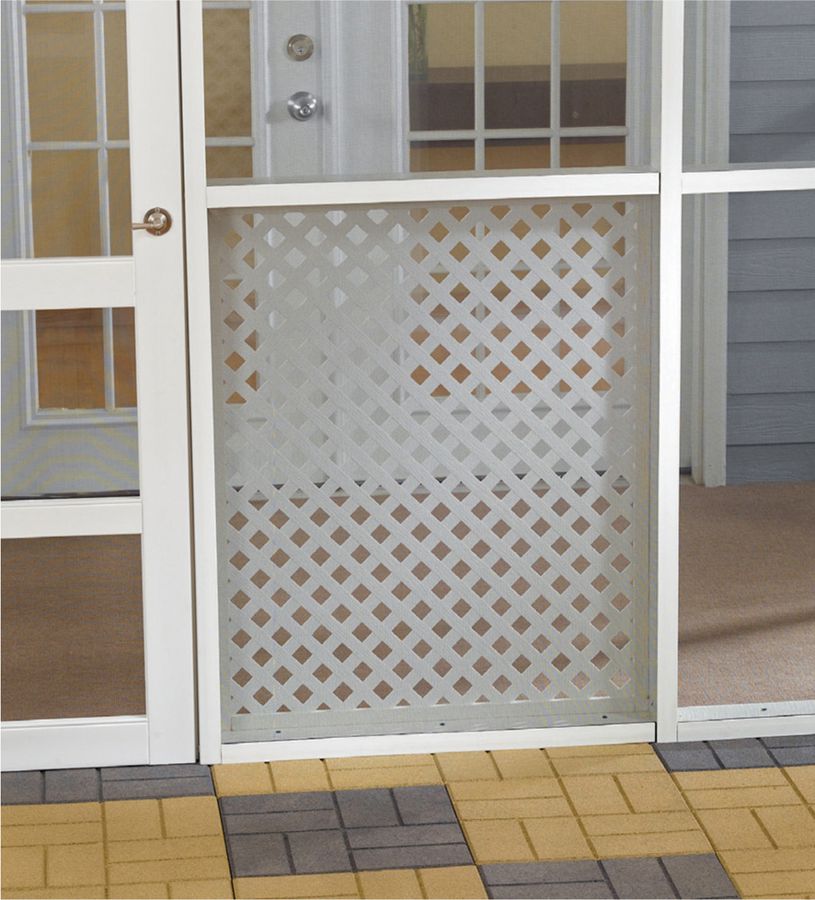
Option: To protect the screening from being damaged by pets, kids, or other causes, make lattice frames and install them in the framed areas.
 How to Install a Screen Door
Measure the door opening. The new screen door should be 1/4 to 3/8" narrower and 1/4 to 1/2" shorter than the opening. Plan to trim the door, if necessary, for proper clearance. Some vinyl doors should not be cut, while others may be cut only a limited amount. If the door is vinyl, check with the manufacturer.
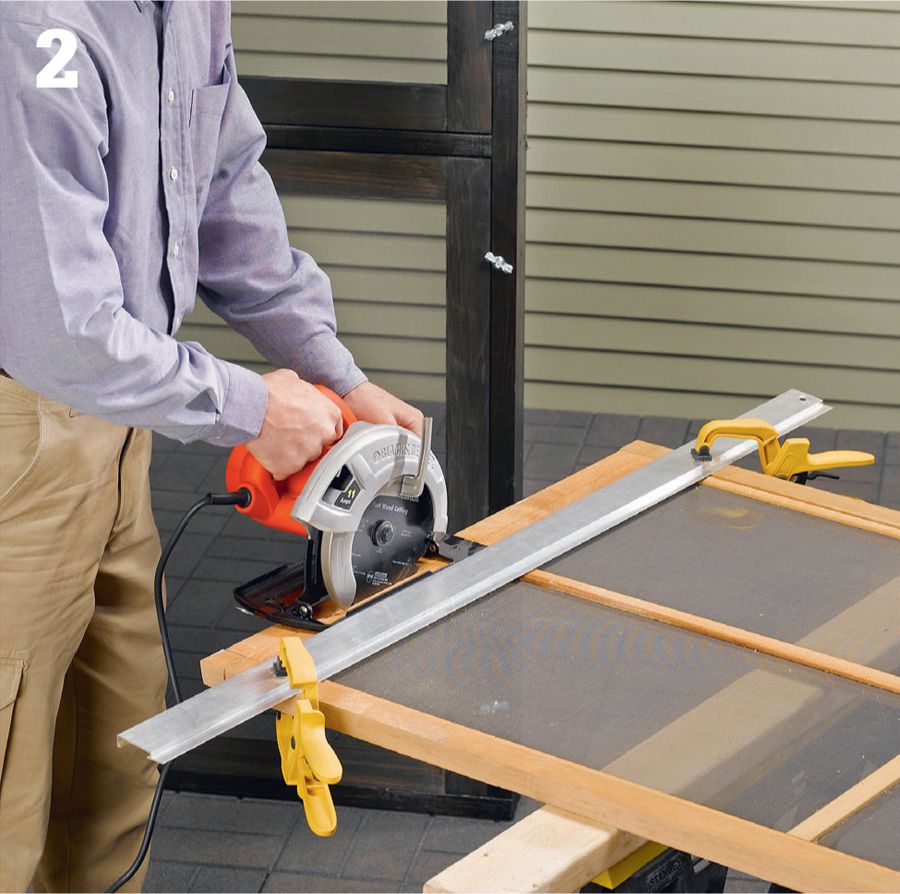
To trim the height of a door, mark the cutting line, then clamp a straightedge to the door to guide your circular saw for a straight cut. For wood doors, score deeply along the cutting line with a utility knife before setting up the straightedge; this prevents splintering on the top side when cutting across the grain.
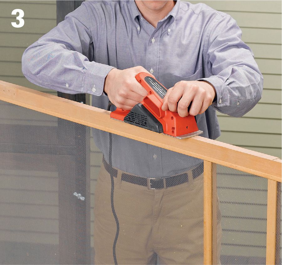
To trim the width of a wood door, it’s usually best to remove material from the hinge side, which is less visible. Mark a full-length cutting line, and make the cut with a circular saw. Or, you can use a power hand planer to trim off material from the edge (shown in photo). Use sand paper or a file to round-over the cut side (and bottom, if applicable) edges to match the uncut edges and to prevent splinters.
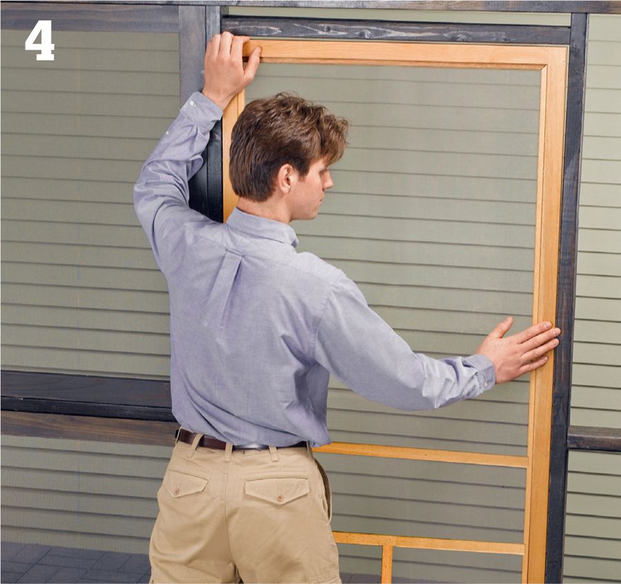
Test-fit the door in the opening using wood shims along the bottom to raise the door to the right height. Center the door from side to side; the reveal here should be about 1/8" on each side.
Install surface-mount hinges to the door using screws driven into pilot holes (three hinges is preferable, but two will work for most doors). Position the top hinge about 7" from the top of the door, the bottom hinge about 10" from the bottom, and the middle hinge halfway between the other two.
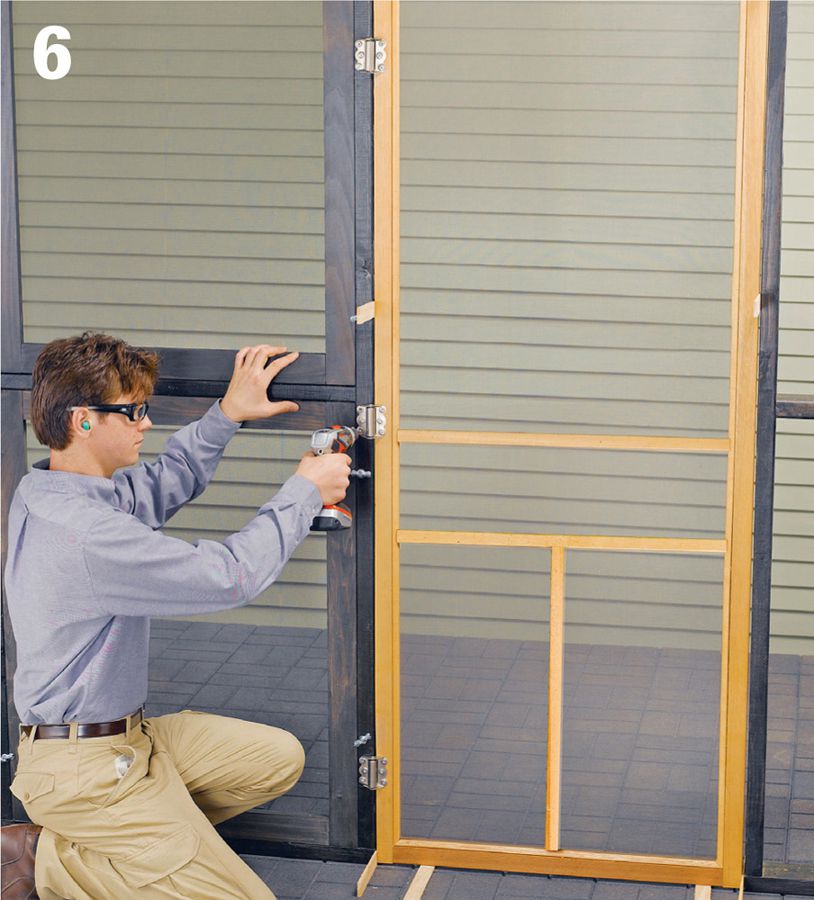
Hang the door. Set the door into the opening using shims at the sides to establish equal reveals. Mark and drill pilot holes for the hinges, then screw the hinges to the side jamb or post to hang the door.
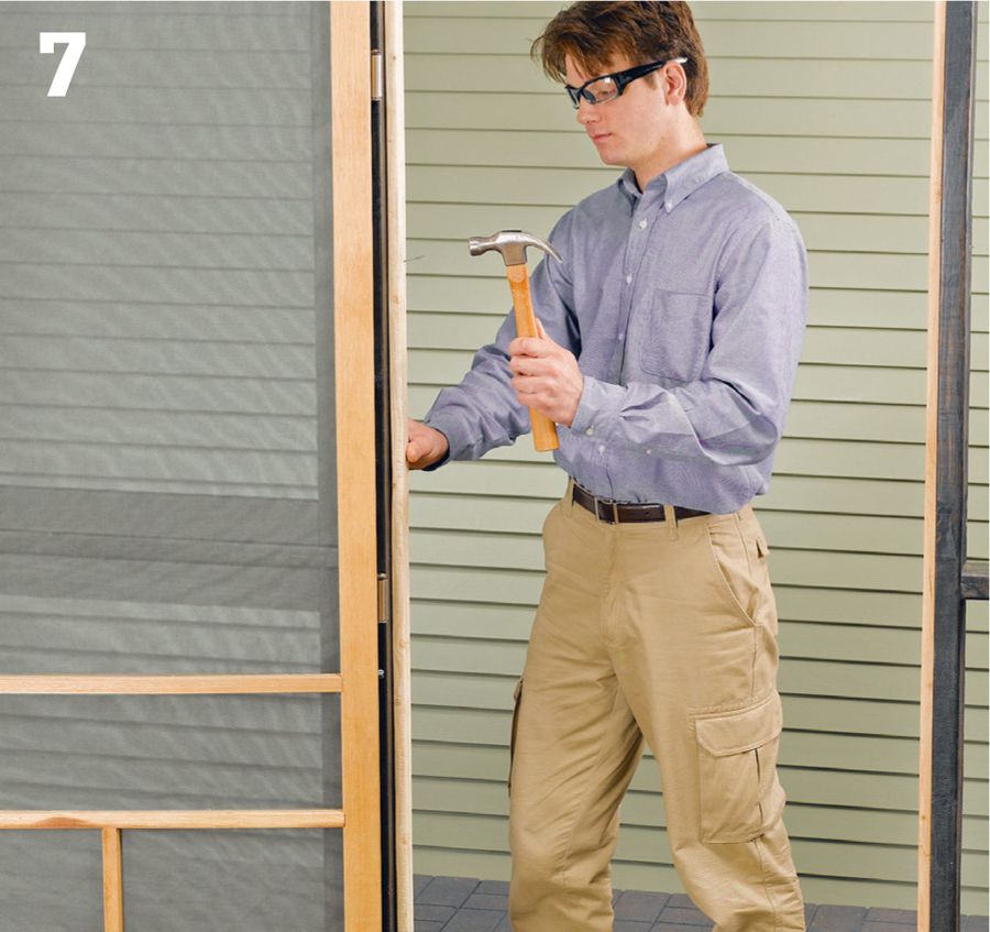
Install doorstop molding around the sides and top of the door opening using galvanized finish nails if your screen door is not prehung. Position the stops so the outer door face is flush with the outer jamb edges, trim, or door posts, as applicable. Install the stop along the top of the opening first, then along the sides.
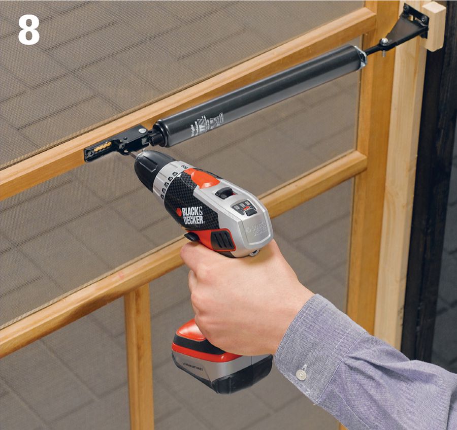
Add door handles, latches, and closer hardware as desired, following the manufacturer’s instructions. A closer is a good idea to prevent the door from being left open and admitting insects. Closers come in a range of types, including spring-loaded hinges, hydraulic pistons, and old-fashioned extension springs. Most also have a stop chain that prevents the door from blowing all the way open.
 Patio Kitchen
Loaded with convenient work surfaces and a dedicated grill space, the outdoor kitchen has changed backyard grilling forever. This roomy kitchen can be the perfect addition to any patio or garden retreat. It’s made entirely of concrete blocks and not only looks great, it’s also incredibly easy to build.
The design of this kitchen comes from a manufacturer that supplies all of the necessary masonry materials on two pallets. As shown, the project’s footprint is about 98 × 109 inches and includes a 58-inch-wide space for setting in a grill. Square columns can provide work surfaces on either side of the grill, so you’ll want to keep them conveniently close, but if you need a little more or a little less room for your grill, you can simply adjust the number of blocks that go into the front wall section enclosing the grill alcove.
Opposite the grill station is a 32-inch-tall countertop capped with large square pavers, or patio stones, for a finished look. This countertop has a lower surface for food prep and a higher surface for serving or dining. A low side wall connects the countertop with the grill area and adds just the right amount of enclosure to complete the kitchen space.
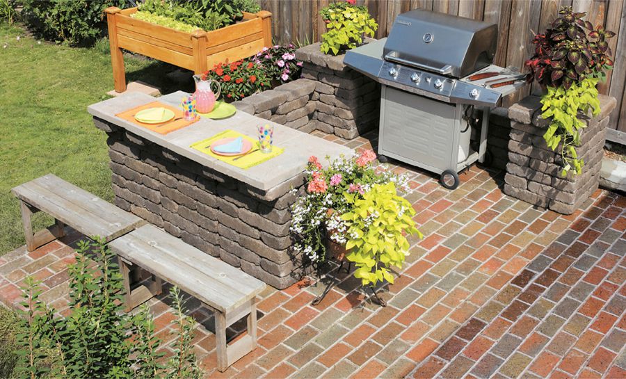
This all-masonry outdoor kitchen comes ready to assemble on any solid patio surface, or you can build it over a prepared gravel base anywhere in your landscape (check with the manufacturer for base requirements). For a custom design, similar materials are available to purchase separately and the installation would be more or less the same as shown here. Discuss the project with the manufacturer for specifics. If you decide to build just a part of this kitchen (the bar, for example), review the setup and site prep steps at the beginning of this project.
 How to Build a Patio Kitchen
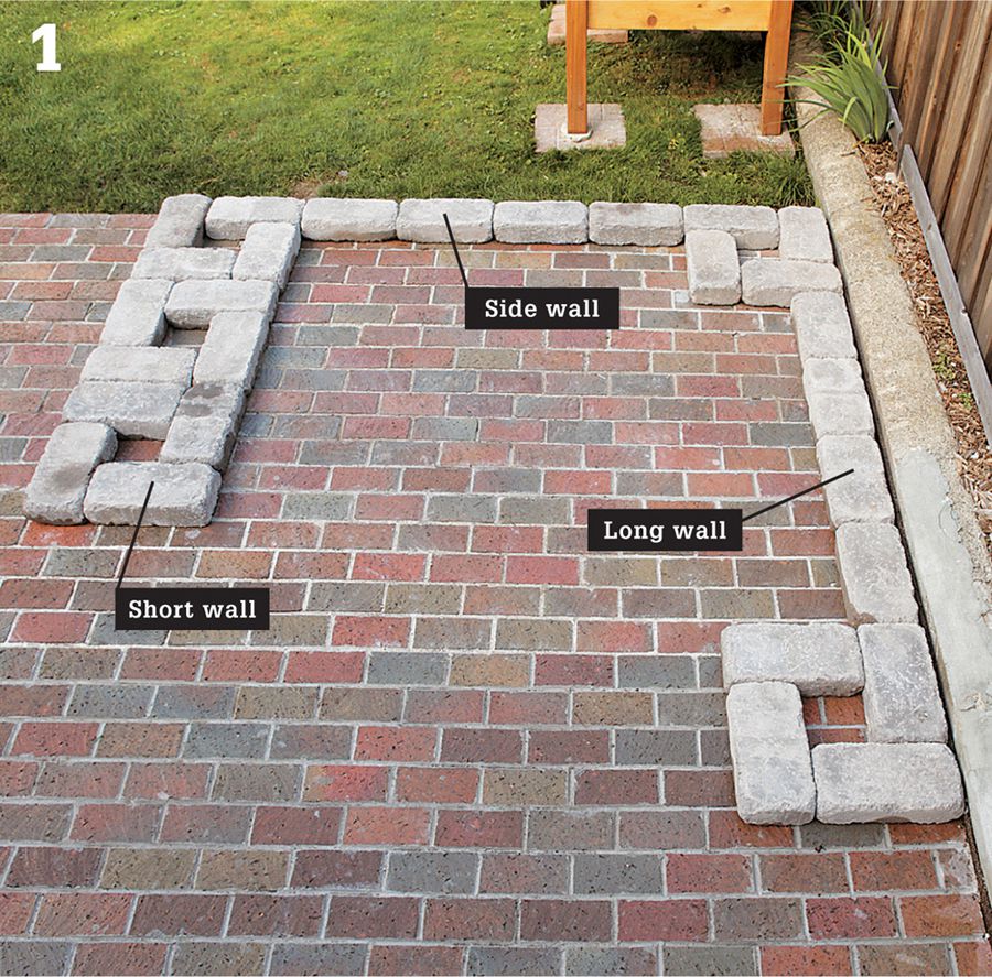
Dry-lay the project on the installation surface. This overview of the first course of blocks shows how the kitchen is constructed with five columns and two wall sections. Laying out the first course carefully and making sure the wall sections are square ensures the rest of the project will go smoothly.
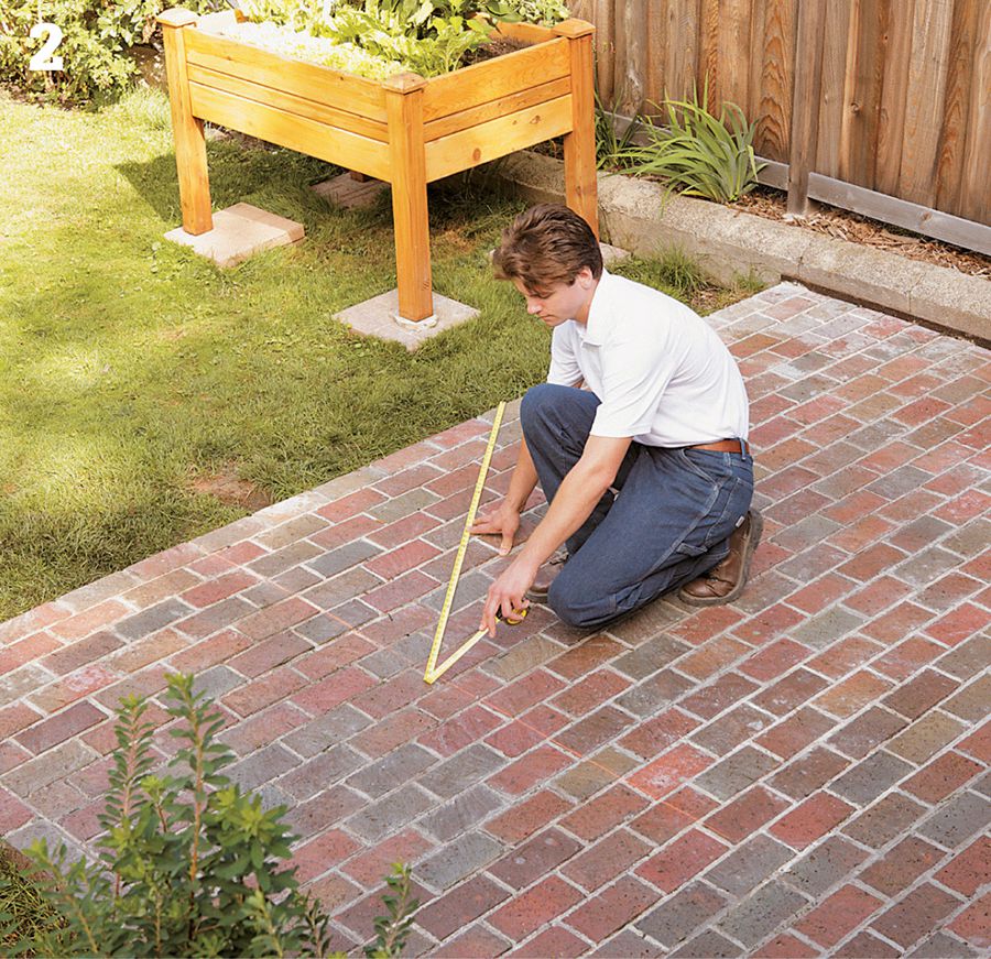
Create squared reference lines for the kitchen walls after you remove the dry-laid blocks. Snap a chalk line representing the outside face of the front wall. Mark the point where the side wall will meet the front wall. Place a framing square at the mark and trace a perpendicular line along the leg of the square. Snap a chalk line along the pencil line to represent the side wall, or use the edge of a patio as this boundary (as shown). To confirm that the lines are square, mark the front-wall line 36" from the corner and the side-wall line 48" from the corner. The distance between the marks should be 60". If not, re-snap one of the chalk lines until the measurements work out.
Begin laying the first course of block. Starting in the 90° corner of the chalk lines, set four blocks at right angles to begin the corner column. Make sure all blocks are placed together tightly. Set the long wall with blocks laid end to end, followed by another column.
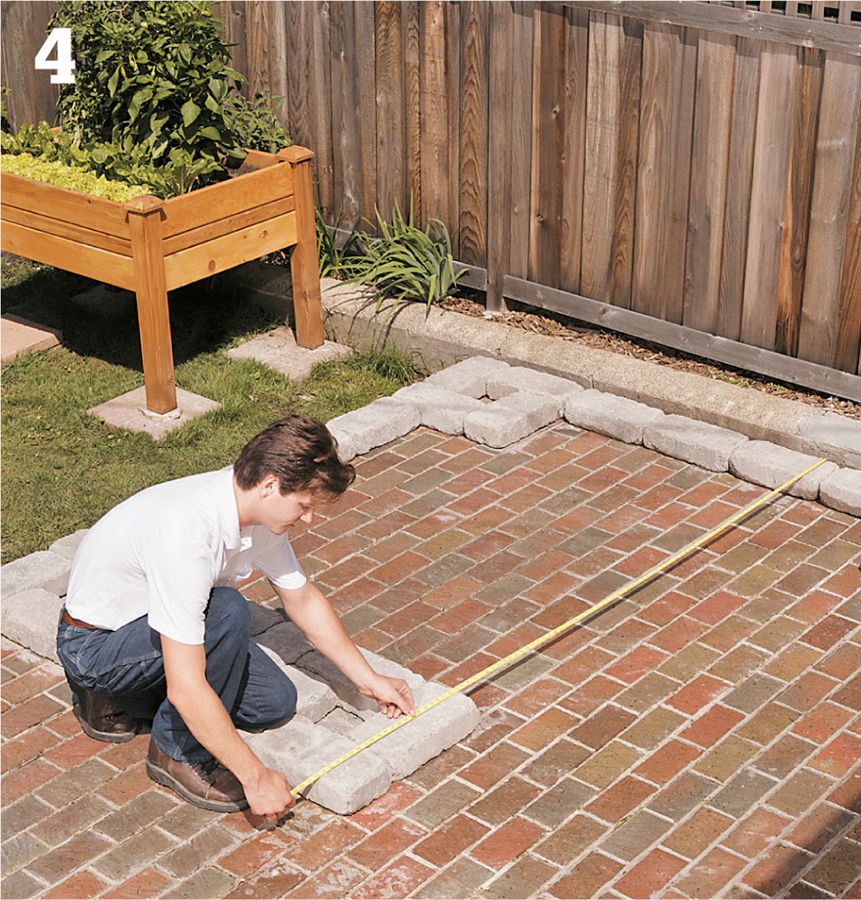
Finish laying the first course, including two more columns, starting at the side wall. Use a straight board as a guide to make sure the columns form a straight line. To check for square, measure between the long wall and the short wall at both ends; the measurements should be equal. Adjust the short-wall columns as needed.
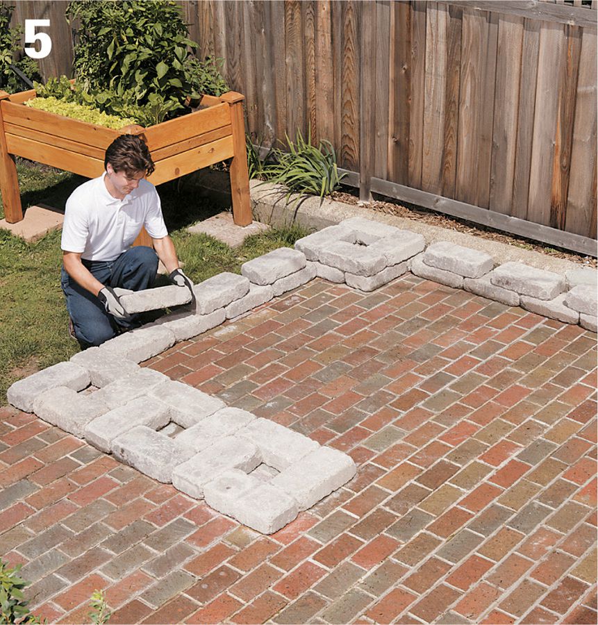
Set the second course. Add the second course of blocks to each of the columns, rotating the pattern 90° to the first course. Set the blocks for the long and side walls, leaving about a 2" gap in between the corner column and the first block. Set the remaining wall blocks with the same gap so the blocks overlap the joints in the first course.
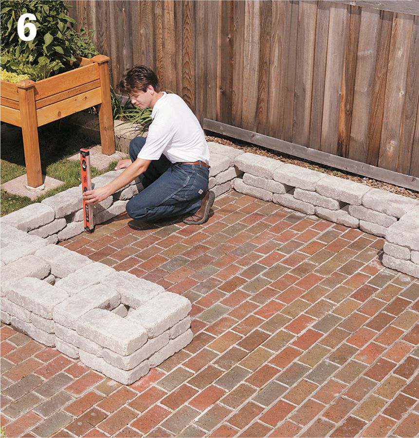
Set the third course. Lay the third-course blocks using the same pattern as in the first course. For appearance and stability, make sure the faces of the blocks are flush with one another and that the walls and columns are plumb. Use a level to align the blocks and check for plumb.
Install the remaining courses. The higher courses of wall block are glued in place. Set the courses in alternating patterns, as before, gluing each block in place with concrete adhesive.
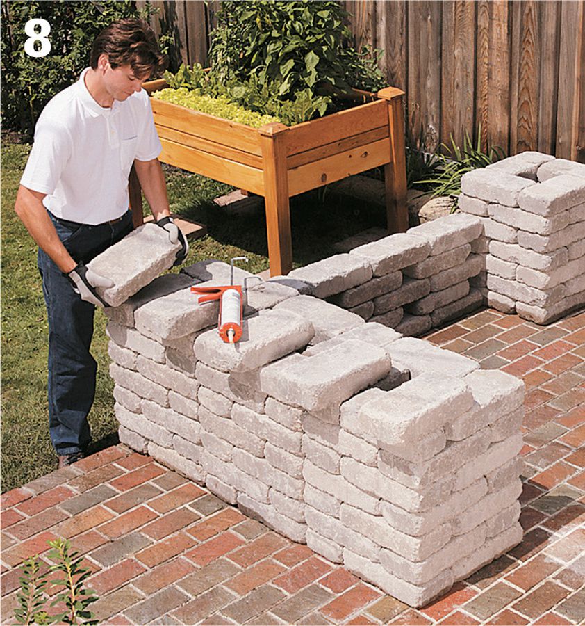
Build the short wall overhang. Starting at one end of the short wall, glue wall blocks along the tops of the columns with concrete adhesive. Position blocks perpendicular to the length of the short wall, overhanging the columns by 3".
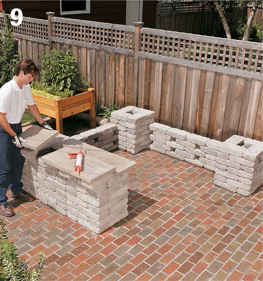
Complete the short wall top. Create the counter surface for the short wall by gluing patio stones to the tops of the columns and overhanging blocks. Position the stones for the lower surface against the ends of the overhanging blocks. Position the upper-surface stones so they extend beyond the overhanging blocks slightly on the outside ends and a little more so on the inside ends.
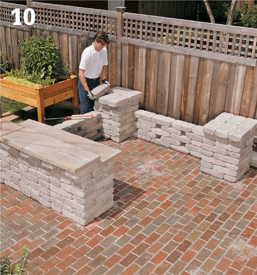
Cap the corner columns. Finish the two corner columns with wall blocks running parallel to the side wall. Glue the cap pieces in place on the colomns using concrete adhesive. Make sure the blocks are fitted tightly together.
 Shade Sails
Not too long ago, the only option for cooling a sun-scorched patio was an overhead structure like a pergola or arbor. Each required a serious superstructure, used a lot of lumber, and needed frequent maintenance. Shade sails offer a simpler approach. Made of high-density, UV-resistant polyethylene knit fabric, sails can be installed in a couple days, often at a lower cost than a lumber structure. Once installed, they offer respite from the sun, a jolt of color, and some cool aerial sculpture.
However, free-form as shade sails may appear, they require some serious planning. Begin by deciding on how many sails you want. A single triangular or rectangular shade sail may do the job. However, layering several sails boosts the shade area and lets you blend colors. There are few set rules to arranging sails. The primary goal is to achieve as much shade as possible throughout the day during the summer when you most want to enjoy your patio. Some homeowners make scaled-down foam core models to experiment with different sail combinations. (The angle of shade for the scaled down model is the same as that for the full versions.) Or, you can get expert advice—often worth the money. Some suppliers offer design services for a fee. They produce 3-D concept sketches that can be viewed using different date and time settings to accurately determine where the shade will fall each day of the season. Contractors often model the installation on a CAD (Computer Aided Design) program and then print out a series of 3-D renderings so you can see what the shade effect will be hour by hour.
Single shade sails are enough to add shade, color, and some aerial excitement. By varying the height of corners you achieve interesting shapes that maximize shade and shed water during rainstorms.
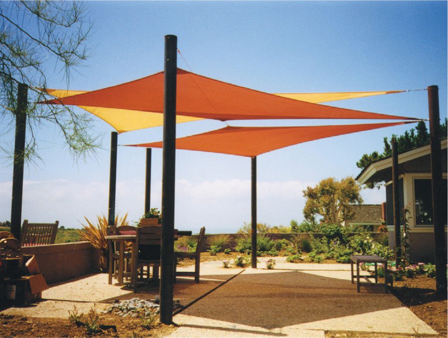
More than just shade, sails offer a stylish play of color over a patio. Being slightly translucent, the colors of the sails compound themselves. Many homeowners speak of enjoying the gentle breathing movement of the sails overhead.
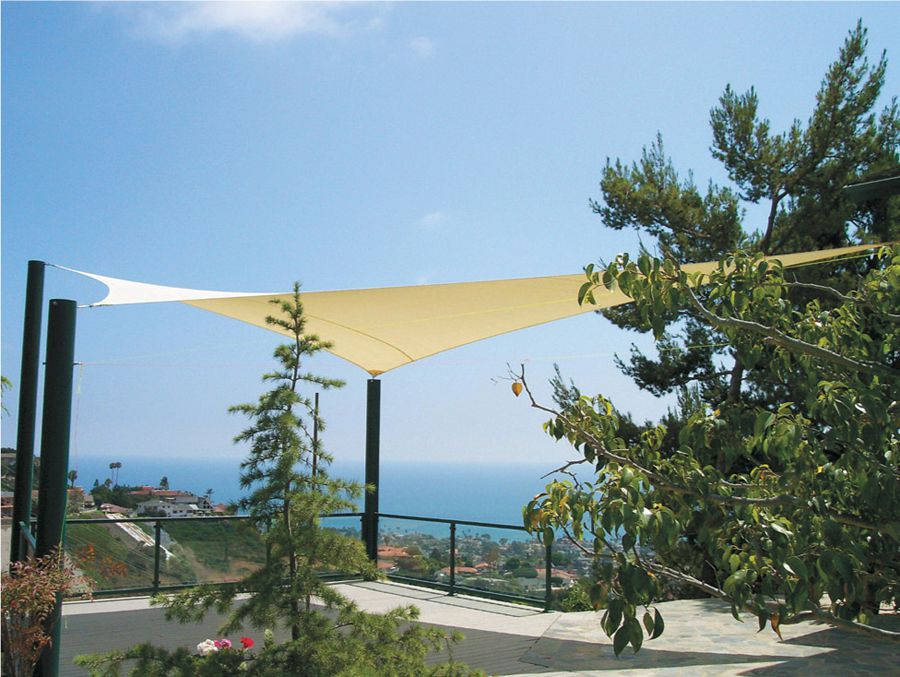
Because trees and a desperate need for shade tend not to go together, it is common that you need to set posts in concrete or take other steps to create your own attachment points for the shade sail stays.
Sails carry serious wind loads and create lift much like an airplane wing. That’s why strong posts are critical. For small sails 4 × 4s will serve, but go with something stronger for heavy winds. The safest choice for any size sail is 4-inch “Schedule 40” steel pipe set one third of its height in the ground. Because the sails move gently up and down in the wind, mount the sails 18 to 24 inches apart.
What you use to mount the sails is critical as well. Use only stainless steel hardware—it is pricey (for example, a turnbuckle may cost $22 and up) but is exceptionally strong and won’t rust. Make sure the lag screws for mounting brackets pierce framing members, not just siding or fascia. You’re on firm ground if you attach a bracket to the corner of the house—there is always substantial framing there. Elsewhere, a stud finder (available at any home center) will help you find the framing members. A web search of the many shade sail suppliers will yield hardware to suit most any situation you run into.