Chapter 9
Welding of Steel Mechanical Components 1
9.1. Introduction
This chapter presents the main techniques of welding steel mechanical components using examples from the automotive industry — apart from body panels — and discusses the specific weldability limits due to functional needs and mass production.
To determine these needs, they may be helpfully compared with those of steel construction (see Chapter 10). The latter relates especially to a single construction or to a limited set, and requires easy assembly and relatively crude joints in terms of positioning and finished aspect. It is in this context that welding has, for example, replaced the riveting of railway station beams or plates for ship-building, etc. Moreover, elastic strain limits (a beam’s sag limit for example) need specific geometries (moments of inertia) and generally these limits come into play before the strength limitations at the critical bond zones.
For mechanical components, the fatigue performance to weight ratio is often of paramount importance and requires demanding mechanical characteristics which are possible only with alloyed steels and are therefore not easily weldable.
Moreover, mechanical components generally have specific service requirements:
– geometric precision: as an example, many parameters which characterize gear teeth are measured in micrometers,
– wear resistance and tribology of friction surfaces justifies a very exacting surface condition: roughness, Hertzian pressures, coatings, physico-chemical endurance,
– pitting resistance in certain contact zones,
– various types of fatigue performance: contact, notch, corrosion, etc.
For all these reasons, the steels used for mechanical parts are often treated to strength levels higher than 1,000 MPa, and the corresponding assemblies generally must:
– be welded with a high degree of accuracy in their relative positioning,
– have their mechanical properties lightly down graded especially in restricted loading areas,
– be able to undergo heat treatments or complementary finishing processes.
These stipulations must obviously be modulated according to the type of component concerned. In the automotive industry, for example, the welding requirements are different for suspension components and mechanical parts.
External components, like subframes and suspension assemblies, are generally manufactured in low alloyed steels, with rather low carbon-manganese contents (less than 0.2% C, 1% Mn), often without any finishing treatment. These parts are spot welded (for thin sheets) or with a weld bead, without significant metallurgical problems.
Mechanical parts, as in the power unit or transmission, on the other hand, are manufactured in steels whose composition and heat treatments are especially adjusted to the properties required by use. In automatic gear box manufacture, for example, mild steels locally nitrided in the friction areas are often used for housings, but also mid-carbon steels (i.e. XC 42 grade) subject to local induction hardening, as well as more alloyed nitriding steels for the most severely frictioned parts. As for bending and spalling performances at the tooth root, they can be satisfied by fairly shallow carbo-nitriding and steel alloys such as 27 Mn Cr 5 or 30 Cr Mo 4 for current automotive requirements, although deeper thermochemical treatments and higher alloyed steels are obviously needed for truck pinions. At the very extreme, bearing components are generally manufactured in the emblematic 100 Cr 6 grade without any possibility of welding!
The criteria to evaluate operational weldability depends on the components under consideration, in particular the possible extent of the joint’s remolten zone. As long as the latter requires a filler or several passes and remains relatively large (in the order of what was presented for steel construction), the majority of the quite restrictive metallurgical and mechanical considerations (carbon equivalent, clamping constraints, hydrogen, etc.) which have been set out in the previous chapters remain applicable. On the other hand, more severe tolerances are required the narrower the remolten zone is (high energy beams), and these tolerances may be completely reduced in some contact joining (friction welding, electrical resistance welding, or diffusion welding in the solid phase).
In this presentation, the adaptation of arc welding conditions to alloyed steels [CAZ] and the metallurgy of the welded joint [AWS, GRA] will only be outlined briefly. We will concentrate on the possibilities of limited fusion processes used in welding operations for the mass production of mechanical components. We will show that the mass production requirements for mechanical construction need robotized welding processes, compatible with cycle times and control procedures on the assembly line.
This chapter will proceed via the following technical items:
– bond specificity requirements, operational standards and the weldability of alloyed steels used in mechanical components;
– main types of welding processes used for mechanical components and examples of these processes in automotive engineering;
– specifications and quality control of the welds for these parts;
– developments and tendencies with regards to mechanical component welding.
9.2. Specificities of welded bonds in mechanical components
9.2.1. Standard welding processes and general recommendations
Spot welding is the rule for the assembly of thin mild steel sheets in body panels because the sheet clamping and the robotization of spot welding have for some time now operated with a widely recognized productivity and ease of use.
For mechanical components, previous manufacturing practises, which used to aggregate the functional surfaces into fewer sub-parts more or less easy to assembly, seldom encouraged welding.
However, the development range of these parts results from many feasibility and cost factors (ease of machining, assembly, treatment, etc.) in which the opportunity of welding compared to other modes of joining is not always decisive.
Initially, some thermal or mechanical fretting can prove sufficient, either alone or with complementary safety adjuvants like adhesive bonding, keying, pinning or extra spot welding. For the components which need a complementary thermochemical treatment, it is necessary to grind or hone surfaces and delayed failures may be expected in areas with residual stresses.
In some other cases, a traditional assembly by screwing or bolting offers an accurate enough connection without altering the properties of the finished components. An additional “disassembly capability” is thus ensured with limited extra machining and assembly costs.
Without any need for future disassembly, maintenance or exchange, the welding operation may be attractive from the perspective of the assembled parts. As for the process, it allows savings in cycle time, space or assembly personnel and manufacturing cost, especially if it is carried out on robotized multipost machines combining positioning, welding and possibly a stress relief process in less than one minute. This technology is used widely in the assembly of components such as automatic gear boxes, where steel shafts or low alloyed flanges must be solidly connected — with minimal dimensional obstruction — to clutch housings made of extra soft steel.
On the other hand, the risks of initial damage by cold cracking remain significant for the various forms of arc welding as soon as the carbon equivalent of the molten metal (dependent on the component parts’ composition and that of a possible filler) exceeds 0.47% [AWS, GRA 95] and that the choice of the base metal cannot be modified. An adapted pre-heating, or even a post-heating treatment, may then become essential, according to geometric and thermal parameters of the assembled parts. Brazing can also be a viable option if the assembly is not subjected to excessive loads or if the surface area to be brazed is large enough (with the possible addition of grooves) to spread the static and dynamic loading.
Good part design can contribute to limiting the load a weld is subjected to, or to reducing the functional consequences of a particular assembly configuration. Consequently, a laser beam welding with a precise positioning may be satisfactory, for example because otherwise the assembled part would involve an overly complex or badly stressed geometry.
For some axisymmetric parts like bimetallic valves, high speed friction welding, with subsequent work on the bead, but often without any post treatment, fully justifies the material cost benefit on the component part.
Lastly, for most highly loaded parts, the alteration of mechanical properties after the welding operation is not a problem insofar as the heat treatments required to achieve the properties demanded by future use are generally carried out after the welding operation. Nevertheless, it is necessary to avoid unacceptable bead defects: porosities and notch factors at weld root for fatigue or shock problems [LIE 82, DER 81].
Some technological recommendations are essential, as for any welding operation:
– in the joint design, it is essential to balance the masses on both sides, and to avoid any weak zones (small section, sharp angle) close to the weld;
– an axial weld has the tendency, unless clamped, to splay out the lightest part, while a radial welding involves a skewed setting. The insertion of one part in another instead of a gap between parts reduces these defects;
– a radial weld is preferable to an axial weld in cases of a difficult material or deformation;
– the permissible gap in the mating plane, established according to the machining tolerances, the positioning gap and the perpendicularity of the faces to be joined compared to their axis must be limited to 0.10 mm;
– the surface finish of the mating edges is limited to 10 µm, and burrs are generally prohibited on these faces;
– it is essential to remove any trace of rust and grease, and to dry the parts after washing.
These inexhaustive recommendations concerning the connection, are derived from experience and are fairly independent of the metallurgical factors affecting joint strength.
9.2.2. Metallurgical defects in the molten zone and the HAZ
The various possible defects in the welds may be classified into two main categories:
– technological defects such as those operating upon geometric matching, or the lack of fusion,
– metallurgical defects such as inclusions, porosities, cracks.
In fact, the metallurgical health of the welded joint depends firstly on a good choice of technological parameters: geometry and joint preparation, welding mode, linear energy input and welding speed, parameters of pre- and post-heating. The molten zone and HAZ are critical areas because of their sensitivity to internal defects, inappropriate metallurgical structures and unfavorable residual stresses.
Furthermore, defects can reduce the cross section of the joint and give rise to stress concentrations which can lead to local failure at unexpected loads.
9.2.2.1. Defects in the molten zone
The most common defects in the molten zone after welding are:
– porosities due to dissolved gases either trapped during solidification or coming from chemical reactions in the molten metal;
– lack of penetration at the connection or between two successive beads;
– hot or cold cracking, in the sensitive structures, in areas with high tensile (transitory or permanent) stresses.
The superposition of a residual stress field to the applied stresses can reduce the service load of a defective welded joint still further.
Steelmaking conditions (deoxidation, sulfides, residual nitrogen content) may affect the risk of porosity and the bead shape (wetting capacity of the molten metal), but the main issues are related to the risk of cracking because of an unsuitable choice of operational parameters.
Arc welding, with rather high filler metal content and remelting, can lead to geometric defects (acute angled connections, lack of penetration), metallurgical defects (cracks) or enhanced latent defects (tearing on large inclusions).
Geometric defects mainly concern the positioning of surfaces to be welded and the operational practise. The weld depth may be a problem, in particular for weldings by high density energy beams — of the laser type — for which it is difficult to exceed 10 mm of steel with nominal outputs up to 10 kW.
However, mass produced mechanical components generally have limited dimensions, are the subject of careful ranges of preparation, with automated welding processes, which are therefore very reproducible.
9.2.2.2. Various types of cracking
Among the metallurgical risks of cracking, hot cracking may arise, related to the particular compositions of the molten metal (for example, sulfur or lead content higher than 0.025% to improve workability), and worsened by a poor weld bead configuration. Cracking by lamellar tearing because of poor ductility levels in the through direction remains unusual in mechanical components judiciously welded in series after a whole range of validation tests.
Obviously, cold cracking in the HAZ associated with coarse hardened structures, residual tensile stresses and hydrogen traces remains the most significant obstacle to welding with large remelting zones in structural steels.
As for alloyed steels, cracks are the most frequent metallurgical defects: hot cracking in the melted zone, cold cracking in the HAZ, cracking on reheating:
– Hot cracking: this especially affects steels presenting an austenitic solidification. It results from the rejection of sulfur and phosphorus with a corresponding lowering of the solidus. The stresses at the end of bead solidification can then occasion tears at the location of the last liquid zones. This justifies content limitations for critical elements in fusion welded metals, of the type S + P <0.04%.
– Cold cracking: the conditions of hydrogen embrittlement (residual tensile stresses) are found in the HAZ as well as in the molten metal, because the latter is richer in hydrogen even with a more dilute composition than the HAZ. A sensitivity estimate of welded steels can be established from the various traditional formulae for carbon equivalent percentage, of the type Ce = C + Mn/6 + (Cr + Mo + V)/5 + (Cu + Ni)/15, etc. [DEB 84]. The significant influence of cleanliness, not taken into account in this type of formula, involves a recommendation of low impurity contents (S, P, Sn, As, Sb) in the case of difficult weldings. For sulfur, there are also risks of lamellar tearing which require the simultaneous control of sulfide content and morphology (necking through fibers); for example, sulfur is limited to 0.025% for automotive mechanical components.
– Reheat cracking: this is sometimes reported in the case of low alloyed steels for pressure vessels and poorly stabilized stainless steels. This is a case of intergranular crackings which can appear during post-heating, because of intergranular carbide precipitations and impurities.
In addition to the cracking risks, the required service properties of welded steels may impose particular demands on the welded zone: creep resistance for pressure apparatus in hot working conditions, fatigue strength in particular conditions, resistance to the various types of stress corrosion, etc. The intergranular chromium carbide precipitation in the HAZ during a welding cycle can compromise, for example, the tensile corrosion behavior of a stainless steel.
Lastly, welding on an already treated zone can involve cracking, because of the localization of strong residual stresses (for example, on an induction hardened part) or of dangerous alloying (thermo-chemically treated parts). In the latter case, it is better to spare the zone which will be welded from thermochemical treatment or subsequent machining (grinding).
9.2.3. Weldabiity limits for welding with and without remelting
The metallurgical difficulties for welding result from the structural reactions of welded metals to the particular thermal cycles of the operation.
9.2.3.1. Principal consequences of a significant remelting
In case of remelting, solidification shrinking initially occurs in the melted zone, a function of the solidification interval of the metal, and in fact a mixture of the welded metal and the filler. The size of the molten zone, the shrinkage rate and the rheological behavior of metal during cooling governs the distribution of the residual stresses in the welded zone.
In general, the thermomechanical welding effects (solidification shrinkage in the melted zone, dilatations and strains during allotropic transformations, residual stress extensions) depend on the welding mode, the geometry of the joint and the metallurgical behavior of metal.
This behavior is obviously varied for alloyed steels, due to many various heat treatments: solution heat treatment, transformation and precipitation kinetics on cooling, precipitations during post-heating.
The prediction of this behavior requires the assimilation of the phase diagrams (for example, the Schaeffler diagram for stainless steels) and the continuous cooling transformation diagrams after special austenitization conditions prevalent in the HAZ (with particular carbide solubility and grain size). These effects, which have a great influence on the internal integrity and the service properties of the welds, have been the subject of quite complex software simulations (a well known example is SYSWELD). Often it is only necessary, for each type of welding and joint geometry, to refer to thermal data charts, which make it possible to visualize the cycles at the most critical points of the HAZ (see Chapter 3). Having considered the appropriate steel transformation diagrams, the evolution of the structures and their properties can be easily forecast.
It is very useful to reduce the extension of the melted zone as far as possible, in order to reduce the probability of bead defects, hydrogen embrittlement, the extent and danger of coarse grain martensite in the HAZ, damaging residual stresses, etc. From this point of view, raising the power of the thermal source is advantageous since it increases the thermal gradients (Fourier’s law). In an extreme case, friction welding without remelting allows the joining, without any complementary tempering, of bimetallic exhaust valves, a part of which is made of martensitic stainless steel of grade Z 45 Cr Si 9.
Even if it is difficult to avoid remelting and the concomitant risks of hydrogen embrittlement (only one ppm is already too much…), the brittleness of the out of equilibrium structures resulting from the reaustenitized coarse grain areas remains a problem.
Taking into account the relatively high hardenability of the steels used in mechanical parts, it is often difficult to slow down cooling at the end of welding and thus avoid martensitic structures whose hardness, brittleness and sensitivity to hydrogen traces increase with the localized carbon content. The brittleness of some higher carbon bainites or of some austeno-martensitic aggregates can be also a problem (see the example of steel grade 15 Cr Mo V6).
9.2.3.2. De-embrittlement of the HAZ
Tempering treatments after welding have two specific functions, often optimized in an independent way: relieving residual stresses and/or reducing brittleness from quenched metallurgical structures.
As soon as the steel composition precludes any possibility of achieving microstructures less sensitive to hydrogen while exploiting welding parameters, it is necessary either to reduce the harmfulness of hydrogen by pre-heating or to promote the diffusion of this gas out of the welded zone by post-heating (generally with a higher temperature than that of pre-heating).
Pre-heating has the main effect of reducing the cooling speed after welding and incidentally lengthening the time of hydrogen desorption on cooling, while post-heating performs only the latter function. The temperature-time cycle of post-heating is defined by a crack curve established from implant tests and leads to the concept of critical post-heating temperature for given welding conditions and material compositions.
In multipass welding, the critical post-heating temperature obviously also corresponds to the minimal temperature to be maintained between passes and after the last pass.
To avoid cold cracking on welded parts particularly high in carbon, it is sometimes possible to use an austenitic filler (often an austenitic stainless steel): if dilution makes it possible to preserve an austenitic structure after cooling to room temperature, it is not prone to brittle fracture, therefore to cold cracking. Moreover, hydrogen is relatively soluble in austenite, which contributes to trapping it in the molten zone and to avoid cracking in the HAZ. However, it is necessary to accept the brittleness of the martensitic HAZ and the low mechanical characteristics of the molten metal.
In the case of stainless steel components, some grades to be welded (for example: exhaust pipes) require care in their composition such as stabilization of titanium or niobium: the trapping of carbon, from the very manufacture of the raw material in very stable carbides, avoids the precipitation of chromium and the loss of the stainless character — while contributing to the control of the grain size — in the HAZ. The welding of heterogenous assemblies such as stainless + low alloyed steels requires some precautions [FAB 83]: precautions in respect of the molten metal, the heterogenity of the molten zone after dilution and microstructural instability in service. For austenitic steels, a hyper-quench under conditions close to delivery treatment makes it possible to simultaneously achieve a stress relieved, fine grained, and stainless metal.
9.2.3.3. Welding without remelting
The following characteristics can be expected from this process:
– the absence of porosity defects, shrinkage pipes or gaseous desorptions related to the difference in solubility of the gases (H, N, O) between liquid and solid phase,
– less shrinkage stresses,
– less coarse and brittle structures.
On the other hand, the problems of geometric matching and putting the surfaces to be welded into close contact are more critical, and require better surface preparation, as well as a minimum interfacial work hardening [HOU 91].
During the minute long formation of diffusion welded joints, the mechanisms of recrystallization after interfacial work hardening contribute to eliminate the initial interface, but at a micrometric scale. In fact, the mean free diffusion path during one second in iron austenitic state is only about one micrometer at 1,400°C, so the micrographic observations of grain boundaries crossing the prior interface are related to heterogenous austenite recrystallization with pinned grain boundaries on inclusions.
As no reflection echo can be detected on the interface, when an ultrasonic survey is carried out at wavelengths in the steel around 10 micrometers, it is possible in theory to guarantee the absence of micrometric defects on this surface. On such a scale the echoes corresponding to inclusions also appear.
9.3. Principal types of welding for mechanical components
Various thermal sources offer realistic means to obtain strong joints in less than one minute on decimetric components.
Most traditional is the electric fusion arc. Melting allows the connection and filling of the machined joint. The volume of the molten metal can be increased by an external contribution: arc welding with coated electrodes, MIG (metal inert gas) or TIG (tungsten inert gas) shielded welding. This molten base metal contribution is sometimes impossible, as in electron beam welding. However, it can be carried out using a coating metal whose melting point is lower than that of the base metal which is not melted.
In the case of brazing, it is the wetting process which ensures the connection and the continuity of very close surfaces, whereas there is the filling of a wide joint by the filler metal in the case of braze welding. We shall deal with these two last techniques very briefly in this chapter.
The very close solid-solid contact of two clean metallic surfaces can also ensure connection and continuity: this intimate matching can be the result of a plastic deformation under mechanical pressure and of a rise in temperature supporting interdiffusion and interfacial recrystallization (friction welding, resistance welding).
Sometimes, a fugitive melted phase appears, but it is quickly expelled (as in the case for spark welding).
Lastly, friction welding relies upon fusion, just like explosion welding or ultrasound welding.
The most frequent classifications of these various processes are based on the nature of the energy supply and the protection mode of metal brought to high temperatures (slag, inert gas, or vacuum). However, our presentation will adopt the decreasing order of the lineic powers used, or better still the relative size of the molten zone. For a specific introduction to welding of various mechanical components, the following order will be used:
– electric arc welding and its derivatives,
– welding with narrow high energy beams (laser, electron beam, plasma),
– friction welding (in solid phase with limited intrusion of molten areas),
– butt welding by the Joule effect (with creep and no significant remelting),
– diffusion welding in solid phase (not yet on industrial scale).
9.3.1. Electric arc welding and alternatives [CAZ 95, COL 83]
9.3.1.1. Various categories
One of the oldest forms of welding is manual welding with a coated electrode, employed for prototypes or small runs with parts of limited size. The filler material consists of a fusible powder coated metallic rod which, upon melting, contributes to the extent of the molten metal and protective slag. Obviously, this technique is not compatible with mass produced automated welds in the automobile industry.
The submerged arc process under a powdered flux is especially used in automated procedures for welding of significant thicknesses in boiler manufacturing or some other mechanized weldings.
The MIG/MAG processes, with a consumable wire electrode from a spool and gas protection, are useful in terms of flexibility and productivity [BOU 89]. The TIG process, with a refractory tungsten electrode and inert gas protection, is primarily used for stainless steels with a particularly good final purity of the molten zone.
As for the welding of structural steels, the welding parameters (equivalent energy, speed, temperature of possible pre-heating) are adjusted from data charts of the type presented in Chapter 3.
For safety components like suspension parts or those transmitting engine torque towards the wheels, the weld beads are always ground to avoid notch effects. Some stress relief tempering is carried out to eliminate the risk of delayed failure, and each series of parts is metallurgically checked by sampling. Various non-destructive testings on the production line are systematic for that kind of part: magnetoscopy for emerging defects, and also radiographic or ultrasonic checks to detect major porosities. For mass production runs in the car sector, controls are especially implemented at the validation stage for that component range (see section 9.4).
To complement bead finishing, a pre-stress shot-blasting is frequently carried out on the welds in order to subject the zones in which fatigue cracks could occur to compression. Operations of scouring-passivation on stainless welds make it possible to standardize corrosion performance of the parts.
9.3.1.2. An example: arc welding of the drive shaft and housing
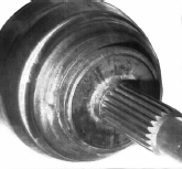
The drive spindle and housing (see Figure 9.1) is the outer component of the CV joint taking the role of a stub axle, driven by the half shaft.
The CV housing is made from low carbon steel hardened by precipitation (HES 400), the splined shaft in XC 42 allowing a later induction hardening of the splines and the bearing surfaces.
The arc welding of the shaft to the CV housing is carried out on a machine with a rotary table and automatic loading of the housings and shafts. The operation is carried out in two stations: vertically, in a turning chuck, with filler wire delivered from a coil; and under a protective gas (92% argon + 8% CO) delivered at a pressure of 3 bars.
After welding, an interior brushing of the housing is carried out to eliminate burrs, then the parts are removed to cool down naturally. The filler wire (GS2) 1 mm in diameter and with a coating of 2 µm is uncoiled at 15 m/mn during welding, while the circumferential chuck speed is 0.8 m/mn. The electric welding parameters are the following: 295 A, 31 V. The time cycle is 0.26 mn, which corresponds to a daily production of 12,000 units. The “fresh” welding, as well as the base of the housing treated by induction, are subjected on line to a tempering process with a peak temperature of 275-300°C controlled by IR pyrometers. A 100% check of the housing to shaft connection is carried out by ultrasonic checks.
9.3.2. Welds with reduced HAZ using high density energy sources: laser beam, EB, plasma
9.3.2.1. Various categories
To decrease the volume affected by residual stresses, it is helpful to reduce the melted thickness by the use of concentrated high density energy beams as the thermal gradients from the surface are proportional to the incident flux.
The fast developing process is a laser beam [BOU 92, CAZ 94, COL 83, MAZ 82] taking into account its convenience in use and the availability of ever more economic sources in terms of capital investment and maintenance costs.
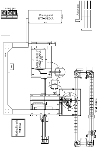
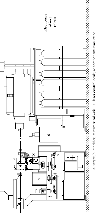
For example, an automatic gear box manufacturing facility in the north of France achieves, for a recent gearbox, ten laser welds on a torque converter and mechanisms thanks to five 6 kW sources (high frequency excitation lasers), each one operating at rates of 200 parts per hour.
In Figures 9.2a and 9.2b a horizontal and side elevation of this installation are presented.
In the latest flat laser source configurations (slab), the optical resonator is positioned between the two mirrors and the two parallel radio frequency electrodes: as the heat of the excited gas is dissipated in these two water-cooled electrodes, the traditional systems of gas circulation are no longer necessary, which leads to lower overall dimensions, low gas consumption and improved performance with lower energy and maintenance costs.
Typically, a CO2 laser with an effective 6 kW power output costs around €4.105. To put a coarse price on such laser weldings, we can imagine an automated installation of two transverse flux lasers of this type, consuming 120 kW, and a weld rate of 200 parts per hour (the size of automatic gearbox components, for example): the total cost price (technical costs + indirect costs + depreciation) of the integrated operation is less than €0.5 per component
CO2 lasers operating at a 10.6 µm wavelength remain the most widely used for their high power output (up to several kW), although YAG or laser diode batteries with a wavelength close to one micrometer have better absorption characteristics and can use fiber optics as a waveguide. Laser diodes are becoming increasingly popular, with output powers close to one kW, and welding robots to weld small runs of various components (see section 9.5).
Laser has limitations in the thicknesses it can weld and the depth penetration of the beam is typically less than 10 mm. Its field of use is still very broad for mechanized welded construction where subsidiary binding parts have to be welded to the main structure (for example: pins, lugs, drive forks, etc.). These weldings can undergo dangerous notch factors at the surface of the molten zone, especially for low toughness special steels (K1c <50 MPa  ), and these risks can be avoided by pre or post-passage of a defocalized beam.
Electron beam welding is widely used industrially in boiler operations for the petrochemical industry or for nuclear power plants. In that context, welding concerns specific alloyed steel grades and thick plates. The advantages inherent in the process are the following [BOU 95, GRA 81, VAL 83]:
– better productivity than for the traditional welding processes on the same thicknesses,
– limited deformation of the assemblies,
– no atmospheric pollution.
Handicaps, mainly porosity and low toughness of the melted zone, relate only to rather thick parts.
The electron beam with power modulation can be easily used for pre or post-heating, and thus high quality multipass weldings can be obtained. The constraints of vacuum techniques (preparation, washing, and degasification of surfaces to be welded, frequent vacuum breakdowns, etc.), the need for component demagnetization before each welding and the rather high investment costs limit the mass welding of small parts. It is still used in the car industry for transmission components.
Plasma torch welding with blown arc (more rarely with transferred arc) takes advantage of the high temperatures of the plasma source, appreciated in particular for welding or coating with stainless steel; these transferred plasma processes can cope with significant welding depths, using relatively inexpensive torches (less than €5.104 for a few kW) which are space saving and versatile. This type of torch is quite frequently used in specialized welding installations for small runs of relatively large mechanical components.
9.3.2.2. Metallurgical quality
We have seen that electron beam welding allows the creation of very narrow and relatively deep beads, which leads to overall low deformations and clamping effects, a small shrinkage of the molten zone, reduced residual stresses and a narrow HAZ with impaired metallurgical characteristics.
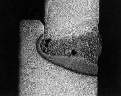
Although inevitable, porosities can easily be brought back to reasonable sizes and densities. They are generally large and round at the bottom and side of the melted well, but small elsewhere (see Figure 9.5). These defects can be minimized by decreasing the welding speed or by oscillating the beam (turbulence). Cold cracking, which can appear a long time after welding, can be avoided by pre-heating and reducing the welding speed.
Figure 9.5. Micrographic section of a laser welded housing (in 3 mm mild steel) onto a clutch (in 16 Mn Cr 5) for an automatic gear box
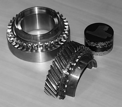
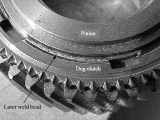
In the automotive industry, the mechanical components concerned by high energy beam welding are often circular, small in size and composite (different steel grades compromises): dog clutch ring for manual gear box pinions (see Figure 9.4), transmissions, forks, etc. In general, laser welds concern complex bead geometries and penetrations lower than 10 mm. The beam’s energy density is about 1 to 10 kW/cm2 (10 times that of an electric arc).
For the CO2 lasers, a significant part of the beam is reflected, at least before the beginning of fusion (95%, then 20%) and it is necessary to improve absorption by use of black paint or phosphatizing. It is also necessary to avoid chamfers for the preparation of butt joined assemblies because they cause, by reflection, a considerable loss of penetrative power.
9.3.2.3. Examples of welded components
Tulip assemblies designate sliding transmission joints acting as a CV joint on the outside of the gear box. As shown in Figure 9.6, they consist of a casing, a spacer and a sleeve carrying the three bearing surfaces on which rest the transmission needle bearings (sliding motion). Often, the casing and sleeve are in XC 42 (for local induction hardening), while the spacer is formed from a low alloyed steel of the type 10 Mn Cr 5.
The casing can be welded onto the spacer and the sleeve onto the spacer by electron beam or laser. For example, at the Le Mans Renault factory, the two welds of the same type of tulip are welded by a 5.5 kW CO2 laser at rates of several thousands per day.
The final local hardening by induction of the bearing surfaces must be stopped 7 mm from the area to be welded to avoid cracking. The welding is carried out by chuck rotation, for the casing initially, then for the sleeve, with a welding overlap of about 10 mm. The time cycle is 1.3 minutes while the depth of the melted zone is about 5 mm on the casing and 2.5 mm on the sleeve. Weld quality is controlled at a rate of two or three destructive micrographic tests per shift.
Another example of laser welding consists of the shielding of tulips in geometries close to that considered above. This shielding is obtained by welding a thin 18/10 stainless steel sheet on the upper part of the sleeve made from XC 42. A 1 mm through-weld, on the opposite side of the laser beam impact, requires only one 800 W source, and obviously no absorption coating, for welding speeds of about 1 cm a second.
Comparative welding tests, with either laser or electron beam, for the same industrial investment of €5.105 and a rate per hour of 400 parts, frankly could not give the advantage to one or other of these techniques. Hourly rates were in both cases around €2 for operational costs, and €8 for maintenance.
The third example of laser welding: that of a pinion in 27 Mn Cr 5 on a gear box input shaft in resulfurized 27 Mn Cr 5 (see Figure 9.7). Taking into account problems of teeth distortions during the carbonitriding treatment at the end of the range, it was necessary to carry out an axial and radial welding of the two parts. In the melted zone, carbon content ranged from 0.23 to 0.39%, and that of sulfur from 0.040 to 0.060%. Weldability depends on the operational configuration. Consequently, the radial welding at 2 cm/sec did not pose any problem, whereas the axial welding, performed with the same halved beam, had to be carried out afterwards (less distortion of pinion teeth) and at half the welding speed to avoid unacceptable cracking.
9.3.3. Friction welding
9.3.3.1. Principle
The process consists of assembling two parts by mutual forging in a solid or semi solid state, the heat for the forging-diffusion bond coming from preliminary friction between the faces to be welded obtained by putting one part into fast rotation and then pressing it against the other. Generated heat increases the temperature of interface without reaching the melting point of the metal [CAZ 96, COL 83].
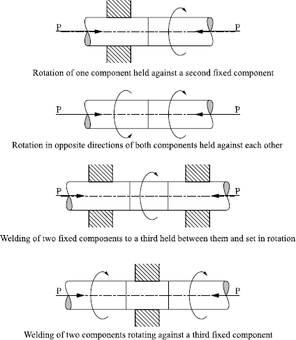
In fact, various friction welding methods exist, as schematized in Figure 9.8. In the elementary lay-out of two components end to end, one being fixed, four phases in the welding operation can be observed:
– setting the moving component into rotation at a constant speed: typically a few hundred revolutions per minute, to reach approximately 2 m/s at the outer edge of the component;
– putting the two components into axial contact: there is heating upon contact, a rise in the resistive torque, but no measurable shortening of the parts;
– maintenance of the axial force until the mating plane reaches the forging temperature. The metal expelled in extreme instances of a semi-liquid state forms a bead, while the parts shorten by plastification of the heated zones. The loss of material begins at the metal solidus: this semi-liquid metal runs out, as a lubricant, towards the outside, under the influence of the compressive force. The duration of this plastic friction is adapted, on the one hand, to the mechanical characteristics of the metals welded and, on the other hand, to the shortening tolerances of the assembly;
– after an abrupt stop of the rotating part, a complementary axial load is applied during a judiciously selected time to carry out the connection through component interdiffusion. The bead increases in volume, the assembly is shortened, and the temperature decreases more or less quickly according to the conduction losses.
Typically, welding of low alloyed steels requires power in the order of 5 CV per cm2 of section at the beginning of friction and half of this during steady rotation. For a bar of medium carbon steel, 20 mm in diameter, the exerted pressures are about 60 MPa for 5 seconds of heating-friction and 100 MPa during the forging-flow stage.
The geometries adapted to this type of welding are generally cylindrical parts of the same diameter at the weld join, tubes, cylindrical faces onto flat surfaces, faces located in a groove, etc.
Metallurgical continuity is obtained by creep interdiffusion and may involve quite different steel grades. The moving component is pressed immediately against the stationary component at the end of the rotation heating stage. The resulting structure depends on the size of the parts and the hardenability of the steels involved, but they are mainly quenched structures due to the high temperatures reached. Almost always, the welded parts need a final heat treatment.
The advantages of the process can be summarized as follows:
– possibility of welding components of different metals and shapes,
– no filler or gas protection,
– reproducible tolerances,
– circumferentially uniform heating, within the solidus of the most fusible metal,
– possibility of automation and on line operation,
– no careful surface preparation (turning + degreasing),
– limited power and low machine maintenance.
The limitations of the process are the following:
– it must be possible for one of the assembly parts must be able to be put in rotation,
– difficulty in heating metals with a low friction coefficient (cast iron, brass, etc.),
– maximum weldable diameters: 150 mm for bars, 250 mm for tubular sections.
It should be noted that many metallic couples can be welded by friction, in particular: steel-aluminum, steel-copper, steel-nickel, etc.
This welding mode is largely used for mechanical components in cars:
– gear box shafts, before machining and carburizing (16 Mn Cr 5) or carbonitriding,
– driveshafts in XC 42 for final hardening by induction,
– bimetallic valves, with a stem made out of martensitic stainless steel and a head from heat resisting austenitic stainless.
9.3.3.2. Some manufacturing examples
Bonding of forged blanks
Some forged blanks may be easier or less expensive to be machined in two parts, with two different steel grades, or through joining parts manufactured by different techniques (hot, warm, cold forging, etc.).
If these parts are axisymmetric, friction welding is required to achieve a robust bond between the parts, in particular when they have different and complex compositions.
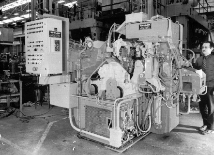
Typically, this process is used to weld gear box input shafts, such as that presented in Figure 9.7 (weight 1.5 kg). In this case, the friction welding machine (of the SCIAKY type presented in Figure 9.9) works at rates of 180 parts per hour with an axial thrust of 250 kN (maximum forging force).
The sub-part whose geometry is more complex (pinion teeth) is hot worked and machined, whereas the other is directly cold forged. The shortening of the welded shaft during the operation is 3 mm, for a component length of 135 mm.
Tulip shaft
Another example of friction welding is the assembly of a transmission halfshaft onto a tulip head at the rate of 12,000 parts per day: the central part of a FWD CV joint should adjoin the driven wheel (see Figure 9.10).
After automatic loading and checking the assembled length, the shaft head is inserted in a chuck and the tubular shaft blocked in a vice. The head is put into rotation at 2,400 rpm, and the friction of the two components is then ensured by a regulation of the axial load. After braking in 0.7 seconds, forging force is maintained until the desired final length is obtained, with constant control of the power consumption. The machine orders the machining of the weld bead only if both of the two preceding parameters are within tolerance; if not, the part is automatically deposited on the conveyer of rejected parts. Periodic visual monitorings of the circumferential regularity of the bead are also carried out. Apart from these controls, the quality of the end product is ensured by respecting the machine’s parameters.
9.3.4. Butt welding by the Joule effect
9.3.4.1. Principle
Flash resistance welding (FRW) or butt welding consists of assembling two parts end to end without a metal filler, using an electric current for heating the interface, then applying a forging force between them [CAZ 93, COL 83, NEG 95].
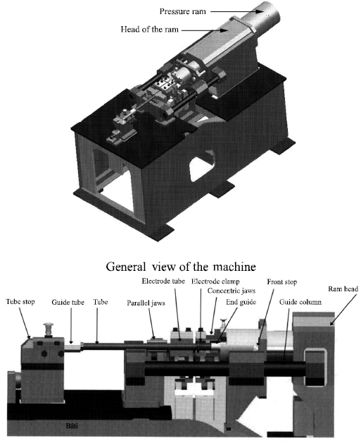
The mechanical part of a butt welding machine (see Figure 9.11) is composed primarily of two chucks enclosing the components to be assembled. The mobile chuck is guided by a carriage driven by an automatically controlled displacement system managing the approach and pressure contact stages.
A step-down transformer is able to provide a current output of several thousand amps at 5 to 15 volts. Once the current is applied, the parts are slowly brought closer so as to maintain an electrical resistance at the interface. The contact asperities are volatilized and as the parts are brought together at a controlled speed, it causes new asperities to melt and be expelled in the form of showers of sparks.
The interface is thus covered in a molten metal film, so that the flash phase plays a triple role:
– heating of the parts, more or less controlled by the flashing duration,
– matching of joint surfaces without too much metal loss over their length,
– limitation of the oxidation risk by interfacial vaporizations.
Welding ends in a rapid high pressure contact with the power off. In addition to the intimate contact of the surfaces to be welded, forging expels the molten metal film containing impurities and oxidized elements from the interface. Speed is as important as pressure, in particular on the thickness of the bead which will have to be machined.
This kind of welding may be preceded by a pre-heating stage so as to reduce the power supply (typically: 0.05 kVA per mm2) and the contact pressure (around 5 hbar).
In FRW processes, a poor matching of the surfaces to be welded during a preliminary stage allows them to be heated to the fusion threshold, while a later pressurized contact makes it possible to laterally expel the interfacial molten metal and oxides, then to create the bond by diffusion in the solid phase. It is not always easy to estimate the flashing duration and to eliminate all trace of oxides or decarburization at the interface.
The majority of alloyed steels, including austenitic stainless types, can thus be welded without post-heating, although this operation is possible for relatively small components heated over small lengths.
In the case of butt welding by the Joule effect without the flash phase, the initial heating is localized by adapting the geometry of the contact surfaces. It is then the speed at which the welding pressures are applied which allows a progressive distribution of the plastic deformations and temperatures compatible with the final geometries and desired joint qualities. A certain number of alternatives to this process can be imagined according to: the speed of pressure application on the parts, the rate of plastification and the evolution of the recrystallization close to the weld, albeit with the main processes occuring in solid phase. The thickness of metal concerned with the plastification-recrystallization and hence the dimensional change in the part can be reduced to a minimum, as well as the size of the martensitic layer and the harmful residual stress zones. It is generally necessary to eliminate the beads by machining, but the moderate brittleness of the martensitic zones in the absence of hydrogen does not necessarily impose complementary treatment if the carbon equivalent content at the interface is reasonable.
9.3.4.2. Example: welding of an end piece on a camshaft
A new generation of camshafts consists of steel cams assembled on a drawn tube, with a steel end envisaged for the drive. Although the tube (26 Mn 5) and the end (forged C25 or turned C35) are made from steel grades that are relatively easy to weld by laser beam, butt welding by the Joule effect may be preferred for the sake of productivity.
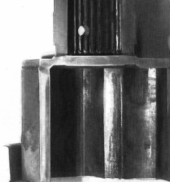
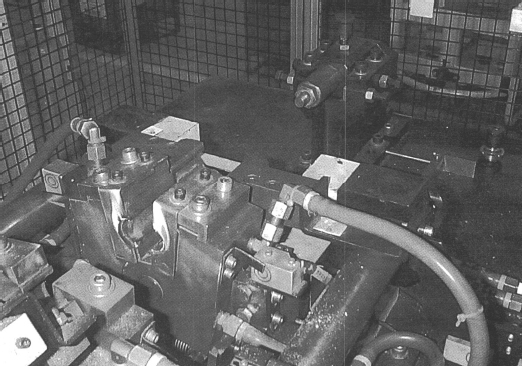
In the machine presented in Figure 9.12, two conducting copper jaws enclose at a distance of a few centimeters from the mating plane, one the flange of the end piece, the other the tube. The latter has a cone shaped machining which, when in contact with the annular face of the tube, localizes the initial electrical resistance of contact. A thrust load of about 1,500 daN is applied constantly to the mobile chuck holding the tube, whereas the jaws holding the end are fixed.
Figure 9.12. Detail of the machine jaws presented in Figure 9.11
The multistage program of electric inputs can be very diverse, with currents of several thousand amps being delivered in multiple periods.
A typical cycle comprises the following phases during 12 seconds:
– putting the two parts in contact under a 1,500 daN load,
– pre-heating for 0.25 seconds at 15,000 A, up to 500°C at the interface,
– a first flash of 0.5 seconds at 28,500 A,
– thermal rehomogenization over 1 second while interfacial creep increases the current passage to the nominal value of the tube,
– a second flash of 1 second at 13,500 A at the end of which the interfacial temperature reaches 1,200°C, the pressure remaining around few Mpa,
– a 2 second diffusion time when the joint at the interface is completed,
– six heating cycles of 0.5 seconds at 11,500 A with a gap between each 0.5 second cycle. This phase is intended to slow down the cooling of the austenitized areas, reduce the martensite extent and improve joint toughness.
At the end of welding, a turning operation is carried out on the bead in order to eliminate the risks of early fatigue crack initiation. The length of the assembled shaft, after cooling, must be precise within a hundredth of a millimeter.
The welding quality is also controlled by the absence of molten metal droplets, which could remain stuck inside the tube and be detached in-service with the risk of obstructing the component’s lubrication.
This type of welding has been proved to offer great flexibility with respect to the various end pieces (depending on engine type) for production line assembly, and good reproducibility with respect to the geometric precision of the assembly and the bending-torsion fatigue strength. Bending strength evaluated by Baldwin tests confirmed the metallurgical health observed in micrographic samples: continuity with ultrasound, absence of oxidation at the initial interface, and a martensitic thickness of several millimeters. The absence of static embrittlement and the good fatigue strength of these areas, even for ends in resulfurized C35 steel, confirm that untempered martensites at 650 HV do not present the cracking risks encountered upon remelting (hydrogen, residual stresses).
9.3.5. Diffusion welding in the solid phase
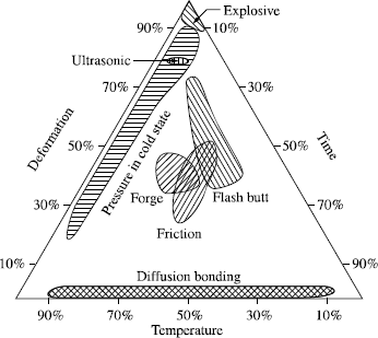
The various assembly techniques in solid phase [COL 83] all call upon the same operational parameters: temperature, pressure, time of action, and we can visualize the areas of variation in these parameters on the same graph (see Figure 9.13), for the most commonly used techniques.
We should particularly note that the graph demonstrates how diffusion welding can be the least deforming and the least disruptive process with respect to the initial structure (volume concerned and extent of damage).
This development is too recent to have reached a level of industrialization comparable with the preceding processes [HOU 91]. However, it is being used more and more in advanced technological industries: nuclear power, armament, aeronautics, electronics, biomedical, etc. This process also has potential benefits with a future for difficult connections like steel-cast iron, high alloyed steels and carburized steels. The more productive version, dynamic diffusion welding, would give this process a place in the manufacturing ranges of traditional industry.
Figure 9.13. Positioning on a temperature-pressure-time action graph for various techniques of solid phase welding
9.3.5.1. Description and characteristics
Such welding requires a careful preparation of the surfaces to be welded in terms of superior interfacial matching, microgeometry, roughness and physico-chemical state (elimination of surface oxides). These are then assembled in a vacuum vessel or in a suitable protective atmosphere, possibly equipped with means of complementary cleaning via ionic sputtering, radiation heating, as well as the clamp making it possible to maintain the compressive pressure (a few tens of MPa) just below the flow limit of the involved metals at the selected temperature. This temperature is always lower than the solidus of the alloys being welded, usually significantly lower to avoid excessive creep affecting the dimensional accuracy of the welded part. The welding time depends on the alloys used. If D is the interdiffusion coefficient and τ duration of interaction under constraint, care is taken that the mean free path of diffusion  exceeds a few micrometers. In fact, the creation of the metallic connection depends not only on interdiffusion and hot recrystallization but also on the resorption of contact defects by a mechanism similar to that of sintering.
Dynamic diffusion welding consists of heating the components to the welding temperature as quickly as possible (induction heating) by modulating the contact pressure at a level just lower than the flow limit of the least resistant material.
Thus, intimate surface contact is very quickly obtained and a strong metallic bond can be established in a few minutes. In this way connections between gray cast-iron and steel have become industrially possible, with an overall strength higher than that of the cast iron [CAL 86].
The macroscopic deformation of the parts can be limited to 2% of the heated length and a subsequent machining can often be avoided, all the more so as the parts assembled under a protective atmosphere are not oxidized.
The localized thermal evolution of the structures during welding does not always demand a complementary heat treatment of the welded joint.
The quality of the welded joint is primarily related to the cleanliness and the intimacy of the surface contacts. A light rubbing together (relative micro-sliding) makes it possible to improve this contact.
9.3.5.2. Potential uses
This type of connection should especially develop in micro-mechanics and for connections of steel-cast iron or high alloyed steels that are difficult to weld by other techniques. So, for example, it is possible to weld carburized or nitrided parts, removing the treatment only from the joint surfaces, either by masking them or by machining. It is also possible to interpose a thin nickel sheet before putting steel surfaces in contact.
Diffusion welding could be used on parts already subjected to thermochemical treatment. The advantage could be a simplification of the ranges and production line flexibility. It was thus employed for carbonitrided tulip drive shafts in 27 Cr Mo 4 [LEP 92], as friction welding does not give good results on these structures.
The welding conditions adopted could be as follows:
– careful mechanical polishing (Rmax = 1 µm) followed by degreasing,
– joining pressure: 300 MPa, cycled during the application time,
– welding in five seconds at around 1,050°C in vacuo.
However, it should be noted that:
– a good interfacial roughness is necessary, whether or not we preserve a carbonitrided layer at the interface;
– the hardness of the carbonitrided layer is lost on the height thermally affected by the inductor;
– it is better to work on grades with less than 0.020% sulfur so as not to affect the interfacial toughness;
– the interfacial properties can be further improved by recrystallization, resulting for example from work hardening due to relative angular oscillations or vibrations of the samples during the temperature rise;
– there would remain microporosities of about 20 nanometers at the interface, stabilized by the diffusion of base metal elements (S, P, N) towards the interface during welding.
Under nearly the same operating conditions, good mechanical joint characteristics can be obtained in diffusion welding for the combinations: SG cast iron/perlitic cast iron and cast iron/steel with interposition of a 10 µm nickel strip.
9.4. Specifications and quality control of the weldings for these components
The various welding modes are obviously the object of operational specifications and quality controls [NOR 83], as is the norm for any mass production of mechanical components.
These specifications, and the corresponding traceability process, are based primarily on former experience, from systematic recordings of the thermal cycles or the thermal source parameters making it possible to control these cycles.
In small-scale machine shops producing low volumes, welds can be individually checked by the various non-destructive testing techniques: penetrant dye testing and magnetoscopy for emerging defects, radiography and ultrasound for internal porosities.
In the high volume automotive and the mechanical engineering industries, the quality control of the production must be both rigorous, flexible and simple, as we will briefly show as an example of safety in the welding operation.
The preliminary study (at the prototype stage) must initially define methods and a range of controls that are easy to implement on the production line; it is one of the keys to successful quality assurance of the manufactured parts. The specifications of the various defects which can affect the weld must be established very accurately with the aim of being both practical and effective. The quality assurance plan, applying and checking these specifications, must be simple and in particular must allow development, without risks, of the frequency of controls, in order to space them out during production. This plan must also make it possible to minimize storage in the body of parts between two controls.
As these two documents have legal authority, it is important to note that all the operations which are mentioned must be verifiable. That justifies the rigorous simplicity which they must have in order to be applied in a realistic way.
9.4.1. Weld quality specifications
9.4.1.1. Contents
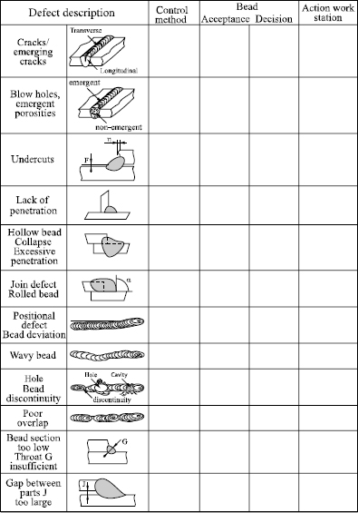
This document must list all the possible weld defects (macro and micro) and give their level of acceptance; it also defines the means to be used to carry out controls.
The acceptable defect levels must be defined precisely and take into account:
– metallurgical risks: appearance of micro-defects such as cracks, blisters, shrinkages, etc.,
– static mechanical behavior of the assembly: traction, shearing, tearing, torsion, etc.,
– dynamic behavior: shock, fatigue.
The metallurgical risks are minimized by the preliminary choice of material (the specifications must mention the acceptable content level of carbon, sulfur, phosphorus, etc.) and, if difficult steel grades cannot be avoided, by the range and the welding parameters (pre-heating, post-heating, reheating in situ, etc.); specifications will detail the means of controlling this operation’s performance, in particular by a printed trace of the machine’s welding parameters.
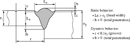
The mechanical strength of the assembly is ensured by the limitation of macro defects and a correct weld geometry: a good general rule is to mention in the specifications that, in all directions of the weld section, the size of the joint must be greater than the thickness of the thinnest part.
The dynamic behavior of the assembly is minimized, with regard to shock, by a metallurgy or welding conditions preventing excessive weld brittleness; in fatigue strength, it is optimized by limiting all the inherent geometric singularities which could lead to crack initiation.
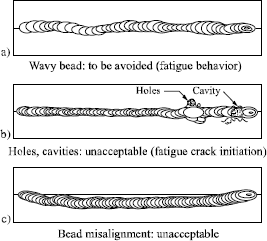
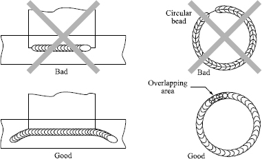
For example, the recommendations of Figures 9.14 to 9.16 show how static and dynamic weld behavior can be better controlled by geometric bead constraints.
Internal micro-defects: their occurrence is mainly linked to the various metallurgical risks already explained.
An example of acceptance for laser or EB welding is shown below.
The control methods for these defects (statistics on a certain number of micrographic sections, ultrasounds, etc.) are difficult to implement in mass production.
It is often agreed that with the precise matching of components, the harmfulness of non-emergent defects remains within acceptable limits. On the other hand, when they are visible on the surface as in the examples attached, their occurrence is no longer tolerable.
A way of reducing and simplifying production control is to tolerate all micro- defects if they cannot be detected in visual monitoring of the bead (with the naked eye or with a reasonable magnification method). This acceptance of internal defects must obviously be justified by preliminary validation testing of the parts.
9.4.1.2. The basic specification schedule
A provisional specification schedule, taking all the above principles into account, is determined for the production of prototype components. This document is important; it enables parts of well-known characteristics to be manufactured serving as reference and facilitating possible future improvements.
In most cases, the recommendations of this provisional schedule make it possible to obtain a welding quality that satisfies the performance requirements of the component during the validation tests.
However, it is possible that, during these tests, loads higher than those envisaged lead to weld failure. A detailed evaluation of the break makes it possible to refine the tolerance levels in order to establish the final specification schedule.
Generally, modifications relate to the joint geometry or a stricter tolerance for defects leading to the start of fatigue cracking.
9.4.1.3. The final specification schedule
This is the document which will be applied when the components are in mass production. Incorporating the modifications resulting from prototype validation evaluations, this document will comprise:
– a list and description of the defects,
– the level of defect acceptance,
– a description of the means to evaluate this level of acceptance.
The method of defect control is not imposed but it must be selected among those mentioned and validated in the specification schedule. The choice of these means and their frequency of application is the subject of the quality assurance plan of the weld.
9.4.2. The quality assurance plan of the weld
This applies and checks the specification methods for each weld of the assembled component.
9.4.2.1. Contents
For each defect indexed on the specification schedule, it will indicate:
– the method of control used to check this defect (precise check of the welding parameters, visual, macrographic, others, etc.);
– the frequency for each one of these controls (100%, every nth part, etc.),
– the decision taken in the event of non-conformity (alarm, rejection of the part or the batch, rectification, etc.); in this last case, a rectification procedure will have to be described and validated,
– actions taken for the filing of control results (logs, graphs, etc.) and to facilitate checks (standard parts, good and bad examples of the components are on hand at the work station, etc.).
An archive table, such as that presented in Figure 9.21, can be used.
A good quality assurance plan takes into account that the selected control methods must be the simplest possible. The checking of the machine’s welding parameters must be encouraged and the consequences of any deviation on the appearance of well-known weld defects. Systems for directly observing the bead after welding (camera, etc.) are to be encouraged, as the following controls are often greatly reduced. Methods of non-destructive testing must be favored in order to minimize the total control costs. With each control, a precise filing of the measured parameters is advised. The storage of batches on standby awaiting control results must, for reasons of product flow, be reduced to the minimum; the follow-up of the parameters, previously quoted, is a good means of ensuring a good quality flow by a system of alert thresholds with immediate corrective action on the welding parameters, without blocking the batch. The frequency of each control must be flexible: close together in development, frequent at the beginning of production, the aim being to space these controls out in the course of production in order to reduce costs. This decision must only be taken on the basis of good record keeping,
This demonstrates the importance of follow-up and filing the control results. A frequency modification procedure will then be written (“after n controls giving satisfactory quality, the frequency control will be…”). As an efficient frequency interval can only be defined by taking the reliability of the material into account, only the users of this material are capable of establishing this.
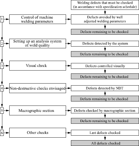
The development of the quality assurance plan: having listed all the defects to be controlled according to the weld specification schedule, the control methods are to be employed in the order given in Figure 9.22. The control plan stops when there are no more defects to detect.
9.4.2.2. An example of a quality assurance plan
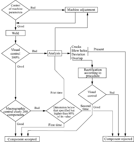
Figure 9.23 gives an example of a quality assurance plan set up for the laser welding of dog teeth onto a gear box pinion.
9.5. Developments and trends
9.5.1. Evolution of the context
We can foresee that increased intervals between disassembly periods for maintenance, the trend towards interchangeable modules and reductions of costs and assembly times will lead to the rise of automated welding. For mass produced mechanical components, we have to be increasingly concerned with:
– installation flexibility: the same machine must be able to weld all the variants of the same or sister component, and will therefore have robotized transfers and sources with a real margin of trajectory training;
– cycle time, which must be adapted to that of machining times;
– delays of tool changes and preventative maintenance which does not inhibit the operational efficiency of the installation;
– on line control requirements.
These process constraints eliminate some small-scale welding or brazing processes employed in mechanized welding for steel construction, as well as some techniques for which suitable industrial machines do not yet exist.
9.5.2. Favored processes
For non-axisymmetric parts unsuited for friction or resistance welding, welding with high density thermal flow seems most promising because the affected structures apply to only a small part of the component, and this in a relatively reproducible way. The example of bimetallic valves, friction welded with a band of some tenths of millimeters of untempered martensite at 650 HV, shows the advantage of drastically reducing the thickness of the remelted layer. The reduced affected zone must, however, be accompanied by a more precise interfacial matching and adequate plastification to allow an intimate contact between the surfaces to be welded. A good compromise between contact precision, localization of the temperatures close to the fusion of the base metal and plastification-recrystallization of the interface are key to automated welding installations for alloyed (or unalloyed) steel components.
Much is expected of compact lasers in terms of production developments (YAG or diode batteries), because they do not imply expensive maintenance.
Let us recall that the heart of a powerful laser diode consists of a row of diodes (0.1 × 0.6 × 10 mm) which emits a very divergent beam (90° × 20°). Typically, such a row emits 30 W for a wavelength around 900 nm. To increase the overall output power, the rows are piled up and the beam divergence corrected by adequate micro-optics directly linked to the rows. It is thus possible to build up very powerful and compact devices, the size of a lighter, supplying some 300 W.
Currently, continuous powers up to 4 kW can deliver power densities of 3.104 W/cm2 at the focal point. The total electrical efficiency is 30%, with lifespans from 10 to 20,000 hours. Work in progress at the Institut fûr Laser Technik in Aix-la-Chapelle are achieving power densities of 106 W/cm2 for powers of a few kW and lifespans higher than 25,000 hours.
The market potential is thus considerable. These thermal sources are coupled with robotized devices carrying out the contact stage and the interface plastification with precision, for a broad range of component geometries and with a controlled dispersion process. Such a transfer machine is often more expensive than the laser source.
The compactness and the reduced investment and maintenance costs also militate in favor of plasma torches with transferred arcs, whose precision of arc positioning is definitely superior to that of blown arc torches.
On the other hand, the extension of diffusion welding technology, beyond micro-mechanics and alloys that are difficult to weld by other means, remains improbable in the near future.
Butt welding by Joule effect will remain limited to the welding of accessories on tubes, but should lead to a better knowledge of exactly what is necessary for the creation of a welded bridge, with or without recrystallization, by taking advantage of transformation plasticity and good ductility in TRIP martensites.
Finally, the developmental perspectives of multipurpose robotized installations could make us reconsider certain metallurgical choices for mechanical components or call into question traditional assemblies.
First example: machine welded front triangular suspension arm out of a sheet steel
The suspension arm connects the wheel pivot to the car body by allowing vertical displacements via a ball joint. It is involved in the rigidity of the suspension with respect to longitudinal forces (acceleration, braking) and lateral forces in bends. To design an economic suspension arm, sheet steel solutions are preferred to hardened forged steels, but it is difficult to take advantage of the higher mechanical strengths of the newest steel grades (high-strength sheets or stainless) because the fatigue failures start systematically at the toe of the weld beads. For the design, it is necessary to move the beads away from the highly stressed zones, which is often difficult for heavily loaded components. An installation linking very localized welding and hardening would be particularly advantageous.
Second example: welding or brazing of pinions on shafts
The possibility of replacing a machined shaft with pinions, which are difficult to harden without excessive distortions, by an assembly of pre-manufactured and hardened pinions which could be welded or brazed on a tubular shaft, would be interesting in terms of weight saving and economy. For helicoidal gear train, the axial and bending loadings in operation justify special attention to weld or braze toe toughness. To avoid softening during brazing, this operation must obviously precede carburizing hardening and occur at a slightly higher temperature.
Finally, in all cases of welding, we are confronted with two alternatives. On the one hand we have a difficult interfacial matching because of shortcomings (for technical or economic reasons) in the geometric precision or preparation of surfaces to be welded. On the other hand, a significant metal and energy supply to the joints resulting in risks of embrittlement because of defects and structures arising in them. Improved precision machining of mechanical components leads us to think that solid phase welding will gain in importance.
9.6. Conclusions
We have pointed out the distinctions, in terms of welding needs, between machine welding of structural steels as studied in previous chapters, and the assembly of mechanical components, often from alloyed steel unsuited to traditional welding with extensive remelted zones. We also evoked the requirements of mass production in terms of cycle time length, automation and quality control.
In this context, welding processes involving a minimum of molten metal are compatible with precision interfacial matching and mechanical finishing. They often seem best placed, from a metallurgical perspective (reproducibility, low levels of shrinkage and porosities, better control of residual stresses, etc.), from the process perspective (automation), and in facilitating quality checks. In these categories of parts, a final heat treatment often reduces the risks of cold cracking related to rather highly alloyed compositions.
Friction welding is the archetypal process for all cylindrical components in relatively high alloyed steels or difficult alloys. It has standardized industrial machines at its disposal capable of handling large runs. The example of friction welded bimetallic valves, with a thin layer of untempered very hard martensite, shows the metallurgical benefit of drastically reducing the thickness of the remolten layer.
More recently, butt welding by the Joule effect is now made possible on automated industrial machines, which can also combine other operations on tubular parts.
Diffusion welding is too recent a development to be suggested for use in standardized industrial machines. However, it may be considered as a last resort for particularly difficult cases of welding where a high degree of accuracy in interfacial matching and cleaning allows enough recrystallization, interdiffusion and microscopic indenting by creep. It seems to be a potentially interesting solution for assembling otherwise unweldable iron alloys.
Between the specific methods that we have just presented and traditional arc welding poorly adapted to high alloyed steels, we find welding processes based on high energy beams: they can limit the “metallurgical damage” of the affected zone to so narrow a layer that it does not have any consequences on the overall behavior. The new lasers working at shorter wavelengths (for good absorption of the radiation) — which are compact, not particularly expensive, easy to set up and inexpensive in maintenance — are commonly seen as the most promising. In this context, electron beam welding should be reserved for thicker parts, long welded lengths or coating of pressure vessels. Moreover, the plasma gun with transferred arc will find its place for mechanical components and welded joints of intermediate size.
9.7. Bibliography
[AWS] American Welding Society, Welding Handbook, 8th edition, Section 1.
[BON 87] BONNET C., “Traitements thermiques associés au soudage des aciers”, Techniques de l’ingénieur, B 7810, 1987.
[BOU 82] BOURGEOIS P., Soudage à l’Arc Tome 3, Procédés avec fil électrode fusible, procédés avec électrode réfractaire, Publication de la Soudure Autogène, Paris, 1989.
[BOU 92] BOURGES P., BERNIOLLES J., “Laser beam welding of high hardness steels: applications to armoured vehicles”, ICALEO’ 92, Laser Institute of America, p. 574-583, 1992.
[BOU 95] BOURGES P., CHEVIET A., “Soudage par faisceau d’électrons d’aciers au chrome-molybdène de forte épaisseur pour application en pétrochimie”, Colloque AFIAP 1995, Paris, 17 October 1995.
[CAL 86] CALVO F.A., “Soldadura por diffusion de materiales ferreas”, Soldadura, 16, 3, p. 125, 1986.
[CAZ 93] CAZES R., “Soudage par résistance”, Techniques de l’ingénieur, B 7720, 1993.
[CAZ 94] CAZES R., “Soudage par faisceaux à haute énergie: faisceau d’électrons et laser”, Techniques de l’ingénieur, B 7740, 1994.
[CAZ 95] CAZES R., “Soudage à l’arc”, Techniques de l’ingénieur, B 7730, 1995.
[CAZ 96] CAZES R., “Soudage par fiction”, Techniques de l’ingénieur, 7745, 1996.
[CAZ 97] CAZES R., “Soudage automatique”, Techniques de l’ingénieur, BM 7750, 1997.
[COL 83] COLLECTIF, Welding, Brazing and Soldering Arc Welding of Low-alloy Steels and Ferrous Metals, Metals Handbook no. 6, ASM, 1983.
[DEB 84] DEBIEZ S., “Détermination des conditions de soudage des aciers faiblement alliés pour prévenir le risque de fissuration à froid”, Soudage et Techniques Connexes, May-June 1984.
[DER 81] DE ROO P., DEVILLERS L., MARANDET B., “Conditions d’amorcage et de propagation d’un défaut localisé dans le métal fondu d’un joint soudé”, Quatrième réunion SFM-SIS, May 1981.
[FAB 83] FABER G., GOOCH T., “Assemblages soudés entre aciers inoxydables et aciers faiblement alliés”, Soudage et Techniques Connexes, March-April 1983.
[FEN 84] FENN J., “Solid phase welding: an old answer to new problems”, Metallic Materials Technologies, vol. 16, no. 7, p. 341, 1984.
[GRA 81] GRANJON H., “Travaux sur le soudage par faisceau d’électrons”, Soudage et Techniques Connexes, January-February 1976, May-June 1981.
[GRA 95] GRANJON H., Bases métallurgiques du soudage, Publications de la Soudure Autogène, Eyrolles, 1995.
[HOU 91] HOURCADE M., “Le soudage-diffusion à l’état solide”, Traitement Thermique — 250-1991, p. 21-29, 1991.
[LEP 92] LE PAGE G., Soudage-diffusion de l’acier 27 Cr Mo 4 et de l’acier 100 Cr 6, PhD Thesis, CNAM, 1992.
[LIE] LIEURADE H.P., “Application de la Mécanique de la Rupture à la fatigue des joints soudés”, Communication IIS, Ljubljana, September 1982.
[MAZ 82] MAZUMDER J., “Laser welding, state of the art review”, Journal of Metals, p. 16-24, July 1982.
[NEG 95] NEGRE J., Le Soudage Electrique par Resistance, Publication de la Soudure Autogène, Paris, 1995.
[NOE 84] NOEL L., “Brasage”, Techniques de l’ingénieur, B 5195, 1984.
[NOR] NORME FRANÇAISE NF E 83-100: “Construction d’ensembles mécanosoudés — Techniques de soudage”, — Partie 1: “Généralités — terminologie — classe de qualité de soudure — étendue des contrôles”, — Partie 4: “Fabrication — Contrôle”.
[VAL 83] VALETTE G., CHEVIET A., “Soudage F.E. de l’acier à 2,25%Cr-1% Mo en forte épaisseur”, 3e CISFFEL, Lyon, 5-9 September 1983.
1 Chapter written by Yves DESALOS and Gérard PRADERE.
