Chapter 10
Welding Steel Structures 1
10.1. Introduction
10.1.1. History
Although electric welding dates from the end of the 19th century, it is a relatively recent technique in steel construction. The shipbuilding, automobile, aeronautical and boiler making industries quickly adopted it, because it presented considerable advantages in weight saving or it solved the problems of water or air tightness. The Titanic was launched in 1911 and the first instance of welded car bodies dates from 1912.
In the construction industry, the first entirely welded metal constructions were a building erected in the USA in 1924, followed by two railway bridges, one spanning 19 m, over Turtle Creek in Pittsburgh in 1928, and the other 27 m over the Sludwia in Lowicz in Poland, in 1929.
In France, the first welded civil engineering projects date from 1936: a 40 m road-bridge at Ourscamp in the Oise, and an 80 m railway bridge of in three spans (two outer spans of 22.5 m and a central span of 35 m) in Paris, Porte de la Chapelle. It should be noted that it was not in the French tradition to construct entirely welded steel buildings.
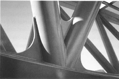
Figure 10.2. Viaduc de l’Arc, TGV Méditerranée — detail of a node Designers: SNCF & GAUDIN Architects — photograph from OTUA
These early large scale welded constructions soon suffered problems, due in particular to brittle fracture phenomenon (see section 10.5.2).
The American Welding Society (AWS) published the first Guide on welding in 1922, then the Code for fusion welding and gas cutting in building construction in 1928 and the Specifications for design, construction, alteration and repair of highway and railway bridges by fusion welding in 1936.
For the French construction industry, the first circular giving Provisional instructions for the execution of electric arc welded steel structures and bridges was published in July 1934. One year later, in the light of the conclusive experimental results, a modified circular removed the term Provisional and increased the acceptable loadings for welded joints, effectively marking the first development of this technique.
10.1.2. Applications
Before dealing with welded steel structures, it is necessary to expand on the fields where they are employed.
It is difficult to give a precise and exhaustive definition, because of the great diversity of constructions.
As examples, we can consider:
– frameworks of agricultural buildings, greenhouses and silos;
– industrial facilities;
– frameworks of buildings used as offices or dwellings;
– road or railway bridge structures, and pedestrian footbridges;
– offshore platforms such as oil rigs;
– electricity pylons, telecommunication pylons, ski lifts and chimneys.
These constructions, of varying complexity, subjected to very different actions (permanent and imposed loads, static or dynamic loads, climatic and thermal forces, possibly seismic phenomena and the effects of fire), as well as to very different requirements as regards personal safety, which further extends this diversity, can also be characterized by inherent construction particularities on-site.
Lastly, it is necessary to take into account the specificity according to use in the same structure of hot rolled long products (mainly I, H and U- shaped beams) tubes, sheets or wide flats (parts of assemblies and welded I-sections or box sections).
This highlights the virtual impossibility of stating general rules that are valid for the structure as a whole; only specific regulations make it possible to deal with various aspects.
It must be noted that the current rules are in booklet 61, title V (Design and calculation of steel bridges and structures) and in booklet 66 (Execution of civil engineering structures in steel) for steel bridges, and in CM 66 (Rules for calculation of steel constructions) and the construction standards series NF P22-XXX for buildings and other works. These documents will undoubtedly be replaced by European standards, respectively Eurocode 3 (steel structures) and 4 (composite steel and concrete structures) for design and calculation, and the standard EN 1090, relating to the execution of the structures, including general rules and specific instructions for buildings, bridges, hollow sections and stainless steels.
10.2. Steels for steel structures
10.2.1. Grades and qualities
The grade of a structural steel in steel construction is primarily defined by the three basic mechanical characteristics: yield strength (the main criterion used to check an element’s strength), tensile strength and elongation strength to fracture. These characteristics refer to uniaxial loads.
A state of multiaxial stresses can, under certain conditions, create a risk of brittle fracture for values significantly lower than the constraint considered acceptable by a traditional calculation of material strength. Also, in addition to stability, it is necessary, according to the construction in question and its technological provisions, and the foreseeable operating conditions (like temperatures down to 30°C in cold stores or for bridges), to ensure safety by controlling this risk.
Within the same grade, and with almost identical basic mechanical characteristics, qualities are defined which offer complementary guarantees against the risks that can be caused by particular conditions of use and service.
The principal criterion for resisting brittleness — i.e. toughness — is sensitivity to the notch effect. This is evaluated starting from the greater or lesser susceptibility of a material to deformation by energy absorption under the effect of a load or a shock. This is determined in experiments by the shock deflection test, known as the Charpy test.
10.2.2. Steels used
In the great majority of structures, non-alloyed steels are used, complying with the standard NF EN 10025-2, whose mechanical characteristics are the following:
– yield strength in a range between 235 and 355 N/mm2,
– tensile strength between 340 and 630 N/mm2,
– elongation to fracture higher than 20% for the current thicknesses,
– KV failure energy of 27 J at +20°C or -20°C.
We also use steels with improved corrosion performance for special applications, according to standard NF EN 10155; their mechanical characteristics are equivalent.
In addition, fine-grained steels are used particularly for civil engineering projects, in accordance with standard NF EN 10025-3, characterized as follows:
– yield strength between 275 and 460 N/mm2,
– tensile strength between 350 and 720 N/mm2,
– elongation between 17 and 24%,
– KV failure energy of 40 J at -20, even 27 J at -50°C.
For specific applications (see section 10.5.1.1), all these steels can be obtained with improved deformation properties perpendicular to the surface of the product, in accordance with standard NF EN 10025-5.
The steels used have a yield strength of 235 N/mm2; they are mainly used in building structures, as girders, bars and flats.
High yield strength steels (HSS) have a limit higher than or equal to 355 N/mm2. They are primarily sheets.
The fine-grain steels obtained by thermomechanical rolling, according to standard NF EN 10025-4, are increasingly used in civil engineering and offshore oil rigs, in the highest grades and in significant thicknesses (greater than 80 mm) due to the following:
– a better aptitude for welding compared to that of non-alloyed steels and for all the processes (except the MAG process with a solid wire) used in steel construction, and without pre-heating. Limiting the presence of hydrogen (see section 10.5.1.2 on the prevention of cold cracking) is achieved by pre-heating (see section 10.5.3.1);
– improved ductility (raised impact failure energy at very low temperatures).
10.3. Steel construction welding processes and techniques
There are a great number of welding processes and each one has an application. The table below recapitulates the various processes usually used and their characteristics, while technical details can be found in Chapter 1 of this book.
10.3.1. Table of the usual processes
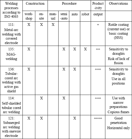
Other welding processes, such as spot, TIG or laser are generally not used, the thicknesses of the elements being too great.
10.3.2. Preliminary operation: tack weld
This operation consists of joining the parts to be assembled by short discontinuous beads before forming the weld itself. Apparently simple, it is actually a delicate operation which requires a great deal of care. Indeed, it must be carried out with the same precautions given to the first pass (filler product, checks, pre-heating or post-weld heat treatment, etc. (see section 10.5.3).
A specific difficulty of tack welds in steel construction is due to the fact that the parts can be very long (a few meters to several tens of meters) or very stiff.
10.3.3. Particular welding techniques
10.3.3.1. Horizontal bench assembly
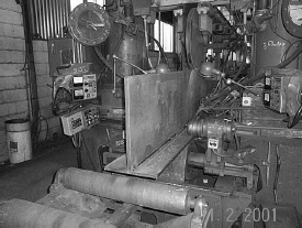
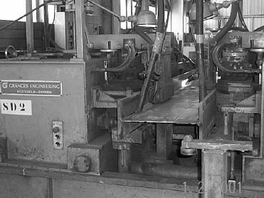
An assembly for the manufacture of I-shaped girders of uniform or slightly variable height, composed of a bench, receiving a flat plate as web and the two vertical flanges placed vertically against its edges, is equipped with two welding heads to create two beads on the same side of the web (process 121). The two other beads are welded after turning over the assembly. This equipment requires a lot of floor space, limits joist dimensions to that of the bench and does not allow the manufacture of curved parts.
Figure 10.3. Construction of an I section on a horizontal bench — photograph from Baudin-Châteauneuf
10.3.3.2. Vertical bench assembly
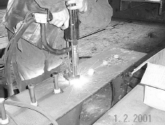
This is a machine for manufacturing a straight or curved (in plan) I section of constant or variable height: a flange is laid down on the bench upstream with the web held vertically by arms; this assembly passes under a gantry equipped with a hydraulic jack and two welding heads to create the web to flange weld (process 121). The T-shaped assembly thus formed is turned over, laid out on the second flange and welded as in the first operation.
10.3.3.3. Stud welding
This technique is used in the workshop or on-site in composite steel-concrete construction for the welding of connectors (diameters from 6 to 22 mm) on steel beams destined to be an integral part of a solid concrete floor. It is carried out using a welding gun in which a stud is pushed into the weld pool, after conducting an electric current, forming an arc.
10.3.3.4. Aluminothermy
This technique is used on-site to join lengths of rails for overhead traveling cranes.
The filler, resulting from the reduction of iron oxide by aluminum, is released in liquid form in a mould of suitable shape to form the joint.
10.3.4. Usual welding positions
According to the joint to be welded, various types of welds are encountered.
In the workshop, fillet and butt welds are most commonly used (see Figure 10.6), the most frequently found positions being:
– flat bead (joint on roughly horizontal surface, with filler metal deposited from above);
– angled horizontal bead (roughly vertical surface placed on a roughly horizontal surface).
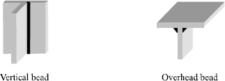
On-site (see Figure 10.7), we will also encounter:
– vertical bead (roughly vertical axis);
– overhead bead (roughly horizontal surface and filler deposited from below).
10.3.5. Edge preparation
As soon as a certain thickness is reached, and according to the process selected, it is necessary to carry out plate edge preparation by creating chamfers to ensure good weld penetration.
With butt welds, two forms of preparation are primarily used depending on the thicknesses to be welded:
– V shaped for low thickness ranges, i.e. from 6 and up to approximately 12 mm,
– double V shaped for mid-range and significant thicknesses, namely from approximately 12 mm to 100 mm and beyond.
The angles of the V or double V shaped preparation vary according to the thickness of the parts and the welding process. These preparations generally include a root face.
The double V preparation can be dissymmetric, to minimize overhead welding, particularly when on-site.
The double bevel preparation (symmetric or not) can be regarded as an alternative to the double V preparation, with the advantage of only needing the preparation of one edge.
For fillet welds, the same type of preparation, V or double V, is found when it is necessary to reconstitute the section or to ensure the full penetration of the weld bead.
These preparations are carried out mainly by grinding for thin parts, or manual or automatic thermal cutting in the other cases.
10.4. Welding distortion
As mentioned above, the thicknesses to be welded are relatively significant. As a result there is considerable heat input which, given the good conductivity of metal, entails the parts being heated.
It is necessary to limit the effects of this heat release, because they produce stresses which lead to distortions needing subsequent correction.
The following distortions are distinguished:
– translation, producing a transverse and longitudinal shrinkage,
– rotational, involving a tightening effect and cambering/folding.
It must be remembered that a lack of ductility in the metal absorbing these stresses can lead to failure due to cracking.
10.4.1. Precautions in execution
To minimize distortion and its effects, several solutions are available and can be combined if necessary:
– choose a welding process with a low linear heat input, MAG for example preferably with tubular cored metal arc welding;
– limit to a minimum compatible with the calculation rules and good practise, the lengths and sections of welds (which also makes good economic sense);
– seek symmetric weld layouts; opposing shrinkage effects avoids distortion;
– perform opposing welds simultaneously to avoid imbalance;
– optimize the order of weld execution, indicated by the term welding sequence, which is governed by the following rules:
- weld with free transverse shrinkage,
- weld symmetrically, with several operators functioning simultaneously, or in alternation with only one operator, observing symmetric (or roughly symmetric) layouts,
- clamp the part in a rigid assembly with opposing preliminary distortion.
10.4.2. Straightening
When it is necessary, in spite of the precautions taken, to correct distortion, this can be carried out by flame straightening or mechanically by hydraulic jacking or with a press.
A local application of heat is often the only means of remedying the defects of a distorted element. It consists of very localized drastic heat application, around 600°C, generating contraction forces during cooling which straighten the element. This operation requires knowledge of the temperature limits when heating which depend on the grades and thicknesses of steel, also bearing in mind that HYS steels require greater precautions when using this technique.
10.5. Defects and their prevention
We recall the usual welding defects such as porosities, cracks, cavities, inclusions, lack of fusion and penetration or defects in shape only as a reminder of a subject dealt with extensively elsewhere in this work.
We will, however, draw attention to the high porosity risk associated with prepainted steels frequently used in steel construction. Its use requires great care, in particular for fillet welds of susceptible assemblies, where paint must be removed beforehand.
We mention primarily metallurgical defects in steel construction and indicate the precautions required to prevent these risks.
10.5.1. Cracks
Two types can be distinguished: cracks due to lamellar tearing and cold cracking.
10.5.1.1. Cracks due to lamellar tearing
Such cracks occur parallel to the skin of a rolled product, at the part of the weld putting strain on the material in the direction of thickness.
The prevention of this risk is mainly achieved by:
– designing joints to facilitate with free shrinkage, while avoiding stresses perpendicular to the skin of products;
– choosing a filler material with a yield strength close to the base metal and operating conditions likely to decrease the stresses perpendicular to the skin;
– Using plates with a guaranteed improvement in deformation properties perpendicular to the surface knowing that the reduction in thickness does not involve a corresponding reduction of the risk.
10.5.1.2. Cold cracking
These are generally located parallel to the fusion line and take various forms according to their position: at the root, at the connection or connection between passes, under the bead. Primarily, there are three causes for this:
– significant compressive and shrinkage stresses at the weld site; the design of the assembly and the choice of the welding sequence generally make it possible to minimize them;
– tempering the metal in the vicinity of the fusion line; limiting the cooling speed in the HAZ is one of the important parameters to decrease this risk;
– presence of hydrogen in the bead; clean and dry parts, baked filler products, electrodes with very low hydrogen and an atmosphere without excessive moisture all serve to reduce the risk.
10.5.2. Fracture
10.5.2.1. Brittle fracture
Brittle fracturing occurs without plastic deformation, unlike ductile fracturing, and develops slowly after a significant preliminary plastic deformation.
The sensitivity of a joint to this phenomenon depends on:
– steel used: yield strength and intrinsic toughness;
– thickness of the components;
– load application speed and levels and nature of stresses;
– lowest service temperature.
In addition to these considerations, risk limitation involves:
– a limitation of work hardening the edges, because this involves a reduction in ductility;
– a welding operation with notch defects such as undercuts;
– low energy welding;
– if necessary, a reduction of the residual stresses with an adapted mechanical treatment of the weld such as hammering.
10.5.2.2. Fatigue fracture
This occurs when a joint subjected to in-service stresses, with cyclic loadings, suddenly cracks and breaks, with very reduced elongation or distortion of the part.
Fatigue behavior depends primarily on the care taken over the weld shape and finishing treatment. This phenomenon is covered in Chapter 6.
10.5.3. Other thermal and mechanical precautions
Thermal precautions make it possible to limit certain risks generated by the specific heating at the time of welding operations.
10.5.3.1. Low pre-heating
This consists of maintaining the temperature of the component between 40 and 80°C during welding, in order to limit the risk of brittle fracture.
10.5.3.2. Pre-heating
This helps to limit the cooling speed by heating the component to between 100 and 200°C, in order to reduce the risks of hardening under the bead and cold cracking in steels sensitive to hardening. It can contribute to a decrease in the level of residual stresses and prevents shrinkage fractures.
10.5.3.3. Post-heating
Post-heating must take place immediately after welding, without the component cooling. This reinforces the effects of preheating with an identical temperature maintained long enough to obtain the equalization of the temperature of the various parts.
Holding the temperature steady also allows the evacuation of hydrogen and aids its diffusion in the mass, which reduces the risk of cold cracking.
10.5.3.4. Heat treatment
This technique is very little used in steel construction because of the dimensions of the components. However, stress relief treatments are commonly carried out on prefabricated tubular nodes in offshore rig structures.
Lastly, post-weld mechanical treatments such as hammering or shot-blasting are sometimes used to improve fatigue strength of welded joints.
10.6. Specificities of non-destructive testing of steel structures
The principal methods of non-destructive weld testing, that is, visual examination, penetrant testing, magnetic particle testing, radiography, gammagraphy or ultrasonic testing, are obviously applicable to steel construction. However, it must be noted that X-ray inspection is unsuited to the examination of fillet welds, and that with ultrasonic tests an uncontrolled zone might remain at the root, understanding that these welds are characteristic in basic metal structures.
10.7. Developmental perspectives
The use of welding in steel construction has developed rapidly and looks to have a promising future because of its many specific qualities. The most important are:
– good structural reliability because welding is carried out using both welding procedure specifications (WPS) and welding procedure qualification records (WPQR);
– simplification of joints, which are otherwise very sensitive to atmospheric corrosion;
– facilitating the continuity of structural elements by using abutment or rigid connections;
– assembly of closed sections;
– optimization of sections, due to simpler joints, and thus economizing significantly on materials;
– possibility of making complicated shapes economically.
1 Chapter written by Jean-Pierre PESCATORE and Jean-Henri BORGEOT.

