Chapter 11
Welding Heavy Components in the Nuclear Industry 1
11.1. General presentation of a PWR pressure vessel
The actual nuclear part of pressurized water reactors (PWR), or nuclear pressure vessels, consists of all the systems involved in generating steam, which is then delivered to the turbines and electric generators.
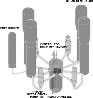
The large components of this boiler are as follows (see also Figure 11.1):
– the reactor vessel where energy derived from nuclear fuel is transmitted to the coolant, known as the primary loop, with water under high pressure (154 bars) and where temperature can reach 350°C. This vessel is a cylinder approximately 12 m in height, 5 m in diameter and 250 mm in thickness, closed by two hemispherical domes. On the vessel a certain number of welded taps of differing dimensions are connected, some of which are the nozzles linking up with the main primary pipes;
– the steam generators where the energy of the primary circuit fluid is converted, through heat exchanger tubes, into steam intended to feed the turbines. The steam generators are approximately 20 m high and have a diameter ranging between 3.5 and 5 m; their thickness is about 100 mm.
NOTE: the water circulation of the steam generators and the system taking the steam to the turbines takes place in C-Mn steel pipes, A42 and A48 grades, similar to the grades used in conventional power generation plants. These materials are not discussed in this chapter.
A pressurizer allows the primary circuit to reach its operating pressure during start-up phases. It is a component approximately 13 m in height, 2.5 m in diameter and 120 mm in thickness. This component also has various connecting nozzles.
Motor-driven pumps ensure the circulation of fluid in the primary circuit.
Pipes, 900 mm in external diameter and approximately 80 mm in thickness, connect the different components listed above.
11.2. Main materials used for manufacturing
11.2.1. Principle of material choice — construction code
The large pressurized components of a nuclear installation must be designed in order to cope with high pressure, at a temperature as high as 350°C, in contact with the primary circuit fluid. Moreover, the reactor vessel is subjected to neutron radiation.
In addition to the safety aspect, the difficulty and the cost of possible repair or replacement operations, associated with an envisaged working life of 40 years, mean that ageing must be taken into account right from the design stage, both for the base materials and for the welds used to assemble the various elements.
Very precise legal requirements appeared in France in the ministerial decree of 26 February 1974 regarding “application of the regulations concerning nuclear PWRs”. This decree puts a legal obligation on the manufacturer to constitute a material file for all the parts subjected to pressure in the principal primary circuit, including the welds of these parts.
Technical and statutory constraints are at the origin of material selection criteria and assembly modes. These choices result from a permanent and ongoing optimization of steel alloys and perfectly controlled processes. The regulations appear in the code of design and construction code (RCC-M) jointly elaborated by EDF and Framatome within the framework of the AFCEN (the French association for construction regulations relating to PWRs).
11.2.2. Low alloyed steels for pressure vessels
The first vessels with pressurized water reactors, brought into service in 1960s USA, were manufactured from 175 mm thick plates in carbon-manganese steel. However, as soon as it was a question of manufacturing high output reactors (initially 300 MWe and now up to 1,450 MWe), the C-Mn steels could no longer guarantee adequate toughness for the pressure vessel thicknesses under consideration. Successive developments have led to manganese-molybdenum steel plates or forgings (ASME SA 302 B), then to Mn-Ni-Mo steel (ASME SA 533 grade B cl 1 plates or SA 508 cl 3) forgings. This last grade has been used for all French PWRs with the additional requirements detailed below. It is designated 16 MND 5 in the RCC-M and is covered by referenced technical specifications.
16 MND 5 is a manganese-nickel-molybdenum low alloy steel, with a bainitic structure, hardened and tempered. It represents an excellent compromise between relatively high mechanical characteristics, making it possible to limit the thickness of the pressure vessels, and a good toughness. Compared to the ASME code requirements, the materials used in France are characterized by a more limited carbon, sulfur, phosphorus and copper content. The lower carbon content makes it possible to improve weldability. Toughness is improved by the reduction of carbon, sulfur and phosphorus. For core shells exposed to radiation, additional requirements relate to the content of copper and phosphorus, the chemicals responsible for hardening and embrittlement by neutron radiation.
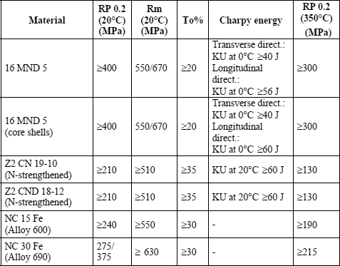
The specified characteristics of 16 MND 5 steel are presented in Tables 11.1 and 11.2.
16 MND 5 steel is used for all the reactor vessel parts (shells, flanges, domes, nozzles). A very close steel grade is used for the pressurizer plates, and the steam generator plates, forged head and tubesheet.
11.2.3. Austenitic stainless steel circuits
Because of their general corrosion resistance and their simplicity, austenitic stainless steels have been used from the outset in solid part manufacturing (pipes, pump and tap casings, reactor vessel internals), or to coat low alloyed steels of large components in the areas in contact with the cooling fluid. The major advantage is to reduce corrosion products liable to be activated when they pass into the reactor core. The first American designers chose grades of the type AISI 304 (18% Cr – 10% Ni) and AISI 316 (17% Cr – 12% Ni – 2.5% Mo) and derived cast grades (CF8 and CF8M).
In France, from the beginning of the nuclear program, low carbon austenitic grades were selected, in spite of the problems encountered when obtaining such grades at that time. The intention was to reduce, even to remove, the risk of sensitivity to intergranular corrosion caused by the dechromization of the grain boundaries during welding operations or stress relief. For this reason, in collaboration with EDF, Framatome and Creusot-Loire, two specific grades were created (see Tables 11.1 and 11.2):
– the nitrogen-hardened Z2 CN 19/10 grade, with a very low carbon content, but with mechanical properties equivalent to those of the high carbon grade of the AISI 304 type,
– the nitrogen-hardened Z2 CND 18/10 grade, equivalent to AISI 316.
The austeno-ferritic alternatives of these two austenitic grades, intended for castings (pump casings, primary circuit pipe elbows), are Z4 CN 20-09 M (CF8) and Z4 CND 19-10 M (CF8M).
The austenic and austeno-ferritic stainless steels undergo an annealing treatment at high temperature followed by water quenching (hyper-hardening). This confers a homogenous structure upon them, free from carbides and optimal from the perspective of corrosion resistance. The ductility and sudden breaking strengths of these materials are extremely high. Their tensile characteristics are weak (see Table 11.2), which excludes their use for large pressurized components.
These steels are easily weldable with appropriate austeno-ferritic fillers. Contrary to the case of low alloy steels, they require neither pre-heating, post-heating, or relief treatment and as such constitute ideal materials for on-site assembly. For this reason, low alloyed large steel components have safety connectors made from austenitic stainless steel in order to facilitate their connection with on-site pipework.
Forged or rolled stainless steels are used for primary pipework. Molded austeno-ferritic steels are used for pump casings and certain primary circuit pipe components.
11.2.4. Nickel alloy parts
Nickel based alloys of nickel-chromium-iron type have an excellent corrosion resistance including chloride mediums, contrary to stainless steels. If we add their good heat transfer characteristics, the reasons for choosing these materials in steam generator piping are easily understood.
Alloy 600 (NC 15 Fe) is chosen, an alloy with 75% Ni, 15% Cr and 8% Fe, whose corrosion behavior was regarded as exemplary. Ni-Cr-Fe alloys have another interesting property: a dilation coefficient relatively close to that of low alloyed steels. For this reason, alloy 600 was also used for cross-sections, pipe take-offs and the internal supports of the large pressure vessel components. Moreover, the procedures and filler products (alloy 82 and 182) for the welding of alloy 600 were well established.
Alloy 600’s sensitivity to stress corrosion in water from the primary loop has gradually come to light. From the end of the 1970s, French and international work programs were devoted to the characterization of a replacement alloy, alloy 690 (NC 30 Fe), comprising approximately 30% Cr, as well as corresponding welding products (alloys 52 and 152). About 15 years of tests in many laboratories, including those of the CEA (the French atomic energy commission), EDF and Framatome, made it possible to confirm the corrosion resistance of this material in the primary loop water medium. This material is now systematically used in France to replace alloy 600 on a purely preventative basis in the majority of its applications. The respective chemical compositions of these two alloys are presented in Table 11.1.
As for austenitic stainless steels, the heat treatment consists of an annealing at high temperature followed by a hardening. Hardening is not quite as fast to avoid a certain sensitizing of the grain boundaries. To produce an unsensitized material, a complementary treatment is carried out at 715°C, for a sufficient time to recharge in chrome the grain boundaries.
Ductility and the breaking strength of Ni-Cr-Fe alloys are extremely high. Their tensile characteristics when hot are appreciably higher than those of austenitic stainless steels (see Table 11.2).
These materials are not as easy to weld as austenitic stainless steels. They present a marked tendency to hot micro-cracking, either during the solidification of the metal added by welding, or in the HAZ. A very careful optimization of the chemical composition is necessary to combat this tendency, with particular attention given to low impurity contents and high Nb/Si ratios.
Ni-based alloys are used for steam generator tubes and partition plates, along with the CRDMs and instrumentation tubes and the core support pads.
11.3. Welding of large low alloy steel components
Large components are made up of forgings or rolled components assembled by welding.
The major parts of these components are:
– for the pressure vessel: the upper dome, closure head flange, vessel flange, nozzle shell, both core shells, transition ring and lower dome;
– for the steam generator: the upper head, two shells of the upper part, feedwater nozzle, manways, conical shell, three shells of the lower part, tubesheet, head with nozzles and manways;
– for the pressurizer: the upper head with its nozzles, three shells, lower had with its nozzle.
11.3.1. Properties aimed for
The requirements regarding mechanical properties of the large component welds, as specified in RCC-M code, are identical to those of the base materials, set out in Table 11.2. With regard to chemical requirements, particular values depend on weldability constraints, for example resistance to hot cracking for austenitic alloys such as stainless steels or nickel alloys. These chemical compositions are indicated in Table 11.3.
11.3.2. Procedural description
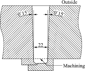
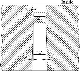
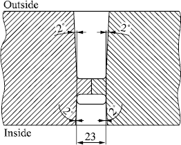
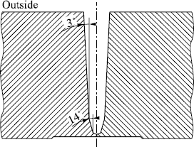
Welding of the parts that make up large components (pressure vessel, steam generator, pressurizer) is carried out by an automatic electric welding process under a powder flux with a wire electrode in a narrow chamfer (approximately 22 mm wide) with the deposit of two beads per layer.
Two types of welds are used:
– welding on only one side (external side) with overthickness located towards the inside to eliminate root passes (see Figure 11.2),
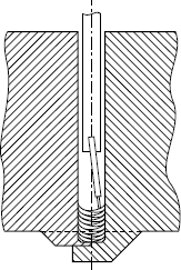
– welding on both sides (outside and inside) with elimination of root passes by grinding or machining (see Figures 11.3 and 11.4).
Throughout the welding operation, the welding speed is controlled and a guidance system also ensures correct positioning of the head with regard to the weld pool as well as to the chamfered edges.
This highly productive process, while giving excellent mechanical characteristics, particularly in terms of impact strength, makes it possible to achieve a weld of zero defects thanks to its complete automation and by the regular and symmetrical laying down of passes in the chamfer (see Figure 11.5).
Figure 11.6 demonstrates the regular build up of passes which is made possible by the narrow chamfer wire/flux process.
To contribute to guaranteeing very high weld quality, the construction codes (RCC-M, ASME, etc.) oblige compliance with a precise process which involves:
– checking the chemical composition and the mechanical characteristics of the filler products,
– a legitimate welding procedure,
– a qualified welder or operator,
– production of test weld samples,
– non-destructive testing of the welded joints.
Welding procedures are legitimized before implementation. The validity of the procedure depends on:
– grade of the base metal,
– shape and dimension of the base metal,
– welding process,
– filler products,
– type of welded joint,
– welding position,
– welding parameters,
– heat treatments.
The legitimacy is checked and test samples are taken to verify the chemical composition under macrographic and micrographic examinations.
Each welding is carried out according to a procedure described on a welding data card and by welders who have passed the qualification tests.
All the welds are monitored by radiography and/or ultrasound. Any defective welds are repaired and undergo a second control procedure.
Pilot coupons are produced with the same filler products and the same welders as the joints that they represent and then monitored by radiography and/or ultrasound. From these coupons, test samples are taken for macrographic examinations, verifying the chemical composition and mechanical characteristics.
Precautions are taken to avoid cold cracking:
– powder fluxes are subject to baking at controlled temperatures,
– the welding of low alloy Mn-Ni-Mo steel requires pre-heating to a temperature higher than 150°C and a post-heating thermal treatment.
After welding, the welded joints undergo a stress relieving heat treatment at 610°C, which aims to decrease the level of residual stresses.
11.3.3. Welding with coated electrodes
Electric arc welding with fusible coated electrodes is used for local repairs like the assemblies of small pipes or accessories.
The process, the criteria concerning the mechanical characteristics, controls and more generally the requisite joint quality are the same as those for joints welded by the automated wire/flux process.
11.4. Cladding
The technology of reactor pressure vessels (RPVs) with pressurized water attaches a particular importance to the prevention of the corrosion phenomena. This importance is due initially to the fact that the whole of the primary circuit contains water at high temperature in which boric acid and lithine are put in solution. The materials which constitute the internal surfaces of the primary loop’s equipment are placed in a medium which allows their generalized corrosion. Limiting generalized corrosion requires the use of stainless steels or alloys with high nickel content for surfaces in contact with the primary fluid. Bare low alloy steels have, in fact, a generalized corrosion rate in the primary loop medium which remains low (about 30 microns per year), but is considered unacceptable because of the products it releases.
The concerns about generalized corrosion of steels are thus not due to the slow destruction of metal surfaces but to the formation of chemical compositions which, put in solution or suspension in the primary fluid, would be likely to stop the vessel from being used, because of the following phenomena:
– reduction in the heat transfer coefficients due to the corrosive products deposited on the heat-exchanger surfaces (SG tubes, fuel sleeves),
– increase in pressure losses,
– increase in the activity induced in the whole of the primary loop by activation in the reactor core of corrosive products in solution or suspension in the medium of the primary circuit,
– acceleration of localized corrosion,
– deterioration of valve parts and fittings,
– malfunction of instrumentation devices,
– disruption of monitoring checks due to the presence of corrosive products on surfaces.
Obtaining a low emission level of corrosive products was thus the top priority in the selection of materials used for surfaces in contact with the primary loop fluid.
Consequently, the search for materials with a low emission level quite naturally led towards materials with a very low generalized corrosion rate in the primary loop fluid, hence the choice of stainless steels and nickel based alloys.
For large-sized vessels — RPVs, steam generators, pressurizers — taking into account the thicknesses in question prevents the use of intrinsically corrosion resistant materials, and so low alloyed steel is the material of choice. To obtain a low emission level, surfaces are lined with stainless steel (308 L or Z 2 CN 20-10) or with nickel-based alloys by the arc welding process. In the case of the material used for the tube banks of steam generators, it was necessary to employ a nickel based alloy with a very good generalized corrosion resistance in both the primary and secondary circuit medium and also possessing an excellent localized corrosion resistance in these mediums. This is why stainless steel is replaced by a nickel-chromium-iron alloy on the surface of the tube plate. The welding of the nickel-chromium-iron alloy tubes can thus be carried out under better conditions, between compatible materials, and avoiding the risk of hot cracking.
11.4.1. Cladding method
Cladding is applied using the automatic welding process with powder flux and strip or electric arc welding with fusible coated electrodes.
Two major procedures are used for automatic strip welding:
– welding under solid flux,
– welding under an electroconducting flux.
The strip is 30 to 60 mm wide for welding with a solid flux and from 50 to 75 mm wide for welding with an electroconducting flux. The strip width can be adapted for example to match a conical component (connecting parts of different thicknesses).
The electroconducting flux process is used for cylindrical shells. In heads, the electroconducting flux process cannot be used in connection areas, and it is replaced by the solid flux process.
Stainless steel cladding comprises two or three layers depending on the expected thickness, the first layer carried out using a strip with 24% Cr and 12% Ni results in a deposit, taking into account dilution, with a chemical composition in the order of 20% Cr and 10% Ni. The second layer and possibly the subsequent layers are produced with a strip of the 20% Cr and 10% Ni type.
Special precautions are taken concerning thermal welding conditions, the welding parameters and the relative bead positions to avoid cold cracking and cracking on reheating.
Coatings using electrodes are used in the case of repair and on small surface areas, or to connect coatings carried out by automatic welding. The use of a 24% Cr and 12% Ni electrode is required for the deposit of the first layer, whereas for the following layers a 20% Cr and 10% Ni electrode is used.
As for automatic strip/flux welding, precautions are taken concerning thermal welding conditions and the welding parameters required to avoid cold cracking.
11.4.2. Cladding inspection
Ni-Cr-Fe alloy and stainless steel coatings are inspected by ultrasonic testing to check the absence of defects in the interface. Chemical analyses are carried out on the stainless steel cladding surface to check that the carbon percentage is lower than 0.035%.
11.5. Welding of stainless steel circuits
The circuits made from austenitic stainless steel are used to connect the various pressure components described above. The main primary pipes have dimensions up to 900 mm in diameter and 80 mm in thickness; taps and pipes with a smaller diameter are connected to these primary pipes; they are called auxiliary pipes.
Since Chapter 12 is dedicated to the welding of stainless steels, it is sufficient here to mention the peculiarities of nuclear installations. A certain number of prefabricated welds are carried out in the workshop transporting the sections to the site: the traditional electric arc processes with fusible coated electrodes or automatic electric welding with powder flux and wire electrode (wire/flux) are most often used. On-site, for welding small pipes or taps, coated electrode processes or manual TIG welding are used (with the electric arc in inert atmosphere and tungsten electrodes).
For on-site assembly of the largest pipes, the process initially used was manual welding with coated electrodes, but the demand for quality and productivity has led to a progressive evolution. Moreover, these manual processes cannot be easily employed when operating in irradiated zones while repairing or replacing of components. For these reasons, automatic welding processes, such orbital TIG welding in various positions, have been developed, initially with traditional chamfers, similar to those used in the manual process with coated electrodes (see Figure 11.7), then with a narrow chamfer (see Figure 11.8).
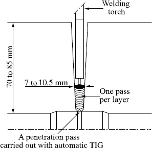
The principle of narrow chamfer orbital TIG welding is presented in Figure 11.9. It is a single pass layered welding process, with string passes, using a 1 mm diameter cold wire of 316L grade, in a narrow gap from 7 to 10.5 mm in width. This process makes it possible to weld in various positions, including on a vertical axis (2GT), horizontal axis (5GT) and tilted at 45° (6GT).
The advantage of the narrow chamfer orbital TIG process lies primarily in the simplification of operation, and results in improved productivity. The gains in time and filler metal is 1 to 4 when the narrow chamfer process is compared with the other wide chamfer processes, such as can be noted in Table 11.4. It is clear that these gains are the direct consequences of the narrowness of the chamfer.
This process also improves reliability and metallurgical quality. Thanks to the simplicity of the process and the guarantee of stable parameters from the root to the final filling, a homogenous welding is obtained, made up of completely identical passes, as can be seen in Figure 11.10. Moreover, this type of welding shows excellent mechanical characteristics.
11.6. Dissimilar metal interfaces
Heavy components (RPV, steam generator, pressurizer) are made of low alloyed steel clad entirely with stainless steel, whereas the primary pipes are actually made from stainless steel. This type of design requires welding of the low alloy steel nozzles to austenitic or austeno-ferritic stainless steel pipes. Such an assembly necessarily requires on-site welding operations.
In order to carry out this welding operation when using a cold austeno-ferritic material, a stainless steel buttering is carried out in the factory at the end of the pipes, onto which is almost always welded a stainless steel safety end fitting.
Because of this the connection between the pipe and piping comprises the following materials (see Figure 11.11):
– pipe base metal in low alloy steel,
– interior lining of the pipe in stainless steel,
– buttering of the pipe end in Ni-Cr-Fe alloy or stainless steel,
– junction weld with the safety end fitting in stainless steel or Ni-Cr-Fe alloy,
– buttering of the safety end piece with Ni-Cr-Fe alloy. This buttering is not necessary if the weld is carried out in stainless steel,
– base metal of the stainless steel end fitting,
– welding of junction between the end fitting and stainless steel piping,
– base metal of stainless steel piping.
The buttering of the stainless steel nozzle end makes up the dissimilar metal interface. When the weld material is stainless steel, welding is carried out either by hot wire TIG process or manually with coated electrodes, the first layer being in 24% Cr and 12% Ni and the subsequent layers in 20% Cr and 10% Ni. When the welding is in Ni-Cr-Fe alloy, it is carried out by the hot wire TIG process. All the layers of added metal which can affect the base metal thermally are carried out with pre-heating and post-heating. This precaution offers the maximum guarantee against the risk of cold cracking.
These dissimilar metal interfaces mandatorily undergo a stress relieving heat treatment. They are inspected by radiographic and ultrasonic testing.
A narrow gap TIG process with a Ni-Cr-Fe filler — without buttering the pipe and end fitting — should replace the existing process in the future.
11.7. Welding of steam generator pipes
The tubes of the tube bundle through which the primary loop fluid flows are welded to the tubesheet coated beforehand with a Ni-Cr-Fe alloy.
The tubes, whose diameter is close to 20 mm with a thickness around 1 mm composed of a Ni-Cr-Fe alloy with 30% Cr, are welded by an automatic TIG process without filler in two consecutive turns and using a pulsed welding current. This current contributes to the maintenance of the weld pool during the operation and makes it possible to obtain a good compactness and sound weld surface (absence of oxide layers).
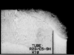
Test coupons are carried out regularly, with the welds being examined by macrography and micrography (see Figure 11.12). The criteria of acceptance particularly take the throat value and size of microporosity pits into account.
These welds undergo many non-destructive tests, with the following being particularly prominent: visual checks, dimensional, penetrant dye, radiography and water tightness (helium test).
Before welding, the tubes are brought together by mechanical expansion over a short length (<25 mm), the aim of which is to ensure correct location of the tube for the welding operation. A correctly carried out positioning prevents a decohesion forming at root level that does not conform to the criteria in the construction code. Moreover, this positioning should not be too forceful in order to avoid a failure in water tightness in the helium test carried out after the welding of the tubes. Figure 11.13 gives a representation of the assembly immediately after welding.
After welding and non-destructive tests, full depth expansion of the tube in the plate guarantees the following functions:
– protection of the tube weld with respect to the forces exerted on the tube bundle in operation,
– mechanical resistance,
– closing the tube/hole gap on the secondary side limits the penetration of the secondary fluid into the tube/hole interstice.
Expansion consists of increasing the tube diameter in the hole to obtain a residual interface pressure between the tube and hole surfaces, after spring back.
The expansion can be obtained:
– either by a hydraulic process of fluid pressurization in the tube; a very high pressure is necessary (≥2,000 bars),
– or by expansion, which is a mechanical process with revolving rollers.
11.8. Conclusions
Because of the high stakes both in terms of safety and industry, the manufacture of components for PWR nuclear plants uses tested and proven materials and assembly processes.
Since the first choices made by designers have proved largely judicious, subsequent developments have been minor with regard to materials: the chemical composition ranges have been narrowed down and the impurity contents decreased; knowledge of their properties has progressed significantly and a substantial database has been established starting from the tests carried out to qualify materials used for the manufacture of 70 nuclear plants during the past 25 years.
With regard to the assembly processes, there have been continuous improvements in efficiency and quality by adopting, whenever possible, well controlled automatic processes.
The final objective of all these improvements remains the demonstration of operational aptitude of the components under all operating conditions and for the lifespan of the reactor.
1 Chapter written by François FAURE and Léon DUNAND-ROUX.
