Chapter 4. Using a Microscope
Equipment and Materials
You’ll need the following items to complete this lab session. (The standard kit for this book, available from www.thehomescientist.com, includes the items listed in the first group.)
Materials from Kit
Goggles
Forceps
Ruler (millimeter scale)
Materials You Provide
Gloves
Lamp or book light
Microscope and illuminator
Scissors
Slide, prepared (bacteria or diatoms)
Specimen: notebook or copy paper
Specimen: snippet from cover of this book
Background
Biology as a modern science would not exist without the microscope, just as modern astronomy would not exist without the telescope. Both perform the same function: making the invisible visible. Without microscopes, biologists would be literally blind to the vast majority of the world around them.
When we took our first high-school biology courses more than 40 years ago, they focused on survey segments—such as examining different types of plants for gross similarities and differences—and dissections of frogs and other unfortunate specimens. We were lucky to get in a few minutes a week using a microscope.
That wasn’t because surveys and dissections were the best way to learn biology. It was a matter of necessity. Microscopes were very expensive, and most school budgets were too small to provide enough of them. Many biology classrooms had only one microscope. Or none. Nowadays, although excellent inexpensive microscopes are available, most schools still come up far short, requiring each microscope be shared by two, three, or even four students. That’s no way to learn biology. Every student needs his or her own microscope.
It’s not that a student will be using the microscope every moment of every day, but that the microscope needs to be available on the spur of the moment. Every time you encounter something new to you, your first thought should be, “I wonder what this looks like under the microscope.” And your first action should be to get it under the microscope to find out.
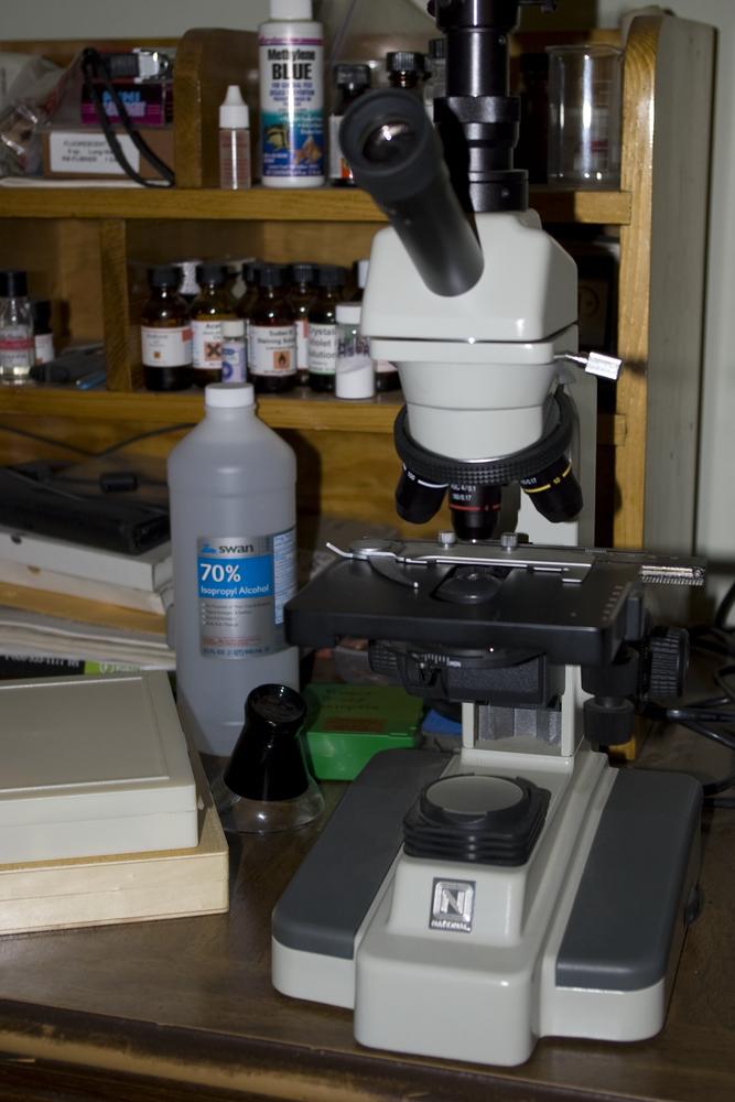
If at all possible, you should dedicate a work area to microscopy, where the microscope and its accessories are safe from lab spills and always ready to use at a moment’s notice. For example, although our main lab is downstairs, Robert’s microscope station, shown in Figure 4-1, is a large desk next to his (even larger) main office desk. (Yes, this is an actual unretouched image of a real working microscope bench. We didn’t clean up or move anything before we shot this image, other than removing the cover from the microscope.) Switching from using the computer to using the microscope takes literally seconds, which means there’s never an excuse not to check something out under the microscope.
Different models of compound microscopes are more similar than different, but some differences do exist from model to model. The two most obvious visible differences you’re likely to encounter are the presence or absence of an inclination joint, which allows the microscope to be tilted, and whether the microscope focuses by moving the stage or the body tube.
Whatever the particular configuration of your microscope, it’s important that you be able to identify each feature and understand how it is used properly. With practice, operating your microscope should become second nature. For example, you shouldn’t have to think about which direction to rotate the focus knob to open or close focus or which direction to turn the mechanical stage control to move a specimen to the right in your field of view.
In addition to learning to use the microscope itself, you also need to learn some basic microscopy techniques, including basic slide making, making whole mounts, smear mounts, and sectional mounts, determining the dimensions of specimens, simple staining, and differential staining. There’s always more to learn, but mastering these fundamentals provides a firm foundation.
The only way to master your microscope and basic microscopy techniques is with practice and more practice. So, let’s get started.
Procedure I-1-1: A Microscope Tour
To begin, place your microscope on a flat, stable surface. Remove the dustcover, and plug in the power cord, if applicable. Refer to the diagram in your microscope manual that identifies the key parts of your microscope and then locate and identify those components on your microscope.
Opening and Closing Focus
To avoid confusion, we use the terms open focus and close focus rather than the more common “focus up” or “focus down” throughout this book. Open focus means to increase the separation between the stage and the objective lens; close focus means to decrease that distance.
The potential for confusion arises because different microscopes use different means of focusing. Some keep the objective lens fixed and raise or lower the stage to focus; others keep the stage fixed and raise or lower the objective lens. With the first type, lowering the stage opens focus; with the second type, lowering the objective lens closes focus.
Controlling and Focusing the Light
Observing from the side of the microscope, use the coarse-focus knob to open focus on your microscope until the stage and objective lenses are as far apart as possible.
Turn on the illuminator and adjust it to maximum brightness.
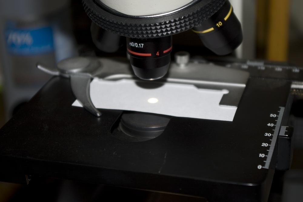
Place a piece of thin paper (such as copy paper) on the stage, positioned to cover the hole in the stage. Secure the paper flat against the stage using the stage clips or mechanical stage. A bright illuminated circle should be visible through the paper, as shown in Figure 4-2.
If your substage condenser is focusable, rack the focus up and down and note the effect on the size and sharpness of the illuminated circle on the paper.
Locate the diaphragm control. If your microscope has an iris diaphragm, this control is probably a lever or knob. Adjust that control to open the diaphragm to maximum. If your microscope has a disk diaphragm, rotate the disk to place the largest opening in position over the substage condenser lens. Close the diaphragm gradually (or rotate each smaller disk opening into position) and note the effect on the size and brightness of the illuminated circle. When you finish, open the diaphragm again to its widest setting.
Use the rheostat (dimmer switch) to decrease the illuminator brightness to minimum and then back up to maximum. Note the range of brightnesses available.
Focusing the Microscope
Observing from the side, rotate the turret (nosepiece) until the low-power (4X) objective is in position. Note that this objective is the shortest of the objectives in the turret. The 10X objective is longer, the 40X objective longer still, and the 100X objective longest of all.
Gently turn the coarse-focus knob to close focus until you reach the focus stop, at which point you can no longer close focus. Note that there is still a significant amount of separation (called working distance) between the bottom of the 4X objective lens and the top of the stage.
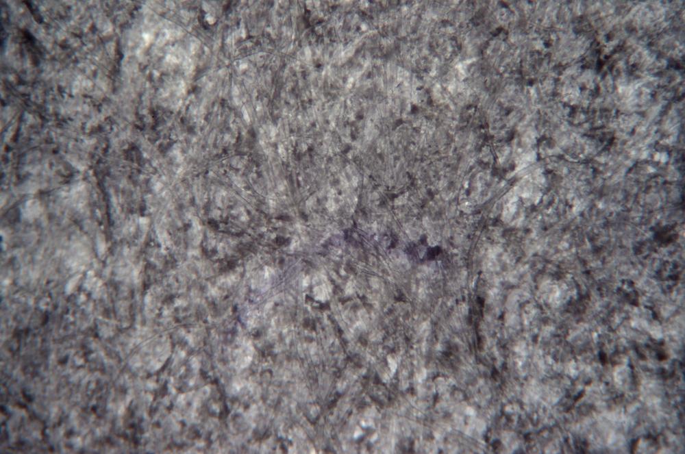
Looking through the eyepiece, use the coarse-focus knob to open focus gradually until the first paper fibers come into reasonably sharp focus. Note that only part of the fiber you’ve focused on is in focus and that many of the fibers are still completely out of focus, as shown in Figure 4-3. This occurs because the specimen you are examining is three-dimensional (has depth). Even at low magnification, the image has very shallow depth of focus, so you can focus sharply on only small portions of it at a time.
Use the fine-focus knob to tweak the focus on the fibers. Note that as one part of the field of view comes into sharp focus, other parts go out of focus. This phenomenon occurs unless the specimen is effectively planar (two-dimensional), with all of it falling within the depth of focus. Because depth of focus decreases with increasing magnification, a specimen that appears planar at 40X may show depth at higher magnifications.
Determining Field of View and Measuring Specimens
The field of view specifies how much of a specimen is visible in the eyepiece. Field of view and magnification are inversely related: the higher the magnification the narrower the field of view, and vice-versa. For example, at 400X the field of view is one tenth as wide as at 40X. For optical microscopes, field of view is usually specified in millimeters for low magnification objectives and in micrometers (μm, or one one-thousandth of a millimeter) for higher magnifications.
Open Wide
A wide field of view makes it much easier to locate objects, which can then be centered in the field and examined at higher magnification. For that reason, the low-magnification objective is sometimes called the scanning objective.
Knowing the true field of view at each magnification allows you to make quick estimates of the actual size of objects in the field. For example, if you know that the true field of view is 400 μm (0.4 mm) wide and the length of a paramecium occupies half that field, you know that paramecium is about 200 μm (0.2 mm) long.
Place a millimeter-scale ruler on the stage, with the edge centered under the low-power objective.
Note
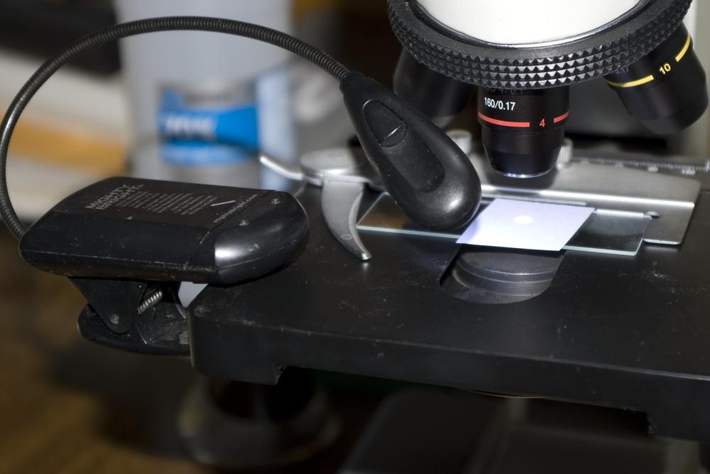
Thick or opaque objects are best viewed by reflected rather than transmitted light. You can use a desk lamp or other light source to illuminate such specimens from above. We use a Mighty Bright book light for this purpose, as shown in Figure 4-4. Its goose neck makes it easy to position the light for best viewing and its dual white LEDs provide plenty of light.
Focus carefully on the edge of the ruler and then position the ruler so that one index line is at the edge of the field of view and the edge of the ruler bisects the field. Count the number of divisions visible in the field to determine the true field of view in millimeters. (At 40X you’ll probably be able to see about five markings, indicating the field of view is about 5 mm.)
Carefully rotate the medium-power objective into place and refocus on the edge of the ruler. At 100X magnification, your true field should be about 2 mm.
Carefully rotate the high-and-dry objective into place and refocus on the edge of the ruler. At 400X, your true field should be about 0.5 mm, with only one index line visible.
Note
Note that the 10X objective barrel is longer than the 4X objective barrel, and the 40X objective barrel is longer still. As you rotate higher-power objectives into position, the decrease in working distance is obvious when viewed from the side.
Note further that you can always safely rotate a higher-power objective into position if the lower-power objective is already focused. The reason you should always start with the lowest-power objective is that the focus stop on the microscope prevents it from coming into contact with the slide, which is not true of the higher-power objectives. If focus is closed too far on a lower-power objective, rotating the next higher-power objective into position may crash it into the coverslip, damaging the slide or (worse) the objective lens itself.
If you have an ocular micrometer, also called a graduated eyepiece reticle, you can use it to determine the size of objects with high accuracy. For example, if your reticle is divided into 100 units and you know that those 100 units cover a 400 μm field of view, each reticle unit represents 4 μm. If a paramecium is 46 units long and 11.5 units wide, you can calculate its actual size as 184 x 46 μm.
The obvious problem is that the actual distance spanned by each reticle unit varies with the magnification you’re using. Using a millimeter ruler gave us a crude idea of field width, but to calibrate an eyepiece reticle accurately, we need a ruler with much finer graduations. We need something that provides a regular, accurately spaced array of microscopic marks at a known separation. You’re holding the solution right now.
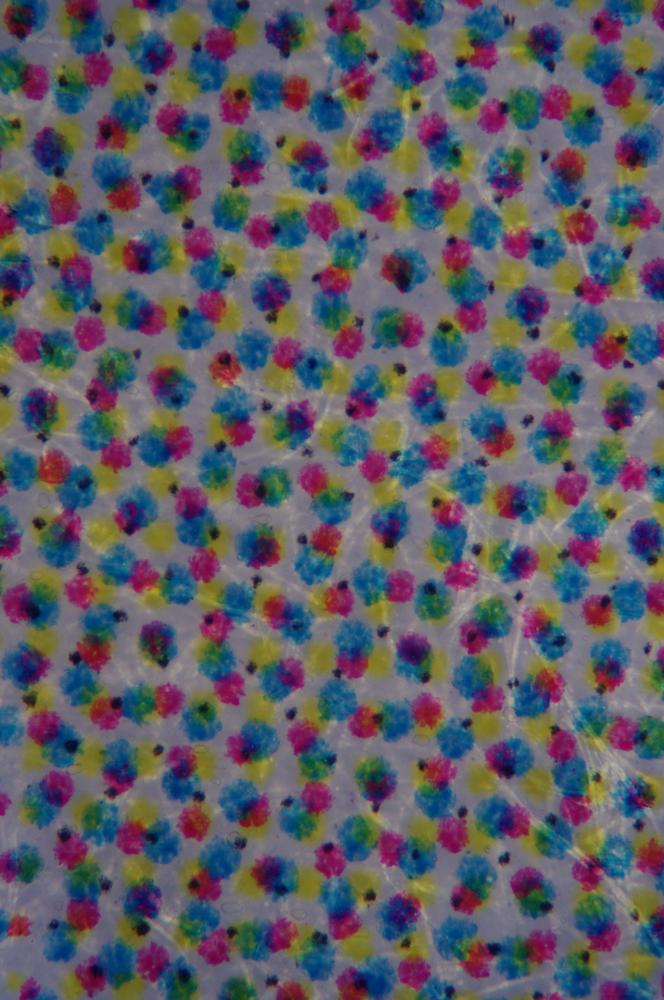
Four-color printing, as used to produce the cover of this book, is done by using a screen to put tiny dots of ink on the page. “Four-color” refers to the CMYK inks (Cyan, Magenta, Yellow, and blacK) used to produce full-color images. These dots of ink are not placed randomly within the image. Instead, they’re printed on a precise grid, shown in Figure 4-5. The separation between the dots of that grid is known precisely. That’s all we need to calibrate our ocular micrometer. We’ll lead you through the process so that you can calibrate your own.
In the dot pattern shown in Figure 4-5, we’d use the black dots for calibrating because they’re much smaller and more sharply defined than the cyan, magenta, and yellow dots.
To calibrate your eyepiece reticle, take the following steps:
Obtain a screen-printed specimen of known resolution. One obvious source is the cover of this book, which is printed at 300 dpi.
Position the specimen under the 4X objective. Use a desk lamp or similar light source to light the specimen from above.
Use the mechanical stage to put the center of one dot on the center of the zero mark on the eyepiece reticle. You can use any color dot. The spacing is the same, so choose whichever color has the smallest, sharpest dots. In Figure 1-4, the small black dots (which are actually the black ink) are the clear choice.
Orient the eyepiece reticle so that a row of the same color dots aligns with the reticle scale. (Not all eyepiece reticles rotate with the eyepiece; if yours does not, you’ll have to realign the specimen on the stage until a row of dots is lined up with the reticle scale.)
Look for a dot near one end of the reticle scale, and count the dots between the initial dot and the furthest dot visible near the other end of the scale. Record the number of dots and the number of scale units between them.
Based on the known resolution of the screen used to produce the image, the number of dots you counted, and the number of scale units between the first dot and the last, calculate the number of μm represented by each reticle unit.
We did the calculations for our microscope, reticle, and specimen as follows:
At 40X, 14 dots, center to center, occupied exactly the full length of the reticle scale, 100 units.
The screen resolution of our print sample was 300 dpi (dots per inch), so those 14 dots represent (14/300) = 0.0467”.
Converting to μm, we multiplied (0.0467” * 25.4 mm/inch * 1000 μm/mm) = 1185 μm.
Since 1185 μm covers 100 reticle scale units, one unit equals (1185 μm / 100 units) = 11.85 μm/unit at 40X.
We repeated the calibration at 100X, as follows:
At 100X, five dots, center to center, occupied 89 reticle scale units. (The sixth dot was within the field of view, but off the end of the scale.)
Again, the screen resolution of our print sample was 300 dpi (dots per inch), so those five dots represent (5/300) = 0.0167”.
Converting to μm, we multiplied (0.0167” * 25.4 mm/inch * 1000 μm/mm) = 423.3 μm.
Since 423.3 μm covers 89 reticle scale units, one unit equals (423.3 μm / 89 units) = 4.757 μm/unit at 100X.
As a sanity check, we multiplied the result at 100X by 2.5 to see how well it corresponded to the calibration at 40X. That gave us (4.757 * 2.5) = 11.89 μm/unit, very close to the 11.85 μm/unit we calculated at 40X. It’s a mistake to expect extreme accuracy from this procedure, so we simply remember that one scale unit corresponds to about 12 μm at 40X, 4.8 μm at 100X, and 1.2 μm at 400X. That’s good enough for any work we’ll do in these lab sessions.
The calibration values you determine will likely differ from ours because your equipment is probably different from ours. But once you obtain good values at 40X and 100X, write them down where you won’t lose them. You’ll use them frequently.
Positioning and Observing a Slide
Turn on the illuminator, open the diaphragm to its widest setting, and rotate the turret to place the 4X objective in position.
Position a prepared slide—ideally one of bacteria or diatoms—on the stage, and secure it with the stage clips or the mechanical stage. Make sure the specimen is centered over the hole in the stage.
Focus critically on the specimen. Adjust the diaphragm setting and illumination brightness and observe the differences visible in the specimen. For example, high brightness may reveal maximum detail in the cell wall but make other internal structures invisible, while lower brightness may do the converse. Note that the setting that produces maximum contrast may not reveal the maximum amount of detail, and vice versa.
Move the slide slightly right and left and up and down and observe the motion through the eyepiece. Does the object you’re observing move in the expected direction or the opposite direction?
Carefully rotate the 10X objective into position and then look through the eyepiece. If your microscope is parfocal (as it should be) then the specimen should already be focused, or nearly so. If necessary, use the fine focus knob to focus critically. Repeat step 3 to observe the differences in the image at different diaphragm and brightness settings.
Repeat step 5 using the 40X (high-and-dry) objective. Make sure that the specimen is centered in the field of view before proceeding to the next step.
Rotate the nosepiece (turret) until it is halfway between the 40X and 100X (oil-immersion) objective. Put one drop of immersion oil on the coverslip. Watching from the side, carefully rotate the 100X objective into position, making sure that it does not contact the coverslip and is immersed in the oil drop.
Adjust the diaphragm and illuminator brightness to reveal maximum detail in the specimen. Record your observations in your lab notebook.
Build a Darkfield Apparatus from Pocket Change
So far in this lab session, we’ve used only bright field illumination, which is all most students and science enthusiasts ever use. Darkfield illumination reveals structural details that are invisible with bright field illumination, and is worth exploring. Fortunately, it’s quick and cheap to set up nearly any compound microscope to use basic darkfield illumination, at least at low to medium magnification.
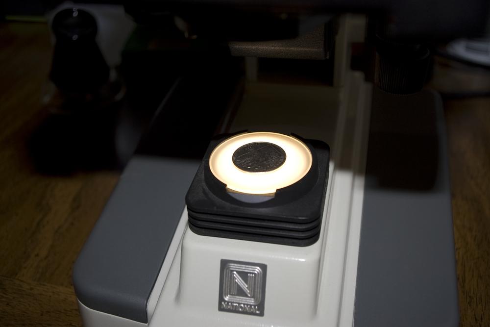
Research-grade (very expensive) microscopes include special darkfield condensers and objectives with lower than standard numerical apertures to optimize darkfield image quality. Although they are not equipped with special darkfield condensers or objectives, some student-grade microscopes include the hardware needed to use basic darkfield illumination, or offer it as an inexpensive option. You can also buy a darkfield assembly for $50 or so that can be used with many standard microscopes, but there’s really no need for it. You can build your own darkfield apparatus in less than a second for pocket change (literally), and get results about as good as you’d get from the $50 apparatus. Figure 4-6 shows you how to do it.
Yep, it’s that easy. Just place a coin in the center of the ground-glass illuminator diffuser disk. (You might want to use a piece of clear plastic or tissue paper to prevent the coin from scratching the disk.) You can experiment with different size coins to find the best size for your own setup.
Once you’ve positioned the coin, place a piece of thin paper on the stage. Turn on the illuminator and adjust the condenser focus and diaphragm opening to produce an annular (doughnut-shaped) light spot. Reposition the coin as necessary to center the dark spot in the bright ring. Replace the paper with a slide you want to observe—ideally an unstained thin section or unstained microorganisms—and get your first look at darkfield illumination.
With many microscopes, the coin method works pretty well with the 4X or 10X objective, but if you want to use darkfield illumination with your 40X objective you’ll need to do a bit more work and spend a few more cents. With a 40X objective, the mask must be be smaller than a coin and closer to the diaphragm and the bottom of the condenser. The filter holder is the obvious location.
You’ll need a piece of glass or thin transparent plastic that fits into or on top of your substage filter holder. You can use an ordinary glass slide, if it fits between the top of the filter holder and the bottom of the diaphragm assembly, or a piece of stiff, transparent plastic. (We used a plastic microscope slide, which for adults is about all plastic microscope slides are good for.)
You’ll also need an opaque, round mask. How big? We can’t say, other than that it must be smaller in diameter than the maximum opening of your microscope’s diaphragm—probably much smaller. Ideally, when it’s focused you want the dark central part inside the bright ring to be just slightly larger than the field of view of your 40X objective, which is probably about 0.5 mm. The size of the mask needed to produce a dark area that size at the focal plane depends on the physical and optical characteristics of your condenser and diaphragm.
We suggest you start by placing the slide you used for testing with the 4X and 10X objectives in the stage. Rotate the 40X objective into position, focus on the bright field image, and adjust the diaphragm opening and condenser focus to provide the best image quality. Once that’s done, you can start testing to determine the proper mask size.
We started with a mask about 6 mm (a quarter inch) in diameter. We used a small sticky label dot, but you can also use a three-hole punch to punch out circles from heavy paper or thin cardboard. Our sticky label was white paper, so we used a black Sharpie marker to color it in. Stick the mask to the plastic or glass slide and position it in the filter holder. Open the diaphragm to its widest setting. Move the mask around until the dark central portion appears in the field of view and then close the diaphragm to cut off all but a thin annulus around the mask. If the dark spot doesn’t cover the entire field of view, you’ll need a larger mask. If the dark central spot is much larger than the field of view, you’ll need a smaller mask. Ideally, you want the mask to produce a dark central spot that’s just slightly larger than the field of view.
Of course, producing a reasonably circular mask of a particular diameter can be difficult. We tried using a black permanent marker to produce tiny black circles, but those circles were neither perfectly round nor completely opaque. Thinking about it, we decided to try using small drops of opaque paint applied with a toothpick, which worked perfectly after a bit of experimentation to produce opaque circles of any size we wanted.
The first thing you’ll notice using darkfield illumination at high magnification is that the image is very dim. That’s unavoidable, because the only light on the specimen is coming from the periphery. You can improve matters somewhat by removing the ground glass illuminator diffuser disk.
Once you have a mask of the proper size, keep it stored safely so that you don’t need to reinvent the mask each time you want to use darkfield illumination at 400X. Unfortunately, it’s not possible to build a field-expedient darkfield apparatus for use with the 100X oil-immersion objective. Or, if it is, we can’t figure out how to do it.
Review Questions
Q1: What relationship does physical movement of a slide have to apparent movement while viewing the slide through the microscope?
Q2: Describe the proper procedure for focusing a microscope. Why is it important to use this procedure?
Q3: What is the relationship between magnification and field of view?
Q4: Your microscope provides magnifications of 40X, 100X, and 400X. Do you need immersion oil? Why or why not?
