Now that you’ve seen how Windows structures the virtual address space, let’s look at how it maps these address spaces to real physical pages. User applications and system code reference virtual addresses. This section starts with a detailed description of 32-bit x86 address translation (in both non-PAE and PAE modes) and continues with a brief description of the differences on the 64-bit IA64 and x64 platforms. In the next section, we’ll describe what happens when such a translation doesn’t resolve to a physical memory address (paging) and explain how Windows manages physical memory via working sets and the page frame database.
Using data structures the memory manager creates and maintains called page tables, the CPU translates virtual addresses into physical addresses. Each page of virtual address space is associated with a system-space structure called a page table entry (PTE), which contains the physical address to which the virtual one is mapped. For example, Figure 10-15 shows how three consecutive virtual pages might be mapped to three physically discontiguous pages on an x86 system. There may not even be any PTEs for regions that have been marked as reserved or committed but never accessed, because the page table itself might be allocated only when the first page fault occurs.
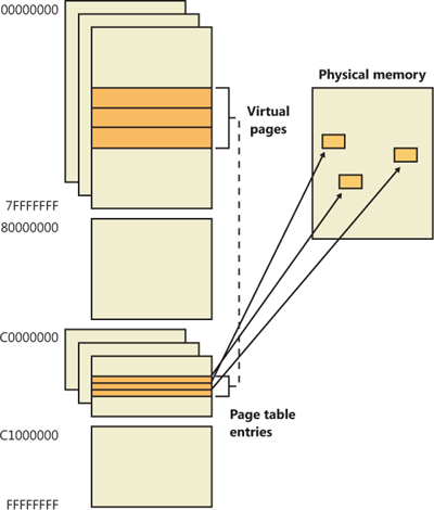
The dashed line connecting the virtual pages to the PTEs in Figure 10-15 represents the indirect relationship between virtual pages and physical memory.
Note
Even kernel-mode code (such as device drivers) cannot reference physical memory addresses directly, but it may do so indirectly by first creating virtual addresses mapped to them. For more information, see the memory descriptor list (MDL) support routines described in the WDK documentation.
As mentioned previously, Windows on x86 can use either of two schemes for address translation: non-PAE and PAE. We’ll discuss the non-PAE mode first and cover PAE in the next section. The PAE material does depend on the non-PAE material, so even if you are primarily interested in PAE, you should study this section first. The description of x64 address translation similarly builds on the PAE information.
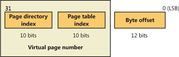
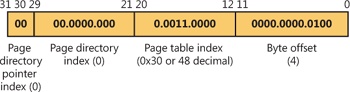
Non-PAE x86 systems use a two-level page table structure to translate virtual to physical addresses. A 32-bit virtual address mapped by a normal 4-KB page is interpreted as two fields: the virtual page number and the byte within the page, called the byte offset. The virtual page number is further divided into two subfields, called the page directory index and the page table index, as illustrated in Figure 10-16. These two fields are used to locate entries in the page directory and in a page table.
The sizes of these bit fields are dictated by the structures they reference. For example, the byte offset is 12 bits because it denotes a byte within a page, and pages are 4,096 bytes (212 = 4,096). The other indexes are 10 bits because the structures they index have 1,024 entries (210 = 1,024).
The job of virtual address translation is to convert these virtual addresses into physical addresses—that is, addresses of locations in RAM. The format of a physical address on an x86 non-PAE system is shown in Figure 10-17.
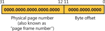
As you can see, the format is very similar to that of a virtual address. Furthermore, the byte offset value from a virtual address will be the same in the resulting physical address. We can say, then, that address translation involves converting virtual page numbers to physical page numbers (also referred to as page frame numbers, or PFNs). The byte offset does not participate in, and does not change as a result of, address translation. It is simply copied from the virtual address to the physical address,
Figure 10-18 shows the relationship of these three values and how they are used to perform address translation.
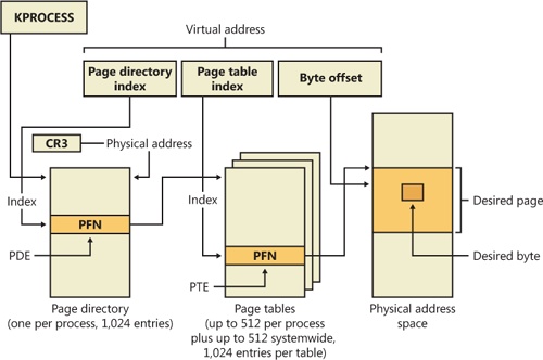
The following basic steps are involved in translating a virtual address:
The memory management unit (MMU) uses a privileged CPU register, CR3, to obtain the physical address of the page directory.
The page directory index portion of the virtual address is used as an index into the page directory. This locates the page directory entry (PDE) that contains the location of the page table needed to map the virtual address. The PDE in turn contains the physical page number, also called the page frame number, or PFN, of the desired page table, provided the page table is resident—page tables can be paged out or not yet created, and in those cases, the page table is first made resident before proceeding. If a flag in the PDE indicates that it describes a large page, then it simply contains the PFN of the target large page, and the rest of the virtual address is treated as the byte offset within the large page.
The page table index is used as an index into the page table to locate the PTE that describes the virtual page in question.
If the PTE’s valid bit is clear, this triggers a page fault (memory management fault). The operating system’s memory management fault handler (pager) locates the page and tries to make it valid; after doing so, this sequence continues at step 5. (See the section Page Fault Handling) If the page cannot or should not be made valid (for example, because of a protection fault), the fault handler generates an access violation or a bug check.
When the PTE describes a valid page (whether immediately or after page fault resolution), the desired physical address is constructed from the PFN field of the PTE, followed by the byte offset field from the original virtual address.
Now that you have the overall picture, let’s look at the detailed structure of page directories, page tables, and PTEs.
On non-PAE x86 systems, each process has a single page directory, a page the memory manager creates to map the location of all page tables for that process. The physical address of the process page directory is stored in the kernel process (KPROCESS) block, but it is also mapped virtually at address 0xC0300000 on x86 non-PAE systems. (For more detailed information about the KPROCESS and other process data structures, refer to Chapter 5, “Processes, Threads, and Jobs” in Part 1.)
The CPU obtains the location of the page directory from a privileged CPU register called CR3. It contains the page frame number of the page directory. (Since the page directory is itself always page-aligned, the low-order 12 bits of its address are always zero, so there is no need for CR3 to supply these.) Each time a context switch occurs to a thread that is in a different process than that of the currently executing thread, the context switch routine in the kernel loads this register from a field in the KPROCESS block of the new process. Context switches between threads in the same process don’t result in reloading the physical address of the page directory because all threads within the same process share the same process address space and thus use the same page directory and page tables.
The page directory is composed of page directory entries (PDEs), each of which is 4 bytes long. The PDEs in the page directory describe the state and location of all the possible page tables for the process. As described later in the chapter, page tables are created on demand, so the page directory for most processes points only to a small set of page tables. (If a page table does not yet exist, the VAD tree is consulted to determine whether an access should materialize it.) The format of a PDE isn’t repeated here because it’s mostly the same as a hardware PTE, which is described shortly.
To describe the full 4-GB virtual address space, 1,024 page tables are required. The process page directory that maps these page tables contains 1,024 PDEs. Therefore, the page directory index needs to be 10 bits wide (210 = 1,024).
Because Windows provides a private address space for each process, each process has its own page directory and page tables to map that process’s private address space. However, the page tables that describe system space are shared among all processes (and session space is shared only among processes in a session). To avoid having multiple page tables describing the same virtual memory, when a process is created, the page directory entries that describe system space are initialized to point to the existing system page tables. If the process is part of a session, session space page tables are also shared by pointing the session space page directory entries to the existing session page tables.
Each page directory entry points to a page table. A page table is a simple array of PTEs. The virtual address’s page table index field (as shown in Figure 10-18) indicates which PTE within the page table corresponds to and describes the data page in question. The page table index is 10 bits wide, allowing you to reference up to 1,024 4-byte PTEs. Of course, because x86 provides a 4-GB virtual address space, more than one page table is needed to map the entire address space. To calculate the number of page tables required to map the entire 4-GB virtual address space, divide 4 GB by the virtual memory mapped by a single page table. Recall that each page table on an x86 system maps 4 MB of data pages. Thus, 1,024 page tables (4 GB / 4 MB) are required to map the full 4-GB address space. This corresponds with the 1,024 entries in the page directory.
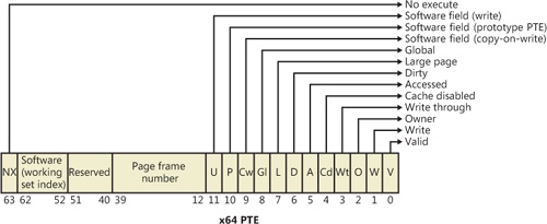
You can use the !pte command in the kernel debugger to examine PTEs. (See the experiment EXPERIMENT: Translating Addresses) We’ll discuss valid PTEs here and invalid PTEs in a later section. Valid PTEs have two main fields: the page frame number (PFN) of the physical page containing the data or of the physical address of a page in memory, and some flags that describe the state and protection of the page, as shown in Figure 10-19.
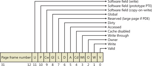
As you’ll see later, the bits labeled “Software field” and “Reserved” in Figure 10-19 are ignored by the MMU, whether or not the PTE is valid. These bits are stored and interpreted by the memory manager. Table 10-11 briefly describes the hardware-defined bits in a valid PTE.
Table 10-11. PTE Status and Protection Bits
Name of Bit | Meaning |
|---|---|
Accessed | Page has been accessed. |
Disables CPU caching for that page. | |
Page is using copy-on-write (described earlier). | |
Page has been written to. | |
Translation applies to all processes. (For example, a translation buffer flush won’t affect this PTE.) | |
Indicates that the PDE maps a 4-MB page (or 2 MB on PAE systems). See the section Large and Small Pages earlier in the chapter. | |
Indicates whether user-mode code can access the page or whether the page is limited to kernel-mode access. | |
The PTE is a prototype PTE, which is used as a template to describe shared memory associated with section objects. | |
Valid | Indicates whether the translation maps to a page in physical memory. |
Marks the page as write-through or (if the processor supports the page attribute table) write-combined. This is typically used to map video frame buffer memory. | |
Write | Indicates to the MMU whether the page is writable. |
On x86 systems, a hardware PTE contains two bits that can be changed by the MMU, the Dirty bit and the Accessed bit. The MMU sets the Accessed bit whenever the page is read or written (provided it is not already set). The MMU sets the Dirty bit whenever a write operation occurs to the page. The operating system is responsible for clearing these bits at the appropriate times; they are never cleared by the MMU.
The x86 MMU uses a Write bit to provide page protection. When this bit is clear, the page is read-only; when it is set, the page is read/write. If a thread attempts to write to a page with the Write bit clear, a memory management exception occurs, and the memory manager’s access fault handler (described later in the chapter) must determine whether the thread can be allowed to write to the page (for example, if the page was really marked copy-on-write) or whether an access violation should be generated.
The additional Write bit implemented in software (as mentioned in Table 10-11) is used to force updating of the Dirty bit to be synchronized with updates to Windows memory management data. In a simple implementation, the memory manager would set the hardware Write bit (bit 1) for any writable page, and a write to any such page will cause the MMU to set the Dirty bit in the page table entry. Later, the Dirty bit will tell the memory manager that the contents of that physical page must be written to backing store before the physical page can be used for something else.
In practice, on multiprocessor systems, this can lead to race conditions that are expensive to resolve. The MMUs of the various processors can, at any time, set the Dirty bit of any PTE that has its hardware Write bit set. The memory manager must, at various times, update the process working set list to reflect the state of the Dirty bit in a PTE. The memory manager uses a pushlock to synchronize access to the working set list. But on a multiprocessor system, even while one processor is holding the lock, the Dirty bit might be changed by MMUs of other CPUs. This raises the possibility of missing an update to a Dirty bit.
To avoid this, the Windows memory manager initializes both read-only and writable pages with the hardware Write bit (bit 1) of their PTEs set to 0 and records the true writable state of the page in the software Write bit (bit 11). On the first write access to such a page, the processor will raise a memory management exception because the hardware Write bit is clear, just as it would be for a true read-only page. In this case, though, the memory manager learns that the page actually is writable (via the software Write bit), acquires the working set pushlock, sets the Dirty bit and the hardware Write bit in the PTE, updates the working set list to note that the page has been changed, releases the working set pushlock, and dismisses the exception. The hardware write operation then proceeds as usual, but the setting of the Dirty bit is made to happen with the working set list pushlock held.
On subsequent writes to the page, no exceptions occur because the hardware Write bit is set. The MMU will redundantly set the Dirty bit, but this is benign because the “written-to” state of the page is already recorded in the working set list. Forcing the first write to a page to go through this exception handling may seem to be excessive overhead. However, it happens only once per writable page as long as the page remains valid. Furthermore, the first access to almost any page already goes through memory management exception handling because pages are usually initialized in the invalid state (PTE bit 0 is clear). If the first access to a page is also the first write access to the page, the Dirty bit handling just described will occur within the handling of the first-access page fault, so the additional overhead is small. Finally, on both uniprocessor and multiprocessor systems, this implementation allows flushing of the translation look-aside buffer (described later) without holding a lock for each page being flushed.
Once the memory manager has determined the physical page number, it must locate the requested data within that page. This is the purpose of the byte offset field. The byte offset from the original virtual address is simply copied to the corresponding field in the physical address. On x86 systems, the byte offset is 12 bits wide, allowing you to reference up to 4,096 bytes of data (the size of a page). Another way to interpret this is that the byte offset from the virtual address is concatenated to the physical page number retrieved from the PTE. This completes the translation of a virtual address to a physical address.
As you’ve learned so far, each hardware address translation requires two lookups: one to find the right entry in the page directory (which provides the location of the page table) and one to find the right entry in the page table. Because doing two additional memory lookups for every reference to a virtual address would triple the required bandwidth to memory, resulting in poor performance, all CPUs cache address translations so that repeated accesses to the same addresses don’t have to be repeatedly translated. This cache is an array of associative memory called the translation look-aside buffer, or TLB. Associative memory is a vector whose cells can be read simultaneously and compared to a target value. In the case of the TLB, the vector contains the virtual-to-physical page mappings of the most recently used pages, as shown in Figure 10-20, and the type of page protection, size, attributes, and so on applied to each page. Each entry in the TLB is like a cache entry whose tag holds portions of the virtual address and whose data portion holds a physical page number, protection field, valid bit, and usually a dirty bit indicating the condition of the page to which the cached PTE corresponds. If a PTE’s global bit is set (as is done by Windows for system space pages that are visible to all processes), the TLB entry isn’t invalidated on process context switches.
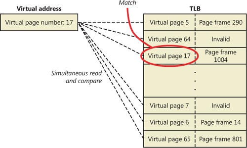
Virtual addresses that are used frequently are likely to have entries in the TLB, which provides extremely fast virtual-to-physical address translation and, therefore, fast memory access. If a virtual address isn’t in the TLB, it might still be in memory, but multiple memory accesses are needed to find it, which makes the access time slightly slower. If a virtual page has been paged out of memory or if the memory manager changes the PTE, the memory manager is required to explicitly invalidate the TLB entry. If a process accesses it again, a page fault occurs, and the memory manager brings the page back into memory (if needed) and re-creates its PTE entry (which then results in an entry for it in the TLB).
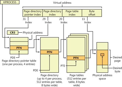
The Intel x86 Pentium Pro processor introduced a memory-mapping mode called Physical Address Extension (PAE). With the proper chipset, the PAE mode allows 32-bit operating systems access to up to 64 GB of physical memory on current Intel x86 processors (up from 4 GB without PAE) and up to 1,024 GB of physical memory when running on x64 processors in legacy mode (although Windows currently limits this to 64 GB due to the size of the PFN database required to describe so much memory). When the processor is running in PAE mode, the memory management unit (MMU) divides virtual addresses mapped by normal pages into four fields, as shown in Figure 10-21. The MMU still implements page directories and page tables, but under PAE a third level, the page directory pointer table, exists above them.
One way in which 32-bit applications can take advantage of such large memory configurations is described in the earlier section Address Windowing Extensions. However, even if applications are not using such functions, the memory manager will use all available physical memory for multiple processes’ working sets, file cache, and trimmed private data through the use of the system cache, standby, and modified lists (described in the section Page Frame Number Database).
PAE mode is selected at boot time and cannot be changed without rebooting. As explained in Chapter 2 in Part 1, there is a special version of the 32-bit Windows kernel with support for PAE called Ntkrnlpa.exe. Thirty-two-bit systems that have hardware support for nonexecutable memory (described earlier, in the section No Execute Page Protection) are booted by default using this PAE kernel, because PAE mode is required to implement the no-execute feature. To force the loading of the PAE-enabled kernel, you can set the pae BCD option to ForceEnable.
Note that the PAE kernel is installed on the disk on all 32-bit Windows systems, even systems with small memory and without hardware no-execute support. This is to allow testing of PAE-related code, even on small memory systems, and to avoid the need for reinstalling Windows should more RAM be added later. Another BCD option relevant to PAE is nolowmem, which discards memory below 4 GB (assuming you have at least 5 GB of physical memory) and relocates device drivers above this range. This guarantees that drivers will be presented with physical addresses greater than 32 bits, which makes any possible driver sign extension bugs easier to find.
To understand PAE, it is useful to understand the derivation of the sizes of the various structures and bit fields. Recall that the goal of PAE is to allow addressing of more than 4 GB of RAM. The 4-GB limit for RAM addresses without PAE comes from the 12-bit byte offset and the 20-bit page frame number fields of physical addresses: 12 + 20 = 32 bits of physical address, and 232bytes = 4 GB. (Note that this is due to a limit of the physical address format and the number of bits allocated for the PFN within a page table entry. The fact that virtual addresses are 32 bits wide on x86, with or without PAE, does not limit the physical address space.)
Under PAE, the PFN is expanded to 24 bits. Combined with the 12-bit byte offset, this allows addressing of 224 + 12 bytes, or 64 GB, of memory.
To provide the 24-bit PFN, PAE expands the PFN fields of page table and page directory entries from 20 to 24 bits. To allow room for this expansion, the page table and page directory entries are 8 bytes wide instead of 4. (This would seem to expand the PFN field of the PTE and PDE by 32 bits rather than just 4, but in x86 processors, PFNs are limited to 24 bits. This does leave a large number of bits in the PDE unused—or, rather, available for future expansion.)
Since both page tables and page directories have to fit in one page, these tables can then have only 512 entries instead of 1,024. So the corresponding index fields of the virtual address are accordingly reduced from 10 to 9 bits.
This then leaves the two high-order bits of the virtual address unaccounted for. So PAE expands the number of page directories from one to four and adds a third-level address translation table, called the page directory pointer table, or PDPT. This table contains only four entries, 8 bytes each, which provide the PFNs of the four page directories. The two high-order bits of the virtual address are used to index into the PDPT and are called the page directory pointer index.
As before, CR3 provides the location of the top-level table, but that is now the PDPT rather than the page directory. The PDPT must be aligned on a 32-byte boundary and must furthermore reside in the first 4 GB of RAM (because CR3 on x86 is only a 32-bit register, even with PAE enabled).
Note that PAE mode can address more memory than the standard translation mode not directly because of the extra level of translation, but because the physical address format has been expanded. The extra level of translation is required to allow processing of all 32 bits of a virtual address.
EXPERIMENT: Translating Addresses
To clarify how address translation works, this experiment shows a real example of translating a virtual address on an x86 PAE system, using the available tools in the kernel debugger to examine the PDPT, page directories, page tables, and PTEs. (It is common for Windows on today’s x86 processors, even with less than 4 GB of RAM, to run in PAE mode because PAE mode is required to enable no-execute memory access protection.) In this example, we’ll work with a process that has virtual address 0x30004, currently mapped to a valid physical address. In later examples, you’ll see how to follow address translation for invalid addresses with the kernel debugger.
First let’s convert 0x30004 to binary and break it into the three fields that are used to translate an address. In binary, 0x30004 is 11.0000.0000.0000.0100. Breaking it into the component fields yields the following:
To start the translation process, the CPU needs the physical address of the process’s page directory pointer table, found in the CR3 register while a thread in that process is running. You can display this address by looking at the DirBase field in the output of the !process command, as shown here:
lkd> !process -1 0
PROCESS 852d1030  SessionId: 1  Cid: 0dec    Peb: 7ffdf000  ParentCid: 05e8
    DirBase: ced25440  ObjectTable: a2014a08  HandleCount: 221.
    Image: windbg.exe
The DirBase field shows that the page directory pointer table is at physical address 0xced25440. As shown in the preceding illustration, the page directory pointer table index field in our example virtual address is 0. Therefore, the PDPT entry that contains the physical address of the relevant page directory is the first entry in the PDPT, at physical address 0xced25440.
As under x86 non-PAE systems, the kernel debugger !pte command displays the PDE and PTE that describe a virtual address, as shown here:
lkd> !pte 30004
                    VA 00030004
PDE at C0600000            PTE at C0000180
contains 000000002EBF3867  contains 800000005AF4D025
pfn 2ebf3     ---DA--UWEV   pfn 5af4d     ----A--UR-V
The debugger does not show the page directory pointer table, but it is easy to display given its physical address:
lkd> !dq ced25440 L 4
#ced25440 00000000`2e8ff801 00000000`2c9d8801
#ced25450 00000000`2e6b1801 00000000`2e73a801
Here we have used the debugger extension command !dq. This is similar to the dq command (display as quadwords—“quadwords” being a name for a 64-bit field; this came from the day when “words” were often 16 bits), but it lets us examine memory by physical rather than virtual address. Since we know that the PDPT is only four entries long, we added the L 4 length argument to keep the output uncluttered.
As illustrated previously, the PDPT index (the two most significant bits) from our example virtual address equal 0, so the PDPT entry we want is the first displayed quadword. PDPT entries have a format similar to PD entries and PT entries, so we can see by inspection that this one contains a PFN of 0x2e8ff, for a physical address of 2e8ff000. That’s the physical address of the page directory.
The !pte output shows the PDE address as a virtual address, not physical. On x86 systems with PAE, the first process page directory starts at virtual address 0xC0600000. The page directory index field of our example virtual address is 0, so we’re looking at the first PDE in the page directory. Therefore, in this case, the PDE address is the same as the page directory address.
As with non-PAE, the page directory entry provides the PFN of the needed page table; in this example, the PFN is 0x2ebf3. So the page table starts at physical address 0x2ebf3000. To this the MMU will add the page table index field (0x30) from the virtual address, multiplied by 8 (the size of a PTE in bytes; this would be 4 on a non-PAE system). The resulting physical address of the PTE is then 0x2ebf3180.
The debugger shows that this PTE is at virtual address 0xC0000180. Notice that the byte offset portion (0x180) is the same as that from the physical address, as is always the case in address translation. Because the memory manager maps page tables starting at 0xC0000000, adding 0x180 to 0xC0000000 yields the virtual address shown in the kernel debugger output: 0xC0000180. The debugger shows that the PFN field of the PTE is 0x5af4d.
Finally, we can consider the byte offset from the original address. As described previously, the MMU will concatenate the byte offset to the PFN from the PTE, giving a physical address of 0x5af4d004. This is the physical address that corresponds to the original virtual address of 0x30004—at the moment.
The flags bits from the PTE are interpreted to the right of the PFN number. For example, the PTE that describes the page being referenced has flags of --A--UR-V. Here, A stands for accessed (the page has been read), U for user-mode accessible (as opposed to kernel-mode accessible only), R for read-only page (rather than writable), and V for valid (the PTE represents a valid page in physical memory).
To confirm our calculation of the physical address, we can look at the memory in question via both its virtual and its physical addresses. First, using the debugger’s dd command (display dwords) on the virtual address, we see the following:
lkd> dd 30004
00030004  00000020 00000001 00003020 000000dc
00030014  00000000 00000020 00000000 00000014
00030024  00000001 00000007 00000034 0000017c
00030034  00000001 00000000 00000000 00000000
00030044  00000000 00000000 00000002 1a26ef4e
00030054  00000298 00000044 000002e0 00000260
00030064  00000000 f33271ba 00000540 0000004a
00030074  0000058c 0000031e 00000000 2d59495b
And with the !dd command on the physical address just computed, we see the same contents:
lkd> !dd 5af4d004
#5af4d004 00000020 00000001 00003020 000000dc
#5af4d014 00000000 00000020 00000000 00000014
#5af4d024 00000001 00000007 00000034 0000017c
#5af4d034 00000001 00000000 00000000 00000000
#5af4d044 00000000 00000000 00000002 1a26ef4e
#5af4d054 00000298 00000044 000002e0 00000260
#5af4d064 00000000 f33271ba 00000540 0000004a
#5af4d074 0000058c 0000031e 00000000 2d59495b
We could similarly compare the displays from the virtual and physical addresses of the PTE and PDE.
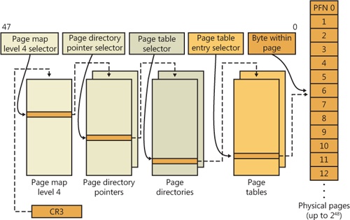
Address translation on x64 is similar to x86 PAE, but with a fourth level added. Each process has a top-level extended page directory (called the page map level 4 table) that contains the physical locations of 512 third-level structures, called page parent directories. The page parent directory is analogous to the x86 PAE page directory pointer table, but there are 512 of them instead of just 1, and each page parent directory is an entire page, containing 512 entries instead of just 4. Like the PDPT, the page parent directory’s entries contain the physical locations of second-level page directories, each of which in turn contains 512 entries providing the locations of the individual page tables. Finally, the page tables (each of which contain 512 page table entries) contain the physical locations of the pages in memory. (All of the “physical locations” in the preceding description are stored in these structures as page frame numbers, or PFNs.)
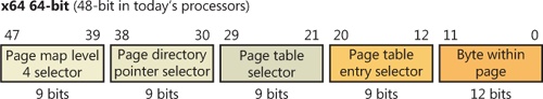
Current implementations of the x64 architecture limit virtual addresses to 48 bits. The components that make up this 48-bit virtual address are shown in Figure 10-22. The connections between these structures are shown in Figure 10-23. Finally, the format of an x64 hardware page table entry is shown in Figure 10-24.
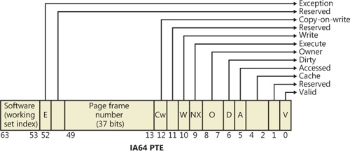
The virtual address space for IA64 is divided into eight regions by the hardware. Each region can have its own set of page tables. Windows uses five of the regions, three of which have page tables. Table 10-12 lists the regions and how they are used.
Table 10-12. The IA64 Regions
Address translation by 64-bit Windows on the IA64 platform uses a three-level page table scheme. Each process has a page directory pointer structure that contains 1,024 pointers to page directories. Each page directory contains 1,024 pointers to page tables, which in turn point to physical pages. Figure 10-25 shows the format of an IA64 hardware PTE.