In several previous sections, we’ve concentrated on the virtual view of a Windows process—page tables, PTEs, and VADs. In the remainder of this chapter, we’ll explain how Windows manages physical memory, starting with how Windows keeps track of physical memory. Whereas working sets describe the resident pages owned by a process or the system, the page frame number (PFN) database describes the state of each page in physical memory. The page states are listed in Table 10-16.
Table 10-16. Page States
Status | Description |
|---|---|
The page is part of a working set (either a process working set, a session working set, or a system working set), or it’s not in any working set (for example, nonpaged kernel page) and a valid PTE usually points to it. | |
A temporary state for a page that isn’t owned by a working set and isn’t on any paging list. A page is in this state when an I/O to the page is in progress. The PTE is encoded so that collided page faults can be recognized and handled properly. (Note that this use of the term “transition” differs from the use of the word in the section on invalid PTEs; an invalid transition PTE refers to a page on the standby or modified list.) | |
Standby | The page previously belonged to a working set but was removed (or was prefetched/clustered directly into the standby list). The page wasn’t modified since it was last written to disk. The PTE still refers to the physical page but is marked invalid and in transition. |
Modified | The page previously belonged to a working set but was removed. However, the page was modified while it was in use and its current contents haven’t yet been written to disk or remote storage. The PTE still refers to the physical page but is marked invalid and in transition. It must be written to the backing store before the physical page can be reused. |
Same as a modified page, except that the page has been marked so that the memory manager’s modified page writer won’t write it to disk. The cache manager marks pages as modified no-write at the request of file system drivers. For example, NTFS uses this state for pages containing file system metadata so that it can first ensure that transaction log entries are flushed to disk before the pages they are protecting are written to disk. (NTFS transaction logging is explained in Chapter 12.) | |
The page is free but has unspecified dirty data in it. (These pages can’t be given as a user page to a user process without being initialized with zeros, for security reasons.) | |
The page is free and has been initialized with zeros by the zero page thread (or was determined to already contain zeros). | |
The page has generated parity or other hardware errors and can’t be used. |
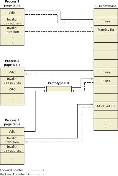
The PFN database consists of an array of structures that represent each physical page of memory on the system. The PFN database and its relationship to page tables are shown in Figure 10-37. As this figure shows, valid PTEs usually point to entries in the PFN database, and the PFN database entries (for nonprototype PFNs) point back to the page table that is using them (if it is being used by a page table). For prototype PFNs, they point back to the prototype PTE.
Of the page states listed in Table 10-16, six are organized into linked lists so that the memory manager can quickly locate pages of a specific type. (Active/valid pages, transition pages, and overloaded “bad” pages aren’t in any systemwide page list.) Additionally, the standby state is actually associated with eight different lists ordered by priority (we’ll talk about page priority later in this section). Figure 10-38 shows an example of how these entries are linked together.
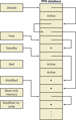
In the next section, you’ll find out how these linked lists are used to satisfy page faults and how pages move to and from the various lists.
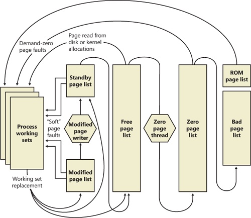
Figure 10-39 shows a state diagram for page frame transitions. For simplicity, the modified-no-write list isn’t shown.
Page frames move between the paging lists in the following ways:
When the memory manager needs a zero-initialized page to service a demand-zero page fault (a reference to a page that is defined to be all zeros or to a user-mode committed private page that has never been accessed), it first attempts to get one from the zero page list. If the list is empty, it gets one from the free page list and zeroes the page. If the free list is empty, it goes to the standby list and zeroes that page.
One reason zero-initialized pages are required is to meet various security requirements, such as the Common Criteria. Most Common Criteria profiles specify that user-mode processes must be given initialized page frames to prevent them from reading a previous process’s memory contents. Therefore, the memory manager gives user-mode processes zeroed page frames unless the page is being read in from a backing store. If that’s the case, the memory manager prefers to use nonzeroed page frames, initializing them with the data off the disk or remote storage.
The zero page list is populated from the free list by a system thread called the zero page thread (thread 0 in the System process). The zero page thread waits on a gate object to signal it to go to work. When the free list has eight or more pages, this gate is signaled. However, the zero page thread will run only if at least one processor has no other threads running, because the zero page thread runs at priority 0 and the lowest priority that a user thread can be set to is 1.
Note
Because the zero page thread actually waits on an event dispatcher object, it receives a priority boost (see the section “Priority Boosts” in Chapter 5 in Part 1), which results in it executing at priority 1 for at least part of the time. This is a bug in the current implementation.
Note
When memory needs to be zeroed as a result of a physical page allocation by a driver that calls MmAllocatePagesForMdl or MmAllocatePagesForMdlEx, by a Windows application that calls AllocateUserPhysicalPages or AllocateUserPhysicalPagesNuma, or when an application allocates large pages, the memory manager zeroes the memory by using a higher performing function called MiZeroInParallel that maps larger regions than the zero page thread, which only zeroes a page at a time. In addition, on multiprocessor systems, the memory manager creates additional system threads to perform the zeroing in parallel (and in a NUMA-optimized fashion on NUMA platforms).
When the memory manager doesn’t require a zero-initialized page, it goes first to the free list. If that’s empty, it goes to the zeroed list. If the zeroed list is empty, it goes to the standby lists. Before the memory manager can use a page frame from the standby lists, it must first backtrack and remove the reference from the invalid PTE (or prototype PTE) that still points to the page frame. Because entries in the PFN database contain pointers back to the previous user’s page table page (or to a page of prototype PTE pool for shared pages), the memory manager can quickly find the PTE and make the appropriate change.
When a process has to give up a page out of its working set (either because it referenced a new page and its working set was full or the memory manager trimmed its working set), the page goes to the standby lists if the page was clean (not modified) or to the modified list if the page was modified while it was resident.
When a process exits, all the private pages go to the free list. Also, when the last reference to a page-file-backed section is closed, and the section has no remaining mapped views, these pages also go to the free list.
EXPERIMENT: The Free and Zero Page Lists
You can observe the release of private pages at process exit with Process Explorer’s System Information display. Begin by creating a process with a large number of private pages in its working set. We did this in an earlier experiment with the TestLimit utility:
C:\temp>testlimit -d 1 -c 800

Testlimit v5.1 - test Windows limits
Copyright (C) 2012 Mark Russinovich
Sysinternals - wwww.sysinternals.com

Leaking private bytes 1 MB at a time ...
Leaked 800 MB of private memory (800 MB total leaked). Lasterror: 0
The operation completed successfully.
The –d option causes TestLimit to not only allocate the memory as private committed, but to “touch” it—that is, to access it. This causes physical memory to be allocated and assigned to the process to realize the area of private committed virtual memory. If there is sufficient available RAM on the system, the entire 800 MB should be in RAM for the process.
This process will now wait until you cause it to exit or terminate (perhaps by using Ctrl+C in its command window). Open Process Explorer and select View, System Information. Observe the Free and Zeroed list sizes.
Now terminate or exit the TestLimit process. You may see the free page list briefly increase in size:
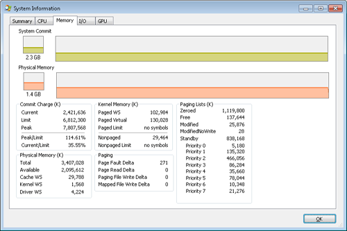
We say “may” because the zero page thread is awakened as soon as there are only eight pages on the zero list, and it acts very quickly. Notice that in this example, we freed 800 MB of private memory but only about 138 MB appear here on the free list. Process Explorer updates this display only once per second, and it is likely that the rest of the pages were already zeroed and moved to the zeroed page list before it happened to “catch” this state.
If you are able to see the temporary increase in the free list, you will then see it drop to zero, and a corresponding increase will occur in the zeroed page list. If not, you will simply see the increase in the zeroed list.
EXPERIMENT: The Modified and Standby Page Lists
The movement of pages from process working set to the modified page list and then to the standby page list can also be observed with the Sysinternals tools VMMap and RAMMap and the live kernel debugger.
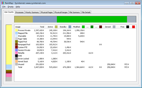
The first step is to open RAMMap and observe the state of the quiet system:
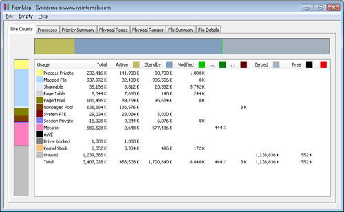
This is an x86 system with about 3.4 GB of RAM usable by Windows. The columns in this display represent the various page states shown in Figure 10-39. (A few of the columns not important to this discussion have been narrowed for ease of reference.)
The system has about 1.2 GB of RAM free (sum of the free and zeroed page lists). About 1,700 MB is on the standby list (hence part of “available,” but likely containing data recently lost from processes or being used by Superfetch). About 448 MB is “active,” being mapped directly to virtual addresses via valid page table entries.
Each row further breaks down into page state by usage or origin (process private, mapped file, and so on). For example, at the moment, of the active 448 MB, about 138 MB is due to process private allocations.
Now, as in the previous experiment, use the TestLimit utility to create a process with a large number of pages in its working set. Again we will use the –d option to cause TestLimit to write to each page, but this time we will use it without a limit, so as to create as many private modified pages as possible:
C:\Users\user1>testlimit -d

Testlimit v5.21 - test Windows limits
Copyright (C) 2012 Mark Russinovich
Sysinternals - www.sysinternals.com

Process ID: 1000

Leaking private bytes with touch (MB) ...
Leaked 2017 MB of private memory (2017 MB total leaked). Lasterror: 8
Not enough storage is available to process this command.
TestLimit has now created 2,017 allocations of 1 MB each.
In RAMMap, use the File, Refresh command to update the display (because of the cost of gathering its information, RAMMap does not update continuously).
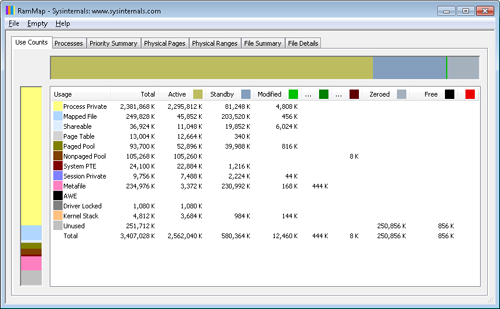
You will see that over 2 GB are now active and in the Process Private row. This is due to the memory allocated and accessed by the TestLimit process. Note also that the standby, zeroed, and free lists are now much smaller. Most of the RAM allocated to TestLimit came from these lists.
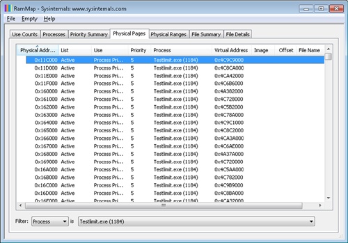
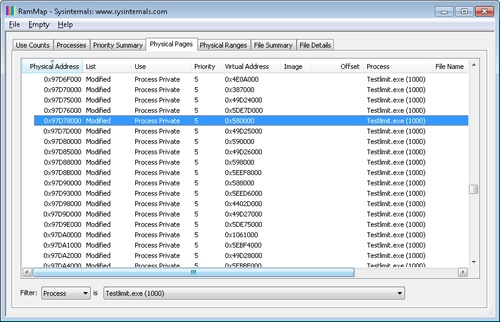
Next, in RAMMap, check the process’s physical page allocations. Change to the Physical Pages tab, and set the filter at the bottom to the column Process and the value Testlimit.exe. This display shows all the physical pages that are part of the process working set.
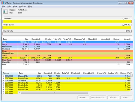
We would like to identify a physical page involved in the allocation of virtual address space done by TestLimit’s –d option. RAMMap does not give an indication about which virtual allocations are associated with RAMMap’s VirtualAlloc calls. However, we can get a good hint of this through the VMMap tool. Using VMMap on the same process, we find the following:
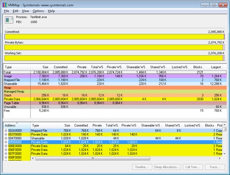
In the lower part of the display, we find hundreds of allocations of process private data, each 1 MB in size and with 1 MB committed. These match the size of the allocations done by TestLimit. The first of these is highlighted in the preceding screen shot. Note the starting virtual address, 0x580000.
Now go back to RAMMap’s physical memory display. Arrange the columns to make the Virtual Address column easily visible, click on it to sort by that value, and you can find that virtual address:
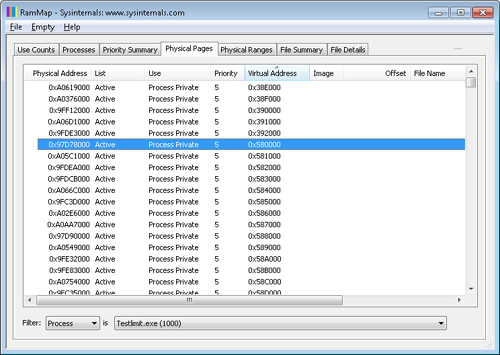
This shows that the virtual page starting at 0x01340000 is currently mapped to physical address 0x97D78000.
TestLimit’s –d option writes the program’s own name to the first bytes of each allocation. We can demonstrate this with the !dc (display characters using physical address) command in the local kernel debugger:
lkd> !dc 0x97d78000
#97d78000 74736554 696d694c 00000074 00000000 TestLimit.......
#97d78010 00000000 00000000 00000000 00000000 ................
#97d78020 00000000 00000000 00000000 00000000 ................
...
For the final leg of the experiment, we will demonstrate that this data remains intact (for a while, anyway) after the process working set is reduced and this page is moved to the modified and then the standby page list.
In VMMap, having selected the TestLimit process, use the View, Empty Working Set command to reduce the process’s working set to the bare minimum. VMMap’s display should now look like this:
Notice that the Working Set bar graph is practically empty. In the middle section, the process shows a total working set of only 9 MB, and almost all of it is in page tables, with a tiny 32 KB total paged in of image files and private data. Now return to RAMMap. On the Use Counts tab, you will find that active pages have been reduced tremendously, with a large number of pages on the modified list and a significant number on the standby list:
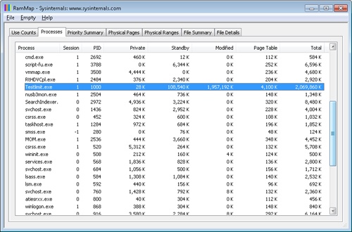
RAMMap’s Processes tab confirms that the TestLimit process contributed most of those pages to those lists:
Still in RAMMap, show the Physical Pages tab. Sort by Physical Address, and find the page previously examined (in this case, physical address 0xc09fa000). RAMMap will almost certainly show that it is on the standby or modified list.
Note that the page is still associated with the TestLimit process and with its virtual address.
Finally, we can again use the kernel debugger to verify the page has not been overwritten:
lkd> !dc 0x97d78000
#97d78000 74736554 696d694c 00000074 00000000 TestLimit.......
#97d78010 00000000 00000000 00000000 00000000 ................
#97d78020 00000000 00000000 00000000 00000000 ................
...
We can also use the local kernel debugger to show the page frame number, or PFN, entry for the page. (The PFN database is described earlier in the chapter.)
lkd> !pfn 97d78
    PFN 00097D78 at address 84E9B920
    flink       000A0604  blink / share count 000A05C1  pteaddress C0002C00
    reference count 0000   Cached     color 0   Priority 5
    restore pte 00000080  containing page        097D60  Modified   M
    Modified
Note that the page is still associated with the TestLimit process and with its virtual address.
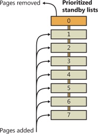
Every physical page in the system has a page priority value assigned to it by the memory manager. The page priority is a number in the range 0 to 7. Its main purpose is to determine the order in which pages are consumed from the standby list. The memory manager divides the standby list into eight sublists that each store pages of a particular priority. When the memory manager wants to take a page from the standby list, it takes pages from low-priority lists first, as shown in Figure 10-40.
Each thread and process in the system is also assigned a page priority. A page’s priority usually reflects the page priority of the thread that first causes its allocation. (If the page is shared, it reflects the highest page priority among the sharing threads.) A thread inherits its page-priority value from the process to which it belongs. The memory manager uses low priorities for pages it reads from disk speculatively when anticipating a process’s memory accesses.
By default, processes have a page-priority value of 5, but functions allow applications and the system to change process and thread page-priority values. You can look at the memory priority of a thread with Process Explorer (per-page priority can be displayed by looking at the PFN entries, as you’ll see in an experiment later in the chapter). Figure 10-41 shows Process Explorer’s Threads tab displaying information about Winlogon’s main thread. Although the thread priority itself is high, the memory priority is still the standard 5.
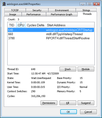
The real power of memory priorities is realized only when the relative priorities of pages are understood at a high level, which is the role of Superfetch, covered at the end of this chapter.
EXPERIMENT: Viewing the Prioritized Standby Lists
You can use the MemInfo tool from Winsider Seminars & Solutions to dump the size of each standby paging list by using the –c flag. MemInfo will also display the number of repurposed pages for each standby list—this corresponds to the number of pages in each list that had to be reused to satisfy a memory allocation, and thus thrown out of the standby page lists. The following is the relevant output from the following command.
C:\Windows\system32>meminfo -c
MemInfo v2.10 - Show PFN database information
Copyright (C) 2007-2009 Alex Ionescu
www.alex-ionescu.com

Initializing PFN Database... Done


Priority               Standby            Repurposed
0 - Idle             0 (      0 KB)        0 (      0 KB)
1 - Very Low     41352 ( 165408 KB)        0 (      0 KB)
2 - Low           7201 (  28804 KB)        0 (      0 KB)
3 - Background    2043 (   8172 KB)        0 (      0 KB)
4 - Background   24715 (  98860 KB)        0 (      0 KB)
5 - Normal        7895 (  31580 KB)        0 (      0 KB)
6 - Superfetch   23877 (  95508 KB)        0 (      0 KB)
7 - Superfetch    8435 (  33740 KB)        0 (      0 KB)
TOTAL           115518 ( 462072 KB)        0 (      0 KB)
You can add the –i flag to MemInfo to continuously display the state of the standby page lists and repurpose counts, which is useful for tracking memory usage as well as the following experiment. Additionally, the System Information panel in Process Explorer (choose View, System Information) can also be used to display the live state of the prioritized standby lists, as shown in this screen shot:
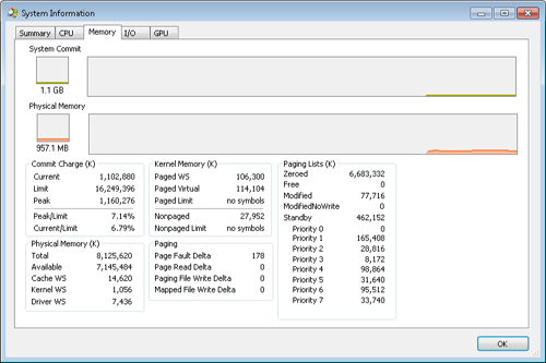
On the recently started x64 system used in this experiment (see the previous MemInfo output), there is no data cached at priority 0, about 165 MB at priority 1, and about 29 MB at priority 2. Your system probably has some data in those priorities as well.
The following shows what happens when we use the TestLimit tool from Sysinternals to commit and touch 1 GB of memory. Here is the command you use (to leak and touch memory in 20 chunks of 50 MB):
testlimit -d 50 -c 20
Here is the output of MemInfo just before the run:
Priority               Standby            Repurposed
0 - Idle             0 (      0 KB)    2554 (  10216 KB)
1 - Very Low     92915 ( 371660 KB)  141352 ( 565408 KB)
2 - Low          35783 ( 143132 KB)       0 (      0 KB)
3 - Background   50666 ( 202664 KB)       0 (      0 KB)
4 - Background   15236 (  60944 KB)       0 (      0 KB)
5 - Normal       34197 ( 136788 KB)       0 (      0 KB)
6 - Superfetch    2912 (  11648 KB)       0 (      0 KB)
7 - Superfetch    5876 (  23504 KB)       0 (      0 KB)
TOTAL           237585 ( 950340 KB)  143906 ( 575624 KB)
And here is the output after the allocations are done but the TestLimit process still exists:
Priority               Standby            Repurposed
0 - Idle             0 (      0 KB)    2554 (  10216 KB)
1 - Very Low         5 (     20 KB)  234351 ( 937404 KB)
2 - Low              0 (      0 KB)   35830 ( 143320 KB)
3 - Background    9586 (  38344 KB)   41654 ( 166616 KB)
4 - Background   15371 (  61484 KB)       0 (      0 KB)
5 - Normal       34208 ( 136832 KB)       0 (      0 KB)
6 - Superfetch    2914 (  11656 KB)       0 (      0 KB)
7 - Superfetch    5881 (  23524 KB)       0 (      0 KB)
TOTAL            67965 ( 271860 KB)  314389 (1257556 KB)
Note how the lower-priority standby page lists were used first (shown by the repurposed count) and are now depleted, while the higher lists still contain valuable cached data.
The memory manager employs two system threads to write pages back to disk and move those pages back to the standby lists (based on their priority). One system thread writes out modified pages (MiModifiedPageWriter) to the paging file, and a second one writes modified pages to mapped files (MiMappedPageWriter). Two threads are required to avoid creating a deadlock, which would occur if the writing of mapped file pages caused a page fault that in turn required a free page when no free pages were available (thus requiring the modified page writer to create more free pages). By having the modified page writer perform mapped file paging I/Os from a second system thread, that thread can wait without blocking regular page file I/O.
Both threads run at priority 17, and after initialization they wait for separate objects to trigger their operation. The mapped page writer waits on an event, MmMappedPageWriterEvent. It can be signaled in the following cases:
During a page list operation (MiInsertPageInLockedList or MiInsertPageInList). These routines signal this event if the number of file-system-destined pages on the modified page list has reached more than 800 and the number of available pages has fallen below 1,024, or if the number of available pages is less than 256.
In an attempt to obtain free pages (MiObtainFreePages).
By the memory manager’s working set manager (MmWorkingSetManager), which runs as part of the kernel’s balance set manager (once every second). The working set manager signals this event if the number of file-system-destined pages on the modified page list has reached more than 800.
Upon a request to flush all modified pages (MmFlushAllPages).
Upon a request to flush all file-system-destined modified pages (MmFlushAllFilesystemPages). Note that in most cases, writing modified mapped pages to their backing store files does not occur if the number of mapped pages on the modified page list is less than the maximum “write cluster” size, which is 16 pages. This check is not made in MmFlushAllFilesystemPages or MmFlushAllPages.
The mapped page writer also waits on an array of MiMappedPageListHeadEvent events associated with the 16 mapped page lists. Each time a mapped page is dirtied, it is inserted into one of these 16 mapped page lists based on a bucket number (MiCurrentMappedPageBucket). This bucket number is updated by the working set manager whenever the system considers that mapped pages have gotten old enough, which is currently 100 seconds (the MiWriteGapCounter variable controls this and is incremented whenever the working set manager runs). The reason for these additional events is to reduce data loss in the case of a system crash or power failure by eventually writing out modified mapped pages even if the modified list hasn’t reached its threshold of 800 pages.
The modified page writer waits on a single gate object (MmModifiedPageWriterGate), which can be signaled in the following scenarios:
The number of available pages (MmAvailablePages) drops below 128 pages.
The total size of the zeroed and free page lists has dropped below 20,000 pages, and the number of modified pages destined for the paging file is greater than the smaller of one-sixteenth of the available pages or 64 MB (16,384 pages).
When a working set is being trimmed to accommodate additional pages, if the number of pages available is less than 15,000.
During a page list operation (MiInsertPageInLockedList or MiInsertPageInList). These routines signal this gate if the number of page-file-destined pages on the modified page list has reached more than 800 and the number of available pages has fallen below 1,024, or if the number of available pages is less than 256.
Additionally, the modified page writer waits on an event (MiRescanPageFilesEvent) and an internal event in the paging file header (MmPagingFileHeader), which allows the system to manually request flushing out data to the paging file when needed.
When invoked, the mapped page writer attempts to write as many pages as possible to disk with a single I/O request. It accomplishes this by examining the original PTE field of the PFN database elements for pages on the modified page list to locate pages in contiguous locations on the disk. Once a list is created, the pages are removed from the modified list, an I/O request is issued, and, at successful completion of the I/O request, the pages are placed at the tail of the standby list corresponding to their priority.
Pages that are in the process of being written can be referenced by another thread. When this happens, the reference count and the share count in the PFN entry that represents the physical page are incremented to indicate that another process is using the page. When the I/O operation completes, the modified page writer notices that the reference count is no longer 0 and doesn’t place the page on any standby list.
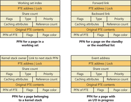
Although PFN database entries are of fixed length, they can be in several different states, depending on the state of the page. Thus, individual fields have different meanings depending on the state. Figure 10-42 shows the formats of PFN entries for different states.
Several fields are the same for several PFN types, but others are specific to a given type of PFN. The following fields appear in more than one PFN type:
PTE address Virtual address of the PTE that points to this page. Also, since PTE addresses will always be aligned on a 4-byte boundary (8 bytes on 64-bit systems), the two low-order bits are used as a locking mechanism to serialize access to the PFN entry.
Reference count The number of references to this page. The reference count is incremented when a page is first added to a working set and/or when the page is locked in memory for I/O (for example, by a device driver). The reference count is decremented when the share count becomes 0 or when pages are unlocked from memory. When the share count becomes 0, the page is no longer owned by a working set. Then, if the reference count is also zero, the PFN database entry that describes the page is updated to add the page to the free, standby, or modified list.
Type The type of page represented by this PFN. (Types include active/valid, standby, modified, modified-no-write, free, zeroed, bad, and transition.)
Flags The information contained in the flags field is shown in Table 10-17.
Priority The priority associated with this PFN, which will determine on which standby list it will be placed.
Original PTE contents All PFN database entries contain the original contents of the PTE that pointed to the page (which could be a prototype PTE). Saving the contents of the PTE allows it to be restored when the physical page is no longer resident. PFN entries for AWE allocations are exceptions; they store the AWE reference count in this field instead.
PFN of PTE Physical page number of the page table page containing the PTE that points to this page.
Color Besides being linked together on a list, PFN database entries use an additional field to link physical pages by “color,” which is the page’s NUMA node number.
Flags A second flags field is used to encode additional information on the PTE. These flags are described in Table 10-18.
Table 10-17. Flags Within PFN Database Entries
Table 10-18. Secondary Flags Within PFN Database Entries
Flag | Meaning |
|---|---|
The code signature for this PFN (contained in the cryptographic signature catalog for the image being backed by this PFN) has been verified. | |
AWE allocation | This PFN backs an AWE allocation. |
Prototype PTE | Indicates that the PTE referenced by the PFN entry is a prototype PTE. (For example, this page is shareable.) |
The remaining fields are specific to the type of PFN. For example, the first PFN in Figure 10-42 represents a page that is active and part of a working set. The share count field represents the number of PTEs that refer to this page. (Pages marked read-only, copy-on-write, or shared read/write can be shared by multiple processes.) For page table pages, this field is the number of valid and transition PTEs in the page table. As long as the share count is greater than 0, the page isn’t eligible for removal from memory.
The working set index field is an index into the process working set list (or the system or session working set list, or zero if not in any working set) where the virtual address that maps this physical page resides. If the page is a private page, the working set index field refers directly to the entry in the working set list because the page is mapped only at a single virtual address. In the case of a shared page, the working set index is a hint that is guaranteed to be correct only for the first process that made the page valid. (Other processes will try to use the same index where possible.) The process that initially sets this field is guaranteed to refer to the proper index and doesn’t need to add a working set list hash entry referenced by the virtual address into its working set hash tree. This guarantee reduces the size of the working set hash tree and makes searches faster for these particular direct entries.
The second PFN in Figure 10-42 is for a page on either the standby or the modified list. In this case, the forward and backward link fields link the elements of the list together within the list. This linking allows pages to be easily manipulated to satisfy page faults. When a page is on one of the lists, the share count is by definition 0 (because no working set is using the page) and therefore can be overlaid with the backward link. The reference count is also 0 if the page is on one of the lists. If it is nonzero (because an I/O could be in progress for this page—for example, when the page is being written to disk), it is first removed from the list.
The third PFN in Figure 10-42 is for a page that belongs to a kernel stack. As mentioned earlier, kernel stacks in Windows are dynamically allocated, expanded, and freed whenever a callback to user mode is performed and/or returns, or when a driver performs a callback and requests stack expansion. For these PFNs, the memory manager must keep track of the thread actually associated with the kernel stack, or if it is free it keeps a link to the next free look-aside stack.
The fourth PFN in Figure 10-42 is for a page that has an I/O in progress (for example, a page read). While the I/O is in progress, the first field points to an event object that will be signaled when the I/O completes. If an in-page error occurs, this field contains the Windows error status code representing the I/O error. This PFN type is used to resolve collided page faults.
In addition to the PFN database, the system variables in Table 10-19 describe the overall state of physical memory.
Table 10-19. System Variables That Describe Physical Memory