Chapter 10
Cisco DNA Infrastructure—Virtualization
The previous chapters focused on the hardware and software innovations that Cisco DNA offers: the flexibility of introducing new protocol and feature innovations into the Unified Access Data Plane (UADP) or the QuantumFlow Processor (QFP) as new technologies emerge, and the functional and operational consistency that Cisco IOS XE provides across all parts of the architecture, including switching and routing. This chapter adds another tool to the Cisco DNA toolbox—virtualization. It focuses on the virtualization of those functions that manipulate and forward packets—that is, on Cisco Network Function Virtualization (NFV)—instead of virtualizing application workloads. This chapter also discusses transport virtualization, the segmentation of the transport network to offer virtual networks.
Network Function Virtualization allows you to run network functions inside virtual machines on standard Intel x86–based hosting platforms. Many of the tenets of Cisco DNA outlined in Chapter 5, “The Cisco Digital Network Architecture Blueprint,” are supported by virtualization. NFV is inherently software driven. These functions are typically much easier to deploy, especially when combined with programmability. A virtualized network function (VNF) is spun up within minutes, triggered by a REST, RESTCONF, or NETCONF call. This also allows you to extend the network services in Cisco DNA easily. Many of the VNFs under consideration provide additional security functionality, supporting the tenet of security in Cisco DNA. Furthermore, the virtualization architecture in Cisco DNA is fully open, offering application programming interfaces (APIs) at all software layers to partners or customers, and even allowing the instantiation of third-party VNFs to give you even more deployment flexibility. NFV is thus a prime example of how Cisco DNA changes the architecture to align the network with your business intent.
Transport virtualization has been a standard tool in building enterprise networks for many years now. User traffic is segmented from each other by means of virtual LANs (VLANs), Virtual Extensible LAN (VXLAN), or virtual routing and forwarding (VRF) instances. More recently, concepts like Cisco TrustSec Security Group Tagging (SGT) gained popularity as enhanced policy-based mechanisms for segmentation.
This chapter explains the following:
Benefits of virtualizing network functions
Use cases for virtualization
The building blocks of a virtualized system architecture
Challenges and deployment considerations
Transport virtualization
The chapter begins by reviewing some of the benefits that virtualization offers, organizing these around architectural, operational expenditure (OPEX), and capital expenditure (CAPEX) benefits. The following section then describes the use cases that emerge in the enterprise today: virtualizing control plane functions, simplifying branch architectures with virtualization, virtualizing the connectivity to multiple cloud environments, and virtualizing network functions in the cloud. The subsequent section then delves into the overall system architecture of an x86-based host running multiple VNFs. Particular attention is given here to the various input/output (I/O) mechanisms that are available to share physical interfaces among multiple VNFs, since this is often a bottleneck in the overall architecture. This chapter then elaborates on the dominant challenges that Network Function Virtualization introduces, such as understanding the attainable performance when running multiple VNFs side by side, or deciding the granularity with which VNFs should be deployed from a multitenancy and multifeature perspective. The latter part of this chapter then reviews transport virtualization in detail, highlighting different methods for segmentation of the data plane (e.g., TrustSec, VLANs, VxLANs, VRFs) as well as the control plane segmentation.
Benefits of Network Function Virtualization
Virtualization of application workloads has been extremely successful for IT departments over the past decade. Prior to application virtualization, many servers were dedicated to host a small number of applications, the servers often running at single-digit utilization levels and thus incurring a lot of costs. Application workload virtualization proved that a common x86-based hosting platform can be shared to use the underlying host hardware resources more efficiently. This proof point inspired the idea of virtualizing network functions to reap similar cost benefits. In addition to total cost of ownership (TCO) benefits related to OPEX and CAPEX, NFV can also be leveraged to change the overall network architecture.
The following sections discuss the CAPEX, OPEX, and architectural benefits of NFV in detail
CAPEX Benefits of NFV
NFV promises to reduce capital expenditures by deploying standard Intel x86–based servers instead of dedicated hardware appliances. In an appliance-based model, specialized networking appliances are deployed to deliver networking functions, in particular so-called Layer 4—Layer 7 functions (WAN optimization, intrusion detection and prevention, network or port address translation, etc.). Such appliances are often more expensive than x86-based server platforms. Furthermore, a standard x86-based server can host multiple virtualized network functions, allowing for the same hardware architecture to be used for multiple purposes. This promises to deliver CAPEX benefits on two fronts:
Economies of scale: Leveraging the same hardware platform for multiple functions may allow for larger-volume discounts from server vendors. This is especially the case if the same server platform used in your data centers for application workload hosting is leveraged.
Reduction in hardware purchases: Consolidation of multiple virtualized network functions into the same hosting platform can reduce the total number of hardware devices that need to be acquired and operated.
Table 10-1 outlines the CAPEX benefits of NFV.
Table 10-1 CAPEX Benefits of Network Function Virtualization
CAPEX Benefit of NFV |
Description |
Deployment of standard x86-based servers |
Servers considered cheaper than routers/appliances. Servers already deployed in branch, data center (DC), or points of presence (PoP). |
Deployment of best-of-breed services |
Separation of network functions allows best-of-breed (virtualized) services. Eliminates vendor lock-in. Encourages openness and competition among software vendors. CAPEX reduction through competition. |
Cost reduction through economies of scale |
Deployment of huge server farms in DCs leads to better resource utilization. |
Simplified performance upgrades |
Capability to increase performance without forklift upgrades. |
These benefits should also be examined critically on a case-by-case basis. For example, comparing only the cost of the hardware portion of an Intel x86–based platform (without the associated software functionality) to an appliance priced for both hardware and software can be misleading. Intel x86–based hosts may have shorter depreciation cycles as purpose-built appliances and may require more frequent upgrades. Although the CAPEX for an x86-based host may be cheaper, replacement costs may be incurred more frequently. It is thus important in a TCO comparison between an appliance-based architecture and a virtualized architecture to apply the same timeframe for the comparison, and include all aspects of the costs—software and hardware—needed to deliver the functionality.
OPEX Benefits of NFV
From an OPEX point of view, NFV also promises cost reductions. Consolidating multiple network functions from dedicated appliances into a single server platform promises to simplify hardware management. Gone are the days when the hardware architecture for each network function had to be fully understood to be managed. In a virtualized world, functions run on standard x86-based server platforms—and the latter are typically very well understood from a management perspective.
Specifically, this triggers OPEX savings on multiple fronts. Hardware element management is now common regardless of which virtualized network function is instantiated on top of it. Furthermore, in highly distributed network environments (think thousands of branches), such a reduction in the hardware platforms can also pull through additional OPEX savings, for example, by reducing site visits. Multiple hardware-based appliances in the branch increases the likelihood of one failing. Today, such a failure often requires specialists to visit the site for replacement. Collapsing multiple network functions into a single host reduces such failure occurrences, and thus the need for onsite support.
Using the same type of hardware in the data center for application workload hosting and in the network for NFV also promises additional OPEX savings. Synergies can be achieved by combining the workforce to look after the x86-based servers—regardless of whether these are hosting application workloads or VNFs. In the long run, organizational efficiencies are even achieved by merging L4–L7 network function operations teams with the application hosting teams.
From a flexibility perspective, NFV also simplifies the deployment of a function and thus further reduces OPEX. In an appliance-based model, deployment of a new network function typically implies acquisition of the hardware, testing, staging, shipment, etc. Since NFV is based on software running on standard x86-based servers, the deployment of a new function is typically simpler. Spare x86 CPU, memory, and storage resources may already be deployed, eliminating the need to test and stage new hardware. The deployment of a new function may thus reduce to testing the software aspects of the new function. And, of course, this benefit extends to future software upgrades as well. Gone are the days of hardware end-of-life announcements triggering a cycle of replacement hardware selection, testing, staging, shipment, and deployment. If an x86-based host becomes obsolete, a new server (with the same architecture) is easily deployed.
Table 10-2 outlines the OPEX benefits of NFV.
Table 10-2 OPEX Benefits of Network Function Virtualization
OPEX Benefit of NFV |
Description |
Reduction of branch visits |
Changes/upgrades in the service can be made in software. No longer need to swap appliances onsite for service upgrades or appliance failures. |
Automated network operations |
Virtualization places focus on automation and elasticity, particularly for the initial deployment of a network function. |
Flexible VNF-based operation |
Software upgrades are done independently per VNF. VNFs are placed flexibly in branch, DC, or PoPs. |
Elimination or reduction of organizational boundaries |
IT and network operations align. |
Architectural Benefits of NFV
In addition to CAPEX and OPEX savings, NFV also offers potential architectural simplifications. Take for example direct Internet access in branches. A common Internet access architecture is to backhaul all traffic destined outside of the enterprise to a centralized or regional data center. Connectivity to the untrusted Internet is protected by a demilitarized zone (DMZ) in those locations, where firewalls, intrusion detection and prevention (IDS/IPS), or similar security functions are deployed. With NFV, such functions may be deployed in the branches themselves, offering a direct breakout to the Internet instead of backhauling to a DMZ. Such an architectural change offers reduction of WAN bandwidth. The increased scale in managing hundreds or possibly thousands of security VNFs in this model is addressed by automation. In the distributed VNF model, the configuration and management of VNFs is highly automated and programmable, deploying identical security policies in each branch and thus addressing the concern of network operators of running highly distributed environments.
Another example for a potential architecture shift enabled by NFV revolves around high availability (HA). Many current high-availability architectures are designed to recover from failures within 50ms (a timeframe that originated from voice and SONET/SDH requirements). The designs typically embrace full redundancy at many layers. Redundant hardware complemented by software redundancy protects against respective hardware and software failures. Aggressive liveliness protocols such as Bidirectional Forwarding Detection (BFD) are deployed to detect failures within milliseconds. For stateful functionality like network address translation (NAT) or firewalls, session state redundancy is deployed to duplicate the state databases in redundant systems. In an architecture with VNFs, some network operators may choose to simplify network redundancy by deploying standby VNFs, which may be spun up only (cold standby), or even preconfigured (hot standby) on redundant servers. For applications that tolerate a failover time longer than 50ms, such alternative HA architectures may be acceptable and lead to further TCO savings.
Yet another example of an architectural option revolves around capacity expansion. In a hardware appliance–based architecture, additional capacity requirements trigger the deployment of extra hardware, or a replacement of the lower performing appliance by a higher performing model. In a virtualized architecture, additional capacity is deployed by either instantiating a VNF with more associated CPUs or by horizontally scaling additional VNFs next to the existing VNF. Again, this simplifies the overall network architecture and brings about cost savings. Table 10-3 summarizes the architectural benefits of NFV.
Table 10-3 Architecture Benefits of Network Function Virtualization
Architecture Benefit of NFV |
Description |
Reduction of the number of network elements to manage and deploy |
Integration of network functions into a single system. reduces the number of appliances/network elements (NE) to manage and configure. Fewer hardware types to deploy and plan for. |
Service elasticity |
Deployment of VMs much faster than appliances. Easy scale up and scale down of services. Flexible service portfolio (mixing VNFs). |
Operational efficiencies through virtualization |
Leverages virtualization advantages from data center (vMotion, dynamic resource scheduling, power management, etc.) also for VNFs. |
Reduced complexity for high availability |
Virtual machines (VM) have a smaller failure domain. Stateless deployments become more acceptable, so less complexity through stateful redundancy deployments. In-service Software Upgrade (ISSU) simplified by deploying a NEW VM and failing over. |
Not all of the examples listed so far may apply to your environment. Enterprise networks are highly diverse and often particular to each organization. But the point is simple: with NFV, you as an operator have another tool available to design and run your enterprise network. If you find the cost of embracing and adopting NFV acceptable, add this tool to your toolbox and benefit from the advantages described in this section.
Use Cases for Network Function Virtualization
Let’s now take a look at the imminent use cases for NFV that emerged in the enterprise market. In general, these use cases are categorized into four main buckets:
Virtualization of control plane functions
Deploying VNFs in a virtual private cloud (VPC) for reachability
Virtualizing branch transport and Layer 4–7 functions
Leveraging virtualization to connect to public clouds
Control Plane Virtualization
The first use case for NFV centers on control plane functions. Today, all networks require such functions to exchange state information to achieve a successful transport path from the source to the destination of IP flows. Three examples of such control plane functions are as follows:
Route reflectors (RR): Route reflectors are often already implemented as an appliance, learning prefixes and forwarding information from, for example, Border Gateway Protocol (BGP) neighbors and distributing the relevant forwarding information back to such neighbors. In large networks, deployment of such control plane appliances increases the scalability by avoiding a full mesh of neighbor sessions.
LISP Map-servers/Map-resolvers: Map-servers and -resolvers in the Locator/ID Separation Protocol (LISP) perform the function of storing information about endpoints in a distributed database. The Map-Server/Map-Resolver (MS/MR) accepts prefixes identifying endpoints in the network and responds to queries from LISP Egress and Ingress Tunnel Routers (xTR) seeking information about an endpoint.
Wireless LAN controllers (WLC): WLCs are responsible in the network to manage the operations and behavior of the access points under their governance. Examples of functions performed by a WLC include authentication of clients and access point configuration (e.g., for radio resource management). Deployment of a virtualized WLC becomes particularly effective when wireless traffic is not tunneled back to the WLC; that is, when the WLC operates the wireless control plane only.
Of course, there are many more such examples. In various network appliances, such functions already run on x86 CPUs. Take for example the Cisco Aggregation Services Router (ASR) 1000 Series routers. In an ASR 1000, a powerful processor—QFP—delivers the data plane forwarding performance. Packets forwarded between interfaces are sent to this processor and treated there by applying the relevant forwarding plane features (including NAT, firewall, routing, etc.), and are then sent on toward the destination IP address on an egress interface. Control plane packets, however, are processed by the x86 CPU that also is part of the overall ASR 1000 system architecture. Routing protocols (BGP, Open Shortest Path First [OSPF], Enhanced Interior Gateway Routing Protocol [EIGRP]), and multicast control plane functions are all examples of processes that are executed in the onboard x86 CPU of an ASR 1000. Control plane packets do not benefit from the hardware acceleration offered by QFP.
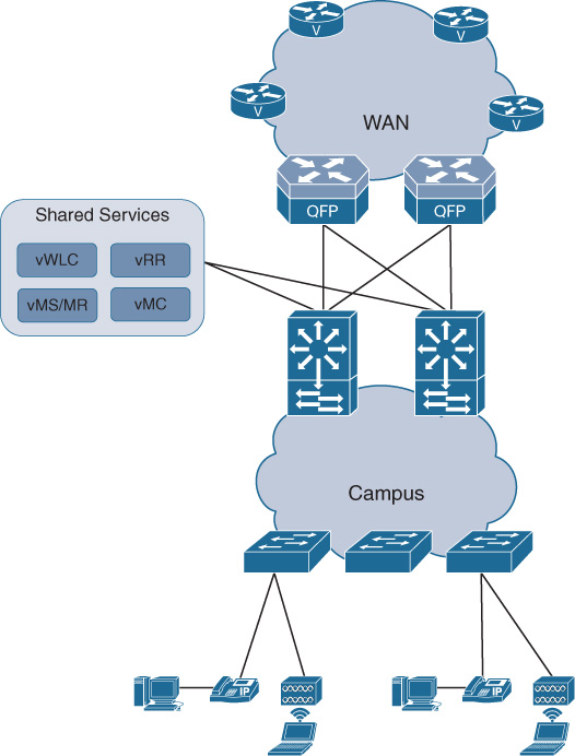
Any control plane software processes that leverage x86 compute resources are thus prime candidates to virtualize in an NFV-enabled architecture. VNFs like the Cisco CSR 1000v are already deployed as virtualized BGP route reflectors. The Cisco Virtual Wireless LAN Controller (vWLC), or a Performance Routing virtualized Master Controller (vMC) are other examples of where control plane functionality is deployed as a VNF. And in many cases, the attainable performance in such a virtualized environment can be at par with the performance of the appliance-based deployments. Figure 10-1 illustrates the architecture of placing virtual control plane functions in a shared services area in a campus network.
Branch Virtualization
The second use-case category for NFV is targeting branch environments. In many branches, multiple appliances are deployed. Routers provide connectivity to the rest of the enterprise network, possibly using a service provider’s virtual private network (VPN) or Internet service. WAN optimization appliances may be installed to optimize the traffic over the WAN. WLC appliances may be deployed in larger branches to configure access points. Voice or security appliances are often also part of the branch architecture. Throw in a switch for connectivity! It is thus not uncommon to have numerous dedicated appliances in branches. And redundancy is often a requirement, so the number of deployed systems can immediately double.
All of these hardware systems must be maintained, operated, and managed. New software functionality or patches may be required. Hardware failures may occur, triggering an onsite visit by a skilled engineer. Vendors may run out of parts for a system and be forced to announce the end of sale, and ultimately support, for one of the deployed systems. Such events trigger network-wide fleet upgrades of the deployed system. None of this may contribute significantly to the TCO if these costs are incurred a single time. But many organizations are operating enterprise networks with hundreds or even thousands of branches, typically spread over a wide geographic area. Any single operation, any cost incurred for a single branch, is thus immediately multiplied by the number of branches in the organization’s network.
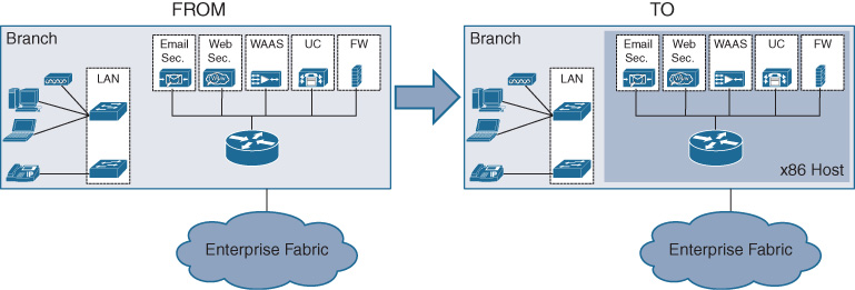
The virtualization of network functions promises to make a significant impact on the TCO in such an environment. Imagine that your branches consist of an x86-based server (or two for redundancy) where routing, WAN optimization, WLC, and other functions are collapsed into a single chassis. This significantly simplifies the hardware landscape of the branch. When coupled with automation enabled by increasing programmability of the VNFs, and multiplied by the number of branches in your network, significant TCO savings is achieved. This is what makes the branch virtualization use case so attractive for many enterprise network architects! Figure 10-2 shows the concept of collapsing multiple appliance-based functions into an x86-based host and running the functions as virtual machines.
Virtualization to Connect Applications in VPCs
The third use case that is also already widely deployed centers on connectivity to applications running in virtual private cloud environments. Many of you are embracing services by Amazon, Microsoft, Google, or the like to host enterprise applications in a virtual private cloud (VPC) environment. The benefits of a VPC are by now well apparent for many enterprises: you can deploy an application without lengthy and costly investments in server infrastructures. You consume the infrastructure—servers and their OS—as a service. You don’t have to worry about backups or server failures. The list goes on. But how to get your traffic to such a VPC environment? By now the answer should be obvious: run virtualized network functions in the VPC.
Figure 10-3 illustrates this use case. A virtual router such as the Cisco CSR 1000v is deployed inside the VPC as a VNF, and configured to provide connectivity to the rest of your enterprise network. Of particular importance are encrypted tunnels and WAN optimization functionality. By connecting the virtual router in the VPC with your enterprise network environment, the VPC effectively becomes a natural part of your overall architecture—just like a branch that is connected over an untrusted provider. The same security functionality, the same WAN optimization functionality, and the same firewall or IPS/IDS functionality are applied in the VPC as in your branch architectures—albeit deployed as virtual machines.

For many cloud providers, offering such VNFs becomes part of the service catalog. The VNFs are ordered from the marketplace and instantiated in an automated way. APIs into the cloud providers allow you to program the behavior of these VNFs. In most cases, the consumption model of such networking VMs is aligned with the overall VPC consumption model, for example by offering term-based licenses.
Virtualization of Multicloud Exchanges
The move of applications into cloud environments also motivates the fourth use case that is currently considered by many enterprises: virtualizing the DMZ. In many cases, the discussion about hosting applications in the cloud has already progressed beyond a single VPC architecture. Applications hosting is being designed for hybrid and multicloud environments. They can be hosted by multiple VPC providers and be migrated from one environment to the other, including back into an enterprise-operated cloud. Applications are also increasingly being consumed as a service over Internet connections.
As a result, the traditional security perimeter that motivated traditional DMZ architectures is changing significantly. The security perimeter in a cloud-first architecture is required to cover all of the above application hosting environments. These are also likely to be much more distributed in the enterprise architecture than traditionally centralized DMZs.
And this is where virtualization comes in! NFV helps in this use case to build security perimeters that are customized based on the type of external connectivity. For applications hosted as a service, you can choose to deploy one type of a chain of VNFs. For applications hosted in a VPC, another type of VNF chain can be instantiated. All other external connectivity—for example, to the Internet or extranet partners—also receives a customized network treatment by instantiating the appropriate and relevant VNFs.
This use case is illustrated in Figure 10-4. VNF service chains can be deployed depending on where the traffic comes from and where it is going. In today’s use cases, the VNFs focus on applying the appropriate security functionality (e.g., firewalls, IPS/IDS, web filtering, etc.), but other VNFs can, of course, also be chained in. NFV enables this use case by allowing such deployments to be flexible, granular, on-demand, and automated. In many cases, the functional components of such an virtualized security perimeter are hosted in carrier-neutral facilities. The resulting architecture therefore is typically described as a cloud exchange, rather than an evolved DMZ. The idea may have started with “let’s virtualize DMZ functions” but has evolved to much more by combining virtualization, carrier-neutral facilities, automation, and virtualized service chains that are instantiated on a per-source-destination-pair basis.

The mentioned use-cases are examples of where virtualization already plays a role in many network architectures. They are also great examples of how virtualization is not simply a replacement of an appliance chassis with an x86-based host. The use cases emerged because they address a particular problem or are offering architectural benefits that could not be addressed in the same way with a hardware-based appliance. The key learning from these use cases is: virtualization is a great additional tool in your toolbox, but it does not replace hardware based systems!
Overview of an NFV System Architecture
Now that we have explored the business benefits of NFV and examples of compelling use cases, let’s dig into the solution architecture in this section. The four main components of a virtualized system architecture are as follows:
An x86-based hosting platform offering the hardware resources (CPU, memory, storage, interfaces, etc.)
The x86-based operating system with virtualization support (e.g., KVM)
One or more virtualized network functions; the software processes that treat the IP flows, perform forwarding decisions, and apply networking features as configured
The automation and programmability platform.
In a basic virtualized system architecture, hardware resources (CPU, memory, and storage) based on standard server technologies such as Intel x86 processors are being abstracted by a hypervisor layer to present virtual CPU/memory/storage to virtual machines or applications that run on top of the hypervisor. The focus of NFV is to run networking functions inside a virtual machine, as opposed to running VNFs in a container or running applications directly on the host OS.
Figure 10-5 shows the main differences between a type 1 hypervisor, a type 2 hypervisor, and Linux containers. Type 1 hypervisor operating systems directly control the hardware and offer a virtualization environment to present virtual compute resources (memory, storage, CPU, I/O, etc.) to one or more virtual machines. An example of a type 1 hypervisor is VMware ESXI.
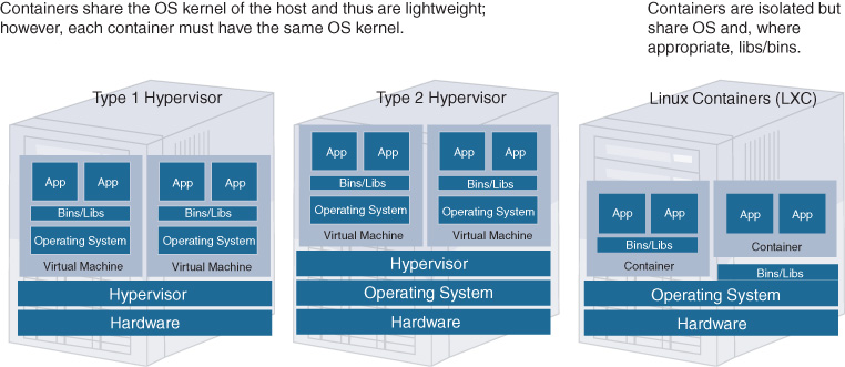
In a type 2 hypervisor, a standard operating system such as Linux controls the server hardware, and the hypervisor runs on top of the host OS to perform hardware abstraction toward the virtual machines. An example of a type 2 hypervisor is Kernel-based Virtual Machine (KVM) for Linux.
In both cases, an additional operating system is running inside the virtual machines to accommodate the application workloads. In some cases, this additional VM OS may be beneficial; for example, if the application is supported on an OS that differs from the underlying hardware OS. Applications with different OS support can thus run on the same host.
Linux containers run applications in segregated environments on top of the host operating system kernel directly. No additional OS inside the container is required. The segregation consists of separating the name spaces, isolating the operating environment of the containerized applications. Resources can also be isolated between containerized applications and the kernel, and can also be prioritized (c.f. Linux cgroups). Libraries are shared where appropriate.
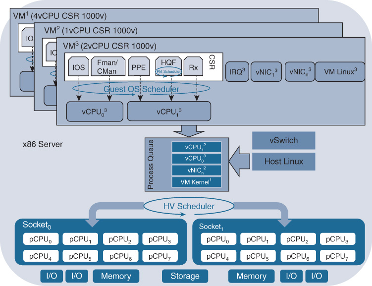
For networking VNFs, one or more software processes are running inside the VM to perform packet processing (e.g., firewall, routing, IPS/IDS, etc.). These software processes are associated with the virtualized CPUs allocated to the VM, and this association is either static or floating and depends on the software architecture of the VNF. For example, for the Cisco CSR 1000v virtual router, the Cisco IOS XE networking software runs multiple processes (representing data plane, control plane, and middleware communication functions) that are now executed inside a VM. These IOS XE software processes are statically mapped to virtual CPUs (vCPU) within the virtual machine. Some of the VNF internal software processes have strict timing requirements to ensure a successful operation. Processes can be monitored by watchdog timers to verify their liveliness.
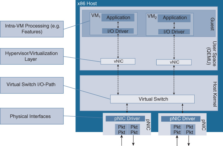
In addition to the vCPU threads configured for a VM, numerous VM system threads are also generating processing loads. Examples are the VM kernel process, virtual network interface card (vNIC) processes, or interrupt processes. The aggregate of all vCPU processes from the set of VMs as well as the VM-specific processes are presented to the hypervisor layer for scheduling onto physical CPU cores. Additional software processes, such as those for virtual switching in the operating system, may also request CPU resources. The hypervisor scheduler is responsible for allocating all these processes in its process queue to the physical CPUs for a time slice, as well as to manage memory or storage access. A simplified representation of a virtualized system architecture focusing on the CPU resources (both physical and virtual) is depicted in Figure 10-6.
A virtualized system architecture may expose various throughput bottlenecks, as shown in Figure 10-7. For example, the physical port density and speed of the server may constrain the amount of traffic that is processed. The set of networking VMs running on the server may be capable of processing more traffic than the servers’ physical ports. Another bottleneck may be the hypervisor scheduler, in particular if a large number of processes need to be allocated CPU cycles with strict timing. The VNF typically has a maximum packet processing capacity that may also limit its throughput. Perhaps the most important bottleneck to understand in I/O-bound networking environments is the packet path from the physical NIC (pNIC) into the VMs. A variety of technology options exist to pass packets from a physical interface into a virtual machine: in KVM, Open vSwitch (OVS), with or without Intel’s Data Plane Development Kit (DPDK) support, is available. An open source virtual switch project called Fast data – Input/Output (FD.io) is another alternative. Virtual machines are even bound more tightly to a physical interface, for example, by configuring a direct Peripheral Component Interconnect (PCI) pass-through mode, or by deploying single-root I/O virtualization (SR-IOV). These different techniques are explained in more detail later in the chapter.
Hypervisor Scheduling and NUMA
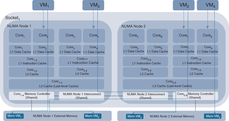
The hypervisor scheduler can implement fairness to regulate the processing of the workloads. For example, KVM implements a standard Linux Completely Fair Scheduler (CFS) that time-slices between processes, supporting dynamic process priorities and pre-emption. VMware’s ESXi scheduler typically allocates equal shares to each vCPU, but allows vCPU processes to have scheduling entitlements. Related vCPU processes can also be co-scheduled to avoid synchronization latencies. To optimize the utilization levels of the individual cores or to improve the power efficiency of a socket, the scheduler may move processing threads from one physical CPU to another. The processing thread is moved either in the same CPU socket or in another socket. This results in thrashing the instruction and data caches (that is, resulting in CPU caches that may need to be repopulated). Such scheduling activities can thus impact the processing of the software workloads, and even lead to sporadic packet losses. Translating the virtual memory addresses used by a VM into the underlying physical memory addresses is another important function performed by the hypervisor.
It is important to note that the hypervisor scheduler has no awareness of the VM internal software processes or its software architecture. The VM abstracts its internals toward the hypervisor via the vCPU and vNIC processes. In a networking environment this implies that the hypervisor scheduler, for example, has no awareness of a packet queuing process that needs to be executed, or if a VM internal watchdog timer process requires CPU cycles. For example, the Egress Quality of Service (QoS) scheduler within the virtual machine governs the order in which packets are egressed out of the virtual machine. It allows for low-latency voice packets to gain preferential treatment over best-effort packets. The system’s hypervisor scheduler, however, is not aware of or even synchronized with the actions of the VM internal QoS scheduler, as depicted as HQF in Figure 10-6.
Figure 10-8 reveals further details of a single-socket multicore architecture. Non-uniform Memory Access (NUMA) architectures enhance the performance in a multicore architecture by providing separate memory for each processor core and thus enabling these cores to hit their respective memory banks in parallel.1 An x86-based server is typically equipped with two sockets, each providing multiple CPU cores. A hierarchical layer of caches accompanies the cores. Each core has its own L1 cache with very fast memory access. A pair of cores shares the L2 cache, which is bigger in size. The third layer in the cache hierarchy is the L3 cache, which is shared among all cores on a socket. The scheduling algorithm of the hypervisor determines which software process (e.g., vCPU) gets scheduled onto which core. NUMA also provides a bus to allow data to move between the different memory banks and to access data residing in memory associated with other cores. Ensuring that related software processes are scheduled onto the same socket and, ideally, close onto cores sharing the same L1/L2 caches may positively impact performance. If related processes are scheduled onto cores sharing the same L1/L2 cache, the memory state (e.g., packet buffer) does not need to be repopulated. On the other hand, if related processes requiring the same memory state are scheduled onto cores that only share the L2 cache or are even scheduled onto different sockets, memory state needs to change, leading to cache trashing that can impact the overall performance of the software processes. NUMA also provides a QuickPath Interconnect (QPI) bus to allow data to move between the different memory banks and to access data residing in memory associated with other cores. Memory access bandwidth across this QPI link is slower than accessing memory on the same socket.
1 M. Falkner, A. Leivadeas, I. Lambadaris, G. Kesidis, “Performance Analysis of virtualized network functions on virtualized systems architectures,” IEEE 21st International Workshop on Computer Aided Modelling and Design of Communication Links and Networks (CAMAD), 2016: 71–76.
Note that the Cisco Enterprise Network Compute System (ENCS) and the Cisco Cloud Services Platform CSP2100 offer some of these optimizations out of the box. For example, vCPUs assigned to VNFs are typically pinned to particular physical CPUs. Similarly, memory management is configured in the Cisco Enterprise Network Function Virtualization Infrastructure Software (NFVIS) to be optimized for the VNFs.
Input/Output Technologies for Virtualization
Virtualization of network functions differs from application virtualization. In the former case, the I/O workload generated by packet flows dominates. By definition of a VNF and its purpose being to process networking traffic, packets are continuously arriving into the server and need to be passed to its respective VM for processing. Networking VMs are thus generating high I/O workloads for the hypervisor and, as such, are referred to as I/O bound. Other VNFs may also be storage or memory bound, especially for L4–7 networking operations where the entire payload of a packet needs to be processed. In contrast, many non-networking applications receive only a limited number of external inputs. Their requirement for CPU cycles is predominantly for algorithmic computations, possibly also with intensive memory and storage access. Such applications or networking functions consequently become compute bound. Understanding the resource demands from either VNFs or applications mixed on a particular general-purpose server is important to maximize its utilization.
In general, packets arrive on the physical NIC and are copied into memory via two direct memory access (DMA) operations. Along with the packet copy, a descriptor specifying the buffer location (memory address and length) is also copied into memory. The pNIC then sends an interrupt to indicate the arrival of the packet, as shown in Figure 10-9.
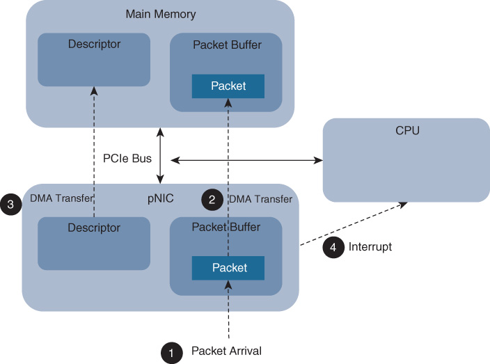
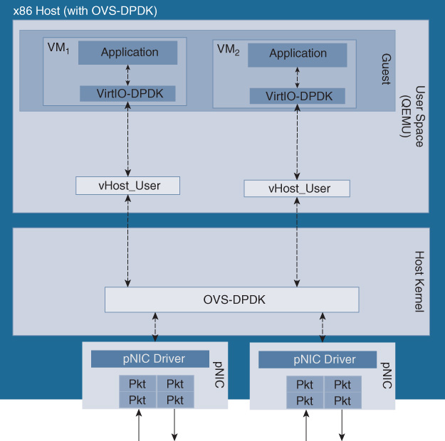
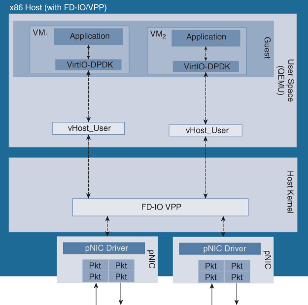
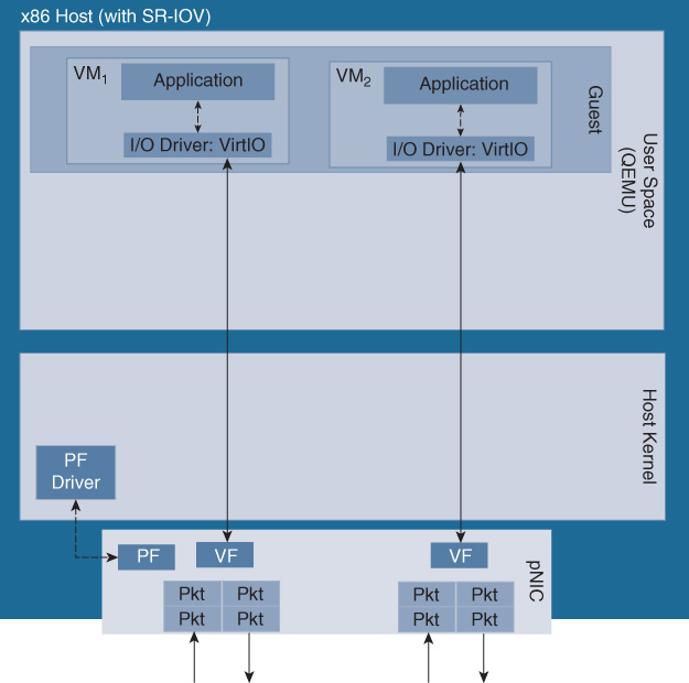
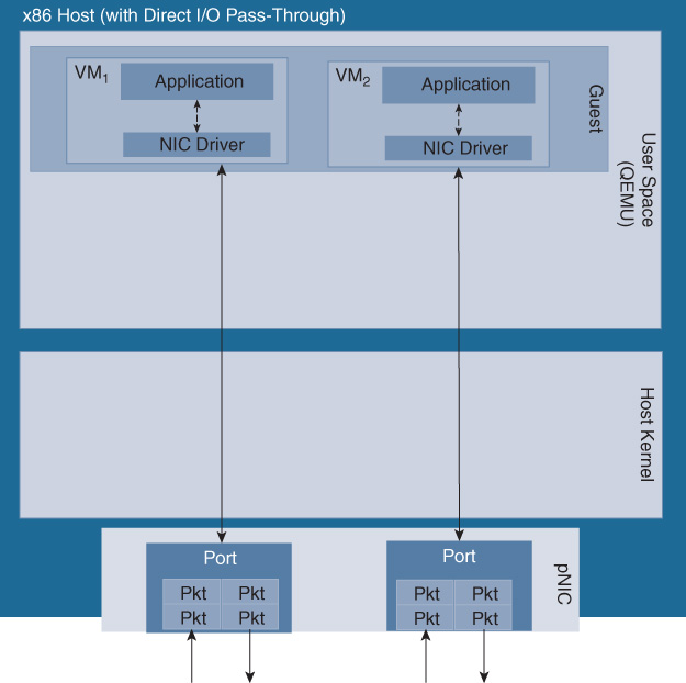
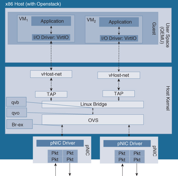
The size of the packet buffers, the descriptors, as well as the number of interrupts are further examples of bottlenecks that may ultimately impact the throughput. The packet is then processed by the virtual switch or a Linux bridge process such as OVS, OVS-DPDK, FD.io VPP, SR-IOV, direct PCIe pass-through, or an OpenStack I/O path. The different system configurations are illustrated, respectively, in Figures 10-10 through Figure 10-15.
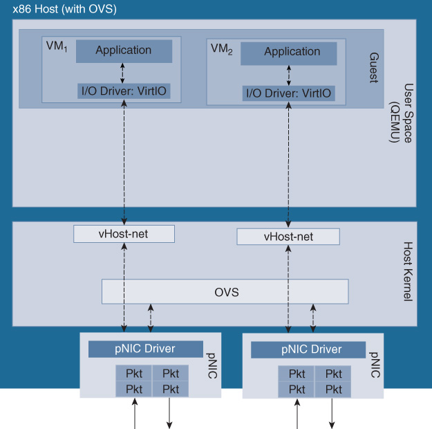
In the case of OVS-DPDK, packets are passed to the virtual switch for distribution to the destination VNFs (Cisco CSR 1000V instances), assisted by the DPDK libraries for fast packet processing. The DPDK libraries offer a poll mode driver (PMD) that allows packets to pass from the physical interface to the virtual switch (user space) directly, thus avoiding the networking stack of the kernel. OVS-DPDK offers enhanced switching functionality, supporting, among others, jumbo frames, link bonding, native tunneling support for VXLAN, Generic Route Encapsulation (GRE) or Generic Network Virtualization Encapsulation (GENEVE), Multiprotocol Label Switching (MPLS), or ingress/egress policing. From a CPU resource perspective, OVS-DPDK is relying on CPU cycles from the host’s x86 core to switch packets, thus stressing the hypervisor scheduler in a system where multiple VNFs are also contending for the same CPU cycles. Any CPU core associated for switching to OVS-DPDK becomes unavailable to process VNFs. OVS-DPDK can, however, be configured to use multiple CPU cores for packet switching to increase its throughput toward the VNFs. Note that Figure 10-10 and Figure 10-11 highlight the pertinent queues in these setups. Such internal queues are set up to pass packets on their path from the virtual switch into the VNFs, and their depths can become a bottleneck with high data rates. For OVS-DPDK the pertinent queues are in the DPDK driver in the guest user space.
FD.io VPP (vector pocket processing) is an open source alternative solution to optimize the I/O path in a virtualized system.2 Running as a Linux user-space process, the FD.io VPP drivers enable NIC access over PCI. FD.io processes multiple packets with similar characteristics (called vectors). Packets are removed from the receive rings of the interface and are formed into a packet vector, to which a processing graph is then applied. The processing graph represents the features that need to be applied (e.g., IPv4 forwarding, classification, multicast, etc.). This approach minimizes interrupts and traversing a call stack and thus also thrashing of the instruction caches and misses. VPP processes multiple packets at a time, making it a high-performance processing stack that supports even more networking functions than OVS-DPDK. Features such as Dynamic Host Configuration Protocol (DHCP), segment routing, Address Resolution Protocol (ARP), Layer 2 Transport Protocol version 3 (L2TPv3), VRFs, IPv6, and MPLS-over Ethernet are all supported. Similar to OVS-DPDK, FD.io VPP makes use of Intel’s DPDK library to accelerate packet processing, and thus requires CPU cycles to process packets which become unavailable for VNF processing. The number of CPU cores assigned to FD.io VPP can be configured. FD.io VPP also leverages internal queues in the DPDK driver in the guest user space to pass packets from the virtual switch into the VNFs. An FD.io-based virtualized system architecture is shown in Figure 10-12.
2 M. Konstantynowicz, “FD.io: How to Push Extreme Limits of Performance and Scale with Vector Packet Processing Technology,” https://www.ietf.org/proceedings/96/slides/slides-96-bmwg-10.pdf.
SR-IOV, in contrast, offers a virtualized Peripheral Component Interconnect Express (PCIe) pass-through mechanism that does not rely on the hypervisor to pass packets between the NIC to the individual VNFs. SR-IOV virtualizes PCIe, creating PCIe physical functions (PF) and virtual functions (VF). This allows a physical port to be shared among multiple VNFs. The processing of features in an SR-IOV setup is entirely done inside the VNF, requiring the VNF to support the appropriate drivers. Features such as VXLAN, MPLS, policing, etc. previously mentioned for OVS-DPDK and FD.io VPP now have to be applied to packets inside the VNFs. SR-IOV has some functional limitations due to its dependency on the underlying hardware and software. The server’s NIC cards and the BIOS have to support the technology. Further caveats are, for example, the number of VFs that can be configured for a physical NIC, currently limiting the number of VFs to 128 on an Intel Fortville NIC, but the practical limit can be as low as 64. Depending on the hardware and the driver implementation, other caveats may exist such as packet mirroring, VLAN filtering, multicast addresses, or promiscuous unicast.
After processing by the virtual switch, the packet is fetched by the vNIC to be handed off to the actual VM I/O driver (for example, Virtio). In case of SR-IOV, the packets are directly fetched by the SR-IOV driver inside the VM. Note that packets may thus be copied several times as they are passed from the virtual switch to the application, using a vNIC as well as the virtual machine’s I/O driver. Such packet copy operations place additional requests onto the hypervisor scheduler, and may limit the throughput and cause additional delay or even packet losses. All of the above I/O paths can thus also have throughput limitations.
Figures 10-13, 10-14, and 10-15 illustrate a virtual system architecture with SR-IOV, direct PCIe pass-through, and OpenStack, respectively.
Challenges and Deployment Considerations of Network Function Virtualization
As you can imagine, virtualizing network functions also has implications on how you deploy and operate your network. Consider performance. What are the performance characteristics of virtualized network functions as compared to physical appliances? Another aspect revolves around deployment models: how many VNFs should you deploy on an x86-based host, and should they be configured analogous to a physical appliance? These topics are the focus of the next section.
Performance
The previous section highlighted the major components of a virtualized system architecture: a hardware host based on a standard x86 architecture, with shared CPU, memory, storage, and I/O resources, and running a standard operating system (e.g., Linux in many cases) to schedule software processing requests and managing the system. Such a system architecture deviates significantly from specialized hardware appliances such as routers, switches, firewalls, etc. that were optimized for decades from both a hardware and software perspective.
Take for example a Cisco ASR 1000 Series router. Its forwarding plane is based on the QuantumFlow Processor, which is optimized to forward packets while applying a broad set of features. The I/O path in the ASR 1000 connects the physical interfaces to the QFP, and is wired to ensure no packet loss, allowing for priority lanes and XON-XOFF feedback loops to ensure that backpressure is applied and that the system behaves in a predicable manner. Sophisticated hardware assists ensure that encrypted traffic is handled with high performance, or that classification lookups (e.g., for ACLs or QoS) support the desired throughput rates.
Many of the optimizations that are embedded in dedicated networking appliances are missing in general-purpose x86-based hosts. Underlying hardware resources are shared typically between many VNFs and applications. Traffic destined to different VNFs or applications shares common physical interfaces. CPU cycles are pooled to serve all of the processes installed on the host. Memory and storage are also not dedicated to particular processes. And by virtue of deploying off-the-shelf x86-based hosts, any hardware optimizations that appliances offer for efficient transport and processing of network traffic are also absent. As discussed previously, the fact that the operating system scheduler is not optimized for packet processing may also affect the throughput, latency, and jitter of a virtualized system architecture.
Compared to networking systems that incorporate hardware acceleration and were optimized for packet forwarding, running a VNF on top of a virtualized system architecture may not reach the same performance envelope today. But remember, one of the key benefits of NFV is to reduce the number of hardware systems to operate in your network by using a single x86-based standard host for a variety of functions. And the attainable throughput of VNFs is often more than sufficient for many use cases.
You need to be aware of a number of design and deployment decisions, discussed in the following sections, that may impact the performance you get out of a virtualized system architecture.
Oversubscribing the Physical Hardware Resources
First, consider the number of VNFs to host on the server. With a single VNF, the underlying OS can allocate all of its hardware resources to the processes of that one VNF. Assuming that the VNF requires less virtual resources (vCPU, vMem, vStorage) than available physically, the OS scheduler typically successfully manages to satisfy all requests for hardware. This contrasts with a system configuration where the sum of all offered hardware resource requests (that is, requests for CPU cycles, requests for memory access, or requests for storage from many VNFs) exceeds the available hardware resources. In this case the OS scheduler must time-slice resource allocations between VNF processes. The behavior of one VNF may have adverse effects on the behavior of other VNFs. Instantiating many VNFs implies that the hypervisor has to switch between more processes presented from the VNFs (as depicted earlier in Figure 10-6). This can lead to a situation where process switching overhead is incurred in the host OS, and where the CPU caches need to be repopulated, possibly leading to cache trashing. If OVS is used to send and receive packets to and from physical interfaces, the I/O processing intensity may also conflict with process switching.
A rule of thumb is to avoid oversubscribing the underlying physical hardware resources. The sum of all vCPUs associated with all of the instantiated VNFs should not exceed the number of physical cores available in the system. Similarly, the sum of all memory or storage associated with the deployed VNFs should be below the available memory or storage resources. And, of course, the CPU, memory, and storage requirements for the host itself (that is, the OS’s requirements for CPU, memory, and storage) should be factored into this equation!
Optimizing Server Configurations
Many x86-based host operating systems have a myriad of tuning parameters that positively affect the performance of VNFs. Some examples include the following:
CPU pinning: The vCPUs presented by VNFs can be statically pinned to physical cores.
Hyperthreading: Hyperthreading allows a single physical core to behave as two logical cores, for example, by exploiting the fact that during a memory access period of one processing thread another thread can take advantage of the available CPU cycles3. For many VNF use cases, disabling hyperthreading has shown to improve performance.
3 If a processing thread has to wait for a memory access to complete, the CPU is idling. Hyperthreading allows the CPU to process another thread in the meantime.
Tuning interrupt handling: Pinning interrupt request (IRQ) processes to particular physical cores also improves the determinism of the system and observable performance.
Optimizing packet queue length configurations: Since VNFs are typically I/O intensive, sending and receiving packets to and from interfaces, the internal queue lengths for the I/O path can impact performance. Setting the queue length to a higher value is shown to improve performance, albeit at the cost of increased latency.
Other examples of OS performance tuning under Linux/KVM are TCP Segmentation Offload (TSO), generic segmentation offload (GSO), influencing memory ballooning that allows guest memory to be adjusted dynamically, kernel shared memory (KSM), or influencing the NUMA behavior.
While any or all of the mentioned tuning knobs positively impact the amount of traffic to be forwarded in a virtualized environment, there is a cost: the server configurations must be modified at the operating system level. For example, in case of a Linux KVM, to pin virtual CPUs to physical CPUs, you may need to issue multiple Linux commands such as
sudo virsh vcpupin test 0 6
Editing of Linux scripts or VNF configuration files may also be necessary to reap the benefits of such performance tuning. While some of the tuning steps are automated, it does take a special skill set and adds to operational complexity that virtualization is aiming to simplify!
Selecting the Right I/O Technique
By far the biggest bang for your buck to increase performance is to select the right I/O technique. As shown in [1], direct PCIe pass-through or SR-IOV allows you to achieve higher overall system throughput levels than virtual switching based techniques such as OVS or OVS-DPDK.
Figure 10-16 shows an example of such a performance comparison. The graph illustrates the total system throughput of an x86-based server when multiple networking VNFs (1..10) are instantiated. The VNFs are configured to forward IPv4 Internet mix (IMIX) traffic without applying additional features. Four I/O technologies are compared side-by-side: OVS, OVS-DPDK, FD.io, and SR-IOV. The former three are based on virtual switching, and thus require CPU cycles to be allocated for the switching process. SR-IOV bypasses the scheduler by offering a virtualized PCIe channel directly into each of the VNFs, but requires NICs with the appropriate support. The throughput obtained as additional VNFs are added for each of the I/O technologies is compared to a benchmark. The benchmark assumes ideal behavior of the host by mathematically extrapolating the measured throughput of the first VNF with SR-IOV. (Under ideal conditions, each additional VNF contributes the same amount of throughput to the total system throughput again as the very first VNF measured with SR-IOV, limited by the physical interface capacity of the server.)
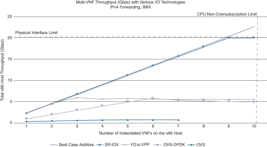
The results in Figure 10-16 highlight the current superiority of SR-IOV from a throughput perspective. For the other three techniques that are based on CPU-based switching, the total system throughput reaches a plateau, with FD.io and OVS-DPDK outperforming OVS. Note that a flattening of the total system throughput as VNFs are added implies that the average throughput per VNF in fact declines. This may again be operationally undesirable! Adding VNFs to the server impacts the throughput of the existing VNFs that are already passing traffic, and furthermore, the decline may not always be deterministic and predictable.
Figure 10-16 also shows that the attainable throughput per VNF is very respectable. In case of IPv4 forwarding only, multiple Gbps worth of throughput are forwarded by each VNF. In aggregate, the x86-based server is capable of delivering 10 Gbps of traffic or more depending on the number of VNFs and the chosen I/O technology. For the use cases described earlier in this chapter (branch virtualization or cloud connectivity in particular) this may be more than sufficient.
VNF Footprint Considerations
Many virtualized networking functions are configured in multiple ways in terms of number of vCPUs, virtual memory, virtualized interfaces, etc. The Cisco CSR 1000v, for example, is marketed with footprints of 1vCPU, 2vCPU, 4vCPU, and 8vCPU. Adding vCPUs to a VNF resource profile, however, does not imply that its throughput is scaling linearly. The internal VNF software architecture should be considered to assess the impact on the overall throughput and performance. In the case of the CSR 1000v, IOS XE running inside a VM only uses a single vCPU for the control plane process. So, increasing the number of vCPUs per VM in this case improves the processing that is allocated to the data plane, and for higher footprints for QoS and receive packet processing. But it does not scale the control plane in proportion to the data plane. Consider for example a comparison between a single 4vCPU CSR deployment and two 2vCPU CSR 1000v. In the former case, a single vCPU is being used for the control plane and three vCPUs are being used for the data plane processes. In the latter case, on the other hand, the total number of control plane threads generated by the two VMs is two, as is the number of data plane threads. Hence in the 2×2vCPU VNFs scenario, the control plane scales in proportion to the data plane, whereas the 1×4vCPU deployment scales only the data plane. Note however that a single control plane process for a 4vCPU deployment is sufficient for many deployments.
Multi-tenancy and Multi-function VNFs
A distinction can be made not only in how many features are executed together in a VNF, but also how many tenants (customers, departments, and partners) are configured to be processed within. This gives rise to four possible generic categories of deployment models:
Multi-feature multi-tenant (MFMT): VNFs are configured to execute multiple features on a given traffic flow. Furthermore, multiple tenants share a single VNF. This model, shown in Figure 10-17, is closest to the current physical edge infrastructure deployments.
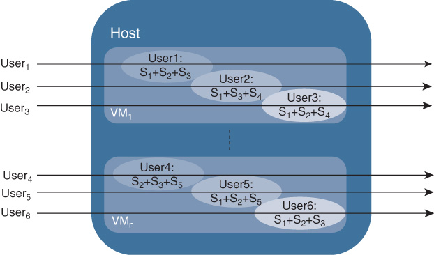
Figure 10-17 MFMT Chaining: Each VNF Executes Multiple Features per Tenant and Serves Multiple Tenants Multi-feature single-tenant (MFST): In this model, shown in Figure 10-18, each tenant is allocated a (ideally) single VNF, and all of the features applied to the tenant’s traffic flow are configured in this VM. Service chaining is no longer required.
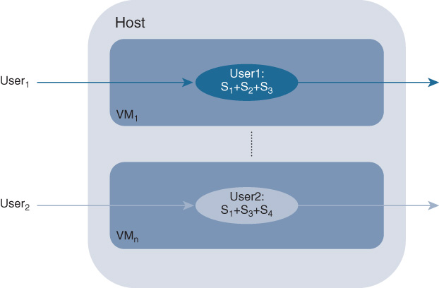
Figure 10-18 MFST Chaining: Each VNF Executes Multiple Features but Serves Only a Single Tenant Single-feature single-tenant (SFST): As shown in Figure 10-19, each tenant receiving services is allocated dedicated VNFs (that is, the VNFs are not shared or multi-tenanted between multiple customers). Furthermore, in case multiple networking services are applied to the tenant’s traffic streams, multiple VNFs are instantiated and the packet flow is chained between them. Note that not all VNFs are instantiated on the same server or even in the same geographical location. The service chains can span multiple servers distributed throughout the network.
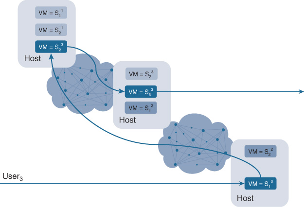
Figure 10-19 SFST Chaining: Each VNF Executes a Single Feature and Serves Only a Single Tenant Single-feature multi-tenant (SFMT): As shown in Figure 10-20, separate VNFs are instantiated to deliver a single service, but each VNF can serve multiple customers at the same time. For example, a single firewall VNF could be configured to protect multiple customers, each of these even requiring a different set of firewall rules. To apply multiple services to a tenant’s traffic flow, service chaining is again required, in this case even with multitenant awareness. Per-tenant service chains between the multi-tenant VNFs, IEEE 802.1ad (QinQ) VLAN trunks, or Network Services Header (NSH) based service chaining are possible options in this case.
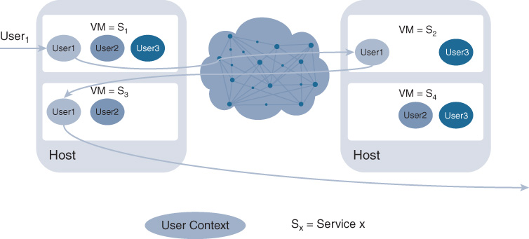
Figure 10-20 SFMT Chaining: Each VNF Executes a Single Feature but Serves Multiple Tenants
These deployment models are evaluated across different criteria, such as the number of VNFs required, whether service chaining is required or not, or the operational complexity of provisioning and monitoring the services.
In terms of the number of VMs required, the single-service single-tenant model requires the highest number of VNFs. The number required is the product of the number of tenants multiplied by the number of services per tenant. In some service provider use cases, the required number of VNFs in the SFST model may explode the TCO calculation. A multi-tenant multi-service model requires the least number of VNFs to be instantiated. The total number depends on the multi-tenancy capacity of the VNFs, and also assumes that the VNF is technically capable of executing all (or multiple) functions at the same time. The number of VNFs required in the remaining two models is between both extremes, with the number of VNFs of the single-tenant multi-feature model likely exceeding the multi-tenant single-feature model.
However, in terms of operational complexity, a different picture arises. Instantiation of single-tenant VNFs is typically simpler, since it only requires finding the hardware resources for the VNF(s) to be applied. In a multi-tenant deployment, onboarding an additional user requires the identification of an existing VNF with sufficient capacity. From this perspective, the SFST and MFST models offer more simplicity than the SFMT and MFMT models. Attributing orchestration complexity also to the task of instantiating the service chains then favors overall the MFST model. Failure detection and recovery models are also very different for these deployment models. Detecting the failure of an individual VNF is typically straightforward. However, the recovery complexity depends on the statefulness of features. Stateless features can more easily be failed over with mechanisms such as Hot Standby Routing Protocol (HSRP). A standby VNF takes on the traffic previously sent to the failed VNF. In a stateful environment, the flow state (e.g., for NAT sessions) must be kept synchronized between the active and the standby VNFs, which is difficult to achieve in real time, especially if VNFs are service chained across different data centers. Rebuilding the service chain also adds to the recovery complexity.
The preceding categorization illustrates the trade-offs that different deployment models offer. Consider many hybrid models in terms of multi-feature deployments. For example, NAT and firewall functions are often correlated, so they could be instantiated in a single VNF. Some features are also tenant agnostic, such as filtering globally blacklisted URLs. A VNF in this case does not need to have user awareness, and can be provisioned in a tenant-agnostic manner. This eliminates the need for tenant-aware VNFs for such services and reduces the total number of VNFs.
Transport Virtualization
Virtualization in Cisco DNA is not only relevant from an NFV perspective. Transport virtualization is crucial to allow the underlying physical network resources to be shared between many segments. Network segmentation is the capability of splitting a physical network into multiple logical partitions to keep the traffic from different groups of users/devices separated. The need for network segmentation in the enterprise is not new, but is becoming more important driven by the following recent interesting trends:
Internet of Things (IoT) and Bring Your Own IoT (BYOI)
Mobility in the context of the next-generation workspace
Take IoT as an example. IoT means a lot of traditionally non-IP “things” (such as healthcare instruments, HVAC and lighting apparatus, etc.) becoming IP-enabled and connected to the network. The enterprise infrastructure needs network partitioning to keep these different systems, and their administrative and security policies, completely separated. Guest access and user/device mobility is another simple but important use case where role-based access to internal resources needs to be guaranteed independently of where endpoints connect. Other common use cases for network segmentation are focused around security:
Security for multi-tenant dwelling: For example, airports with multiple airlines, a public-sector building with multiple agencies, or an enterprise building where departmental separation is required (e.g., engineering, sales, and human resources).
Regulatory compliance: For example, HIPAA in healthcare, PCI DSS in retail, Sarbanes-Oxley in finance, and many others.
Security for mergers and acquisitions: For example, keeping policy differentiation while dealing with overlapping IP addresses.
Cloud computing security: In a multi-tenant private or public cloud environment.
In order to satisfy new customer requirements and provide a solution to these important industry trends, network segmentation and virtualization is built into Cisco DNA to create logical separation of services at Layer 2 (L2) and Layer 3 (L3).
Network Segmentation Architecture
The Cisco segmentation architecture is based on three main components: network access control, network path isolation, and service edge, as illustrated in Figure 10-21.

The components and functions of the architecture are listed in Table 10-4.
Table 10-4 Functions of Transport Segmentation Components
Access Control |
Network Path Isolation |
Service Edge |
Policy-based access control |
Map VRFs to VLANs in access and service edge |
Shared or dedicated services |
Device authentication and authorization |
VRF segmentation and transport |
Inter VRF routing |
Classification and VLAN, SGT, and ACL enforcement |
Traffic isolation |
Isolated application environment |
Network Access Control
The access control function assigns an identity to the users/things connecting into the network so they are successfully assigned to a corresponding group. A group is used as a pointer to a set of permissions to allow for client/device differentiating access. In the context of network segmentation, the identity also provides the linkage to path isolation and virtualization techniques so that the permission is enforced throughout the network and not only at the access network device. Access control is composed of three main subfunctions:
Authentication: Authentication governs who (device/users) is trying to access the network. Authentication is done dynamically via IEEE 802.1X, via Web-Auth, or via network-based classification through network sensors. Alternatively, authentication is also done statically.
Authorization: Authorization defines the policies associated with the authenticated endpoint.
Policy enforcement: Policy enforcement associates a parameter to identify the endpoint in the rest of the network. This parameter could be a VLAN, a VRF, an ACL, or a security group tagging (SGT). It also enforces the policy in Cisco DNA by means of the policy enforcement point (PEP).
The Cisco Identity Services Engine (ISE) is the central platform for policy definition and management; it gathers advanced contextual data about who and what is accessing the network and then defines role-based access policies.
Network Path Virtualization
The term network path virtualization (or network virtualization for short) refers to the creation of multiple logical network partitions overlaid on top of a common physical network infrastructure. Each partition is logically isolated from the others and must appear to the end device/user as a fully dedicated network and provide all forwarding, security, and services expected from a physical network. Virtualization of the transport layer must address the virtualization both at the device level and at the interconnection level:
Device forwarding virtualization: The creation of VLANs for a switch and VRF for a router are both examples of creating multiple separated control and data planes on top of the same physical device.
Data path virtualization: The virtualization of the interconnection between devices. This is either a single-hop or multihop interconnection. For example, an Ethernet link between two switches provides a single-hop interconnection that is virtualized by means of IEEE 802.1Q VLAN tags. When an IP cloud is separating two virtualized devices, a multihop interconnection is required to provide end-to-end logical isolation and usually is implemented through tunneling.
The solutions to implement network path virtualization are classified in two main categories: policy based and control-plane based. These are elaborated in detail to follow.
Network Services Edge
The service “edge”’ is the place (central or distributed) where an enterprise deploys shared (DHCP, DNS, Internet access, etc.) or protected resources (that is, human resources databases). By default, the different logical networks (VPNs) built on top of the physical infrastructure are totally isolated from each other, so a mechanism to break this behavior is needed to allow for such shared resources.
The technical solutions to implement such shared services across virtualized networks include “prefix leaking” between routing tables using BGP or Easy Virtual Network (EVN) route replication and the use of a multicontext firewall. Providing a separate firewall per VPN allows the application and management of security policies for each virtual network independently, and it is hence the recommended deployment model. The analysis and discussion of the different deployment models of protecting access to shared services is out of the scope of this document.
Policy-based Path Segmentation
Policy-based path segmentation restricts the forwarding of traffic to specific destinations based on a defined policy and independently of the information provided by the forwarding control plane.
A classical example of policy-based segmentation is the use of VLANs and related ACLs assigned to a switch port or to a service set identifier (SSID) for wireless users. Groups of devices or users are assigned to VLANs and ACLs by static configuration or as a result of the authentication via IEEE 802.1X or other technologies. Although very common for use cases such as guest access, the main limitation of this Layer 2 virtualization solution is scalability: every time a VLAN is added, a series of parameters needs to be configured on the network devices (subnet, DHCP pool, routing, etc.).
Also, the logical isolation provided by VLANs ceases to exist at the boundary between Layer 2 and Layer 3 domains (the distribution layer devices). To extend the propagation beyond the access device, define and map a VRF to the VLAN. Figure 10-22 shows how different SSIDs can be mapped to VLANs and VRFs at the access layer.

Specific to wireless users, peer-to-peer blocking allows for a simple segmentation to control traffic between users connected to the same SSID by either dropping it or forwarding to the core network (the forwarding option is available only for traffic switched centrally at the WLC). Peer-to-peer blocking is used primarily for the guest wireless LAN (WLAN) and is configured at the SSID level.
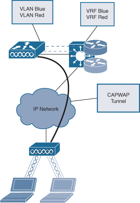
For Wi-Fi access, customers in the example use the Control and Provisioning of Wireless Access Points (CAPWAP) protocol to tunnel wireless traffic from APs to a centralized WLC on top of an IP cloud and to provide the desired segmentation. SSIDs broadcast over the air interface are mapped at the WLC to different VLANs as traffic enters the wired network. To add virtualization at Layer 3, the VLANs are also mapped to a separate VRF on the first hop layer device as shown in Figure 10-23.
The Cisco TrustSec solution overcomes the previously described limitations of solutions based on VLANs and ACLs and brings role-based access control (RBAC) to the network (to all devices in the network and not just the access device). TrustSec does not require changes in VLANs and subnets and works with the existing design. It is based on three functions:
Classification: SGT is assigned dynamically as the result of a Cisco ISE authorization. Alternatively, it can be assigned via static methods to map the SGT to a VLAN, subnet, or IP address.
Propagation: SGT information is either propagated inline (hop by hop) or via the SGT Exchange Protocol (SXP).
Enforcement: The network device enforces the policy via SGT ACLs dynamically downloaded from ISE.
A TrustSec SGT tag is inserted at L2 in the Ethernet frame in the Cisco Meta Data (CMD) field. For inline propagation, every node in the network must be able to interpret the TrustSec SGT rag and act on it. If the customer deployment does not require any-to-any segmentation, TrustSec can be used with the SXP protocol that allows the propagation of SGT information across a network that is not TrustSec enabled, as illustrated in Figure 10-24.

In summary, policy-based technologies do not rely on a control plane to transport the virtualization information and, in order to provide any-to-any segmentation, they are hop-by-hop in nature. This can result in more deployment and management complexity and limited scalability.
Control Plane–based Segmentation
Control plane–based techniques achieve path isolation by restricting the propagation of routing information to only subnets that belong to a VPN. To achieve control plane virtualization, a Layer 3 device must use the VRF technology that allows for the virtualization of the forwarding plane. Path virtualization technologies are classified based on how virtualization info is transported across the underlying network infrastructure:
Multihop path isolation: The virtualized devices are not directly connected and the virtualization info is carried across a network that is not virtualization-aware by the use of some Layer 3 tunneling technology. VRF-lite with GRE and MPLS VPN are examples of multihop solutions.
Single-hop path isolation: The VRF information in carried hop-by-hop and all the devices in the path need to be VRF-aware. VRF-lite and EVN are part of this category.
Multihop Path Isolation Techniques
VRF-lite with GRE is the simplest multihop technology, where a GRE tunnel is built between the routers that are part of the same virtual network and the VRFs are mapped to the GRE header. The implication is that GRE peering sessions need to be established among all the routers that are part of the virtual network, and if a router is added in a new site, all the existing routers need to be reconfigured. This can introduce scalability limits in the architecture. In addition, GRE tunneling may not be implemented in hardware (e.g., lower-end switches), further adding caveats to the architecture from a throughput perspective. For these reasons, VRF-lite with GRE did not see a big adoption among customers and is recommended only if deployed in a hub-and-spoke topology typical of guest access scenarios.
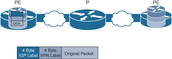
In an MPLS VPN design, the exchange of VPN routes is achieved by using an additional control plane element called Multiprotocol BGP (MP-BGP), which is an extension of the existing BGP-4 protocol. The MPLS core is made up of provider edge (PE) and provider (P) routers. At the PE level MP-BGP is used to exchange VRF routes. This is represented in Figure 10-25. MPLS VPN uses two sets of labels. The outer label represents the PE destination and is used by the PE routers to forward the packet through the network. The inner MPLS label is the VPN label and carries the VRF information. Only the destination PE interprets this VPN label and forwards the original packet on to the associated VRF.
Similar to a GRE tunnel overlay architecture, MPLS VPN based on BGP requires that a full-mesh neighbor relationship is established. The added configuration and management complexity of such full meshes are mitigated by the deployment of BGP route reflectors (RR) to relay the BGP information to other PEs in the network.
In case of an MPLS core, Virtual Private LAN Services (VPLS) is also used to provide an L2 pseudo wire service across the core network. VPLS mitigates the Spanning Tree Protocol (STP) problems that arise from the extensions of VLANs across multiple switches. However, VPLS also requires a full mesh of control plane communication and may result in MAC scalability limitations.
In summary, multihop segmentation techniques have the advantage to touch and virtualize only the devices at the edge of the network; the rest of the network ignores the VPN information. MPLS-VPN solutions scale very well and are suited to support any-to-any connectivity, relying on an underlay MPLS network based on BGP. This increases the learning curve and hence the deployment time and cost.
Single-Hop Path Isolation Techniques
An example of a single-hop (or hop-by-hop) isolation technique is VRF-lite. In this case, each and every network device is virtualized, together with all their physical interconnections. From a data plane perspective, the same concept of VLAN tags is used to provide logical isolation on each point-to-point link interconnecting the Layer 3 virtualized network devices. VRF-lite does not rely on MP-BGP or MPLS labels to carry the network segmentation information. Instead it requires the setup of hop-by-hop path isolation. Separate interfaces or subinterfaces must be provisioned for each virtual network on core-facing interfaces on an end-to-end virtualized path.
Multi-VRF is manageable for networks with a limited number of VRFs and hops in a virtual network path. As the number of virtual networks grows, new interfaces/subinterfaces and related IP addresses and routing need to be added. This increases planning and provisioning overhead, and that’s the reason why Cisco introduced Easy Virtual Network (EVN).
With Cisco EVN, path isolation is achieved by using a unique tag for each virtual network (VN). This tag is called the VNET tag and is operator assigned. An EVN device on the virtual path uses the tags to provide traffic separation among different VNs. This removes the dependency on physical/logical interfaces to provide traffic separation. VLAN-based segmentation with VRF-lite is illustrated in Figure 10-26.

As illustrated in Figure 10-27, only a single trunk interface is required to connect a pair of EVN devices and instead of adding a new field to carry the VNET tag in a packet. The VLAN ID field in IEEE 802.1Q is repurposed to carry a VNET tag.

In summary, VRF-lite and EVN are IP-based solutions that reuse familiar technologies like IEEE 802.1Q and Interior Gateway Protocol (IGP) routing protocols to provide virtualization. This provides a straightforward migration from existing campus architecture and a shorter learning curve (for example, because complexities arising from BGP are no longer needed).
Summary
This chapter discussed virtualization as an increasingly valuable tool in the network architect’s toolbox for building Cisco DNA. Both Network Function Virtualization (NFV) and transport virtualization (segmentation) fall into this category. The key takeaways in this chapter are as follows:
Network Function Virtualization allows you to deploy networking functions—be they control plane or data plane—in your network as virtual machines running on standard x86-based hosts. This reduces the overall TCO in your network by consolidating a number of appliances into a single x86-based server, diminishing operational overheads associated with running many hardware components. Possibly more importantly, the virtualization of network functions allows you to deploy network functionality within minutes when supported by the appropriate automation mechanisms.
VNFs can be dispatched per user group or segment, or even at an application-level granularity. They can be shared between multiple tenants, or dedicated to a single tenant. NFV thus offers increased deployment flexibility in your network!
The attainable performance of a single VNF is currently below the performance that is achieved with a dedicated hardware device, especially if the focus is on top-line throughput. Look at NFV as complementary to your hardware-based forwarding elements rather than as a replacement!
It is crucial for you to have a good understanding of the x86 hardware components, the operating system, and which components are shared among multiple VNFs. Understand the importance of the I/O path, since in many networking use cases the focus is on forwarding packets between the physical interfaces of the host. Understanding how the addition of a VNF to the host may affect already deployed VNFs is important to reach an acceptable operational model.
Segmentation of the data plane and control plane functions in the network is crucial, especially as IoT use cases are considered in Cisco DNA. Policy-based segmentation is enabled in Cisco DNA with Cisco TrustSec, where tags are applied to a packet flow based on the identity and authentication of a device or a user.
Together, NFV and transport virtualization provide you with a complete set of tools to virtualize your Cisco DNA network infrastructure even down to the application or user group level! The ride continues in the next chapter.