Chapter 18
Cisco DNA Virtualization Solutions: Enterprise Network Functions Virtualization and Secure Agile Exchange
Virtualization has been introduced throughout this book so far as one of the key tenets in Cisco Digital Network Architecture. Chapter 10, “Cisco DNA Infrastructure—Virtualization,” laid the foundation with an in-depth explanation of the technologies, highlighting both transport virtualization (segmentation) and the virtualization of network functions (NFV). This chapter elaborates on how Cisco offers virtualization solutions that leverage this technology to deliver the business benefits of aligning the network with your enterprise’s intent, of offering fast and flexible deployments for Cisco DNA services, and of lowering the total cost of ownership (TCO) in your network (e.g., through reduced branch site visits). This chapter explains the following:
Virtualization of branch architectures based on the Cisco Enterprise Network Functions Virtualization solution
Virtualization of policy-based connectivity to external domains in support of multicloud architectures
This chapter is thus organized around these two solutions. The section on Enterprise NFV builds on the technology foundation of Chapter 10 but applies these technologies in the context of solution and product details. Particular focus is given in this section on the system architecture details of the Cisco Enterprise Network Compute System (ENCS), which plays a crucial role in branch virtualization. The relevance of the Cisco Enterprise Network Functions Virtualization Infrastructure Software (NFVIS) is also introduced as an example of an operating system supporting NFV. The section on Enterprise Network Functions Virtualization (ENFV) also goes into details of service chaining in a branch virtualization context, and touches on the orchestration options for the Cisco ENFV solution.
The subsequent section in this chapter then concentrates on virtualizing external connectivity in Cisco DNA. The supporting Cisco solution for this use case is Secure Agile Exchange (SAE), which aims to combine virtualization with policy to allow you to define intent-based communication policies as you connect employees, partners, customers, or guests to applications hosted in your own private clouds, virtual private clouds, or even public clouds (i.e., consumed as a service).
There is also a section devoted to virtualization based on Cisco IOS XE. The Linux OS–based nature of IOS XE running on physical routers and switches also allows for the deployment of virtualized network functions (VNF) and containers directly within IOS XE. Details of this architectural variant of virtualization, are described toward the end of this chapter.
The Cisco Strategy for Virtualization in the Enterprise
In the Cisco vision, x86-based compute resources are available throughout the network wherever needed. x86-based hosts are already deployed across the network, in the access network, the core, or in distributed data centers. x86-based compute resources are also consumed by cloud providers. They are even already in the Cisco ASR 1000 Series routers, the Cisco ISR 4000 Series routers, and the Cisco Catalyst 9000 Series switches. Consequently, Cisco’s strategy for virtualization in the enterprise is to leverage these resources where available and necessary. Virtualization is not restricted to a single place in the network (PIN)!
The Cisco vision is to virtualize and automate the deployment of software-based services anywhere in the network, on any platform, to achieve simplicity, agility, and cost reductions. Virtualization needs to support an architecture that is
Secure, through the deployment of security VNFs where needed, as well as through a fully hardened virtualization solution.
Open, programmable and extensible, supporting VNFs not just from Cisco, but also from partners or third-party vendors. Published APIs are required to make the solution open and programmable, based on standards-based protocols such as REST, NETCONF, or RESTCONF at both the virtualization OS and the VNF level.
Policy-based, allowing for the alignment of the Cisco DNA enterprise network with your business intent, where VNFs are deployed in support of these policies at the user, application, or device level of granularity.
Cloud integrated, allowing you to consume resources in various cloud consumption models (private, virtual-private, public), with seamless and consistent deployment and operations.
In other words, virtualization needs to support the key tenets of Cisco DNA! Any network function (security, WAN, wireless, etc.) should be a candidate to run virtually, anywhere in the network (branch, campus, service provider points of presence [SP PoPs], data center, cloud), on any host that has x86-based compute resources available (x86, router, switch, cloud). In Cisco’s vision, you as a network architect or operator should have the ultimate choice of how to deploy a network function: both physical and virtual deployment options should be available to you with the same functionality and operational model. Finally, the solutions need to support flexible deployment models for enterprises and managed service providers (MSP).
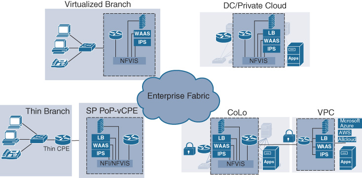
Figure 18-1 illustrates the main use cases for virtualization. As introduced in Chapter 10, branch virtualization brings about significant TCO reductions, by collapsing the number of hardware appliances to operate in the branch onto a single (or redundantly deployed) x86-based host. Data center/private cloud virtualization complements the flexibility of deploying application workloads as virtual machines (VMs) or containers by also applying the relevant network functions in a virtual form factor. Because such applications are increasingly hosted in public or virtual private clouds, virtualization also applies to those pins in an analogous manner. Public or virtual private cloud (VPC) connections can increasingly lead you to adopt a multicloud strategy, and motivate virtualization in a co-location facility where connections to several cloud providers and environments are consistently underpinned with policy-based virtualized service chains. Virtualization in Cisco DNA is not restricted to your own operations. Service providers also offer virtualized network functions; for example, virtualized customer premises equipment (CPE) that runs in distributed SP PoPs or in centralized SP data centers, and allow for functionally reduced “thin” CPE to be deployed in your enterprise sites. Such a consumption model also may bring about overall cost reductions for both the enterprise and the MSP.
Cisco Enterprise Network Functions Virtualization
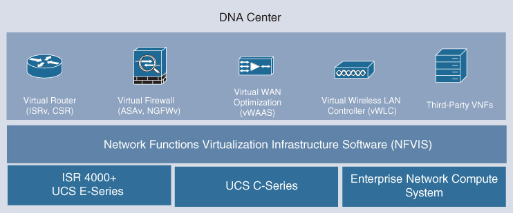
Let’s now delve into the details of the Cisco Enterprise Network Functions Virtualization (ENFV) solution.1 This solution offers a full solution stack to virtualize enterprise branch environments. The stack consists of four main building blocks:
1 https://www.cisco.com/c/en/us/solutions/enterprise-networks/enterprise-network-functions-virtualization-nfv/index.html
An orchestration environment to allow easy automation of the deployment of virtualized network services, consisting of multiple VNFs. The orchestration environment for ENFV is integrated into Cisco DNA Center.
The VNFs that provide the desired network functionality, or even non-networking software applications, required at a deployment location.
The Network Functions Virtualization Infrastructure Software (NFVIS) platform to facilitate the deployment and operation of VNFs and hardware components. NFVIS is based on a standard Linux operating system distribution, but enhances this with additional NFV-optimized functions. For example, a lifecycle management function facilitates the instantiation of VNFs, and the coupling of them into a service chain.
x86-based compute resources to provide the CPU, memory, and storage required to deploy and operate VNFs and run applications.
The stack is illustrated in Figure 18-2.
The Cisco ENFV solution offers a fully systems-integrated environment to virtualize branch functions, while also providing a variety of deployment options. For example, from an orchestration perspective, ENFV is an integral part of the Cisco DNA automation and assurance functions offered by Cisco DNA Center. All the layers in the ENFV solution stack are fully solution tested. Similarly, functional flexibility is provided by
Offering Cisco VNFs that are consistent with the physical network elements2
2 The Cisco ISRv offers the same functions as the physical Cisco ISR 4000 Series routers. Both are based on IOS XE. Similarly, the Cisco ASAv has functional and operational consistency with the Cisco ASA appliances. This consistency applies to other virtualized Cisco offers as well.
Supporting third-party VNFs and application workloads
Allowing the solution to run on a variety of Cisco hardware hosts
The following sections provide details on each of these layers in the Cisco ENFV solution, starting in a bottom-up manner from the hardware layer all the way to the orchestration layer.
Details on Virtualization Hardware
Three platform options currently form the basis of ENFV by providing the necessary compute resources: the Cisco ISR 4000 Series routers equipped with Cisco Unified Computing System (UCS) E-Series compute blades, Cisco UCS C-Series servers, and the Cisco Enterprise Network Compute System (ENCS). These hardware options, depicted in Figure 18-3, allow you to choose the right platform for your branch virtualization environment.
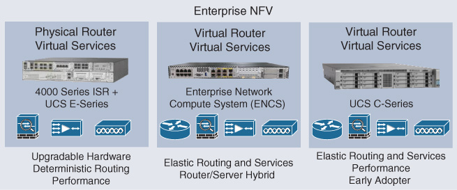
The first option based on the Cisco ISR 4000 Series routers installed with a Cisco UCS E-Series compute blade is optimized for deployments where either a Cisco ISR 4000 Series router is already installed (i.e., a brownfield environment) or your operational model has a preference for a physical router. In this deployment option, the NFVIS operating system is installed on the Cisco UCS E-Series compute blade, whereas the Cisco ISR 4000 Series host is operating on the Cisco IOS XE software. Cisco Enterprise Network Functions Virtualization (ENFV) concentrates on the UCS E-Series compute blade, where Layer 4–7 functions such as firewall, WAN optimization, and intrusion prevention system/intrusion detection system (IPS/IDS) are virtualized using the Cisco Adaptive Security Virtual Appliance (ASAv) Series, the Cisco Virtual Wide Area Applications Services (vWAAS), or the Cisco Firepower Threat Defense Virtual (FTDv) software solutions, respectively, on top of NFVIS. Virtualization of the routing functionality is not required in this option because it is performed by Cisco IOS XE in the Cisco ISR 4000 Series host. This hardware option in the Cisco ENFV portfolio also allows you to leverage the Cisco ISR 4000 Series voice capabilities that come with Cisco IOS XE. Table 18-1 provides specific hardware details on the various Cisco UCS E-Series blades for the Cisco ISR family of routers.
Table 18-1 Cisco UCS E-Series Hardware Details
|
UCS-E104S M2 |
UCS-E160S M3 |
UCS-E160D M2 |
UCS-E180D M2 |
Processor |
Intel Xeon (Ivy Bridge) E3-1105C v2 (1.8 GHz) |
Intel Xeon Broadwell DE processor D-1528 (1.90 GHz) |
Intel Xeon (Ivy Bridge) E5-2418L v2 (2 GHz) |
Intel Xeon (Ivy Bridge) E5-2428L v2 (1.8 GHz) |
Core |
4 |
6 |
6 |
8 |
Memory |
8 to 16 GB DDR3 1333 MHz |
8 to 32 GB VLP DDR4 RAM |
8 to 48 GB DDR3 1333 MHz |
8 to 96 GB DDR3 1333 MHz |
Storage |
200 GB to 2 TB (2 HDD) SATA, SAS, SED, SSD |
200 GB to 4 TB (2 HDD) SATA, SAS, SED, SSD |
200 GB to 3 TB (3 HDD) SATA, SAS, SED, SSD |
200 GB to 5.4 TB (3 HDD) SATA, SAS, SED, SSD |
RAID |
RAID 0 and 1 |
RAID 0 and 1 |
RAID 0, RAID 1, and RAID 5 |
RAID 0, RAID 1, and RAID 5 |
Network port |
Internal: two GE ports External: one GE port |
Internal: two GE ports External: two 10 GE ports (1000/10000) |
Internal: two GE ports External: one GE port PCIE Card 4 GE or one 10 GE Fibre Channel over Ethernet (FCoE) |
Internal: two GE ports External: two GE ports PCIE Card 4 GE or one 10 GE FCoE |
In some cases, your branch deployments may already have a data center–grade Cisco UCS C-Series server installed. For example, in a retail environment, enterprise applications supporting point-of-sale, video surveillance, or voice communications may already be hosted on an x86-based platform. The same Cisco UCS C-Series server can be leveraged in this case to also run virtualized network functions. In this model, the server’s operating system is upgraded to run NFVIS, giving you the flexibility to run VNFs alongside the enterprise application workloads. Note that a virtual routing function may be required in this case to provide transport connectivity across the WAN. An instantiation of the Cisco Integrated Services Virtual Router (ISRv) (or the CSR 1000v) is typical in this model. Deployment of a DC-grade server in the branch offers the advantage of significantly more compute resources. A standard Cisco UCS C-Series server offers up to 44 compute cores, with hundreds of gigabytes of configurable memory. On the other hand, the power and cooling requirements of DC-grade servers are often higher than for branch-optimized network elements, especially when considering a redundant deployment option with two or more servers.
The Cisco ENCS Series offers an attractive alternative. The Cisco ENCS Series is purpose-built for branch virtualization. It offers x86-based compute resources to run multiple VNFs, but in a form factor that is optimized for the branch from a size, power, and cooling perspective. Like the previous hardware options, the Cisco ENCS Series is also powered by Cisco NFVIS. NFVIS is thus a common convergence layer abstracting a variety of hardware options and providing common operating system functions optimized for branch virtualization. The Cisco ENCS Series hosts come in two main variants: the Cisco 5100 Series and the Cisco 5400 Series. The Cisco 5100 Series is cost-optimized for smaller branch virtualization use cases. The four-core AMD processor offers the ability to instantiate up to two VNFs (depending on the VNFs resource requirements). This model has reduced interface capabilities; for example, it does not provide the Cisco Network Interface Module (NIM) slot and has no integrated L2 switch. The Cisco 5400 Series hosts come in three variations offering from 6 to 12 CPU cores. The Cisco 5406 provides 6 CPU cores clocked at 1.9 GHz. The Cisco 5408 offers 8 CPU cores clocked at 2.0 GHz. The Cisco 5412 has the highest number of CPU cores—12 in total—clocked at 1.5 GHz. Table 18-2 summarizes the various Cisco ENCS hardware models and their resource capacities from a core and memory perspective.
Table 18-2 Cisco ENCS Hardware Details
|
5100 Series |
5400 Series |
CPU vendor/model |
AMD Merlin, Falcon, RX-421ND |
Intel Xeon Broadwell D-1500 Series |
CPU cores/frequency |
4-core @ 3.4 GHz |
6-, 8-, 12-core with Hyperthreading @ 1.5–2.0 GHz |
CPU L2 cache size |
2 MB |
1.5 MB per core |
Memory |
16–32 GB |
16–64 GB |
Storage (M.2 SATA) |
64–400 GB |
64–400 GB |
Storage (SFF) |
— |
Two disks with RAID (SATA, SAS, SED, SSD) |
Dimensions |
12.7" × 10" × 1RU |
17.5" × 12" × 1RU |
WAN options |
4 × GE, Cellular |
2 × GE, Cellular, T1, DSL, Serial |
LAN |
— |
8-port switch with optional PoE |
Hardware offload |
— |
Supported for VM to VM Traffic |
Lights-out management |
— |
Built-in CIMC |
Figure 18-4 reveals more details about the Cisco ENCS running Cisco NFVIS as its operating system.
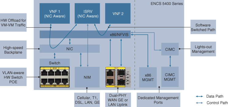
The hardware provides various physical interfaces:
A console port.
A Cisco Integrated Management Controller (CIMC) port for lights-out management. CIMC provides access to boot-level functions, allowing configuration of the hardware below the operating system layer, as well as associated monitoring.
A management port providing direct access to the NFVIS operating system.
Up to four Ethernet uplink ports (WAN or LAN), two of which are RJ-45 based and two of which are small form-factor pluggable (SFP) based.
Up to eight Ethernet LAN ports connected to a physical integrated switch
A single NIM slot for connectivity other than Ethernet
The NIM slots in the Cisco ENCS deserve particular attention: they allow you to connect the Cisco ENCS to the WAN using standard Cisco NIM modules, such as the 3G/4G NIM or the T1/E1 NIM. Although the Cisco ENCS is fundamentally an x86-based host, it still satisfies non-Ethernet WAN interfaces. This makes the Cisco ENCS particularly useful for branches that still have non-Ethernet WAN interfaces provisioned, or if media diversity is required for uplink redundancy. Note that the NIM slot is controlled by the Cisco ISRv directly. The driver software for the NIM interfaces is embedded in the Cisco ISRv routing VNF, not in the Cisco NFVIS software. This implies that the NIMs can only be leveraged in conjunction with the deployment of a Cisco ISRv VNF.
Figure 18-4 also shows the built-in network interface card (NIC) in the Cisco ENCS. This NIC provides a built-in, high-speed backplane to which all VNFs and application workloads can be connected. The NIC supports single-root I/O virtualization (SR-IOV, discussed in Chapter 10), and offers a hardware-assisted path to pass traffic between VNFs. For example, if traffic needs to traverse two or more VNFs with SR-IOV support, the NIC is provisioned to forward the packets in hardware instead of utilizing NFVIS for software-based service chaining. Such a hardware-based VNF-to-VNF path does not use the x86 cores for switching. With SR-IOV-supported VNFs, the available x86-based compute resources are dedicated to VNF processing, rather than having to spend CPU cycles for software switching. In other words, the built-in NIC gives you greater deployment flexibility not only by offering a faster hardware-assisted service chaining path, but also by providing the ability to deploy more VNFs onto the host.
The integrated switch is controlled by the NFVIS Linux operating system. It thus offers standard functionality that you may expect at this level, such as specifying the hardware configuration (RAID, boot order, BIOS settings), monitoring and troubleshooting at the hardware layer, power-cycling the platform, or performing disaster recovery. The physical switch is not governed by IOS XE (e.g., by the ISRv directly) and thus does not provide extended switching functionality that is common in physical IOS XE–based switches (e.g., the Cisco Catalyst 9000 Series switches).
NFVIS: An Operating System Optimized for Enterprise Virtualization
The second major building block in the Cisco ENFV solution stack is the operating system for the various x86-based hosts. Cisco Network Functions Virtualization Infrastructure Software (NFVIS) is based on a standard Linux operating system with Kernel-based Virtual Machine (KVM). KVM extends Linux to VMs to run with unmodified operating systems (i.e., KVM is an example of a type-2 hypervisor). KVM offers core virtualization infrastructure to present the VMs with virtual CPU, virtual memory, virtual storage, or virtual interfaces. Each VM is associated with private virtualized hardware—network cards, disks, or even graphics adapters. Linux with KVM also includes Quick Emulator (QEMU), Libvirt, and other associated processes.
Particularly noteworthy is the additional software switching capability that KVM offers to the solution. The Open vSwitch (OVS) that is part of the Linux KVM environment provides connectivity for the VNFs to the underlying physical interfaces or to each other. OVS is the default switching path in all NFVIS-based systems if SR-IOV is not supported. For example, if physical interface models in Cisco UCS-C servers or if the VNFs do not support SR-IOV, packets are switched using OVS. This is illustrated in Figure 18-4 as the “Software switched path.”
Virtualizing the underlying host resources using KVM, however, is not sufficient to optimize the virtualization of network functions. To optimize your experience for the branch virtualization use case targeted by ENFV, NFVIS offers additional functions such as:
Zero-Touch Provisioning (ZTP): Imagine you want to virtualize all the branches in your enterprise network—possibly ranging in the hundreds or even thousands. The ZTP functionality embedded into NFVIS allows an NFVIS-based system (Unified Compute System UCS E-Series, Unified Compute System UCS C-Series, ENCS) to automatically call home to a plug-and-play server to complete its bootup process and obtain site-specific configurations. Upon completion of the power-on sequence, the NFVIS-based system boots a minimal configuration that has the necessary Plug and Play (PnP) details to find the PnP server. The PnP server information is either statically configured, learned via DHCP Option 43 through the DHCP process, obtained via DNS, or default to a cloud-based redirection tool from Cisco. The NFVIS-based host then establishes a highly secure connection to the PnP server, authenticating against credentials based on the device’s hardware serial number. This prevents rogue devices from automatically connecting to your network. The orchestration system (Cisco DNA Center) then provides further device configurations for the x86-based host, or even instantiates the actual VNFs that are associated with the site by association with the host’s serial number.
Lifecycle management and VNF health monitoring: VNF lifecycle management functions are essential for the use case of branch virtualization. This capability in NFVIS allows for the automatic instantiation and ongoing monitoring of the VNFs in your branch. The NFVIS Lifecycle Manager (LCM) loads VNFs based on the profile that is associated with the host. It subsequently monitors the liveliness of each instantiated VNF as well as the communication path (service chain). In case of failures, it attempts to stop and restart (reboot) the affected VNFs, or performs additional remedial actions such as raising syslog alarms. The lifecycle management functionality can also be leveraged to insert additional VNFs into the service chain as part of a day N operations change.
The LCM functionality in NFVIS is fully automated based on REST API calls from the Cisco DNA Center orchestration system.
Service chaining: One of the key benefits of branch virtualization is that multiple network functions are collapsed inside a single x86-based host in VNF form factors. This of course implies that the traffic is steered within the system through these various VNFs—i.e., traffic is associated with a service chain. NFVIS instantiates the desired service chains based on the profile that is designed for the system at the orchestration and management layer.
The service chaining functionality within NFVIS currently leverages bridges. Traffic is forced to traverse a number of VNFs in sequence by association of the interfaces with different bridges. Further details are provided a bit later in the section “Service Chaining and Sample Packet Flows.”
Open APIs: Many of the operations previously outlined are assumed to be driven from a centralized management and operations system—Cisco DNA Center. The overall ENFV solution is integrated based on open APIs. At the host layer, NFVIS exposes APIs for all the functions previously outlined, supported by the associated API transport mechanisms. The NFVIS APIs are called from northbound systems (such as Cisco DNA Center) via REST or NETCONF. APIs are offered to register VNF images, deploy VNFs, start and stop VNFs, create and manage software bridges, monitor host resources (CPU, memory, storage, I/O), log details, manage users, manage the NFVIS configuration, etc. Full details about the NFVIS APIs are available in the API Reference for Cisco Enterprise Network Functions Virtualization Infrastructure Software.3
3 https://www.cisco.com/c/en/us/td/docs/routers/nfvis/user_guide/b-api-reference-for-cisco-enterprise-nfvis/b-api-reference-for-cisco-enterprise-nfvis_chapter_00.html
Web server: NFVIS also has an embedded web server to allow connectivity to a particular NFVIS host through HTTP Secure (HTTPS). This is particularly useful if you want to manage a system through a local management tool or locally through APIs.
Device management: NFVIS packages tools in support of x86 management (for example, a resource manager).
Statistics: Statistics collection in NFVIS is also enhanced above the standard Linux functionality. Tools like syslogd, snmpd, and collectd assist in statistics collection and reporting.
A final noteworthy point that differentiates NFVIS from a standard Linux operating system concerns security. NFVIS supports secure boot to authenticate, for example, an ENCS system using the secure unique device identifier (SUDI).
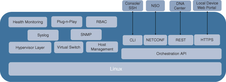
Figure 18-5 illustrates the key functional building blocks of NFVIS, and highlights the additional functionality above and beyond the standard Linux OS.
After booting, NFVIS automatically sets up an internal network infrastructure to prepare the system for communication between its different components. The virtual software switching path is used for this purpose to create a bridge and a VLAN for the WAN ports (WAN-br and WAN net respectively), for the LAN ports (LAN-br, LAN net), and for the internal management network (Mgmt-br, Mgmt net). The latter is particularly critical to subsequently monitor the VNFs from NFVIS. This management network is not intended for exterior reachability of the VNFs—it is for internal NFVIS monitoring only. External reachability of instantiated VNFs is provided via port forwarding of one of the host’s IP address (NFVIS Management IP or WAN IP). Figure 18-6 illustrates the internal networking connectivity for the Cisco ENCS 5400 Series.
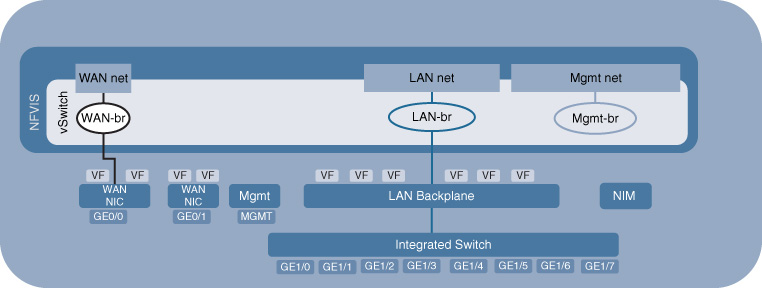
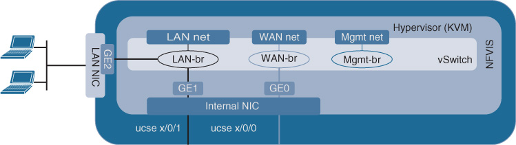
Figure 18-7 shows the corresponding default network setup for the UCS E-Series blade. Note that in this case an internal NIC connects the blade to the ISR 4000 Series host. This internal NIC has two configurable internal Gigabit Ethernet (GE) interfaces. The single GE0 is connected to the WAN ports of the ISR 4000 Series host using the default NFVIS-controlled WAN bridge. The single GE1 connects to the ISR 4000 Series LAN ports. The NFVIS-created LAN bridge connects the local physical ports on the UCS E-Series blade (GE2 and higher) to the internal LAN GE (GE1), allowing traffic to reach the VNFs through either the local UCS E-Series ports or through the ISR 4000 Series LAN ports.
NFVIS consumes one of the x86-based hosts CPU cores, as well as 2 GB of RAM and 10 GB of storage. Take this into account when deciding on which hardware platform to use. A four-core ENCS 5104 has three cores available for VNF onboarding, sufficient for one instance of Cisco ISRv plus an additional one-vCPU VNF or application workload of your choice. The Cisco 5412, on the other hand, has 12 physical cores available, leaving you more flexibility to onboard a variety of VNFs. More details on NFVIS are available in the Cisco Enterprise Network Functions Virtualization Infrastructure Software Configuration Guide.4
4 https://www.cisco.com/c/en/us/td/docs/routers/nfvis/user_guide/nfvis-config-guide/nfvis-user-guide_chapter_0110.html
Virtualized Network Functions
The third major building block in the Cisco ENFV solution are the VNFs and application workloads. The solution accommodates any commercially available VNF, such as the Cisco Integrated Services Virtual Router (ISRv), Cisco Adaptive Security Virtual Appliance (ASAv), Cisco Firepower Threat Defense Virtual (FTDv), and Cisco Virtual Wide Area Application Services (vWAAS). VNFs from third-party vendors can also be onboarded and chained into a service. Similarly, because NFVIS is based on a standard Linux OS with KVM, any application workload can also be hosted on an NFVIS-based system. This is particularly useful if you want to run some application workloads locally in your branch, such as Cisco Unified Survivable Remote Site Telephony (SRST), print servers, packet generators, etc.
Cisco Integrated Services Virtual Router
The dominant network function in any branch environment is routing for connectivity to the WAN. Here, the Cisco ISRv provides the same functionality as physical IOS XE–based routing platforms (ISR 4000 Series, ASR 1000 Series). The Cisco ISRv leverages the same IOS XE software architecture, just in a virtualized form factor. You can therefore leverage all of the extensive routing features, such as Open Shortest Path First (OSPF), Enhanced Interior Gateway Protocol (EIGRP), Intermediate System to Intermediate System (IS-IS), and Border Gateway Protocol (BGP), quality of service (QoS) mechanisms, security functionality (ACLs), encryption (IPsec-based VPNs), or even features such as zone-based firewalls, network address translation (NAT), and deep packet inspection (Cisco Application Visibility and Control [AVC]). IOS XE has over 3000 features, so it is truly a Swiss Army knife for networking, and with the Cisco ISRv also in a virtual form factor.
The ISRv is available in different form factors to accommodate varying resource and throughput requirements.5 Two-vCPU and four-vCPU versions are available, typically consuming two and four physical CPU cores respectively,6 allowing for throughputs up to 1 Gbps of forwarding. Of course, this throughput is dependent on feature configuration, but is more than sufficient for most of today’s branch use cases. Cisco ISRv throughput is licensed in different throughput limits; 50 Mbps, 100 Mbps, 250 Mbps, and 1 Gbps licenses are available. The license is enforced inside the VNF by means of an egress shaper. The aggregate egress bandwidth leaving the Cisco ISRv VM out of any port is monitored, and shaped to the licensed bandwidth limit.
5 Cisco Integrated Services Virtual Router Data Sheet, https://www.cisco.com/c/en/us/solutions/collateral/enterprise-networks/enterprise-network-functions-virtualization-nfv/datasheet-c78-736768.html
6 Hyperthreading is not recommended in ENFV, hence the virtual CPU requirement directly correlates to physical CPU cores.
Cisco Adaptive Security Virtual Appliance
The Cisco ASAv offers virtual firewall capabilities for branch deployments. Again, the software is carrying forward the functionality from the corresponding hardware-based appliance. With the exception of clustering and multicontext support, all of the stateful firewall inspection capabilities are available inside a Cisco ASAv virtual machine. Examples are flow- or connection-based inspections, high-speed NAT support, unicast and multicast routing (including IPv6), Authentication Authorization, and Accounting (AAA) functionality, Cisco TrustSec, mobile network inspection (Diameter, Stream Control Transmission Protocol [SCTP], GPRS Tunneling Protocol [GTPv2]), remote-access VPNs, etc.
The Cisco ASAv also comes in various footprints. At the low end, one vCPU and 1 GB of RAM are required to deliver up to 100 Mbps of forwarding. The one-vCPU/2-GB Cisco ASAv10 and four-vCPU/8-GB Cisco ASAv30 offer intermediary footprints for throughputs of up to 1 Gbps and 2 Gbps respectively. At the high end, the Cisco ASAv50 forwards up to 10 Gbps of traffic, requiring eight vCPUs and 16 GB of RAM.
For further details on the Cisco ASAv, see, for example, the ASAv data sheet.7
7 https://www.cisco.com/c/en/us/products/collateral/security/adaptive-security-virtual-appliance-asav/datasheet-c78-733399.html
Cisco Firepower NGFW Virtual
The Cisco Firepower NGFW Virtual (NGFWv) extends the firewall capabilities of the Cisco ASAv to also offer a stateful next-generation firewall, supporting IPS/IDS capabilities. URL Filtering, Cisco Advanced Malware Protection (AMP), and Cisco Application Visibility and Control (AVC) are some of the key capabilities that NGFWv offers above and beyond the standard firewall functions. Network traffic is inspected with content awareness (files and file types) and correlated with context, such as user or applications, to detect malware or other intrusions.
The Cisco NGFWv is available in a four-vCPU footprint requiring 8 GB of RAM and 50 GB of disk space.
As you might expect, the functionality is also aligned with the corresponding physical appliance to allow you to seamlessly choose between a virtual or physical deployment.
Further details on the Cisco NGFWv are available in the Cisco Firepower NGFW data sheet.8
8 https://www.cisco.com/c/en/us/products/collateral/security/firepower-ngfw/datasheet-c78-736661.pdf
Cisco Virtual Wide Area Application Services
The next VNF that is popular in branch deployments is the WAN optimization function provided by Cisco vWAAS VNF. Cisco vWAAS offers WAN acceleration techniques such as TCP flow optimization, data redundancy elimination (DRE) and caching, and payload compression.
Cisco vWAAS is offered in multiple models with different vCPU, RAM, and storage requirements. For example, Cisco vWAAS-750 requires two vCPUs, 4 GB of RAM, and 250 GB of storage for up to 8 Mbps of WAN bandwidth; Cisco vWAAS-6000 requires four vCPUs, 8 GB of RAM, and 500 GB of storage for up to 90 Mbps of WAN bandwidth; and Cisco vWAAS-12000 requires four vCPUs, 12 GB or RAM, and 750 GB of storage to deliver up to 310 Mbps of WAN bandwidth.
Additional technical details on Cisco vWAAS are provided at Cisco.com.9
9 Cisco Virtual WAAS Technical Overview, https://www.cisco.com/c/en/us/td/docs/app_ntwk_services/waas/vwaas/vwaas-623/vwaas-install-config/v-intro.html
Cisco Prime Virtual Network Analysis Module
The Cisco Prime Virtual Network Analysis Module (vNAM) is another type of VNF that proves beneficial in a virtualized branch deployment. It allows you to inspect traffic and gain Layer 4 through Layer 7 visibility into traffic flows. It provides detailed information and visibility on how applications in your branch are performing. Cisco vNAM leverages the Network-based Application Recognition (NBAR) engine to identify applications and obtain specific statistics. Cisco vNAM provides capabilities to view short- and long-term network usage on a per-application, per-host, per-conversation basis. It integrates with Cisco TrustSec to learn about user and application groups. In combination with Cisco vWAAS, a vNAM VNF demonstrates the effectiveness of the WAN optimization functionality.
The Cisco vNAM VNF requires two vCPUs, 3 GB of RAM, and 100 GB of disk space.
The Cisco vNAM data sheet offers additional technical details.10
10 https://www.cisco.com/c/en/us/products/collateral/cloud-systems-management/prime-virtual-network-analysis-module-vnam/data_sheet_c78-723214.html
Cisco Virtual Wireless LAN Controller
Virtualizing the Wireless LAN Controller (WLC) in a branch environment is another popular candidate of VNFs in the Cisco branch virtualization solution. For deployments that today see a redundant pair of physical WLCs at a branch, virtualization of the WLC function may reduce overall costs for licensing and operation of appliances.
The Cisco Virtual Wireless LAN Controller (vWLC) provides functional consistency with the physical WLC appliance. It offers control, management, and troubleshooting capabilities for wireless access points, supporting the Cisco FlexConnect solution. Management of the radio frequencies (RF) is one of its important capabilities. Additional functions of the Cisco vWLC include securing the Configuration and Provisioning of Wireless Access Points (CAPWAP) tunnel between the AP and the vWLC, supporting voice communications, or allowing for fault tolerance to a backup controller.
The Cisco vWLC comes in two form factors: the small version requires one vCPU, 2 GB of RAM, and 8 GB of disk space. This version scales to 200 access points and up to 6000 clients. The large version increases the scale to 3000 access points and 32,000 clients, and consumes two vCPUs, 8 GB of RAM, and also 8 GB of disk space.
Further details on the Cisco vWLC are found in its data sheet.11
11 https://www.cisco.com/c/en/us/products/collateral/wireless/virtual-wireless-controller/data_sheet_c78-714543.html
Note that a key advantage of maintaining the same software architecture between physical networking appliances and their virtualized counterparts previously mentioned is operational consistency. Once you have instantiated a Cisco ISRv, ASAv, NGFWv, vWAAS, or vWLC features are configured in exactly the same manner as on the physical platforms. This also makes the VNFs easily integrated into any existing backend management system. After the VNFs are reachable via IP, any logging, statistics collection, and troubleshooting procedures remain the same. This facilitates the introduction of Cisco ENFV into your existing enterprise environment. Remember that it should not matter whether a network function is deployed in a physical appliance or virtually. This should be your choice based on the architectural and business requirements.
Third-party VNF Support
The Cisco VNFs covered thus far are currently at the top of network functions deployed in a branch, but they are by no means the only candidates! After all, the key benefit of virtualization in the branch is that it gives you as the network architect or operator the flexibility to deploy any VNF or even application workload…provided it is supported under a Linux KVM environment! The Cisco ENFV solution stack is fully supportive of this principle. It has been designed from the ground up to run third-party VNFs or application workloads on top of Cisco NFVIS.
Support for third-party VNFs comes in two forms. First, the requirements that any VNF has to fulfill to be compliant with the NFVIS OS are well documented and specified. Just as you have OS requirements to run applications on a Microsoft Windows or an Apple iOS system, the NFVIS VNF Specification12 describes the details for third-party VNFs. For example, it requires compliance with the NFVIS’s Linux and KVM versions, chipset support, and API or OVS version numbers. Table 18-3 provides insight into the basic OS requirements that third-party VNFs need to be compliant with.
12 https://developer.cisco.com/site/nfv/#the-ecosystem-program
Table 18-3 Cisco NFVIS Requirements for VNFs
Requirement Category |
Requirement |
Max vCPU per VNF |
NFVIS: Function: ((Number of platform physical cores – 1) × 2) Explanation: NFVIS requires one core. CSP-2100: MaxBMvCPU = (number of physical cores) – 1 Hyperthreading is disabled on CSP-2100. |
Minimum number of vCPUs |
1 |
Maximum vMemory allowed per VNF |
NFVIS: Function: MaxVNFvMem = Physical memory – 2 GB Explanation: NFVIS needs 2 GB of RAM. CSP-2100: MaxVMvMem = Physical memory – 4 GB Explanation: CSP 2100 needs 4 GB of RAM. |
Maximum vHDD |
NFVIS: Function: MaxVNFvHDD = Available-SSD/HDD – 15 GB Explanation: NFVIS needs disk to store images, logs, etc. CSP-2100: CSP 2100 Function: MaxVMvHDD = Available-SSD/HDD – 16 GB Explanation: CSP 2100 needs disk to store images, logs, etc. |
Storage controller supported |
VirtIO 1.0 or IDE |
Maximum disk size volume per VNF |
NFVIS: Function: Available SSD/HDD – 15 GB CSP-2100: Hardware needs to be RHEL 7.3 certified. |
Hyperthreading |
On/Allowed |
Chipset support |
Hardware needs to be CentOS 7.2 certified. |
64-bit hardware |
Required |
Hypervisor support |
NFVIS: KVM CentOS 7.2 CSP-2100: KVM RHEL 7.3 |
Virtualization |
NFVIS: Libvirt 1.2.8 or higher CSP-2100: Libvirt 2.0.0 or higher |
API |
QEMU 1.5.3 or higher |
vSwitch |
NFVIS: OVS 2.3.2 or higher CSP-2100: OVS 2.4.0 or higher |
A VNF manifest file in XML format can be accommodated to inform the Cisco NFVIS about all the files in a third-party VNF package: VNF properties file, image files, or one or more bootstrap files. The VNF properties file is also in XML format, and describes the type of VNF (router, firewall, etc.), name, version, disk-bus types, and root disk image format, among other properties. Perhaps most importantly, the VNFs resource requirements in terms of minimum and maximum number of vCPUs required, memory requirements, support for SR-IOV, bootstrap configurations, etc. can also be itemized in this file.
The second form of support for third-party VNFs and application workloads is provided through the Cisco NFV Open Ecosystem. This is a certification program for partners and interested parties to certify interoperability of candidate VNFs with Cisco NFVIS. Third-party VNFs can be qualified by a partner following the NFVIS VNF Test plan.13 This test plan offers a workflow to test the loading of a candidate VNF into the NFVIS image repository, file format compliance and packaging, interface onboarding, VNF boot, management connectivity, software upgrades, etc.
13 https://pubhub.devnetcloud.com/media/nfv/docs/ThirdPartyNFVEcosystemCertificationTestPlanv1_6.pdf
Service Chaining and Sample Packet Flows
Spinning up network functions in virtual machines to replace physical network appliances is only half of the story in Network Functions Virtualization. The other half is how to connect VNFs with each other—in other words, how to “internalize” the physical connectivity that used to exist between the hardware-based network elements inside an x86-based host. This topic is often captured under the label “service chaining.”
In a purely physical network architecture, you establish connectivity between devices using cables (typically Ethernet) within a branch. You also set up the corresponding Layer 2 and Layer 3 configurations to steer user traffic to the desired devices and to enable connectivity at both of these respective layers.
As multiple VNFs are hosted on the same x86-based system, physical connectivity between them may no longer be required. The hypervisor environment on top of which the VNFs are riding provides a virtual switching capability, as discussed in Chapter 10. And the Layer 2 connectivity between VNFs is now configured at the hypervisor layer by means of virtual bridges and virtual networks. Virtual bridges create a Layer 2 domain between the virtual NICs of the VNFs. The vNICs are associated with a range of MAC addresses. Virtual networks inside the host specify a Layer 2 segment that is typically associated with VLAN range.
Figure 18-8 shows the default internal connectivity of an NFVIS host by example of a Cisco ENCS. The physical WAN interfaces of the host are connected by default to a virtual WAN bridge, leveraging the virtual switch of the KVM hypervisor. Associated with this bridge is also a network (wan-net). Both the WAN bridge and the WAN network have DHCP enabled by default. Also, the Gigabit Ethernet interface GE0/0 is by default associated with the WAN bridge.
The physical LAN interfaces are also connected to a virtual bridge (lan-br) and an associated VLAN network. Note that all of the physical LAN interfaces that are exposed on the front panel of the ENCS share the same bridge.
VNFs are by default connecting to one (or both in case of a single VNF in the system) of these internal bridges to receive traffic from the physical interfaces. In the virtual branch use case described herein, a virtual router typically receives traffic from the WAN interfaces via the virtual WAN bridge. Alternatively, if the virtual router instance supports SR-IOV, a direct virtual Peripheral Component Interconnect Express (PCIe) connection can be established to the SR-IOV virtual function (VF), bypassing the KVM hypervisor for virtual switching. Recall that SR-IOV relieves the hypervisor from having to switch packets in software between the physical interface and a virtual interface of a VNF. However, this technology requires support both of the physical interface (which is a given in Cisco ENCS, for example) and of the particular virtual routing VNF (such as the Cisco ISRv).
Traffic from the physical LAN interface is typically connected to one of the L4–L7 VNFs using the LAN bridge. (If the virtual router is the only VNF hosted on the system, it may be connected to both the physical LAN and WAN interfaces via the virtualized LAN and WAN bridges.) The “trick” in a virtualized system architecture is to leverage virtual bridges and virtual networks to now steer traffic between the desired VNFs. To this end, one or more bridges are created in the switch with their associated VLAN networks, as illustrated in Figure 18-8. Anchoring VNFs in different VLAN networks (and their associated bridges) then forces traffic to traverse the various VNFs in the desired order for processing.
Figure 18-8 also illustrates an internal management bridge. This bridge is created by default in NFVIS to allow the ongoing monitoring of the instantiated VNFs. It is not accessible from the outside. The physical management port shown in Figure 18-8 represents the connectivity to the NFVIS host itself, which is used to access and mange NFVIS. The physical CIMC and console ports for ENCS are not represented in the figure.
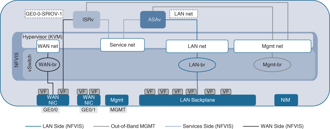
A sample packet flow through a simple service chain with a virtual router (Cisco ISRv) and a virtual firewall (Cisco ASAv) is illustrated in Figure 18-9. In the packet flow direction WAN to LAN, packets arrive in the WAN interface. Because the Cisco ISRv supports SR-IOV, packets are directly passed to the ISRv for processing. The VNF internal ISRv configuration manipulates the traffic flow according to the configured features (e.g., routing, QoS, NAT, etc.). The Cisco ISRv then has a virtual interface that is connected to the service network (service-net) out of which traffic is then forcibly forwarded toward the LAN side. Because the only downstream VNF connected to service-net is the virtual firewall, packets are switched to the Cisco ASAv for processing. The firewall policies configured in the ASAv are applied to the traffic flow. Again, the firewall VNF has a VLAN network configuration that forces traffic to egress toward lan-net, and thus ultimately allows packets to egress the ENCS system on a physical LAN port.
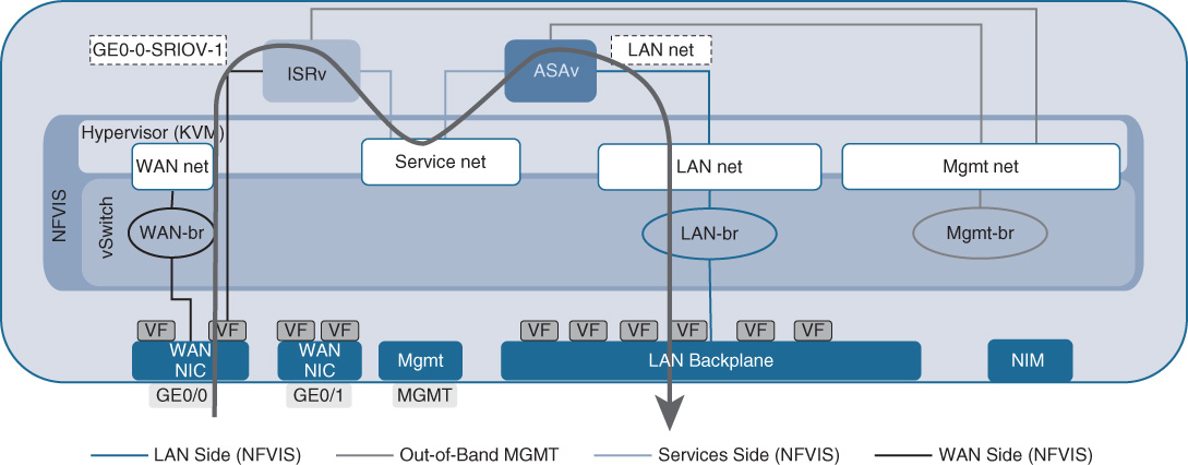
In this configuration, the fact that each VNF is anchored in different VLAN networks and that each VLAN connects “only” two VNFs creates a service chain.
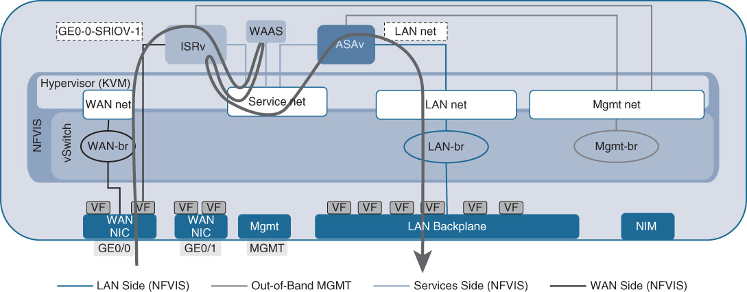
A slightly more complex example is shown in Figure 18-10. In this case, a virtual WAN optimization VNF in the form of Cisco vWAAS is also instantiated. Cisco vWAAS cooperates with the Cisco ISRv by means of an efficient protocol (AppNav) to optimize WAN traffic. The Cisco ISRv performs the redirection function for traffic, allowing for application of redirection filters. The Cisco vWAAS VNF performs WAN optimization on the traffic flows, including Transmission Control Protocol (TCP) flow control optimizations, caching, and data redundancy elimination. The AppNav control protocol running between Cisco vWAAS and the Cisco ISRv communicates the state of the WAN optimization engine to the ISRv, such as session state and configured WAN optimization services that are applied by a particular vWAAS instance. This tight, optimized coupling between the Cisco ISRv and Cisco vWAAS affects the packet flow. In the packet flow direction WAN to LAN, packets arrive from the WAN interface at the Cisco ISRv. The Cisco ISRv by its AppNav configuration filters traffic to be redirected to Cisco vWAAS. Traffic is optimized by Cisco vWAAS, returned to the Cisco ISRv, and forwarded to the virtual firewall (ASAv). In the return direction, traffic from the LAN interface is first processed by the Cisco ASAv in the example. From there, packets are forwarded to the Cisco ISRv, where the AppNav filter and redirection are once again determining which flows need to be optimized by the Cisco vWAAS VNF. Note that the service VLAN network (and its associated bridge) provides connectivity between all three of these VNFs. The service chain in this case is enforced by a combination of the AppNav protocol and the configured VLANs.
Transparent Versus Routed Service Chains
A further distinction in service chaining can be made based on the configuration of the participating VNFs. The two options are
Routed service chains
Transparent service chains
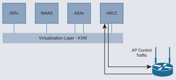
In a routed service chain, each VNF in the chain has its own IP address, and the VNFs may use IP routing to direct traffic toward the next VNF in the chain. This is also the case when VNFs are addressed directly by the clients or server endpoints—that is, when the VNF becomes the actual destination of a traffic flow. Consider for example a Wireless LAN Controller (WLC) running in a virtual machine. In this case, the access points communicate with the vWLC directly via IP. Access points learn the IP address of the vWLC via the usual mechanism, Address Resolution Protocol (ARP), and subsequently send packets with that address as the destination IP. This is illustrated in Figure 18-11.
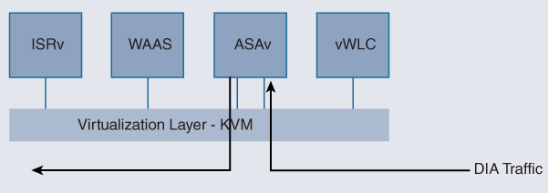
In contrast, in transparent (inline) mode, VNFs are configured to be transparent to the packet flows from an IP perspective. The clients and servers do not generate packets directly destined to a VNF. The VNF is not the final destination of a traffic flow. Instead, VNFs provide a network function that operates on the packet flow transparently to the client and the server. When a client or a server is trying to reach an IP address on the opposite side of such a VNF, packets flow through this VNF transparently. Even operations like ARP broadcasts are forwarded through the VNF so that another device can respond to the ARP requests. Clients are not required to know about the presence of a VNF, and thus do not require specific configurations. Figure 18-12 illustrates an example of a virtual Cisco ASAv firewall. Direct Internet access (DIA) traffic must pass through a firewall before it is forwarded. The Cisco ASAv is configured in transparent mode, eliminating the need of the source or the destination to know about its existence. Traffic is nonetheless forced through the virtual firewall by the service chain architecture, albeit unbeknown to the endpoints.
Orchestration and Management
Virtualizing the branch infrastructure presents a different orchestration and management situation to you as an operator: functions that were dedicated to a particular hardware appliance now are running in a virtual machine, and multiple of such virtual machines share the same underlying hardware resources, potentially impacting each other.
First, from an orchestration and automation perspective, you therefore need to deploy a generic x86-based host for VNFs—in all of your (possibly thousands) branch locations. In contrast to standard data-center x86-based workload hosts, the NFV server platform may be configured to optimize the execution of network functions, rather than application workloads. Monitoring functions of generic x86-based hosts may also be new to your organizational unit to understand the behavior of the hosts as it processes multiple VNFs. For the Cisco ENFV solution, the options for automating and orchestrating an NFVIS-based server are as follows:
Device level (individual system)
Web-based graphical user interface for an individual NFVIS system
Traditional mechanisms (command-line interface, APIs)
Network level (multiple systems)
Centralized network-wide automation based on Cisco DNA Center
Second, once you have the VNFs instantiated, you need to configure, monitor, and manage them. Luckily, in most cases the fact that many VNFs are derived from their physical brethren implies that the same (or very similar) orchestration and management tools and procedures apply. For example, for Cisco vWAAS VNF or the NGFWv VNF, the WAAS Central Manager (WCM) or the Firepower Management Center (FMC) is leveraged, respectively, to also help you manage already instantiated VNFs. Also, traditional monitoring mechanisms like SNMP, NetFlow, CLI show commands, or Embedded Event Manager (EEM) scripts can also be leveraged if supported by the particular VNF.
The remainder of this section focuses on the NFVIS host management and monitoring options in the Cisco ENFV solution.
NFVIS GUI (Per System)
Let’s start with the operator portal provided with NFVIS and illustrate various samples of operations that you can perform on a particular system. Recall from the functional overview of NFVIS that one of the components added on top of the standard Linux (with a KVM hypervisor) environment is a web server. This capability is leveraged in Cisco ENFV to allow you to manage and monitor an NFVIS-based host locally. Figure 18-13 shows the initial landing screen (Home) when you log into the NFVIS host using a standard browser.
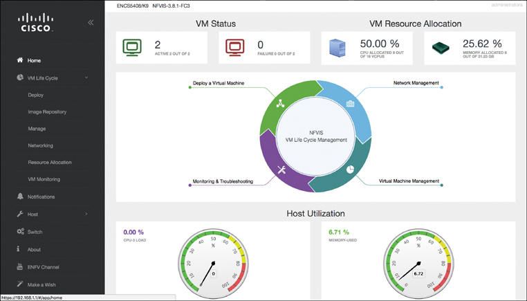
The Home screen provides information on the main state of the host, such as the number of active VNFs, failure summaries, and resource utilizations for the CPU cores and memory. The circle in the center of the landing screen represents the workflow lifecycle to allow you to drill into various actions: deploying a VNF on the local system, managing the network interfaces and internal software switches, managing virtual machines, or performing monitoring and troubleshooting activities.
These respective workflows are also accessible from the menu on the left of the landing page. You are presented with options to perform virtual machine lifecycle management, monitor notifications, configure and diagnose the x86-based host, observe and configure the internal switch settings, display information about the NFVIS system itself, or access the help videos (ENFV channel).
One of the important actions you may want to perform on the NFVIS host is to deploy a virtual machine. To do so, expand the VM Life Cycle menu on the left and choose the Deploy option. The VM Deployment screen, shown in Figure 18-14, allows you to see the existing VNFs deployed on the system on a canvas, as well as a list of VNF images that are registered with the host. Dragging and dropping a registered VNF type from the top onto the canvas allows you to trigger the instantiation of an additional VNF on the system. You can also manipulate the internal network settings by dropping a network onto the canvas and graphically controlling the connections to the instantiated VNFs.
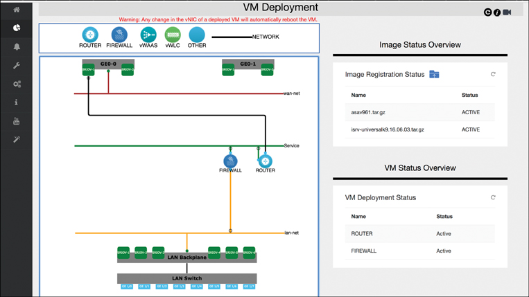
Note that the VNF of type OTHER allows you to deploy a generic workload VM (e.g., Linux or Windows).
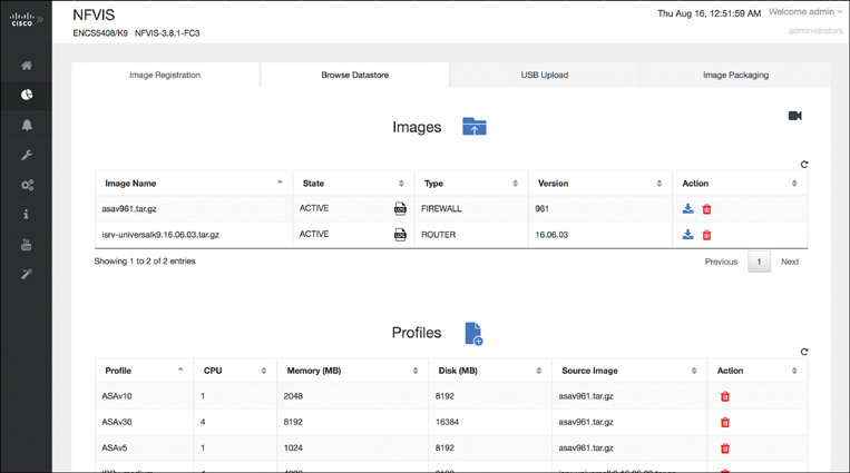
Choosing Image Repository from the VM Life Cycle menu allows you to register different VNF types in the system, such as different virtual routers, firewalls, WAN optimization VNFs, etc., as shown in Figure 18-15. The generic VNF software images are uploaded (e.g., in .tar or .qcow2 format) and then used to create VNF profiles. In this step, you can take a generic VNF image to generate an actual VNF instance with a specific number of vCPUs, memory reservations, or disk storage capacity.
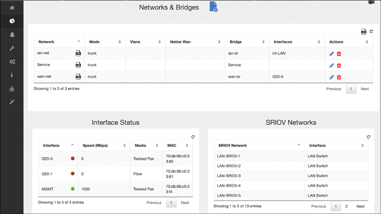
Choosing the Networking option from the VM Life Cycle menu provides you with options to view and manipulate the network interface and internal bridge settings, as shown in Figure 18-16. Notice the internal bridges that connect VNFs to the physical interfaces and to each other. You can create additional networks and edit (or even delete) existing networks. The status and settings of physical interfaces and the virtualized SR-IOV networks are also displayed on this screen.
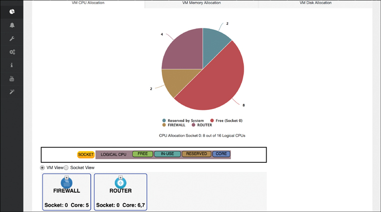
Another example of the operations that are performed locally on an NFVIS system using the portal is shown in Figure 18-17, the Resource Allocation screen. The physical resources allocated in the system are displayed for the CPUs, memory, and disk. This allows you to correlate the shared hardware resources to the actual VNFs that are instantiated. For example, you can see which VNF instance is running on which CPU core (and socket), and how much of the available total memory or disk is consumed by a particular VNF instance.
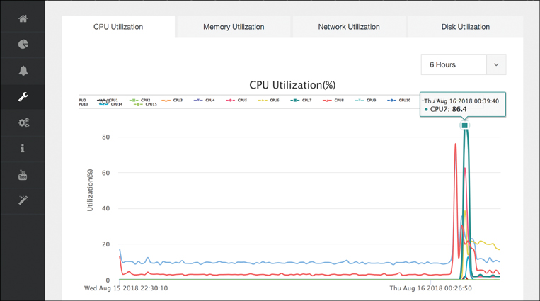
You can observe the resource utilization from a host perspective by expanding the Host menu and choosing Monitoring, as shown in Figure 18-18. Whereas the last example showed you the correlation of the physical resources to the instantiated VNFs, in this view the actual CPU, memory, network interface, and disk utilizations are displayed over time. In combination, both of these views allow you to better understand what is happening on the NFVIS host both from an overall system perspective and from a particular VNF perspective.
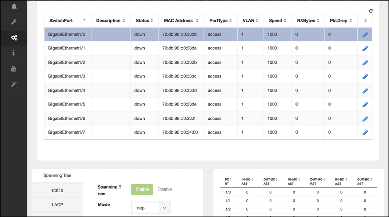
The final example of operations you can perform on a per-NFVIS-system basis is shown in Figure 18-19, the Switch Settings screen. Recall from the hardware options overview that an ENCS host provides an integrated physical switch that is leveraged to connect multiple physical interfaces to the VNFs, as well as to perform VNF-to-VNF switching in hardware. In this portal screen, you can monitor and manipulate the details of these physical interfaces and switches. You can enter the switch’s Spanning Tree settings, VLAN configuration, and Link Aggregation Control Protocol (LACP) parameters. Packet statistics by port for unicast, multicast, and broadcast packets in both directions (in and out) are also displayed.
Cisco DNA Center (Network Level)
The second option to automate the deployment and operation of VNFs in the branch is provided by Cisco DNA Center. This platform allows you holistic operations of multiple devices in your enterprise network from a single pane of glass. Cisco DNA Center supports all stages of the enterprise network operations lifecycle.
Cisco DNA Center allows you as a network designer to standardize the network designs of your branch, campus, and WAN environments. Cisco DNA Center offers workflows to specify the desired network architecture and functionality, and save the resulting profiles in a library for subsequent deployment. This allows you to increase the conformity of your network to standardized network designs—an absolute MUST to automate network operations across hundreds or even thousands of sites and devices.
For your network deployment teams, Cisco DNA Center offers support to automate the roll-out and instantiation of network functions (both physical and virtual), for example by leveraging zero-touch deployment (network plug-and-play, PnP) to add network elements to the network. Of course, Cisco DNA Center helps you to ensure that the deployments conform to the intended architecture prescribed in the design phase. The Cisco DNA controller platform enables the automation of the network infrastructure as a whole system, rather than network element by network element.
Cisco DNA Center also enables you to operate your network based on policies. The respective Policy workflows allow you to specify policies pertaining to user groups, device groups, and even application groups. Supported by Cisco Identity Services Engine (ISE), access policies can regulate which users, devices, or applications are granted access to your network. For all admitted endpoints, access control policies can be authored to further regulate the relationship between user groups, application groups, or device groups. Moreover, application policies can govern how traffic between users, devices, and applications is to be treated by the network.
Finally, Cisco DNA Center provides assurance tools and mechanisms to understand the ongoing behavior of your network. The Cisco DNA Assurance capabilities provide you with an in-depth understanding on how users, devices, or applications experience the network. Any issues that the Cisco DNA assurance engine detects is flagged, and can also be traced back over time. This is where the network-wide view of Cisco DNA Center proves extremely valuable. Rather than analyzing any issues on a per-network-element basis and correlating events between network elements yourself, the Cisco DNA Assurance capabilities allow you to understand the behavior of the network as an entity. For example, a connectivity issue for wireless clients is viewed from the wireless client to the application, including diverse functions like DNS, DHCP, the Wireless LAN Controller (WLC), etc. that may play a role in the end-to-end communication path. Of course, key performance indicators (KPIs) for individual network elements are also collected and available for you to fully grasp the state of your enterprise network.
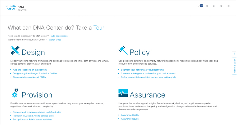
Figure 18-20 shows the initial landing page of Cisco DNA Center, showing the principal workflows for network design, policy, provisioning, and assurance. Supporting tools to perform network discovery, list the inventory of devices, display the topology, manage software images or licenses, or authoring CLI templates are also shown.
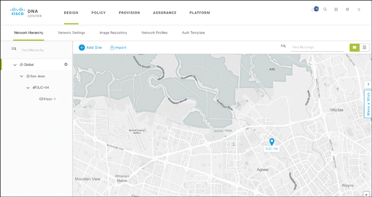
From an ENFV perspective, the Cisco DNA Center workflows for network design and provisioning are particularly relevant. The workflows are mostly generic from a network function perspective, allowing you to focus on the deployment and operation of network functions regardless of whether these are deployed as a physical appliance or in a virtual form factor. For example, as illustrated in Figure 18-21, the Cisco DNA Center Design workflow allows you to view the network hierarchy in terms of sites and buildings, which of course also pertains to the deployed VNFs. Similarly, generic network settings (details about DNS, DHCP, Network Time Protocol [NTP], and AAA servers, for example), device software image management, or license management are functions that Cisco DNA Center offers that apply to either physical or virtual network functions.
The capability to specify the desired network architecture from a routing perspective is entered in the Cisco DNA Center Design workflow under Network Profiles. Figure 18-22 illustrates the current library of specified designs, with metadata details such as the name of the profile, its type (routing & NFV, switching, wireless), the sites that this profile is associated with, as well as options to edit its details or even delete the profile from the library. Adding a new profile is achieved by clicking Add Profile in the upper-right side. Note that the site attribute is particularly important for the deployment of profiles. Sites, as created in the network hierarchy, provide the common anchor to link the desired network architecture with devices that are actually deployed. The network designer specifies a network profile and details the list of sites to which this profile pertains. When devices are dispatched for deployment, they are also associated with a site.
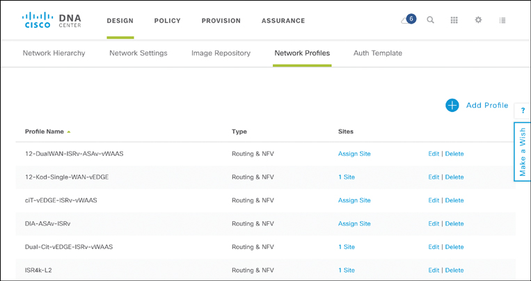
Because both network elements (physical or virtual) and network profiles are associated with a site, Cisco DNA Center correlates the two and ensures
That the right device is deployed at the right site (and flags if a discrepancy occurred), as learned from the PnP process.
Application of the appropriate configuration for the network element that the designer has prescribed in the network profile. In the case of ENFV, Cisco DNA Center instantiates the desired VNFs as per the profile, and creates the necessary virtual switching connectivity between them. It also pushes an initial VNF configuration if specified for in the profile during the design phase.
Adding a network profile for routing allows you to describe the intended WAN architecture. Prescribe the details of the WAN connectivity to the service providers in the initial screen of the ENFV Design workflow. Figure 18-23 illustrates the various options for the WAN connectivity: single router or redundant router configuration to one or more SPs. In this step of the workflow, the hardware platform is selected from a list of registered devices. For example, for ENFV you can select among the ISR 4000 Series router with a UCS E-Series compute blade, an ENCS system, or a UCS C-Series server—all of which support NFVIS. Selection of one of these devices then allows you to describe the intended virtual system architecture as the workflow continues.
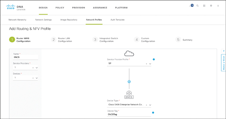
Cisco DNA Center recognizes that the selection of a Cisco ENCS as a hardware platform implies the additional specification of a virtualized system profile, and thus presents you with different options than if a physical Cisco ISR 4000 Series router were selected.
Figure 18-24 shows the canvas that appears for virtualized profiles. You can choose to characterize not only the (virtual) routing function, but also one or more additional Layer 4–Layer 7 VNFs or application workloads. The Cisco DNA Center ENFV canvas thus allows you to select among the registered VNF types (e.g., router, firewall, WAN Optimization), and shows you the prescribed connectivity from an NFVIS perspective between the VNFs and to the physical interfaces of the underlying host (both LAN and WAN interfaces).
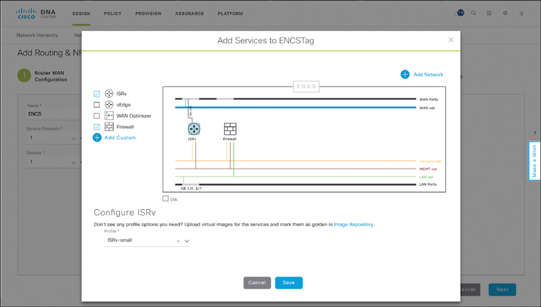
For each of the VNFs in the profile, you can specify details about a particular VNF—for example, select a Cisco ISRv virtual router, with resource profile “small.” The resource profiles determine the amount of hardware resources required for the specific VNF in terms of vCPUs, virtual memory, or virtual storage. Cisco DNA Center uses this information both during the design phase and during the deployment phase to ensure that sufficient hardware resources are actually available to run the network function, or flag an issue in case they are not.
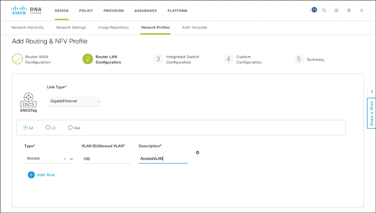
Proceeding through the Cisco DNA Center Design workflow for ENFV then allows you to provide details on the desired LAN configuration, the specifics for the built-in switch in case the hardware is a Cisco ENCS, or even to provide custom configuration details for the system. For example, under the Router LAN Configuration step, shown in Figure 18-25, you place interfaces into either L2 or L3 mode by type and, in case of the former, restrict the range of allowed VLANs.
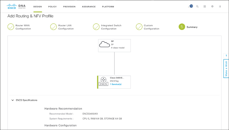
At the end of this Design workflow, Cisco DNA Center summarizes the profile on a single screen, showing routing connectivity to the WAN SP, the type of NFVIS host selected, and the VNFs, LAN configuration, etc. that have been specified under the profile as well as their details. Cisco DNA Center also summarizes the total physical CPU, memory, and storage requirements for the profile to ensure that the selected hardware type offers sufficient resources. The Summary screen of the ENFV Design workflow in Cisco DNA Center is shown in Figure 18-26.
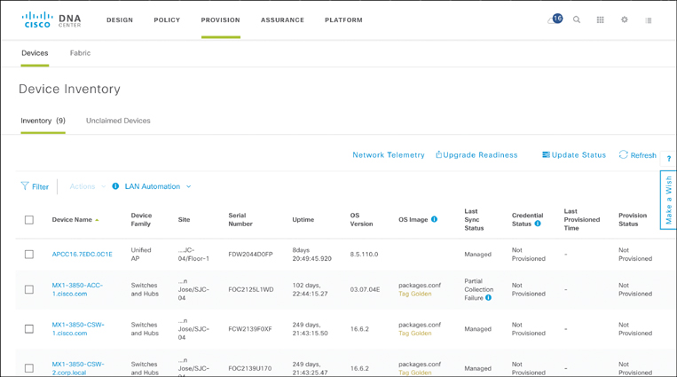
The deployment of physical and virtual network functions in a site is assumed to happen in an independent workflow. The Provision workflow assumes that you have acquired the hardware and shipped it to a particular site. In the example of ENFV, a Cisco ISR 4000 Series router with a UCS E-Series compute blade, an ENCS system, or a UCS C-Series server is assumed to be installed in the desired location, connected to a power source and the relevant LAN and WAN connections, and powered up. The PnP process of NFVIS then ensures that the device registers with Cisco DNA Center. Upon successful completion of this process, the device appears in Cisco DNA Center’s inventory as an “unclaimed” device.
The Provision workflow of an NFVIS-based system, as shown in Figure 18-27, enables you to associate the deployed device with a site—and this is really all that is required to then continue the provisioning of the NFVIS-based system as per the profile! Recall that the site-specific architecture is characterized by the designer in the Design workflow, and stored in a profile that associates to a site. By also associating an NFVIS system to a site, Cisco DNA Center finds the correct profile to apply, and thus learns about the VNFs or application workloads to be instantiated on the virtualized system. The rest is history! Cisco DNA Center communicates with the NFVIS host using REST APIs, brings up the VNFs as per the profile with their optional day 1 configuration files, creates the internal connectivity (VLANs, bridges, etc.) as per the profile, and establishes the connectivity to the physical LAN and WAN ports. Done!
Configuring and Monitoring of an NFVIS Host Using Traditional Mechanisms
The previous two sections illustrated, respectively, how an individual NFVIS-based host is managed and operated using a per-system GUI and how Cisco DNA Center is leveraged to automate the deployment of ENFV from a network-wide single pane of glass. The third option briefly discussed here is to leverage traditional monitoring and management mechanisms: the command-line interface (CLI), Management Information Bases (MIBs), or the Cisco Integrated Management Controller (CIMC).
Any NFVIS-based hosts can be configured and monitored using CLI commands by, for example, using the NFVIS’s physical management port or the physical WAN ports. On a Cisco ENCS system, the management port is assigned a default IP address of 192.168.1.1 for access to NFVIS. In fact, any operation that is executed by the local GUI or the centralized Cisco DNA Center has a corresponding NFVIS command. As listed in the Cisco Enterprise Network Functions Virtualization Infrastructure Software Command Reference,14 the command categories at the NFVIS host level are as follows:
14 https://www.cisco.com/c/en/us/td/docs/routers/nfvis/command/b-nfvis-command-ref.html
Banner and Message Commands
System and IP Configuration Commands
PnP Commands
Resource Commands
Networks and Bridges Commands
VM Lifecycle Management Commands
Internal Management IP Commands
System Monitoring Commands
System Operations Commands
System Time Commands
System Portal Commands
System Routes Commands
System Log Commands
Span Session and Packet Capture Commands
Upgrade Package Commands
Factory Default Reset Command
Syslog Commands
SNMP Commands
RADIUS Commands
TACACS Commands
User Management Commands
Secondary IP and Source Interface Commands
Ports and Port Channel Commands
Support Commands
As an example, the statistics for the physical host resources are displayed using the show system-monitoring host command:
show system-monitoring host [cpu | disk | memory | port] stats
Similarly, the VNF-specific statistics are shown using the show system-monitoring vnf command:
show system-monitoring vnf [cpu | memory] stats
Recall that VNFs are accessed by NFVIS via the internal management network and bridge. These are specifically created for such internal system monitoring activities. The NFVIS CLI commands are not only useful to display the system state for monitoring. They are used to set parameters as well, as illustrated in the following command sequence. The system settings commands allow you to specify the IP address of the NFVIS host and to set the default gateway, as shown ina Example 18-1.
Example 18-1 Configuration Example for the WAN IP Address in the NFVIS CLI
nfvis# configure terminal
nfvis(config)# system settings wan ip address 10.192.133.11 255.255.255.0
nfvis(config)# system settings default-gw 10.192.133.1
nfvis(config)# end
NFVIS also supports a wide range of MIBs that are queried using SNMP. The following list gives you a sample of the available MIBS:
CISCO-UNIFIED-COMPUTING-EQUIPMENT-MIB
CISCO-UNIFIED-COMPUTING-FAULT-MIB
CISCO-UNIFIED-COMPUTING-MIB
CISCO-UNIFIED-COMPUTING-MEMORY-MIB
CISCO-UNIFIED-COMPUTING-NOTIFS-MIB
CISCO-UNIFIED-COMPUTING-PROCESSOR-MIB
CISCO-UNIFIED-COMPUTING-STORAGE-MIB
CISCO-UNIFIED-COMPUTING-TC-MIB
ITU-ALARM-TC-MIB
ENTITY-MIB
IF-MIB
SNMPv2-MIB
SNMPv2-CONF-MIB
SNMPv2-SMI-MIB
SNMPv2-TC-MIB
SNMP-FRAMEWORK-MIB
INET-ADDRESS-MIB
CISCO-SMI
CISCO-TC
CISCO-PROCESS-MIB
As you would expect, SNMP GET commands (GET, GETNEXT, GETBULK) are issued by a network management system (NMS) to gather data from the NFVIS host. SNMP SET commands allow you to modify the value of an object variable, and SNMP notifications generate unsolicited notifications for trap events. SNMPv1, SNMPv2c, and SNMPv3 are supported.
Finally, for the Cisco x86-based hosts, the Cisco Integrated Management Controller capabilities are also available to perform low-level hardware-centric management operations. CIMC allows you to configure and view hardware-related parameters, such as setting the management IP address, viewing and upgrading BIOS versions, manipulating the boot sequence, power-cycling the server, monitoring the health of the hardware components, or even accessing the KVM console.
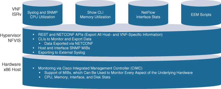
Figure 18-28 summarizes the various management and operations options at the x86-based host, NFVIS, and VNF level. Recall that this section focuses on the NFVIS system aspects, and not on the management and operations of the VNFs. Of course, once these are up and running, traditional mechanisms to operate the VNF internals are applicable. This is also illustrated in Figure 18-28 by calling out the VNF syslog, SNMP, CLI, NetFlow, or EEM script capabilities.
Virtualizing Connectivity to Untrusted Domains: Secure Agile Exchange
The concept of branch virtualization is also generalized and applied to secure the connectivity from your enterprise network to untrusted domains. The Cisco Secure Agile Exchange (SAE) solution extends the concepts of branch virtualization to apply VNFs and service chaining based on policies between “consumers” of application traffic and “providers” (that is, where applications are hosted). Relationships between consumers and providers are expected to become increasingly complex as
Applications move into the cloud (VPC) or are consumed as a service (for example, SaaS)
Enterprises partner with more and more external organizations to participate in the delivery of digitalized business services
Customers and employees become increasingly more mobile, wishing to consume services from anywhere on any device
The Cisco SAE solution leverages virtualization and service chaining with a focus on securing such increasingly complex communication relationships. The following section motivates the Cisco SAE solution, followed by a section detailing the solution building blocks.
Motivation for the Cisco SAE Solution
Consider a traditional demilitarized zone (DMZ) architecture in the data center. Typically, connections from the outside world are gathered to arrive in a DMZ, where security functions such as firewalling, intrusion detection and prevention, web security, etc. are applied to protect the enterprise assets from unwanted attacks.
Today, this part of your network infrastructure is predominantly relying on hardware-based appliances that are shared among many different types of external connectivity and for many different application flows. Managing a common infrastructure appliance for many different connections to the Internet (or partners) for tens or even hundreds of applications may cause operational complexities. For example, a software upgrade for a firewall appliance in the DMZ impacts all of the applications and connections that it protects against, and thus has to be coordinated among all the application owners. Such coordination becomes increasingly complex as the number of applications grows.
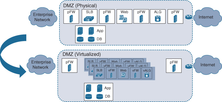
Virtualizing a traditional DMZ architecture offers the advantage of being able to deploy security network functions at a finer granularity, possibly for groups of like applications. The virtualized network functions are applied to a traffic flow based on its requirements. For example, traffic between a trusted partner and your enterprise applications may not require the same level of protection (i.e., the same security functions and rules) as connectivity between your engineering department and the Internet. Security VNFs are applied in the DMZ more dynamically, based on the source and destination relationship of the traffic. Also, network functions are deployed as needed, following a usage-based consumption model. If you establish a new relationship to a partner organization, the applicable security VNFs can be instantiated if and when needed. In contrast, in a hardware appliance–based environment, you have to plan for such relationships long term to ensure that sufficient infrastructure resources are available also for future growth in terms of partners or traffic. Virtualization in this context thus again enables a dynamic consumption model, where costs are incurred if and when needed (operational expenditures, or OPEX), rather than built out with anticipated capacity (capital expenditures, or CAPEX). The architectural shift from hardware-based appliances to VNFs is illustrated in Figure 18-29.
The consumer and provider landscape also becomes increasingly more dynamic. More and more applications are hosted in hybrid cloud environments, in virtual-private cloud infrastructures managed by your own networking department (e.g., Amazon AWS, Google GPC, Microsoft Azure), consumed as a service (e.g., Microsoft Office 365, Salesforce), or even in your own private cloud environments to meet regional or regulatory requirements. Similarly, the number of consumers becomes increasingly more sophisticated: digitalized business processes foster easier relationships with partner organizations. The number of partners wishing to interact with your applications grows steadily. Employees are also no longer restricted to work in an office environment, but are increasingly connecting from home or from the road. Both of these trends imply that traffic patterns are becoming increasingly fluid and dynamic—the old traffic patterns of all traffic being directed to your data centers is breaking up. These trends lead to the discussions on where to architect connectivity to external domains. The two principal options are
Direct Internet access (DIA)/direct cloud access (DCA) from the branch
A set of more centralized breakout points, possibly hosted by a carrier-neutral facility (CNF) provider
DIA/DCA in the branch requires a security perimeter to be established in every branch. This is an attractive option from an architectural perspective for a smaller number of branch locations and if the security functions can be highly automated. For example, assuming that x86-based compute resources are available, a virtual firewall can be automatically deployed in each branch, and governed with a standardized set of firewall rules to regulate and protect traffic to and from untrusted domains. This is the ENFV use case described in the previous section.
A more centralized approach (not necessarily fully centralized in a single location!) is often more cost effective for larger numbers of branches and as the network functions that need to be applied to the consumer–provider relationships varies. In this case, connecting several branches to a more central facility using an enterprise WAN, grouping consumers and providers from a policy perspective, and then applying virtualized security functions in a service chain becomes more attractive.
Branches are connected to such a facility using traditional WAN mechanisms (such as MPLS VPN) or even Internet-based mechanisms (software-defined WAN [SD-WAN]). The decision whether to centralize or distribute a network function is often determined by an enterprise architecture cost analysis. Centralizing functions may allow you to use more efficient transport mechanisms. For example, connecting to a cloud provider using a high-quality direct link (e.g., Amazon AWS Direct Connect or Microsoft Azure ExpressRoute) may be economically attractive from a few centralized locations, but becomes overly costly for a large number of branches. In some cases, compute and networking resources are utilized more efficiently in a more centralized location serving multiple branches, rather than distributing those resources and underutilizing them in each.
Grouping of consumers and providers by similar characteristics reduces the variability in the policies to be applied. Without such groupings, the number of possible relationships between application consumers and application providers grows exponentially (the n2 problem).
Carrier-neutral facilities (co-location) can be leveraged to host these functions to further save on costs. CNFs offer a marketplace where multiple service providers, cloud providers, and enterprises are present and can “meet.” This gives you additional benefits from an enterprise network architecture perspective:
Your architecture becomes independent of the SP WAN provider. Any of the SPs present at the co-location facility can be leveraged to connect branches to your cage in the CoLo. You can choose an architecture with multiple WAN providers for redundancy, or more easily switch between providers when the WAN services no longer meet your requirements from a technical or cost perspective.
Your architecture also becomes independent of the cloud provider. As multiple cloud providers connect to the CoLo facility, your architecture is no longer tied to host applications with a single provider. This becomes increasingly important for hybrid cloud environments, where some applications may reside in your own data centers, other are hosted in VPCs, and yet others are consumed as a service. Again, if a particular cloud provider no longer meets your business requirements, you can more easily switch to another provider without significant changes to your enterprise architecture.
Figure 18-30 illustrates the co-location/CNF aspects of the Cisco SAE solution, highlighting the increasing number of connections to untrusted domains and cloud providers. Note that enterprise applications may still remain in parts in your own data centers.
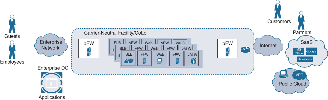
The Cisco SAE solution thus offers much more than just virtualizing a DMZ. The benefits and changes with virtualization and service chaining applied to dynamic consumer–provider relationships in centralized co-location facilities constitute a novel architectural approach. Cisco SAE allows your enterprise to be future-proof and ready for a network architecture supporting digitalized business processes.
Cisco SAE Building Blocks
Let’ s examine Cisco SAE from an architectural building block perspective. As previously indicated, the concepts of virtualizing network functions and chaining them also applies to this use case. The main differences between virtualizing connectivity to untrusted domains centrally and virtualization in branches are severalfold:
Scale: In SAE, due to the anticipated large number of dynamic consumer–provider relationships, the number of service chains in the architecture is larger. The Cisco ENFV solution accommodates a small number of VNFs and, consequently, service chains anchored against physical LAN and WAN interfaces. In the more centralized Cisco SAE solution, multiple service chains are instantiated to be applied to consumer–provider traffic flows anchored against logical interfaces, and even based on the desired business policies.
Types of VNFs: Due to the nature of Cisco SAE providing connectivity to external, untrusted domains, service chaining focuses on security VNFs. Virtual firewalls, IPS/IDS, deep packet inspection (DPI), antimalware, antivirus, and data-loss prevention functions become standard components in SAE service chains.
Service chain dynamics: In Cisco SAE, service chains are expected to be created and removed based on the consumer–provider relationships. These may change more often than in a branch environment as new partners and cloud providers are added, or as applications are moved from enterprise-operated data centers to single-cloud or multicloud environments.
From an architectural building block perspective, there are thus strong synergies between Cisco ENFV and Cisco SAE. The same four-layer architecture previously introduced also applies. Standard x86-based hosts provide the hardware resources to run virtualized network functions. The Cisco NFVIS operating system provides an optimized Linux-based environment to deploy and operate the VNFs, offering support for plug-and-play, local management and operations, lifecycle management, and open APIs. The VNF layer in case of Cisco SAE focuses on (but is not restricted to) virtualized security functions. Third-party VNFs are also supported. And the automation and orchestration functions in Cisco SAE support the dynamic nature of the use case and simplify ongoing operations of the solution.
To accommodate the scale requirements expected for a more centralized virtualization solution, hardware platforms with a larger number of cores than available in the Cisco ENCS are recommended in Cisco SAE. The Cisco Cloud Services Platform (CSP) 2100 offers an NFVIS-based appliance akin to the Cisco ENCS for this purpose. Both 1 RU (rack unit) and 2 RU versions are available offering up to 44 cores per chassis, and up to 768 GB of RAM—a lot of horsepower to run VNFs! More details on the Cisco CSP 2100 are provided in its data sheet.15
15 https://www.cisco.com/c/en/us/products/collateral/switches/cloud-services-platform-2100/datasheet-c78-735317.html
Running Virtualized Applications and VNFs Inside IOS XE
The solutions already described to virtualize network functions are based on the Cisco NFVIS operating system as described earlier in this chapter. An alternative hosting environment also exists within IOS XE for limited hosting of applications or VNFs. The IOS XE software architecture is actually based on a Linux environment, as depicted in Figure 18-31. All of the IOS XE–based hardware platforms are equipped with a multicore x86 processor that is first and foremost used to execute the IOS XE control plane. With IOS XE–based virtualization, the same Linux environment can be leveraged to also run containerized applications or even VNFs. Both KVM and Linux Containers (LXC) are supported.
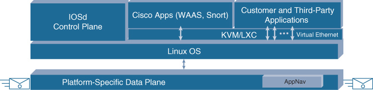
The number of physical CPU cores available on the ISR 4000 Series router or the ASR 1000 Series routers, for example, are sufficient to run lightweight applications or VNFs. The typical use cases fall into four main categories:
Troubleshooting: Deploy a virtual machine inside IOS XE to run customized troubleshooting tools. Examples are Wireshark and Speedtest applications.
Supporting network applications: The IOS XE virtualization capability is leveraged to run file servers, print servers, domain controllers, or similar applications.
Analytics: Virtualized network analysis and application performance monitoring functions are also hosted within an IOS XE–based network element. For example, the IPERF tool falls into this category.
Device customization: The standard LXC and KVM environments can be used in any generic manner to augment the capabilities of the host platform. Customizations such as the deployment of custom encryption functions or business policy–based routing could be provided by your network operations team or a partner.
The physical resource requirements for IOS XE–based virtualization again pertain to CPU cores, memory, and storage. On the ISR 4000 Series routers, up to three cores with varying clock speeds (depending on the model) are available for containers. Any containerized application of VNF that fits this profile can thus be instantiated directly on top of the IOS XE Linux OS. For a fully virtualized branch this may not be sufficient, in which case the Cisco ENFV solution may be more appropriate. But for the lightweight use cases summarized, IOS XE–based virtualization provides additional flexibility without dispatching new hardware into your branches.
To accommodate the additional containerized applications or VNFs, additional memory and storage has to be available in the IOS XE–based platforms. A minimum of 4 GB of additional dynamic RAM (DRAM), 50 GB of solid-state drive space, and 1 TB of hard disk drive space are required for this capability. Table 18-4 lists the available physical CPU cores for the ISR 4000 Series router platforms, as well as the additional (on top of IOS XE itself) memory and storage requirements.
Table 18-4 Cisco ISR 4000 Series Compute Resources for IOS XE Virtualization
Platform |
Service Cores |
Speed (GHz) |
Min Additional DRAM |
Min Additional SSD |
Min Additional HHD |
ISR4451 |
3 |
2 |
4GB |
200GB |
1TB |
ISR4431 |
3 |
1 |
4GB |
200GB |
1TB |
ISR4351 |
3 |
2.4 |
4GB |
50GB |
1TB |
ISR4331 |
3 |
2.0 |
4GB |
50GB |
1TB |
ISR4321 |
1 |
2.4 |
4GB |
50GB |
1TB |
The capabilities of the containerized applications or VNFs are expected to be described in a Yet Another Markup Language (YAML) descriptor file. This file specifies how many virtual CPUs (vCPU) and CPU cycle shares are required, how much memory and disk space needs to be reserved, as well as the virtual NIC descriptions or console and AUX port connectivity.
The actual container or VNF must be provided in one or more disk image files of type ISO, RAW, or QEMU Copy On Write (QCOW2). ISO disk image files are appropriate for read-only file systems such as a CD-ROM. RAW image files are supported for read and write file systems. QCOW2 image files are applicable for read and write file systems with compression. In the latter case, the file sizes may be significantly smaller at the expense of longer install times.
A manifest file and a version file in simple text format provide, respectively, the SHA1 hash for all files in the Open Virtual Appliance (OVA) and the application’s version number.
Containerized applications and VNFs are instantiated within IOS XE by use of the virtual-service commands. For example, the command
virtual-service install name testapp package bootflash:testapp.ova
installs a container called testapp provided in the OVA file testapp.ova. To enable packets to be directed to the container, a virtual port group with its associated IP address must be configured in the device’s IOS XE configuration. This allows the IOS XE data plane to direct traffic destined to the container app’s IP address, as illustrated in Figure 18-32. The creation of the virtual port group also activates the virtual switching capabilities via OVS at the Linux level, thus allowing connectivity between the IOS XE data plane and the application container or VNF.
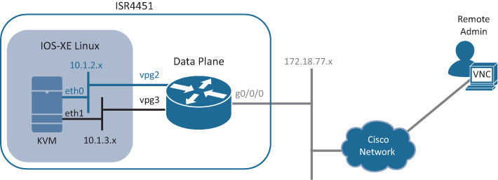
Details on how to configure application containers in IOS XE are available from Cisco.com.16
16 https://www.cisco.com/c/en/us/td/docs/switches/lan/catalyst3850/software/release/37e/b-openflow-37e-3850-and-3650/b-openflow-37e-3850_chapter_010.pdf
Summary
Virtualization of enterprise branch environments is one of the key initial use cases for NFV. The Cisco Enterprise NFV solution allows you to collapse multiple L4–L7 networking appliances into an x86-based hosting system without loss of functionality. This promises to reduce the complexity both from an architectural perspective and from an operational perspective of your branch environments. The following are some major points covered in this chapter:
The Cisco ENFV solution consists of four main building blocks. Various different hardware models give you the flexibility of selecting the appropriate x86-based hardware resources for your branch environment.
Cisco Network Functions Virtualization (NFVIS) offers the required hypervisor and virtualization OS with additional advantages. NFVIS also retains the flexibility and openness of the underlying Linux OS.
From a VNF perspective, the Cisco ENFV solution leverages both Cisco VNFs and support for third-party VNFs. Most Cisco VNFs are functionally equivalent to their hardware-based siblings, allowing you to embark on the journey of virtualization without fearing a loss of functionality. The Cisco ENFV solution allows you to run third-party VNFs or application workloads as long as they match the underlying NFVIS (Linux) requirements.
Cisco ENFV offers a centralized toolset embedded in the Cisco DNA Center solution. Any NFVIS system can also be managed using a local GUI. For the die-hard operators among you, using traditional mechanisms such as CLI, syslog, or MIBs is an option.
This chapter also discussed how the ENFV solution is extended to cover the use case of virtualizing connectivity from your enterprise network to untrusted and multicloud domains. All the preceding building blocks are carried forward in the Cisco SAE solution, but with additional scalability required to host many service chains, and with a particular focus on security VNFs.
For modest virtualization requirements, the chapter also reviewed the capabilities that exist within Cisco IOS XE. Any Cisco IOS XE–based hardware platform leverages x86 processors to execute the control plane functions. With today’s multicore x86 CPUs, a limited number of cores remain available in the IOS XE–based switches and routers to also run limited application workloads or even additional network functions not covered by IOS XE.
Further Reading
Cisco UCS E-Series Data Sheets, https://www.cisco.com/c/en/us/products/servers-unified-computing/ucs-e-series-servers/datasheet-listing.html
Cisco Enterprise Whitepaper, https://www.cisco.com/c/en/us/solutions/collateral/enterprise-networks/enterprise-network-functions-virtualization-nfv/white-paper-c11-736783.pdf