
Yard & Garden Projects

Outdoor carpentry projects are not limited to patio tables and garden benches. The projects in this chapter share a common theme: their main purpose is to improve the appearance of your yard.
Yards and gardens do not take care of themselves. So several projects in this chapter are designed to make yard and garden maintenance easier: a clever potting bench with work surfaces at two levels (because potted plants are not one-size-fits-all), a cold frame and more.
There are designs and instructions for several planters and containers: a triple-threat trellis planter for potting, climbing, and hanging; a planter based on a design from the Gardens at Versailles. And for pure decorative fun, we’ve included a wishing well/pump house with recirculating water, and a Japanese-inspired luminary.
In this chapter:
 Compost Bin
Composting yard debris is an increasingly popular practice that makes good environmental sense. Composting is the process of converting organic waste into rich fertilizer for the soil, usually in a compost bin. A well-designed compost bin has a few key features. It’s big enough to contain the organic material as it decomposes. It allows cross-flow of air to speed the process. And the bin area is easy to reach whether you’re adding waste, turning the compost, or removing the composted material. This compost bin has all these features, plus one additional benefit not shared by most compost bins: it’s very attractive.
Grass clippings, leaves, weeds, and vegetable waste are some of the most commonly composted materials. Just about any formerly living organic material can be composted, but do not add any of the following items to your compost bin:
• animal material or waste
• dairy products
• papers with colored inks
• baked goods
• branches or other pieces of wood
For more infromation on composting, contact your local libray or agricultural extension office.

Convert organic waste into garden fertilizer inside the confines of this easy-to-make cedar compost bin.
 Compost Bin
BUILD THE PANELS
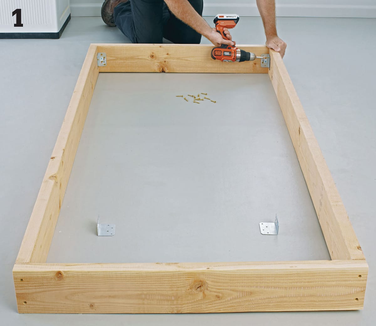
The four fence-type panels that make up the sides of this compost bin are cedar slats that attach to panel frames. The panel frames for the front and back of the bin are longer than the frames for the sides. Cut the side rails, end rails, and cleats to length. Group pairs of matching rails with a pair of cleats. Assemble each group into a frame—the cleats should be between the rails, flush with the ends. Drill 1/8"-diameter pilot holes into the rails. Counterbore the holes 1/4" deep using a counterbore bit. Fasten all four panel frames together by driving 3" deck screws through the rails and into each end of each cleat (photo 1).

Fasten the cleats between the rails to construct the panel frames.
Cut all of the slats to length. Lay the frames on a flat surface and place a slat at each end of each frame. Keep the edges of these outer slats flush with the outside edges of the frame and let the bottoms of the slats overhang the bottom frame rail by 4". Drill pilot holes in the slats. Counterbore the holes slightly. Fasten the outer slats to the frames with 11/2" deck screws (photo 2).

Attach a slat at each end of the panel frame so the outer edges of the slats are flush with the outer edges of the frame.
When you have fastened the outer slats to all of the frames, add slats between each pair of outer slats to fill out the panels. Insert a 11/2" spacing block between the slats to set the correct gap. This will allow air to flow into the bin. Be sure to keep the ends of the slats aligned. Check with a tape measure to make sure the bottoms of all the slats are 4" below the bottom of the panel frame (photo 3).

Continue to attach slats. The inner slats should be 11/2" apart, with the ends 4" below the bottom of the frame.
ATTACH THE PANELS & POSTS
The four slatted panels are joined with corner posts to make the bin. Three of the panels are attached permanently to the posts, while one of the end panels is installed with hinges and a latch so it can swing open like a gate. You can use plain 4 × 4 cedar posts for the corner posts. For a more decorative look, buy prefabricated fence posts or deck rail posts with carving or contours at the top.
Cut the posts to length. If you’re using plain posts, you may want to do some decorative contouring at one end or attach post caps. Stand a post upright on a flat work surface. Set one of the longer slatted panels next to the post, resting on the bottoms of the slats. Hold or clamp the panel to the post, with the back of the panel frame flush with the inside face of the post. Fasten the panel to the post by driving 3" deck screws through the frame cleats and into the posts. Space screws at roughly 8" intervals.
Stand another post on end, and fasten the other end of the panel frame to it, making sure the posts are aligned. Fasten one of the shorter panels to the adjoining face of one of the posts. The back faces of the frames should meet at the inside corner of the post (photo 4). Fasten another post at the free end of the shorter panel. Fasten the other longer panel to the posts so it is opposite the first longer panel, forming a U-shaped structure.

Stand the posts and panels upright, and fasten the panels to the posts by driving screws through the cleats.
ATTACH THE GATE
The unattached shorter panel is attached at the open end of the bin with hinges to create a swinging gate for loading and unloading material. Exterior wood stain or a clear wood sealer with UV protectant will keep the cedar from turning gray. If you are planning to apply a finish, it’s easier to apply it before you hang the gate. Make sure all hardware is rated for exterior use.
Set the last panel between the posts at the open end of the bin. Move the sides of the bin slightly, if needed, so there is about 1/4" of clearance between each end of the panel and the posts. Remove this panel gate and attach a pair of 3" butt hinges to a cleat, making sure the barrels of the hinges extend past the face of the outer slats. Set the panel into the opening, and mark the location of the hinge plates onto the post. Open the hinge so it is flat, and attach it to the post (photo 5). Attach a hook-and-eye latch to the unhinged end of the panel to hold the gate closed.

Attach exterior-rated hinges to the end panel frame and then fasten them to the post. Add a latch on the other side of the hinged panel.
Freestanding Arbor
This freestanding arbor combines the beauty and durability of natural cedar with an Asian-inspired design. Set it up on your patio or deck or in a quiet corner of your backyard. It adds just the right finishing touch to turn your outdoor living space into a showplace geared for relaxation and quiet contemplation.
The arbor has a long history as a focal point in gardens and other outdoor areas throughout the world. And if privacy and shade are concerns, you can enhance the sheltering quality by adding climbing vines that weave their way in and out of the trellis. Or, simply set a few potted plants around the base to help the arbor blend in with the outdoor environment. Another way to integrate plant life into your arbor is to hang decorative potted plants from the top beams.
This arbor is freestanding, so it can be easily moved to a new site whenever you desire. Or, you can anchor it permanently to a deck or to the ground and equip it with a built-in seat.
Sturdy posts made from 2 × 4 cedar serve as the base of the arbor, forming a framework for a 1 × 2 trellis system that scales the sides and top. The curved cutouts that give the arbor its Asian appeal are made with a jigsaw, then smoothed out with a drill and drum sander for a more finished appearance.

Create a shady retreat on a sunny patio or deck with this striking cedar arbor. It can also support a wealth of climbing plants if you so choose.
Freestanding Arbor
MAKE THE LEGS
Each of the four arbor legs is made from two 6-foot-long pieces of 2 × 4 cedar fastened at right angles with 3" deck screws. Cut the leg fronts and leg sides to length.
Position the leg sides at right angles to the leg fronts, with top and bottom edges flush. Apply moisture-resistant glue to the joint. Attach the leg fronts to the leg sides by driving evenly spaced screws through the faces of the fronts and into the edges of the sides (photo 1). Use a jigsaw to cut a 31/2"-long × 2"-wide notch at the top outside corner of each leg front (photo 2). These notches cradle the crossbeams when the arbor is assembled.

Create four legs by fastening leg sides to leg fronts at right angles.

Cut a 2 × 4-size notch in the top of each of the four leg pairs to hold the crossbeams.
MAKE THE CROSSBEAMS, RAILS & SPREADERS
Cut the crossbeams to length and then cut a small arc at both ends of each part. Start by using a compass to draw a 31/2"-diameter semicircle at the edge of a strip of cardboard. Cut out the semicircle, and use the strip as a template for marking the arcs (photo 3). Cut out the arcs with a jigsaw. Sand the cuts smooth with a drill and drum sander.

Lay out profiles on the ends of the crossbeams. A piece of cardboard acts as a template when you trace the outline for the arc.
Cut two side spreaders to length. The side spreaders fit just above the side rails on each side. Mark a curved cutting line on the bottom of each spreader. To mark the cutting lines, draw starting points 31/2" in from each end of a spreader. Make a reference line 2" up from the bottom of the spreader board. Tack a casing nail on the reference line, centered between the ends of the spreader. With the spreader clamped to the work surface, also tack nails into the work surface next to the starting lines on the spreader. Slip a thin strip of metal or plastic between the casing nails so the strip bows out to create a smooth arc. Trace the arc onto the spreader, then cut along the line with a jigsaw. Smooth with a drum sander. Use the first spreader as a template for marking and cutting the second spreader. Cut the side rails to length. They are fitted between pairs of legs on each side of the arbor, near the bottom, to keep the arbor square.
ASSEMBLE THE SIDE FRAMES
Each side frame consists of a front and back leg joined together by a side rail, a side spreader, and a crossbeam. Lay two leg assemblies parallel on a work surface, with the notched board in each leg facing up. Space the legs so the inside faces of the notched boards are 21" apart. Set a crossbeam into the notches, overhanging each leg by 6". Also set a side spreader and a side rail between the legs for spacing.
Drill 3/8"-diameter pilot holes in the crossbeam. Counterbore the holes to 1/4" depth using a counterbore bit. Attach the crossbeam to each leg with glue. Drive two 3/8"-diameter × 21/2" lag screws through the crossbeam and into the legs (photo 4). Position the side spreader between the legs so the top is 291/2" up from the bottoms of the legs. Position the side rail 18" up from the leg bottoms. Drill 1/8" countersunk pilot holes into the spreader and rail through the leg faces. Keeping the legs parallel, attach the pieces with glue and drive 3" deck screws through the outside faces of the legs and into the side rails and spreaders.

Lag-screw the crossbeams to the legs, and fasten the spreaders and rails with deck screws to assemble the side frames.
ATTACH THE SIDE TRELLIS PIECES
Each side trellis is made from vertical strips of cedar 1 × 2 that are fastened to the side frames. Horizontal cross strips will be added later to create a decorative cross-hatching effect. Cut three vertical trellis strips to length for each side frame. Space them so they are 23/8" apart, with the ends flush with the top of the crossbeam (photo 5).

Attach trellis strips to the crossbrace and spreader with deck screws.
Drill pilot holes to attach the trellis strips to the crossbeam and spreader. Countersink the holes and drive 21/2" deck screws. Repeat the procedure for the other side frame.
CUT & SHAPE TOP BEAMS
Cut two top beams to length. Draw 11/2"-deep arcs at the top edges of the top beams, starting at the ends of each of the boards. Cut the arcs into the top beams with a jigsaw. Sand smooth—use a drum sander, if you have one.
ASSEMBLE TOP & SIDES
Because the side frames are fairly heavy and bulky, you will need to brace them in an upright position to fasten the top beams between them. A simple way to do this is to use a pair of 1 × 4 braces to connect the tops and bottoms of the side frames (photo 6). Clamp the ends of the braces to the side frames so the side frames are 4 feet apart, and use a level to make sure the side frames are plumb.

Brace the side frames in an upright, level position with long pieces of 1 × 4 while you attach the top beams.
Mark a centerpoint for a lag bolt 123/4" from each end of each top beam. Drill a 1/4"-diameter counterbored pilot hole through the top edge at the centerpoint. Set the top beams on top of the crossbraces of the side frames. Mark the pilot hole locations onto the crossbeams. Remove the top beams and drill pilot holes into the crossbeams. Secure the top beams to the crossbeams with 6" lag screws.
Cut four braces to length, and transfer the brace cutout pattern from the diagram shown here to each board. Cut the patterns with a jigsaw. Attach the braces at the joints where the leg fronts meet the top beams, using 21/2" deck screws. To make sure the arbor assembly stays in position while you complete the project, attach 1 × 2 scraps between the front legs and between the back legs (photo 7). Cut and attach three trellis strips between the top beams.

Lock the legs in a square position after assembling the arbor by tacking strips of wood between the front legs and between the back legs.
ADD TRELLIS CROSS STRIPS
Cut the cross strips to 7" and 10" lengths. Use wood screws to attach them at 3" intervals in a staggered pattern on the side trellis pieces. You can adjust the sizes and placement of the cross strips but, for best appearance, retain some symmetry of placement. Fasten cross strips to the top trellis in the same manner. Make sure the cross strips that fit across the top trellis are arranged in similar fashion to the side strips (photo 8).

Attach the trellis cross strips to spice up the design and assist climbing plants.
APPLY FINISHING TOUCHES
To protect the arbor, coat the cedar wood with clear wood sealer. After the finish dries, the arbor is ready to be placed onto your deck or patio or in a quiet corner of your yard. Because of its sturdy construction, the arbor can simply be set onto a hard, flat surface. If you plan to install a permanent seat in the arbor, you should anchor it to the ground. For decks, try to position the arbor so you can screw the legs to the rim of the deck or toenail the legs into the deck boards. You can buy fabricated metal post stakes, available at most building centers, to use when anchoring the arbor to the ground.
High-low Potting Bench
Working the soil is part of the fun of gardening, but crouching down all day can be exhausting. Many gardening tasks are easier if you can work at a standard workbench height instead of on the ground. That’s where a potting bench comes in handy. A potting bench provides a comfortable and efficient place to work on gardening jobs that don’t have to happen on the ground.
What makes this potting bench different from most other potting benches is that the work surfaces are at appropriate heights for gardening tasks. The work surface is 30" high, making it easier to reach down into pots. The low work surface is just over a foot high, so you won’t have to lift heavy objects such as large pots or bags of soil. In addition to the high-low work surfaces, this bench also features a shelf and hook rail to keep small supplies and tools within reach, yet still off the main work area.
A potting bench gets wet and it gets dirty, so rot- and moisture-resistant materials were chosen to build this bench. The frame is made with pressure-treated pine lumber and the work surfaces are composite deck boards. The composite material provides a smooth surface that will not splinter and is easy to clean.

Not all pots are the same height. With two different working heights, this bench is comfortable to use whether you’re planting seeds in starter trays or planting a 5-gallon planter with tomatoes.
High-low Potting Bench
CUT THE FRAME PARTS
Cut all of the frame and shelf parts to length. Draw a 31/2" radius on the front bottom corner of each shelf support. Cut along the radius lines with a jigsaw or bandsaw (photo 1). Sand the profiles smooth.

Cut the shelf supports. Use a bandsaw or a jigsaw to make the 31/2" radius roundovers on the ends of the shelf supports. Sand smooth.
Apply a solid color exterior deck and siding stain to all sides of the frame and shelf parts. Staining these parts isn’t mandatory, but it’s an opportunity to customize your workbench and the stain will extend the life of the parts.
ASSEMBLE THE FRAME
Attach two back rails and one bottom rail to the long leg, back strut, and back right mid-length leg with 2" deck screws. Check that all of the parts intersect at 90-degree angles. Attach the front rail and one bottom rail to the left front mid-length leg, front strut, and short leg. Connect the back assembly and front assembly by attaching them to the cross supports (photo 2).

Assemble the bench frame. Clamp the cross supports to the front and back assemblies. Attach the cross supports with 2" deck screws.
ATTACH THE WORKTOP PLANKS
Cut the deck boards that will be used to create the work surfaces to length. We used composite deck boards because they require little maintenance and are easy to clean. (See here for more information on working with composites). Place the front deck board for the lower work surface against the backside of the front left leg and front strut. Mark the point where the front leg and strut intersect the deck board. Using these marks, draw the 33/4" deep notch outlines and cut out the notches with a jigsaw (photo 3).

Cut notches. Lay out notches in the front board for the low work surface where the board must fit around the front leg and front strut. Use a jigsaw to cut the notches.
Place the top and bottom deck boards on the cross supports, leaving a 1/4" space between the boards. Drill two pilot holes that are centered over the cross supports in each deck board. Attach the deck boards with 2" deck screws (photo 4). If you are using composite deck boards, use specially designed decking screws.

Install the worktop slats. Use composite screws to attach the composite deck boards that create the upper and lower worktops.
ATTACH THE SHELF & RACK
Attach the shelf back, shelf hook rail, and shelf supports to the long leg and back strut with 21/2" deck screws. Attach the shelf to the shelf supports with 2" deck screws. Fasten the hooks to the shelf hook rail (photo 5).

Install the shelf and hook rail. Attach the shelf to the shelf supports. Drill pilot holes for each screw to prevent splitting the shelf supports. Once the hook rail is installed twist in the cup hooks.
Trellis Planter
You don’t need a large yard—or any yard at all for that matter—to have a garden. Planting in containers makes it possible to cultivate a garden just about anywhere. A container garden can be as simple as a small flowering annual planted in a single 4" pot or as elaborate as a variety of shrubs, flowering plants, and ornamental grasses planted in a large stationary planter.
This planter project combines a couple of different container options to create a larger garden in a relatively small space. The base is an 18 × 30" planter box that is large enough to hold several small plants, a couple of medium-sized plants, or one large plant. It features a trellis back that can be covered by climbing plants.
In addition to the planter and trellis, this project features two plant hangers that extend out from the back posts. Adding a couple of hanging plant baskets further extends the garden display without increasing the space taken up by the planter.
This project is easiest to build with a table saw, miter saw, jigsaw, and drill/driver. If you don’t have access to a table saw, use a circular saw or jigsaw and straightedge to rip the 1 × 6 siding boards. An even easier option is to replace the 23/4"-wide siding boards with 31/2"-wide 1 × 4s. This modification makes the planter 41/2" taller, so you also have to make the front posts 241/2" long instead of 20" long and add 41/2" to the length of the front posts trim.

This efficient planter combines a box for container gardening with a climbing trellis and a pair of profiled arms for hanging potted plants.
Trellis Planter
CUT THE BASE PARTS
Cutting the front posts (2 × 4) and back posts (4 × 4) to length is easy. Cutting the hanger parts is a bit trickier, primarily because the plant hangers splay out from the corners of the posts at a 45° angle. The top, outside post corners must be beveled to create flat mounting surface for the hangers. Mark the bevel cut lines on the outside and front faces of the posts (photo 1). Tilt the shoe of a jigsaw to 45° and bevel-cut along the layout lines (photo 2). Use a handsaw to make a stop cut that meets the bottom of the bevel cut in each back post, forming a shoulder (photo 3). Rip-cut some 1 × 6 stock to 23/4" wide (photo 4) using a table saw or a circular saw and a straightedge cutting guide. Cut six 30"-long pieces and twelve 211/2"-long pieces to make the siding strips.

Mark the post bevel cuts. The lines at the top of each back post should be drawn 1" out from the corner and should run down the post for 12" long.

Cut the bevels. Tilt the foot of a jigsaw at a 45° angle so it will ride smoothly on the post face and follow the bevel cutting line. Make a bevel cut along the layout line.

Make the shoulder cut. Use a handsaw to cut into the corner of the post to meet the bevel cut, creating a shoulder for the beveled corner.

Rip 1 × 6 stock for siding. Using a table saw or a circular saw and cutting guide, rip enough material for the sides and the front to 23/4".
Also use a circular saw or table saw to cut the bottom and back panels to length and width. Cut 11/2"-long × 31/2"-wide notches out of the front corners of the bottom panel. Cut the front post trim, bottom supports, and back climbing rails to length from 1 × 2 boards.
ASSEMBLE THE BASE PLANTER
Attach the front siding strips to the front posts with 2" exterior screws. Align the ends of the siding pieces flush with the sides of the front legs. Leave a 1/4" space between the siding boards. Drive one screw through each end of each siding board and into the front legs. Drill a countersunk pilot hole for each screw. Attach the front post trim pieces to the front posts with three or four 2" brad nails or finish nails. Align the front edge of the trim pieces flush with the front face of the front siding. Attach the back panel to the back posts with six 2" screws. Drive three screws into each post.
Attach the back lattice rails to the back posts. Drive one screw through each end of each climbing rail (photo 5). Refer to the construction drawing shown here for lattice spacing. Place the front and back assemblies on their sides and install siding on the side that’s facing up. The siding boards should be positioned against the front post trim board and flush with the back edge of the back post, spaced 1/4" apart. Attach the siding with 2" screws (photo 6). Flip the project over and repeat the process to attach siding to the other side.

Add the latticework. Attach the horizontal climbing rails to the back posts with countersunk 2" screws. Use one screw at each lattice connection to the posts.

Install siding. Attach the siding to the front and back posts with countersunk 2" screws. After completing one side, flip the project and complete the other side. Then, install siding strips on the front.
Attach the bottom supports to the front and back legs. The bottom of the front end of the bottom support should be flush with the bottom of the siding. The bottom of the back end of the bottom support should be positioned 2" up from the bottom of the back post. Drive one screw through the front end of the support and into the front leg and two screws into the back legs. Attach the bottom to the bottom supports with four 2" screws—two into each support.
BUILD THE PLANT HANGERS
Cut the hanger backs, hanger arms, and hanger braces to length. Draw the hanger arm profile onto the side of each hanger arm, and use a compass to draw the radius profiles. Profile details are shown on the construction drawings (shown here). Use a jigsaw to cut along the profile layout lines on the hanger arms. Both ends of the hanger brace are mitered at 45°, but the back or bottom end is a compound miter cut, meaning that it has both a miter and a bevel component. Cut the top end 45° miters on all four braces. Then, make compound cuts at the bottom ends of the hanger braces (photo 7). Make the cuts so the beveled end faces the post when it is attached.

Cut the hanger brace angles. After cutting a flat 45° miter in the top end of the hanger brace, make a compound bevel/miter cut in the bottom end so it will fit flat against the bevel cut in the post.
Drill a 3/8"-diameter hole through the top of each hanger arm. Locate the hole 3" in from the end of the hanger arm. Fasten one eyebolt, two flat washers, and a locknut through each hanger arm. Attach the hanger back to the back end of the hanger arm with two 3" screws. Position a 2 × 2 hanger back and a 2 × 4 hanger arm against the beveled corner of each back post. Drive two 3" screws through the hanger back and into the back posts. Attach the hanger braces to the hanger back and hanger arm with 2" screws (photo 8). Make sure the hanger arms remain perpendicular to the posts when you attach the braces.

Install the hanger braces. Clamp the hanger braces to the hanger arms and hanger backs. Attach the hanger braces with 2" screws driven into the hanger back and into the hanger arm. Drive two countersunk screws at each connection.
FILL PLANTER
The planter itself is lined with heavy (at least 4-mil thick) black plastic sheeting. Cut the sheeting pieces that cover the sides, front, and bottom several inches oversized so they overlap in the corners. Cut the back sheeting the same size as the back panel. Attach the plastic to the inside faces of the planter with staples (photo 9). Start with the bottom sheet, overlap the sides on the bottom, and then overlap the front over the sides and bottom. Finally overlap the back over the sides, leaving a small gap between the bottom of the back sheet and the bottom sheet to allow water to drain out. Fill the planter with potting soil and add your plants. TIP: Adding a few inches of gravel to the bottom of the planting compartment allows for better drainage.

Line the container. Attach 4-mil black plastic liner with 3/8" stainless steel staples. Overlap the plastic in the corners and leave a small gap along the back bottom edge for drainage.
Raised Bed with Removable Trellis
It’s hard to beat PVC plumbing pipe for adding a trellis to a simple raised bed. It’s inexpensive and rot-proof and goes together like pieces of a toy construction set. It’s also durable, lightweight, and can stand up to just about anything the elements throw at it.
This all-purpose trellis is made almost entirely with PVC parts and is designed to be custom-fit to your raised bed. For a bed with 2× lumber sides, you can secure the trellis uprights to the outside of the bed with metal pipe straps. If the sides of the bed are built with timbers, the trellis simply drops into holes drilled into the tops of the timbers. Of course, you can get much more creative with the configuration if you want to bump up your yield. Add another, identical trellis to the opposite end of a longer raised bed. Or add three—at either end and in the middle—of a really long bed. Making the most of vertical space with a trellis is a great way to grow a lot more vegetables in the same footprint. This can be key if you’re looking to put up a lot of vegetables for over the winter.
The trellis as shown is made with 11/2-inch PVC pipe and fittings. The parts are friction fit only, so they are not glued together and can easily be disassembled for off-season storage. PVC pipe and fittings are manufactured for a very tight fit; if you push the pipe all the way into the fittings, the joints won’t come apart unless you want them to. Separate the joints by twisting the pipe or fitting while pulling straight out. Due to the tight fit, it doesn’t help to try to wiggle it loose.
PVC pipe and fittings come in one color: stark white. You may want to paint your trellis to blend in with your garden setting, but this isn’t necessary. Once it becomes covered with lush plant growth, the appearance of the pipe will be much less noticeable. Exposure to sunlight somewhat dulls PVC over time, but this doesn’t significantly affect its strength.

A raised bed box made from 2 × 6 lumber is used as the base for a sturdy built-in trellis made of PVC tubing. It’s the ideal support for heavy climbing plants like beans or cucumbers.
Raised Bed with Removable Trellis
Start by assembling the raised-bed box, reinforcing the joints with metal inside corners. Add a center divider to keep the sides from spreading apart if you decide to make this project longer than 6'. Even if it is shorter, the divider is still a good precaution to help prevent warping.

Cut 12"-long pieces of 11/2" PVC tubing. Attach them to the outsides of the planter box, near the middle. Use emery paper or sandpaper to remove the burrs and smooth the cut ends of pipe. Draw a perpendicular line where the pipe will go, using a square. Strap the pieces to the outsides with two pipe straps each. Fasten one strap with two screws, but leave the other strap loose until you put the upper vertical PVC on and can check it for plumb.

Add a T-fitting to the top end of each pipe. Measure between the hubs of the T-fittings to the insides of the sockets. Cut a piece of 11/2" PVC pipe to this length and sand the cut edges smooth; this is the bottom crosspiece. Remove both Ts, fit the piece into the middle hubs of the Ts so the ends of the pipe bottom out in the fittings. Then replace the Ts.

Add the uprights and attach the top crosspiece with elbows. Ensure the pipes are plumb, then secure the bottom straps. Move the planter into your yard or garden, line it with a thick layer of old newspaper or landscape fabric, and fill it with planting medium. Tie jute or hemp twine between the crosspieces so that climbing plants have something to grab onto. When winter comes, you can disassemble the PVC and store it away until spring.
TIP: Raised Box Trellis Options
The basic design of this bed-and-trellis combination lends itself to customization. If, for instance, you want a sturdier trellis to support much heavier plants or stand up to high winds, you can swap the PVC pipes and fittings for metal plumbing pipes and fittings. Better yet, if you want to add a rustic appeal to your unit, you can use copper pipes—just seal the copper so that it doesn’t contaminate your plants. The box itself can easily be fabricated from found lumber, or lumber reclaimed from construction sites (just ask the site supervisor or foreman before you go dumpster diving). The only requirement is that the wood you reuse not be treated in any way. Otherwise, free is the best price for a self-sufficient project!
Versailles Planter
Possibly the most famous gardens in the world, the gardens at King Louis XIV’s Versailles palace are the birthplace of this famous rolling planter style. Reportedly created by landscape architect Andre Le Notre, the Versailles Planter was originally designed to accommodate the many orange trees that were moved in and out of the orange groves on the grounds. The planter seen here differs in several ways from the classic Versailles model, but anyone who has a historical sense of gardening will recognize the archetypal form immediately.
The classic Versailles planter is constructed from oak slats and is bound together with cast iron straps. Cast iron ball or acorn finials atop the corner posts are also present on virtually every version of the planter. Most of the planters that existed (and still exist) on the Versailles grounds today are considerably larger than the one seen here, with sides as wide as 5 feet, and as tall as 7 feet. These larger models typically have hinged corners so the sides can be removed easily to plant the tree or shrub, as well as to provide care and maintenance. The X-shaped infill on the design seen here is present in some of the Versailles models, but many others consist of unadorned vertical slats.
At 24 × 24", this historical planter can be home to small- to medium-sized ornamental or specimen trees. The trees can be planted directly into the planter or in containers that are set inside the planter. If you wish to move the plants to follow sunlight or for seasonal protection, install the casters as they are shown. Otherwise, the casters can be left out.
Not a gardener? Try building a slatted top for the planter to create a rolling storage bin that, conveniently, is roughly the same height as a patio table. Or even make a few to serve multiple purposes around your yard while maintaining a consistent design theme.

Based on a classic design originated by the landscape architect for Louis XIV’s gardens at Versailles, this rolling planter can hold small fruit trees (its original purpose) or be put to use in any number of creative ways in your garden or yard.
Versailles Planter
MAKE THE BOX
Building the box for the Versailles Planter constitutes most of the work for this project. Start by cutting four 30"-long 4 × 4 cedar posts. Install a 1/4" piloted chamfering bit in your router and chamfer all four sides of each post top to create 45° bevels (photo 1). You may find that this is easier if you gang all four posts together edge-to-edge and then spin them each 90° after each cut.

Make the posts. After cutting them to length from 4 × 4 cedar, make a 1/4" chamfer cut around all the tops. Gang the posts together for profiling if you like.
Cut the 2 × 2 pressure-treated corner nailers to length and attach them to the inside faces of the posts so the nailers meet at the inside corners. The bottoms of the nailers should be 4" above the post bottoms and the tops should be 3" down from the post tops. Use exterior adhesive and 3" deck screws to attach the nailers.
Prepare a 2 × 4 for the top rails and a 2 × 6 for the bottom rails by cutting a rabbet into each work piece (photo 2). Located on the bottom inside edge of the 2 × 4 and the top inside edge of the 2 × 6, the rabbets should be 3/4" wide × 3/4" deep. You can cut them with a table saw or a router. After cutting the rabbets, cut the rails to length. Lay out the profile on the bottom rails and cut with a jigsaw. Sand smooth.

Cut panel rabbets. Make the 3/4 × 3/4" rabbet cuts in the rail stock using a table saw or router. The rabbets will accept the plywood side panels.
Cut the side panels from 3/4" exterior plywood. Create four side assemblies by attaching the panels in the rabbets on pairs of mating top and bottom rails. Use adhesive and 11/4" deck screws driven through the plywood and into the rails.
Attach the side assemblies to the 2 × 2 nailers on the inside faces of the posts. The top rails should all align 1" down from the post tops. Use adhesive and 3" deck screws driven through the nailers and into the rails. Also drive a few 11/4" deck screws through the panels and into the nailers, making sure to countersink the screwheads slightly so they can be concealed with wood putty (photo 3).

Attach the side assemblies. First, drive 3" deck screws through the corner nailers and into the rails. Then, drive 11/4" deck screws through the side panels and into the nailers. Reinforce the joints with construction adhesive.
Flip the box so it is top-down on your work surface and then install the 2 × 2 bottom braces and blocking. It will work best if you first create the brace grid by end-screwing through the four outer braces and into the inner braces and blocking. Then, attach the four outer braces to the bottom rails with adhesive and 3" deck screws driven every 4" or so (photo 4). Now, cut the bottom panel to size. Drill a 1" drain hole every 6" (resulting in nine drain holes). Cut 11/2" notches at the corners of the bottom panel using a jigsaw. Set the box with the top up and attach the bottom panel to the braces with adhesive and 11/4" deck screws.

Attach the bottom braces. Assemble the braces into a square grid using adhesive and screws and then attach the whole assembly to the base rails by screwing through the four outer braces that meet the rails.
ADD DECORATIVE TOUCHES
Rip-cut an 8-foot-long cedar 1 × 6 into two 2"- wide strips using a tablesaw or circular saw and straightedge guide. Cut the legs of the Xs to length. Cut off the corners of the full-length legs on a miter saw to create arrow shapes. Install the legs between opposite corners of the side panel on the outside faces using construction adhesive and a few 1" brass brads. Cut the half-length × legs with a square end and a pointed end and attach them to the side panels, completing the × shapes (photo 5).

Make the X shape. The distinctive × shape on the outer surfaces of the side panels is made with 2"-wide strips of cedar that are fastened with adhesive and 1" brass brads.
Turn the box back upside down and install 3" exterior-rated casters at the corners of the bottom panel. Flip it onto the casters and attach cedar post cap finials (acorn-shape or round) to the tops of the posts if you wish. Or, leave the tops unadorned. Apply two or three coats of exterior trim paint to the outside of the planter and to the inside at least 6" down from the top. If you will be placing dirt directly into the planter, line it with sheet plastic first. A better idea is to plant your tree or shrub in a square pot and set the pot into the planter. TIP: If you wish to use the planter form as a patio table, attach some cedar 1 × 4 slats to a pair of 17"-long 2 × 4 stretchers and set the top (called a duckboard) onto the planter.
Jumbo Cold Frame
A cold frame of any size works on the same principle as a greenhouse, capturing sunlight and heat while protecting plants from cold winds and frost. But when your planting needs outgrow a basic backyard cold frame with a windowsash roof, it makes sense to look to the greenhouse for more comprehensive design inspiration. This jumbo version offers over 17 square feet of planting area and combines the convenience of a cold frame with the full sun exposure of a greenhouse. Plus, there’s ample height under the cold frame’s canopy for growing taller plants.
The canopy pivots on hinges and can be propped all the way up or partially opened to several different positions for ventilating the interior to control temperature. The hinges can be separated just like door hinges (in fact, they are door hinges), so you can remove the canopy for the off season, if desired. Clear polycarbonate roofing panels make the canopy lightweight yet durable, while admitting up to 90 percent of the sun’s UV rays (depending on the panels you choose).
The base of the cold frame is a simple rectangle made with 2 × 6 lumber. You can pick it up and set it over an existing bed of plantings, or give it a permanent home, perhaps including a foundation of bricks or patio pavers to protect the wood from ground moisture. For additional frost protection and richer soil for your seedlings, dig down a foot or so inside the cold frame and work in a thick layer of mulch. Because all sides of the canopy have clear glazing, you don’t have to worry about orienting the cold frame toward the sun; as virtually all of the interior space is equally exposed to light.

A cold frame can extend the growing season in your garden to almost—or truly—year round. Use an oversized cold frame like the one in this project and there may be no need to put up vegetables in the fall, because you’ll have all the fresh produce you can handle. The hinged canopy is secured with eye hooks when closed to trap heat, but can be propped open for venting to prevent heat buildup.

Jumbo Cold Frame
BUILD THE BOXES
Making the boxes for this jumbo cold frame is the easiest part of the project. The full box frame is simply a rectangle formed from butt-jointed pieces of 2 × 6.
Cut these pieces to length and then drill pilot holes and fasten the frame end pieces between the frame side pieces with 3" deck screws. Use two screws for each joint. Then, cut the canopy frame pieces to length and join them in the same fashion (photo 1).

Assemble the box frames with simple butt joints. The base frame and the canopy frame are rectangles of the same dimensions.
Stabilize the corners of the canopy frame with 2 × 4 braces cut to 45° angles at both ends. Install the braces on-the-flat, so their top faces are flush with the tops of the canopy frame. Drill pilot holes and fasten through the braces and into the frame with one 21/2" screw at each end (photo 2). Then, drive one more screw through the outside of the frame and into each end of the brace. Check the frame for square as you work.

Install miter-cut 2x4 braces at each corner of the canopy frame to help prevent it from racking.
MAKE THE CANOPY SUPPORT
The roof (called the canopy here) for this jumbo cold frame is made of clear corrugated plastic roof panels. The clear end caps are made of inexpensive acrylic. These parts are attached to a support framework fashioned from 1/2"-diameter PVC tubing. Build your framework first and then custom-make the roof and end panels to ensure a good fit all around.
Cut all the frame ribs to 37" long from 1/2" PVC tubing (photo 3). You can cut these easily with a jigsaw, miter saw, hacksaw, or a tubing cutter (a specialty plumbing tool).

Cut the ribs for the canopy support framework from 1/2" PVC tubing. Make sure you’re using flexible PVC and not rigid Schedule 40 PVC.
Use the heads of 2" deck screws as receptors that you can fit the open ends of the tubing ribs onto. Drive the screws in 1" from the outside edges of the base frame and 3/4" from the ends, angling the screws at about a 35 to 45° angle toward the center (photo 4). Leave about 3/4" of the screw exposed. Drive two additional screws on opposite sides of the base frame, 321/4" from each end.

Deck screws driven partway into the top edges of the base frame are used as receptors over which the ribs are fitted.
Install the PVC ribs by sliding one end securely onto the angled 2" screw, then bending the tubing until the other end fits over the opposite screw (photo 5). Take your time with this, and use a helper if you need. The tension from the bent PVC should be sufficient to hold the ribs in place during assembly of the canopy, but you can wrap a little duct tape around them to hold them steady if they want to spring off of the screws.

Flex the PVC tubing to both ends fit over opposite screws. The tubing should snap back to create tension that holds it in place.
CUT THE END PANELS
The roof of the canopy is formed from corrugated plastic roof panels. These are relatively inexpensive and lightweight, which makes the cold frame portable. But they have enough structural integrity to stiffen up the canopy so there is no need to add ties or spreaders between the individual roof ribs.
When making the canopy, use your box frames and ribs to mechanically transfer the shapes and dimensions to the parts before you cut them. Start with the end panels, which can be cut from one 24 × 30" sheet of clear acrylic (sold in the size at most building centers). To mark the sheet for cutting, hold it against one end with the edge flat on the ground. Trace the curving top edge of the end PVC tubing rib onto the acrylic, using a marker (photo 6). Cut the clear acrylic along this cutting line with a jigsaw fitted with a plastic-cutting jigsaw blade or any fine-tooth jigsaw blade. Do not install the end panels yet.

Trace the profile of the end ribs onto a sheet of clear acrylic to create a cutting line for the end panels.
INSTALL THE CANOPY PANELS
The framework for the raised bed canopy is sized so a pair of 25 × 96" roof panels (a standard size) will span the framework with enough overlap at the top to create a good seam.
Start installing them by attaching the bottom edge of one of the panels to the outside edge of the base frame, about an inch up from the bottom. Drill 1/4" holes along the bottom edge of the panel. These guide holes for the screws need to be at least 1/2" down from the edge of the 2 × 3 so it will not split.
Locate the holes so they are 21/2" from each end. Drill additional holes in the same line, approximately every 16". Attach one panel along the bottom edge by driving a self-sealing roofing screw at each screw guide hole you’ve drilled (photo 7). Note: To ensure that the ribs on the corrugated panels overlap snugly at the seam, install one panel first, all the way to the top, and then install the second panel starting at the top and working your way down the opposite side from the first panel.

Secure the lower edge of one of the corrugated roofing panels to the base frame. Use self-sealing roofing screws (they have an EPDM rubber gasket).
Mark and drill 1/4" rib guide holes for the next course of screws into the roof panel, 4 to 6" up from the bottom. Locate holes for the ribs so they are 15/8" and 331/4" from each end (four ribs total). Adjust the PVC ribs until the predrilled holes in the roof panels are centered on the ribs, then predrill each rib through the outer wall with a 1/8" bit. Fasten the panel to the two intermediate ribs (photo 8).

Drive the next course of screws through guide holes in the panel and into pilot holes in the PVC ribs.
At the ends, insert a plastic closure strip (sold by the roof panel supplier) over the end ribs to fit between the rib and the roof panel and close the voids. Hold the closure strip securely in place and predrill it and the rib wall (photo 9). Attach the panel at each end and continue to secure it with screws, working toward the top.

Cut closure strips to fit at each end and then drive the screws to secure the ends of the panels. Screws should be driven only at troughs in the corrugated panels and should go through panel, closure strip, and rib wall at once.
At the top, lap the second panel over the first so the two panels fit together and make a clean seam. They should overlap so at least two of the panel ridges are covered with a double layer of roof panel. Position the second panel and trim it for width if necessary (it’s okay to overlap several ridges instead of cutting). Fasten the second panel using the same screw pattern you used on the first.
ATTACH THE END PANELS
Fit the arc-shaped end panels that you’ve already cut into the openings at the ends of the canopy. Mark the screw locations. Place the panel on a piece of plywood and predrill screw guide holes with a 1/4"-diameter bit to avoid cracking the clear acrylic, which isn’t as soft or flexible as the roof panels.
Screw the panels in place with self-sealing roofing screws, hand-tightening with a screwdriver to avoid overdriving them and cracking the clear acrylic (photo 10).

Attach the acrylic end panels to the canopy frame. Carefully drill guide holes in the acrylic sheeting before driving screws. Use a hand screwdriver to ensure that you do not overdrive the screws and crack the acrylic.
INSTALL THE CANOPY
Mount the completed canopy to the cold frame base using a pair of exterior hinges (31/2" galvanized butt hinges are shown here). The canopy frame should fit flush over the base on all sides (photo 11). Be sure to use exterior-rated screws.

Attach the canopy frame to the base frame with exterior-rated butt hinges.
Screw in two hook-and-eye latches in front so you can secure the canopy to help keep critters out and also to hold the canopy closed tightly if the wind should pick up.
ATTACH PROP STICKS
Attach a prop stick to each end of the cold frame, securing each prop with a stainless steel bolt and nut. Insert three washers (or more if necessary) between the prop stick and the 2 × 6 base so the prop stick clears the acrylic end panel. Drill additional 5/16" holes in the stick and the frame for the eyebolts, so that you can prop the canopy open at different heights (photo 12).

Attaching a propping stick with multiple height settings lets you vent the cold frame if it gets too hot inside or you want the plants to benefit from a nice rainfall.
Now, prepare the ground and place the cold frame in the desired location. Anchor the base to the ground using 16" treated wood stakes or heavy-duty metal angles driven into the ground and secured to the frame.
Pagoda Lantern
Enhance your landscape with this decorative pagoda lantern. It will act as an interesting focal point within your garden by day and its glow makes it even more inviting at night. It’s made from commonly available dimensional lumber—four pieces of 1 × 6 and one piece of 2 × 2. You can stain the wood to complement the surrounding landscape or you might choose to stain it or paint it to look like the Asian structures that inspired its design.
The stacked tiers of the pagoda are frames that are attached to four corner legs. Connecting four crosspieces with half-lap joints makes each frame. The top frame features similar construction to the sides and is capped with a square piece and a wood ball to create the peak. Any 2"-diameter wood ball (or even a copper ball) will work as the cap ball, but it should ideally be made from exterior-rated wood. You can also use a manufactured post cap for the cap plate and ball.
Candles illuminate this lantern. The candles are placed on a tile base and can be placed within a glass vase or hurricane lantern shade to prevent burning the wood structure.

Big enough to make a statement but compact enough to fit just about anywhere, this oak lantern can house large outdoor candles or even a low-voltage landscape light.
Pagoda Lantern
MAKE THE CROSSPIECES & TOP RAIL
If you do some careful planning and marking, the crosspieces can be cut from three 8-foot-long 1 × 6 boards. First, cut the boards to length. Cut one 1 × 6 into four 24" pieces. Then cut two 27" boards and two 21" boards from each of the other two 1 × 6s. Cut the 1 × 6 pieces in half lengthwise, leaving you with the twenty 21/4" wide crosspieces (photo 1).

Rip-cut the stock. On a table saw (if you have access to one), rip-cut each piece of 1 × 6 stock for the crosspieces into two equal strips that are approximately 21/4" wide.
Use a miter saw to trim the bottom corners (13/4 × 13/4") off each end of the crosspieces (photo 2). You can also use a table saw and miter gauge to make these cuts. The crosspieces fit together with half-lap joints in much the manner of toy building logs. The half-lap notches are 11/8" deep and equal to the thickness of the crosspieces (3/4 to 7/8"). To lay out the notches, mark the center of the middle and bottom crosspieces and then make a mark 71/2" on each side of the centerline to designate the inside edge of the notches. Mark the center of the top crosspieces and then make a mark 13/4" on each side of the centerline to designate the inside edge of the notches. Cut the notches in several crosspieces at the same time to save time and ensure consistent notch widths.

Trim the crosspiece corners. Set the miter saw to make a 45° cut and make each cut 13/4" from each end.
You must flip half of the crosspieces for each size upside-down so that you end up with an equal number of pieces with notch cuts on the top and on the bottom edge. You can use a table saw, router, or circular saw to cut the half-lap notches. Use a miter gauge to guide the pieces on a table saw, making several passes to cut the full width. Use a straight-edge to guide a circular saw or router (photo 3).

Cut half-lap notches. Clamp the crosspieces together with the notch cutout marks aligned. Use several passes with a router and straight bit to remove the waste material from the notches, lowering the bit 1/4" for each pass.
Mark the arc profile along the top edge of the four top crosspieces. Cut along the arc line with a jigsaw or band saw.
Cut 15"-long top rail pieces to length from 1 × 2 stock. Then, rip the four pieces down to 1" wide. Cut 45° miters in each end of the top rails. Mark the center of each top rail piece and then make a mark 13/4" on each side of the centerline to designate the inside edge of the notches that will hold the top crosspieces. Use the same method you used to cut the notches in the crosspieces to cut two 1/4"-deep notches in the top edge of each top rail piece (photo 4). Sand the faces smooth and ease the outside edges of all of the crosspieces.

Notch the top rails. Clamp the top rails together and cut two 1/4"-deep notches that are the same width as the rail stock. Use a router setup with a straight bit and straightedge guide. TIP: Position a piece of scrap the same thickness as the workpieces on each side so the router bit will enter the workpieces cleanly with no tear-out.
BUILD THE BASE
Assemble the crosspiece frames. Apply exterior-rated glue to the notches and clamp the crosspiece frames together. Drill countersunk pilot holes through the bottom of each joint and drive a 2" screw into each joint (photo 5).

Pin the crosspieces together. Drill a 3/16"-dia. × 2"-deep pilot hole in the bottom of each crosspiece joint and secure the joints with 2" screws.
Cut the legs to length and then attach them to the crosspiece frames. Cut four 3"-wide spacer blocks to position the bottom frame on the legs. Apply glue to the inside faces of the crosspiece-frame corners and clamp them to the legs. Drill one countersunk pilot hole at each corner and secure with a 2" screw.
Cut four 2"-wide spacer blocks to position each of the next three frames over the previous frame. Secure each frame to the legs with glues and 2" screws (photo 6). Glue and clamp the top rails to the legs and attach them with 2" screws. Attach the bottom slats to the bottom crosspiece frame with 2" screws.

Join the crosspiece frames. Use 2" spacer blocks to position each frame over the previous frame. Attach the frames to the legs with glue and 2" screws.
BUILD THE CROWN
Apply glue to the crown crosspiece notches and clamp them together. Secure them by driving 2" screws through the bottom of the joint. Cut the crown plate to size and drill a 1/4"-diameter pilot hole through the center of the crown plate and a 3/16"-diameter × 11/4" pilot hole in the center of the base of the ball. Position the crown ball over the center of the cap plate and attach it with a 2" screw (photo 7). Attach the cap plate to the top crosspiece frame with 11/2" galvanized finish nails (photo 8). Drill a 1/16" pilot hole for each nail.

Make the crown. Attach the crown plate to the crown ball with a 2" screw.

Make the crowning touch. Attach the cap plate to the top crosspiece frame with galvanized finish nails. Drill a pilot hole for each nail to prevent splitting the wood.
LIGHT YOUR LANTERN
You can apply an exterior stain to add color to the wood and help protect it from decay or you can let it age naturally. Place a 12" square tile on the bottom slats inside the base. Use one to three candles to illuminate the lantern. Place large candles inside a glass vase or hurricane shade to protect the wood parts from burning and protect the candle flame from the wind.
Firewood Shelter
This handsome firewood shelter combines rustic ranch styling with ample sheltered storage that keeps firewood off the ground and obscured from sight. Clad on the sides and roof with beveled cedar lap siding, the shelter has the look and feel of a permanent structure. But because it’s freestanding, you can move it around as needed. It requires no time-consuming foundation work. As long as it’s loaded up with firewood it is very stable, even in high winds. But if it has high exposure to the elements and is frequently empty, secure it with a pair of wood stakes.
This firewood shelter is large enough to hold an entire face cord of firewood. (A face cord, also called a rick, is 4 feet high, 8 feet wide, and one log-length deep—typically 16".) Since the storage area is sheltered and raised to avoid ground contact and allow airflow, wood dries quickly and is ready to use when you need it. Raising the firewood above the ground also makes the woodpile a much less attractive nesting area for rodents.

Stacks of firewood will stay drier and be less of an eyesore if you build this rustic firewood shelter.
Firewood Shelter
BUILD THE FRAME
Cut the front posts and rear posts to length. Butt the edges of the front posts together in pairs to form the corner posts. Drill 1/8"-diameter pilot holes at 8" intervals. Join the post pairs with 21/2" deck screws, driven into countersunk pilot holes. Follow the same procedure to join the rear posts in pairs.
Cut the bottom rails and end rails. Assemble two bottom rails and two end rails into a rectangular frame, with the end rails covering the ends of the bottom rails. Set the third bottom rail between the end rails, centered between the other bottom rails. Mark the ends of the bottom rails on the outside faces of the end rails. Drill two 3/8"-diameter pilot holes for lag screws through the end rails at each bottom rail position—do not drill into the bottom rails. Drill a 3/4"-diameter counterbore for each pilot hole, deep enough to recess the screw heads. Drill a smaller, 1/4"-diameter pilot hole through each pilot hole in the end rails, into the ends of the bottom rails (photo 1). Drive a 3/8 × 31/2" lag screw fitted with a washer at each pilot hole, using a socket wrench.

Drill pilot holes through 3/4"-dia. counterbores when preparing to drive the lag screws into the ends of the bottom rails.
Draw reference lines across the inside faces of the corner posts, 2" up from the bottom. With the corner posts upright and about 82" apart, set 2"-high spacers next to each corner post to support the frame. Position the bottom rail frame between the corner posts, and attach the frame to the corner posts by driving two 21/2" deck screws through the corner posts and into the outer faces of the bottom rails. Drill counterbored pilot holes in the sides of the corner posts. Drive a pair of 3/8 × 4" lag screws, fitted with washers, through the sides of the corner posts and into the bottom rails. The lag screws must go through the post and the end rail, and into the end of the bottom rail. Avoid hitting the lag screws that have already been driven through the end rails.
Complete the frame by installing end rails at the tops of the corner posts. Drill countersunk pilot holes in the end rails. Drive 21/2" deck screws through the end rails and into the posts. Make sure the tops of the end rails are flush with the tops of the rear posts (photo 2).

Attach the end rails between the front and rear corner posts.
MAKE THE ROOF FRAME
Cut the back rail, front rail, roof supports, middle post, and middle supports to length. The roof supports and middle supports are mitered at the ends. To make the miter cutting lines, mark a point 11/2" in from each end, along the edge of the board. Draw diagonal lines from each point to the opposing corner. Cut along the lines with a circular saw (photo 3) or power miter saw.

Miter-cut the middle supports and roof supports with a circular saw or with a power miter saw.
Drill countersunk pilot holes in the back rail. Use 3" deck screws to fasten the back rail to the backs of the rear corner posts, flush with their tops and sides. Use the same procedure to fasten a roof support to the outsides of the corner posts. Make sure the top of each support is flush with the high point of each post end. The supports should overhang the posts equally in the front and rear.
Drill countersunk pilot holes in the roof supports and drive deck screws to attach the front rail between the roof supports (photo 4). The top of the rail should be flush with the tops of the roof supports. Attach the middle supports between the front rail and back rail, 30" in from each rail end. Drive 3" deck screws through the front and back rails into the ends of the middle supports (photo 5). Use a pipe clamp to hold the supports in place as you attach them.

Attach the front rail by driving screws through the outer roof supports, making sure the top of the rail is flush with the tops of the supports.

Attach the middle roof supports by driving screws through the front and back rails.
Drill countersunk pilot holes in the middle post. Position the middle post so it fits against the outside of the rear bottom rail and the inside of the top back rail. Make sure the middle post is perpendicular and extends past the bottom rail by 2". Attach it with 21/2" deck screws. Cut a pair of props to length. Attach them to the front two bottom rails, aligned with the middle post. Make sure the tops of the props are flush with the tops of the bottom rails.
ATTACH SIDING & ROOF
Cut pieces of 8"-wide beveled cedar lap siding to length to make the siding strips and the roof strips. Starting 2" up from the bottoms of the rear posts, fasten the back siding strips with two 11/2" siding nails driven through each strip and into the posts, near the top and bottom edge of the strip. Work your way up, overlapping each piece of siding by 1/2", making sure the thicker edges of the siding face down. Attach the end siding to the corner posts, with the seams aligned with the seams in the back siding.
Attach the roof strips to the roof supports, starting at the back edge. Drive two nails into each roof support. Make sure the wide edge of the siding faces down. Attach the rest of the roof strips, overlapping the strip below by about 1/2" (photo 6), until you reach the front edges of the roof supports. You can leave the cedar wood untreated or apply an exterior wood stain to keep it from turning gray as it weathers.

Attach the roof strips with siding nails, starting at the back edge and working your way forward.
Sheltered Swing
If enjoying an outdoor swing creates a picture in your head of a pleasant, lazy sunny afternoon, you’re only seeing half of the picture. The relaxing ritual of passing a long weekend afternoon on a garden swing doesn’t need to be limited to bright and sunny days. With this covered unit, you can enjoy the swing in all seasons. You may even find that you look forward to swingin’ in the rain.
Sure, you could pick up a canopied glider from the local home center, but be prepared to work on it regularly. Store-bought gliders require regular maintenance and, more importantly, they often look and feel rather cheap. They are no competition for a nicely designed, solidly constructed unit like the one described here. Not only will this swing last a good long time and provide many, many hours of enjoyment, it also provides a handsome addition to your landscape. It can, in fact, even be a centerpiece in your yard or garden.
Set aside a full weekend for building this project. Although the techniques we’ve used are meant to simplify things for the home craftsman, the project is still fairly involved. Take your time and pay attention to precise measurements and keeping things plumb; a rickety or off-kilter end product will suck the fun out of the experience of a leisurely swing. It will also be a big boon to have a helper on the project—some of the pieces are fairly large, heavy, and unwieldy. And besides, it will be nice to have company on the swing once it’s built! (Do not exceed two people on swing). The only modification you may need to make to the plan is to match the distance between the eyebolts in the stand to the dimension between your porch swing’s hanging chains or ropes.


Using rope to hang the swing is trickier than using chain but the rope has a more natural quality that supports the overall design of the structure.
Sheltered Swing
SHELTERED SWING DESIGN
When designing a sheltered swing, you want to make the swing roomy enough for two, but not so big that it needs a shelter the size of a two-car garage. Begin planning with the swing. For two adults, you’ll want a seating area that’s at least 48" wide and 18 to 21” deep. If your swing will have armrests (something we highly recommend), make the seat at least 54" wide. Allow at least 6" of clearance between the swing ends and the shelter posts so the swing won't crash into the posts if it veers to one side.
To protect against head banging, build the shelter so that the lowest horizontal elements (the roof supports in this plan) are at least as high as a standard doorway (80"). If you incorporate a pitched roof into the design, the height of the roof ridge will be 8 or 9 feet. To provide full protection of the swinging area, the roof should span at least 72" from front to back (this design has an 80" span).
MAKE THE SEAT PLATFORM
The success of the design hinges on the beefiness of the 2 × 4 platform. The effect is mostly visual, but the heaviness of the platform also contributes to a rocking motion that’s more like a pendulum than a schoolyard swing. Start by cutting thirteen 52"-long 2 × 4s for the seat slats. Cut the front and the side frame pieces slightly long. Using a table saw or jointer, trim 1/4" from each edge to reduce the width and remove the bullnose profiles.
If you have access to a planer, face-glue the seat slats in sections that fit into the tool. Be sure to plan for the faux mortises when laying out lumber for gluing (see the drawing). To join the seat slats, apply exterior-rated glue to the mating faces (photo 1), reinforcing each joint by driving a deck screw (centered top to bottom, predrilled and countersunk) every 12". Because of the screws, you don’t need clamps.

Prepare the seat slats for gluing by trimming off the bullnose edges of the 2 × 4 stock and spreading an even layer of exterior-rated wood glue onto one face in each face-glued joint.
After the glue dries, run both faces of each seat section through the planer to reduce the pieces to the final thickness (23/4") (photo 2). Also plane the 2 × 4 stock for the platform frame and the armrests. After planing, glue and clamp the two seat platform sections together, adding wood cauls above and below the glue-up to align the parts. Trim the platform to 51" wide. Attach the frame sides and the frame front using glue and counterbored deck screws (photo 3).

Glue the seat platform in two sections that are narrow enough to fit in a planer; then plane the sections (and the stock for the armrests) to the final thickness.

Attach the front and side seat frames with glue and counterbored deck screws. Cut plugs to fit the counterbores when the swing is completed.
BACKREST & ARMRESTS
When paired with a flat seat, a backrest should slant backward 5 to 10°.
You can create backrest supports that form a square connection with the platform but also have an integral slope. We made the back supports from tight-grain 2 × 6 stock, which allowed us to cut an angled part thick enough for good support. Use the grid drawing shown here as a guide, and cut three backrest supports (photo 4).

Cut the back supports from 2 × 6 stock using a jigsaw, and fit them into the faux mortises created in the back seat slat. Once they fit snugly, glue them and reinforce each joint with a deck screw.
Test the fit, then glue the 11/2 × 11/2" tenons at the bottom of each support into the mortises at the back of the seat platform. Drive a deck screw through a predrilled and counterbored pilot hole in the back slat to reinforce each support.
Install the armrest supports; then cut and attach the armrests with glue and two countersunk screws driven into the tops of the armrest supports and the outside faces of the outer backrest support. The armrests should be parallel to the seat platform and flush with the back edges of the backrest supports.
Finally, cut and install the backrest boards. Rest the back lower edge of the bottom board on the armrests. Fill all counterbores with wood plugs, trim them flush (photo 5), and then sand the swing.

Once you’ve built the swing, glue wood plugs into the counterbores and trim them flush. Then sand and apply finish if desired. (The swing shown was finished with medium-dark, semi-opaque wood stain.)
MAKE THE SHELTER PARTS
This swing shelter is best built in the workshop and assembled on site. The major structural parts of the shelter are made from three layers of 2 × 6 stock. Laminated posts and beams are straighter and stronger than dimensional 6 × 6 cedar.
You’ll use the same basic joinery strategy as with the swing, leaving out sections of the middle 2 × 6 to create through-mortises for the rails that join the posts to the outrigger posts. The outriggers provide stability and visual balance; without them, the structure would be top-heavy and unstable.
The main posts are 8 feet long; the bottom 18" is intended to be set in concrete below grade. The outrigger posts are designed to be 4 feet long with 12" below grade so that you can cut two posts from an 8-foot board.
If you go by the nominal dimensions, sandwiching three 2 × 6s should yield a 6 × 6 post. But because the actual dimensions of a 2 × 6 are 11/2 × 51/4", you’ll end up with a 41/2 × 51/4" post. That’s not necessarily a problem, but we trimmed 3/4" off the width of each member so the posts and beam were square. Not only do they look better this way, but squaring them gave us the flexibility to orient the edges and faces as we preferred. Lay out and glue the post assemblies, using plenty of clamps and clamping pads to protect the wood (photo 6). After the glue dries, remove the clamps and run a belt sander across the glued edges. Cut the end profiles individually on the beam members. After gluing you’ll probably need to smooth the profiles with a rasp or sander.

Laminate two sets of 8-ft. 2 × 6s to make the main posts. Use plenty of glue and clamps with clamp pads. The mortises should be about 1/8" longer than the width of the parts they'll house.
Make a rafter template from plywood, using the drawings shown here as a guide. Sand the edges smooth. Trace the template onto each piece of stock (photo 7) and cut out the rafters one at a time with a jigsaw. Smooth the cut edges (photo 8).

Make a plywood template of the rafter shape using the drawing as a guide. Trace the shape onto 45” long 2 × 6 workpieces to outline the 10 rafters.

Cut out the rafters using a jigsaw, then smooth the edges. The microplane rotary shaper drill press attachment used here minimizes sawdust and cuts cedar quickly.
Also trace an end profile (see drawing) onto the ends of the 2 × 8 roof supports. Cut one support with a jigsaw, smooth the cut, and then trace it onto the other workpiece for cutting. Make 10° miter cuts at the ends of the rafter supports and ridgeboard.
ASSEMBLE THE SHELTER
You can use many strategies to assemble a large (but not too large) outdoor structure that’s set in concrete. You can lay out and dig postholes, set the posts, and then build the structure directly on the posts, adjusting as needed. Or do as we did and pre-assemble the main structural elements so you can use the structure to establish the posthole layout.
Insert the upper and lower outrigger rails into the mortises in one main post, and insert the free ends into the mating mortises in the outrigger posts (photo 9). Pin these joints temporarily with screws but do not glue them. Make both post assemblies.

Join the main posts to pairs of outrigger posts by inserting the rails through the mortises. Center the main post on the rails. Pin joints temporarily with deck screws. (Do not glue them.)
Lay each assembly on sawhorses and insert a roof support into the notch at the top of each main post. Use a framing square to make sure the post and support are perpendicular and then drill a pair of guide holes for 1/2 × 41/2", hot-dipped galvanized or stainless steel carriage bolts in the center of the joint. Drill 1/2"-deep × 1"-diameter counterbores for a washer and nut to accompany each fastener. Also drill a counterbored guide hole through the center of each railing/main post joint and install carriage bolts at all locations (photo 10). Secure the railing joints at the outrigger posts by driving a pair of countersunk 31/2" deck screws in both sides.

Center a roof support in the top notch in each main post and fasten with a pair of carriage bolts. Washers and nuts should be installed in counterbored holes.
Temporarily erect both post assemblies on site. (Because the main posts are 6" longer than the outrigger posts on the bottom, dig 6 × 6" holes spaced 75" on center for both main posts.)
With the assistance of helpers, position the beam on the main posts so it overhangs each post by 41/2" at the top edge. Check that the edges are flush, then tack the beam to each post. Make sure the overhang is correct and the beam is perpendicular to the post on one of the assemblies. Secure this joint with a metal post connector. Attach a connector to each side of the post; then adjust and secure the other post/beam connection (photo 11). Clamp a 2 × 4 brace between the posts, near the bottom.

Temporarily set up the post-and-beam structure near the installation site, tacking the joints. Square the joint on one side and install post-and-beam connectors; then square and fasten the other side.
With a helper, carry the structure to the installation site and position it. Mark the locations of all six posts (photo 12), and move the structure out of the way. Dig 6"-diameter × 16"-deep postholes for the outriggers and 6"-diameter × 22"-deep holes for the main posts. Carve a bell shape into the bottom of each hole and add 4" of gravel for drainage. Set the structure into the postholes.

Brace the posts temporarily with a 2 × 4 and carry the structure to the installation site. Choose the perfect spot and then mark the post locations on the ground.
Place a level on the beam. If one end is lower, drive a wood stake next to the outrigger rail on the low end, raise that end to level, and screw or clamp the rail to the stake. Also check each top outrigger rail with a level. If one end is lower, raise it by hand and backfill with gravel. Fill the postholes with concrete (photo 13).

Set the post-and-beam structure into the holes and adjust its position so it is level and plumb. Fill the holes with concrete, crowning the tops to prevent puddling. Let the concrete cure.
Work the concrete into each hole with a stick or shovel to eliminate voids. Crown the concrete slightly above grade to prevent water from puddling. Let the concrete set overnight.
INSTALL THE ROOF
Lay the ridgeboard on sawhorses, and attach the rafters with deck screws driven through pilot holes (photo 14). The end rafters should be 5" from the ends of the ridgeboard (top edge). Space the three intermediate rafters evenly—the ends should align where they meet at the ridgeboard. Carefully turn the rafter assembly upside down and attach the rafter supports so they fit into the bird’s-mouths on the rafters (photo 15).

Attach the rafters to the ridgeboard with deck screws driven into pilot holes. The bottoms of the rafters should be flush with the bottom of the ridgeboard.

Fit the rafter supports into the bird's-mouth cutouts, and attach the supports to the rafters with deck screws. (A wood pallet makes a perfect holder for the inverted ridgeboard.)
Next, install the roof covering. We used 8-foot strips of 1/2 × 4" beveled lap siding. Let the strips overhang the ends and eaves by 1/2". Starting at an eave, drive a 13/8" narrow-crown staple near the top of each strip and into each rafter. Overlap strips by 1/2" as you work up the roof, concealing the staples (photo 16).

Attach the shingles (in this case, narrow cedar lap siding strips) to the rafters with 13/8" narrow-crown staples. Start at the bottom and overlap to conceal the staples.
You may need to trim the last strip to width when you reach the ridge.
With a helper, lift the roof onto the roof supports (photo 17), center it, and then drive deck screws through pilot holes in the rafter supports and into the roof supports.

With a helper, raise the roof structure onto the post-and-beam structure, position it, and then secure it with deck screws. Reinforce the connection with rafter ties at the rafter/ridgeboard joints.
Install rafter hangers at the roof supports and each rafter. (You’ll need to trim each hanger slightly with metal snips first.)
FINISHING UP
The swing itself is finished with dark, semi-opaque deck stain. A coat of lighter-tone deck stain is brushed onto the shelter structure to bring out the richness of the cedar. The differences in tone are subtle, but appealing.
Use stainless steel eye bolts (1/2 × 3") or marine-style chromed bow eyes to hang the swing seat, along with 30 feet of 3/8" braided marine rope. Attach the eyebolts or bow eyes to the side frames of the seat bench. Position them so they’re aligned with the backrest supports and about 21/2" from the front of the seat platform.
Install 1/2 × 8" eyebolts in the beam, spacing them the same distance apart as the rope guides (52" OC). Secure each with a lock washer and nut.
Trying to hang the swing with ropes is more difficult than hanging it with chains. But rope has a softer, more natural feel that harmonizes with the rest of the project. Whether you use rope or chain, cant the swing backward slightly for ease of swinging and greater comfort.
As a final accent (and to simplify mowing), lay down landscape fabric and a layer of washed pond gravel beneath the swing. The gravel prevents anyone from getting their feet muddy when they’re swinging.

Four-post Patio Pergola
Creating shade can be a challenge, especially around hard surfaces like this concrete patio. Awnings and sun sails and patio umbrellas can provide temporary solutions, but wind and the elements can diminish your enjoyment or even lead to minor disasters. If your outdoor living area is overly exposed to sun or wind, a pergola might be just the solution you need.
The four-post patio pergola shown here will withstand just about anything nature can throw at it, plus it adds warmth and architectural interest to a fairly plain setting.
The pergola is typically understood as a freestanding, four-post structure supporting an arbor-type canopy and often used to train vining plants. The elements are simple: posts bases (metal or concrete), four wood posts, joists and corbels that support a series of wood rafters running perpendicular the joists; and often it is capped with thinner purlins running across the rafters to provide shade, trellising and visual interest.
In traditional construction, the structural members of the pergola are fastened together with heavy lag screws, usually countersunk to minimize their visibility. However, as design standards have come to embrace a more industrial aesthetic in recent years, many homeowners may appreciate the unique visual appeal of using exposed hardware. The hardware system we chose to use for this pergola is from a relatively new line called “Outdoor Accents®,” manufactured and sold by joist-hanger giant Simpson Strong-Tie (See Resources). The powder-coat black bases, caps, hangers and fasteners have a very dramatic presence in the final design. But even though they look like they are fastened with typical heavy-duty lag screws, the beefy hex heads you see are actually washers for the primary fasteners: exterior wood screws that do not require pilot holes and can be driven easily by any drill/driver or impact driver, eliminating at least a couple of steps.
You can build your pergola from any exterior-rated lumber. Cedar is a traditional and excellent choice, although its availability is limited in some areas and market prices can be relatively volatile. Treated pine with a relatively contiguous cedar coloration was used in this project, in part because it does not require the application of any stain or wood protection, although you certainly can apply it if you wish. Containers of climbing plants such as clematis or ivy or Virginia Creeper can be positioned at the bases of the posts, or you may choose to plant another vining plants—the homeowner where this structure was built intends to plant it with Cascade Hops.

BEFORE

This decorative hardware from Simpson Strong-Tie’s Outdoor Accents line is intended to be seen. It includes post bases with standoff plates, rafter ties, exterior lumber screws and washers that create the appearance of heavy-duty hex heads.
PREPARATIONS
Whether the project is a fence, a deck, an arbors or any other large outdoor structure, you have two basic construction strategies to choose from. First, and more traditionally, you can take painstaking measurements and create a precise layout and then stick-build the project piece by piece assembling as you go. Or you can choose a more mechanical approach where the project itself informs the exact location. This is done by building your project in sections and then using the actual assembled sections a guidance for positioning. The latter approach is what you will see here. Because a pergola is basically two pairs of posts joined on top by rafters and joists, we built the two end post pairs with joists first and used the actual parts to define where the post saddles would go. This is an especially good idea when you are drilling holes in a concrete patio for post anchors and thus have only a very limited about of flexibility to make adjustments. Once the pairs of posts are anchored it is relatively easy to connect them with rafters, and you are virtually finished.
Using this construction strategy does not mean you should not have a good working plan. In fact, in many cases you may need such a plant to obtain a building permit. The plan we used was based on one published by Simpson Strong-Tie, manufacturer of the custom hardware we used. You can download a free copy of this and other outdoor building plans from the ri website (See Resources).
If you are building your pergola with post set in sand or concrete, you’lll need to dig down at least 24 inches to set the posts. In such cases be sure to contact your local utility company to check and make sure there are no gas, water or electrics lines in the building area. You can call 811 to arrange for a free on-site visit and inspection.
BUILD THE END-POST PAIRS
Select two 4 × 4 posts and one 2 × 10 joist and cut them to length. Also cut the curved end profiles on the joist (photo 1). Break the cut edges with a sander (photo 2). Lay the posts parallel on a flat surface then position the joist across the tops of the posts. Check to make sure everything is square and the overhangs are correct and even, and then tack the joist to the posts with a couple of deck screws driven at each joint. Then, move the assembly to the building area with the post tops roughly where you want the post bottoms to be anchored in the post bases. Set post base hardware next to the post tops (the tops will give you more accurate post spacing because of the proximity to the crosspiece). Mark the post base locations onto the concrete (photo 3) and then remove the assembly. Now that the posts no longer need to be flush on the surface for accurate marking, you can tack the second joist to the posts to stiffen the assembly (photo 4).

Use a cutoff piece of the correct width board for each part (the rafters are wider than the joists) and plot the end profile according to the diagram shown here. Cut the profiles on the cutoff pieces with a jig saw to make templates.

Smooth the cut end profile with a sander and break the edges of the cuts into a slight bevel to help prevent splintering.

Lay a post/joist assembly in position on the surface and set post base hardware flush against the post ends. Trace the post base location onto the surface.

Tack the mating joist in position on the opposite sides of the posts from the first joist, using deck screws.
INSTALL THE UNDERCARRIAGE
Position the post base hardware according to your marked lines on the surface and trace a drilling point for the anchors. You have multiple options for this: one traditional way is to drill a hole in the concrete for the threaded anchor and then set the anchor into exterior-rate two part epoxy that is injected into the guide hole with a syringe. Another option is to use an expandable masonry anchor: these threaded anchors are flanged so when they are driven into the guide hole they expand and make a compression joint much like wall anchors do. Because it is faster and cleaner we chose this method. Drill the guide holes with a drill (preferably a corded hammer drill and a masonry bit) according to the diameter and depth recommended (photo 5). Because the concrete slab drilled into her is 4" thick we used 3-1/2", 5/8"-dia. anchors you don’t want to drill all the way through the slab. The guide hole was drilled to 3" deep so the top of the anchor would extend 1/2" above the surface. Position the post base hardware onto each anchor and then add a washer and nut and tighten the nut with a ratchet or impact driver (photo 6).

Drill guide holes for the post base anchors using a hammer drill and masonry bit.

After driving the anchor bolt into the guide hole, fasten down the pedestal bases for the first end post pair assembly. Install the post standoff platforms.
With both anchors installed and aligned, set the offset pedestal into each saddle to protect the nut and keep the post ends from having ground contact. Set your joist-and-post assembly into the post bases (a helper is a good idea here) and check for plumb with a level (photo 7). Secure the posts in the post bases with the recommended fasteners (photo 8). Install all fasteners for both posts a little loose so you can doublecheck the assembly for plumb and level (photo 9) before fully installing the fasteners. Install the post-to-joist hardware to secure the connections (photo 10). Attach the other post-and-joist assembly, measuring and testing for square to make sure it is positioned correctly relative to the first pair.

Erect the end post assembly in the post bases, checking with a level to make sure the posts are plumb. Tack the posts temporarily to the bases with deck screws.

Drive the post base fasteners through the base saddles and into the post. Keep them slightly loose so you can still adjust the assembly later.

Double check that the posts are plumb and the joists are level.

Attach the finished hardware for permanently connecting the joists and posts.
INSTALL THE RAFTERS AND PURLINS
With both base/end assemblies secured, cut a rafter to length and Create the end profiles (photo 1 and 2). Lay the cut rafter across the joist tops, pressed against the outsides of the posts. Adjust the overhangs at both ends and check for square. Tack the rafter to the posts with deck screws (photo 11). Install a rater the same way on the other side and tack it in place. Your structure should now be square and in final position. Finish tightening any fasteners that you left a little loose (photo 12) and attach the remaining outer rafter hardware (photo 13).

With both post assemblies secured, position and tack and outer rafter at each corner.

Finish driving the final fasteners at all post bases and check again for plumb and square.

Attach the finished rafter hardware to the outer rafter at each corner.
To add visual interest and prevent racking, 4 × 4 corbels are added to each post/rafter joint. The easiest way to get them exactly right is to cut some 4 × 4 stock slightly overlong and clamp it into position. Trace the cutoff lines where they join the rafter tops and inside post edge (photo 14) then remove the stock and make the angled cuts (photo 15). Tack the corbels in place (photo 16) and then secure them with the finished hardware (photo 17). Cut and install the rest of the rafters, using metal rafter ties at each joint (photo 18). Finally, cut the 2 × 2 purlins to length and screw them down to the rafter tops, working from above. Apply a UV-resistant finish if desired.

Clamp 4 x 4 stock across the corbel locations at each corner and transfer cutting lines where they cross the rafter tops.

Remove the corbel stuck and make the angled cuts with a power miter saw.

Make the angled cuts where the corbels meet the posts and then tack into position with deck screws.

When all the corbels are cut, aligned and tacked into place, attach the final hardware.

Install the remaining rafters, using L-brackets to reinforce the joints.

Attach the purlins to the rafter tops with exterior screws driven from above.