CHAPTER 3
OCI Networking
In this chapter, you will learn how to
• Describe OCI networking concepts
• Use virtual cloud networks
• Explain DNS concepts
• Create load balancers
• Design and secure OCI networks
Networking is the backbone of OCI and one of the components that significantly differentiates OCI from other mainstream cloud providers. OCI has virtualized its massive physical networking infrastructure to provide many recognizable classical network components, such as networks, subnets, route tables, gateways, DNS services, and load balancers, as well as several novel components, such as service and dynamic routing gateways.
It is important to take a step back and remind yourself that all IaaS clouds are hosted on physical equipment in several data centers that belong to the cloud provider. The physical servers, storage, and network infrastructure are partitioned into units of consumption presented as familiar patterns or resources that you lease.
You may add a compute instance to your cloud tenancy with two OCPUs and 15GB of memory, but this resource is physically located on a much more powerful server, and you subscribe to a partition or slice of this equipment. With bare-metal compute instances, you subscribe to the entire server, but the resource is still abstracted to a unit of consumption that you consume through your tenancy. Network resources are similarly partitioned in OCI. A networking background is not required as you begin to explore this fascinating realm, but even if you have a networking background, we recommend that you carefully read the following “Networking Concepts and Terminology” section as OCI networking has several unique components.
Networking Concepts and Terminology
Your traditional infrastructure estate may be hosted on-premises locally in the server room in your building or in one or more data centers. The on-premises infrastructure is interconnected through one or more networks. Your OCI infrastructure is interconnected through one or more virtual cloud networks, or VCNs.
On-premises networking infrastructure usually includes physical devices such as routers/gateways, switches, and network interface cards (or NICs) on each connected device as well as a network segmented into subnets with route tables and security lists. OCI networking infrastructure includes access to gateways and virtualized NICs (vNICs), as well as VCNs divided or segmented into subnets with route tables and security lists. There are many direct parallels between on-premises and OCI networking.
Consider the example of a typical home network where you may have a router that connects to your Internet service provider (ISP). This router sets up a network by providing services to your devices, which may include laptops, TVs, and mobile devices, some of which may be connected wirelessly or through Ethernet cables from their NICs to the router. Each device that connects to your home network receives an IP address from a block of IP addresses that your router is configured to distribute by a service known as DHCP.
These addresses are unique in your home network. For example, your living room TV may get the IP address 192.168.0.10, while your laptop is assigned the address 192.168.0.11. Your next-door neighbor may have her router also configured to serve the same block of IP addresses and her mobile phone may be assigned the 192.168.0.11 IP address by the DHCP service on her router. There is no conflict, however, because these two networks are private and isolated from each other. These are private IP addresses. Unless you make an explicit configuration on your device, the IP address assignment is dynamic, and the next time your device connects to your home network, there is no guarantee that it will be assigned the same IP address as before. This scenario is sufficient for most home networks.
Your home router connects to the Internet. It actually connects to your ISP’s network, which is connected to other networks and so on. Most home routers receive a DHCP-assigned public IP address from the ISP routers. This allows traffic to be routed from your ISP to your home router. As with your personal devices, your router’s IP address could change once the DHCP lease is renewed by the ISP router. If you would like a consistent public IP address on the Internet, you have to specifically request a static IP address from your ISP. This usually adds an additional cost to your subscription.
The network created by your router connects devices on your home network to the broader Internet. These devices transmit and receive packets of data between devices on your network through your router according to a set of rules known as network protocols. The dominant network protocol in use today is Transmission Control Protocol/Internet Protocol (TCP/IP). This is the origin of the IP in IP address. When your device connects to your home network, the NIC on the device is assigned an IP address as well as a subnet mask and default gateway information. When your device accesses the Internet, TCP packets of data are sent to your default gateway (which usually is your home router), which then forwards the packet according to a set of routing rules. Routing rules stored in lists known as route tables specify what routing activities to perform with an incoming packet of data over the network.
An OCI VCN may have a virtual router known as an Internet gateway that connects the network to the Internet. VCNs are divided into subnets, some of which are private and isolated from each other. OCI networking services offer DHCP services that allocate IPs from the subnet ranges to instances. OCI offers two types of public IPs, a temporary one known as an ephemeral public IP and a static IP known as a reserved IP. Private IPs are available on OCI by default on all virtual network interface cards, or vNICs.
The home network example discussed in the preceding text serves to illustrate two fundamental points:
• There are direct parallels between on-premises networking and OCI networking.
• You are likely already using many of the components discussed next in your home network, including private and public IP addresses, NICs, networks, subnets, routers, route tables, firewall security lists, and DHCP services.
CIDR
The dominant version of network addressing is Internet Protocol version 4 (IPv4). There is a growing prevalence of IPv6 addressing, but the de facto standard remains IPv4 addressing. In the early days of the Internet (1981–93), the 32-bit IPv4 address space was divided into address classes based on the leading four address bits and became known as classful addressing. The class A address space accommodated 128 networks with over 16 million addresses per network while the class B address space accommodated 16,384 networks with 65,536 addresses per network; finally, the class C address space accommodated over 2 million networks with 256 addresses per network. Class A network blocks are too large and class C network blocks are too small for most organizations so many class B network blocks were allocated although they were still too large in most cases. Classful addressing was wasteful and accelerated the consumption of available IP addresses. To buy time before the IP exhaustion problem manifests, a new scheme known as Classless Inter-Domain Routing (CIDR) was introduced in 1993.
CIDR notation is based on an IPv4 or IPv6 network or routing prefix separated by a slash from a number indicating the prefix length. OCI networking uses IPv4 addressing so the address length is 32 bits. Consider the block of IPv4 addresses specified with the following CIDR notation: 192.168.0.1/30.
CIDR notation may be divided into two components, a network identifier and a host address space. The network identifier is represented by the number of bits specified by the network prefix. The second part is the remaining bits that represent the available IP address space. The routing or network prefix is 30, which means that 30 of the 32 bits in this address space are used to uniquely identify the network while 2 bits are available for host addresses. In binary, 2 bits let you represent 00, 01, 10 and 11. Therefore, four addresses are available in the host address space.
Before the calculations and expansions are explored, note that one of the benefits of this notation is that a single line is required in a routing table to describe all the addresses in an address space and helps reduce the size of routing tables. The aggregation of the network address space as a single address using CIDR notation allows a combination of two or more networks or subnets to be formed into a larger network for routing purposes, also known as a supernet.
CIDR notation allows you to calculate the IP address range, the netmask, and the total number of addresses available for host addresses. The netmask, also known as a subnet mask, may be derived from the CIDR notation as follows:
1. Convert the IP address part to binary notation, with 8-bit parts (octets).
2. Take the leading bits from 1 to the network prefix and convert these bits to ones.
3. Convert the remaining bits to zeroes.
4. Convert the resultant binary string to decimal format.
The number of addresses available for host addresses may be derived using the formula 232-n, where n is the network prefix. In OCI, the networking service reserves the first IP, known as the network address; the last IP, known as the broadcast address; as well as the first host address in the CIDR range, known as the subnet default gateway address; so the actual usable number of addresses in a VCN is 232-n–3. Consequently, when OCI assigns addresses, the first allocated address ends with .2 because the network and default gateway addresses end with a .0 and .1 respectively.
The first IP address in the range may be derived from the CIDR notation as follows:
1. Convert the IP address part to binary notation, with 8-bit parts (octets).
2. Convert the host identifier portion into zeroes.
3. Prefix the network identifier with the zeroed host identifier.
4. Convert the resultant binary string to decimal format.
The last IP address in the range may be derived from the CIDR notation as follows:
1. Convert the IP address part to binary notation, with 8-bit parts (octets).
2. Convert the host identifier portion into ones.
3. Prefix the network identifier with the converted host identifier.
4. Convert the resultant binary string to decimal format.
The CIDR block example mentioned earlier may therefore be expanded as follows:

To calculate the netmask, convert the first 30 bits to ones because the network prefix is 30. The remaining 2 bits are zeroed. Convert the resultant string to decimal. Netmask=255.255.255.252.

Calculate the number of host addresses available. Remember that OCI networking service reserves three addresses, the first one and the last one in the range:

To calculate the first address available:

To calculate the last address available:

Another example to illustrate this procedure considers a CIDR block recommended by Oracle for large VCNs:

To calculate the netmask, convert the first 12 bits to ones because the network prefix is 12. The remaining 20 bits are zeroed. Convert the resultant string to decimal. Netmask=255.240.0.0.

To calculate the number of host addresses available:

To calculate the first address available:

To calculate the last address available:

Exercise 3-1: Expand CIDR Notation
Given the CIDR block 10.1.0.0/24, answer the following questions.
1. What is the network prefix?
24
2. What is the network identifier?
First convert an address to 8-bit binary octets:
00001010.00000001.00000000.00000000
The first 24 bits are the network ID:
00001010.00000001.00000000
3. What is the host identifier?
00000000
4. Calculate the netmask. To calculate the netmask, convert the first 24 bits to ones because the network prefix is 24. The remaining 8 bits are zeroed. Convert the resultant string to decimal. Netmask=255.255.255.0.

5. Calculate the number of host addresses available for your instances in this address space. Remember that OCI networking service reserves three addresses, the first two and the last one in the range:

6. What is the IP address range represented by this CIDR block? Calculate the first and last IPs to determine the range.
To calculate the first address available:

To calculate the last address available:

Virtual Cloud Networks
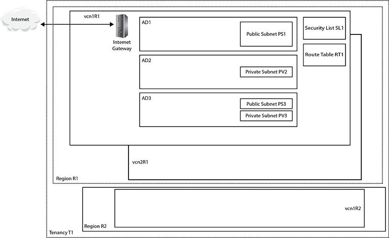
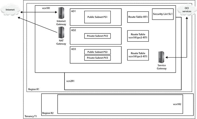
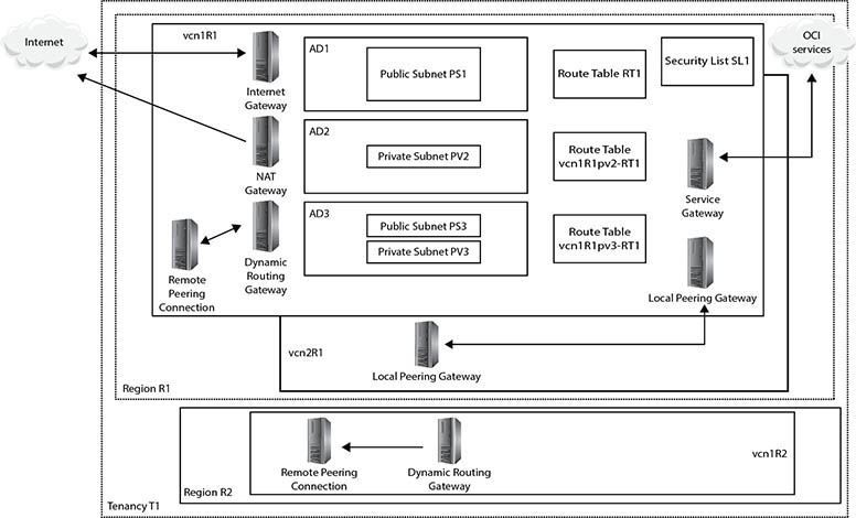
Figure 3-1 presents a shell architecture to contextualize various networking components and their interactions with other OCI and non-OCI entities discussed next.
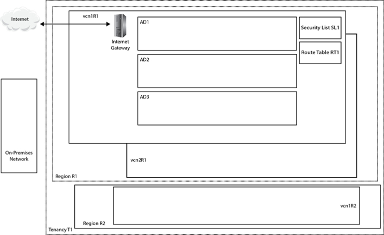
Figure 3-1 Networking concepts
At the highest level of abstraction, there are three entities: the Internet, your on-premises network, and your tenancy. Tenancy T1 is hosted in two regions, R1 and R2. These could be the us-ashburn-1 and uk-london-1 regions for example. Region R1 comprises three availability domains: AD1–3. These could be US-ASHBURN-AD-1, US-ASHBURN-AD-2, and US-ASHBURN-AD-3. Remember that ADs are physical data centers in geographically discrete locations connected by high-speed networks.
A virtual cloud network (VCN) is functionally equivalent to an on-premises network and is a private network running on Oracle networking equipment in several data centers. A VCN is a regional resource that spans all ADs in a single region and resides in a compartment. Multiple VCNs may be created in a given compartment.
Figure 3-1 shows three VCNs: vcn1R1 and vcn2R1 created in region R1, and vcn1R2 created in region R2. VCNs require several other networking resources, including subnets, gateways, security lists, and route tables in order to function. VCN resources may reside in different compartments from the VCN.
When a VCN is created through the console, one of the first decisions to be made is to specify a single contiguous IPv4 CIDR block. If you elect to create a VCN plus related resources through the console, the CIDR block of 10.0.0.0/16 is assigned by default. This specifies a range of over 65,000 addressable IP addresses.
The network prefix of the VCN CIDR block is permitted to range from /16 (over 65,000 addresses) to /30 (four host addresses, but three are reserved so only one is usable). Oracle recommends using one of the private IP address ranges specified in IETF RFC1918, section 3, where the Internet Assigned Numbers Authority (IANA) has reserved three IP blocks for private internets as per Table 3-1. This is to guarantee that this private address space is unique within your enterprise and these are not assigned to any public routable hosts.

Table 3-1 Private Address Space
The CIDR block assigned to a VCN represents a range of continuous or contiguous IP addresses. If you connect your VCN to other networks such as other VCNs (the act of connecting them is called VCN peering) or to your on-premises network, you must ensure that the CIDR blocks do not overlap. In other words, OCI will disallow network peering if there is a risk of IP address collisions.
When a VCN is created, three mandatory networking resources are created. You get a default route table, security list, and set of DHCP options created. The following subsections offer summaries of these resources.
Route Tables
Route tables contain rules that determine how network traffic coming in or leaving subnets in your VCN is routed via OCI gateways or specially configured compute instances. The default route table created when you create a VCN has no routing rules. You can add rules to the empty default route table or add your own new route tables.
Security Lists
Security lists contain firewall rules for all the compute instances using the subnet. Ingress and egress rules specify whether certain types of traffic are permitted into and out of the VCN respectively. The traffic type is based on the protocol and port and a rule can be either stateful or stateless. Stateful rules allow connection tracking and are the default, but stateless is recommended if you have high traffic volumes. Stateful rules with connection tracking allow response traffic to leave your network without the need to explicitly define an egress rule to match an ingress rule. Stateless rules, however, do not permit response traffic to leave your network unless an egress rule is defined. One of the ingress rules in the default security list allows traffic from anywhere to instances using the subnet on TCP port 22. This supports incoming SSH traffic and is useful for connecting to Linux compute instances.
DHCP Options
DHCP services provide configuration information to compute instance at boot time. You can influence only a subset of the DHCP service offerings by setting DHCP Options. These operate at a subnet level but in the absence of multiple subnet-level DHCP Options, the default set applies to all compute instances created in the VCN.
Subnets
A subnet is a portion of your network or VCN that comprises a contiguous CIDR block that is a subset of the VCN CIDR block. When a VCN plus related resources is created through the console in a region with three ADs, three subnets are also automatically created, one per AD with the default non-overlapping CIDR blocks of 10.0.0.0/24, 10.0.1.0/24, and 10.0.2.0/24. These blocks specify a range of 256 addresses per subnet. This leaves over 64,000 addresses from the VCN CIDR block that may be allocated to new subnets in your VCN. The CIDR blocks allocated to subnets must not overlap with one another. Regional subnets are also available and span all ADs in a region.
Figure 3-2 shows a new subnet that will be created in the Lab VCN in the Lab compartment, in the US-ASHBURN-AD-1 AD with the CIDR block 10.0.5.0/28. This is acceptable because this is a subset of the CIDR block 10.0.0.0/16 assigned to the VCN. If the CIDR block format is invalid, some validation checking is performed and you are informed if there are problems. If the CIDR validation check passes, you see the IP range listed below the CIDR block you entered, similar to this: Specified IP addresses: 10.0.5.0–10.0.5.15 (16 IP addresses).
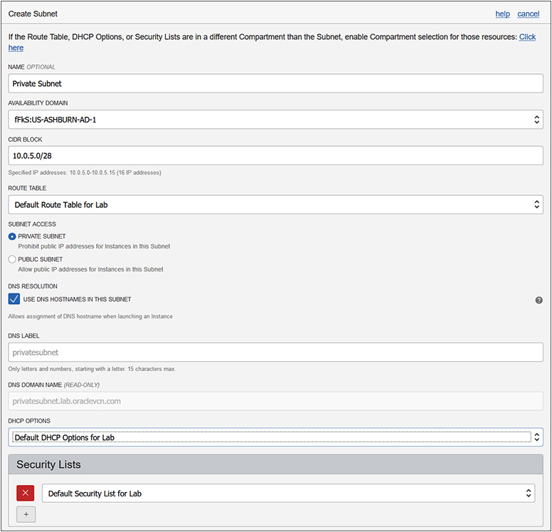
Figure 3-2 Creating a subnet
If you try to create a subnet with a CIDR block that overlaps with an existing subnet CIDR block in the same VCN, you get a message similar to this:
InvalidParameter - The requested CIDR 10.0.4.0/24 is invalid:
subnet ocid1.subnet.oc1.iad.aaaaaaa…j3axq with
CIDR 10.0.4.0/24 overlaps with this CIDR.
Another key decision to be made when creating a subnet is whether it will be private or public. Public IP addresses are prohibited for instances using private subnets, while public subnets allow instances with public IP addresses. Use public subnets if you require resources using the subnet to be reachable from the Internet; otherwise, use private subnets.
vNICs
The OCI networking service manages the association between virtual NICs (vNICs) and physical NICs on servers in OCI data centers. A vNIC resides in a subnet and is allocated to a compute instance, thus allowing the instance to connect to the subnet’s VCN. Upon launch of a compute instance, a private, unremovable vNIC is assigned to the instance and allocated a private IP address (discussed next). Secondary vNICs can be assigned to and removed from an existing instance at any time. A secondary vNIC may reside in any subnet in the VCN as long as it is in the same AD as the primary vNIC. Each vNIC has an OCID, resides in a subnet, and includes the following:
• A primary private IP address from the vNIC’s subnet, automatically allocated by OCI network services or specified by you upon instance creation.
• A maximum of 31 optional secondary private IPv4 addresses from the vNIC’s subnet, chosen either automatically or by you. For each of these optional secondary private vNICs, you can choose to have OCI network services create and assign a public IPv4 address.
• An optional DNS hostname for each private IP address (discussed later in this chapter).
• A media access control (MAC) address, which is a unique device identifier assigned to a NIC.
• A VLAN tag optionally used by bare metal instances.
• A flag to enable or check the source and destination listed in the header of each network packet traversing the vNIC, dropping those that do not conform to the accepted source or destination address.
vNIC metadata may be queried from within a compute instance using this URL: http://169.254.169.254/opc/v1/vnics/. The following example shows the vNIC metadata returned by this URL query from a compute instance with a primary private vNIC as well as details on the IP addresses assigned to all its network interfaces:
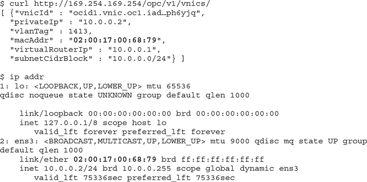
The vNIC has an OCID. The private IP address is 10.0.0.2. There are two network devices listed, a standard loopback adapter and the vNIC labeled ens3 to which the private IP address has been attached. Note the MAC address of ens3 is identical to the macAddr field returned by the metadata query. The private IP address is also in the subnet CIDR block.
Figure 3-3 shows the instance information from the console for this example compute instance. While the private IP address matches the private IP field returned by the earlier metadata query, the console also shows the public IP address: 132.145.137.53. This is the IP address used to SSH to the instance over the public Internet, yet it does not appear to be part of the local networking setup of the instance. The public IP object is actually assigned to a private IP object on the instance.
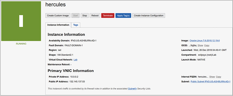
Figure 3-3 Compute instance network information
Private IP Addresses
An OCI private IP address object has an OCID and consists of a private IPv4 address and an optional DNS hostname. Each compute instance is provided a primary private IP object upon launch via the DHCP service. The private IP address cannot be removed from the instance and is terminated when the instance is terminated. As discussed in the earlier section on vNICs, you may choose to add secondary vNICs to your instance, each of which has a primary private IP object to which you can optionally assign a public IP object as long as that vNIC belongs to a public subnet.
A secondary private IP may be optionally added after an instance has launched and must come from the CIDR block of the subnet of the respective private vNIC. A secondary private IP may be moved from its vNIC on one compute instance to a vNIC on another instance as long as both vNICs belong to the same subnet. Any public IP assigned to the secondary private IP moves with it.
Public IP Addresses
A public IP address is an IPv4 address that is accessible or routable from anywhere on the Internet. Direct communication from the Internet to an instance is enabled by assigning a public IP address to a vNIC in a public subnet. An OCI public IP is defined as an object that consists of a public IPv4 address assigned by OCI Networking service, an OCID, and several properties depending on the type. There are two types of public IP addresses:
• Ephemeral addresses are transient and are optionally assigned to an instance at launch or afterwards to a secondary vNIC. These persist reboot cycles of an instance and can be unassigned at any time resulting in the object being deleted. Once the instance is terminated, the address is unassigned and automatically deleted. Ephemeral public IPs cannot be moved to a different private IP. The scope of an ephemeral IP is limited to one AD.
• Reserved addresses are persistent and exist independently of an instance. These may be assigned to an instance, unassigned back to the tenancy’s pool of reserved public IPs at any time, and assigned to a different instance. The scope of the reserved public IP is regional and can be assigned to any private IP in any AD in a region.
Public IP addresses in your VCNs are allocated from several CIDR blocks in each region. Table 3-2 lists the CIDR blocks that should be whitelisted on your on-premises or virtual networks in other clouds to support connectivity. This table is not exhaustive and lists CIDR blocks of public IPs for five OCI regions.
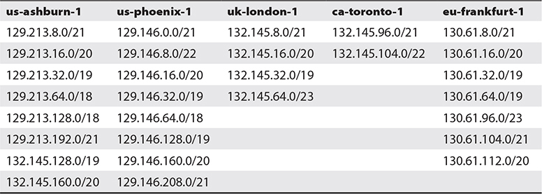
Table 3-2 OCI Public IP CIDR Blocks
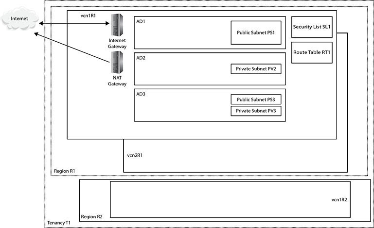
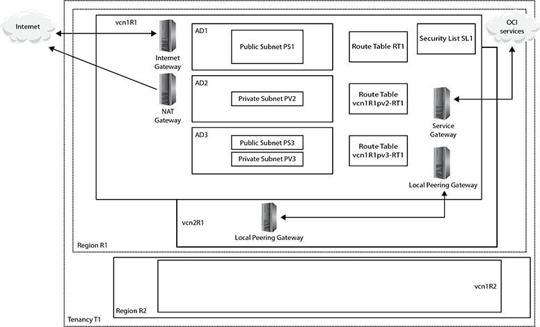
Figure 3-4 adds some detail to Figure 3-1 to illustrate the interactions between the primary OCI networking components. Instance1 AD1 is a compute instance running in AD1. It has a single vNIC with a private IP from the public subnet PS1, which has also been allocated a public IP address. Instance1 AD2 has a single vNIC with a private IP from the private subnet PV2. No public IP can be assigned to this vNIC because it is on a private subnet. Instance1 AD3 has two vNICs. The primary vNIC (vnic1) belongs to public subnet, PS3, and has both a private and public IP. The secondary vNIC(vnic2) has a private IP from the private subnet PV3. All subnets—PS1, PV2, PS3, and PV3—are non-overlapping and contained within the CIDR block of the VCN called vcn1R1. The security list SL1 and route table RT1 belong to the VCN and may be used by all networking resources within the VCN. The next section discusses the various OCI gateways shown in Figure 3-4.
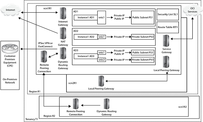
Figure 3-4 OCI networking components
Gateways
OCI uses the terminology of virtual routers and gateways interchangeably and has created several novel virtual networking components.
Internet Gateway
An Internet gateway is attached to any new VCN. It allows instances with public IP addresses to be reached over the Internet and for these instances to connect to the Internet. There is very limited configuration of this virtual router and your control is limited to the create, delete, get, list, and update commands. Here is an example of the OCI CLI get command on the Internet gateway. Internet access at a VCN level may be disabled by updating the is-enabled property of the Internet gateway to false.
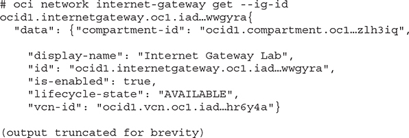
NAT Gateway
A network address translation (NAT) gateway allows instances with no public IP addresses to access the Internet while protecting the instance from incoming traffic from the Internet. When an instance makes a request for a network resource outside the VCN, the NAT gateway makes the request on behalf of the instance to the Internet and forwards the response back to the instance.
When a gateway is created in a specific compartment, a public IP address is assigned to it. This is the IP address that resources on the Internet see as the address of the incoming request.
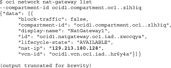
A rule must be added to the NAT gateway in the route table of a specific subnet, which is typically private. In this example, a rule is added to route table RT_PV2 to route traffic to the NAT gateway. This route table is attached to a private subnet named pv2.
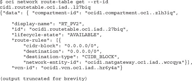
With a NAT gateway and route rule in place, instances created in the private subnet can access resources on the Internet, even though they have private IP addresses.
Dynamic Routing Gateway
Remember that when working with any cloud infrastructure you are simply connecting from your office or home computers to cloud resources through some network connection. There are several ways to connect on-premises networks to OCI, including the following:
• Direct connection over the public Internet
• Connection through customer-premises equipment (CPE) over an IPSec VPN tunnel over the public Internet
• Connection through CPE over a FastConnect private connection
Consider Instance1 AD1 in Figure 3-4. You could connect to this instance directly over the public Internet from your on-premises network using an encrypted connection. OCI instances run either Linux or Windows operating systems. You can connect to Instance1 AD1 from your on-premises network using SSH or RDP protocols depending on whether your instance is running Linux or Windows and the security list’s ingress rules permit SSH or RDP connections from your location. Your commands are encrypted before leaving the on-premises network, transmitted over public Internet connections, decrypted, and executed on the instance.
There are several concerns with this approach. Primarily, the security concern is that sensitive data should not be transported over public Internet connections, and the performance concern is that network latency over the public Internet can be erratic and unpredictable.
To alleviate these concerns, you may set up a connection between your on-premises network’s edge router (CPE or customer-premises equipment) and an OCI component known as a Dynamic Routing Gateway (DRG). A DRG is a VCN-level device that extends your on-premises network into your VCN. It is important to think of a DRG as a gateway that provides a private path between discrete networks. Figure 3-4 shows a DRG in vcn1R1 in region R1 connecting to the CPE at the edge of the on-premises network.
Instance1 AD2 has only a private IP address and is reachable by other instances in the same private subnet or in other subnets in your region and tenancy, assuming appropriate security lists are in place, but it is not reachable over the Internet. Instance1 AD3 can connect to Instance1 AD1 through either a public or private IP address. If the connection is through the public IP, then traffic will flow from Instance1 AD3 to the Internet gateway, which routes it to Instance1 AD1 without sending the traffic over the Internet. The shorter and more secure route would be for these instances to communicate with each other over their private IP addresses.
The network path between the CPE and DRG can be a set of redundant IPSec VPN tunnels or over FastConnect. IPSec VPNs offer end-to-end encrypted communications thereby improving security. The tunnels still run over public networks, which makes them more affordable but less secure than using FastConnect. When an IPSec VPN is set up, two tunnels are created for redundancy.
OCI provides FastConnect as a means to create a dedicated high-speed private connection between on-premises networks and OCI. FastConnect provides consistent, predictable, secure, and reliable performance. FastConnect supports the following uses:
• Private peering extends your on-premises network into a VCN and may be used to create a hybrid cloud. On-premises connections can be made to the private IP addresses of instances as if they were coming from instances in the VCN as in the connection between Instance1 AD1 and Instance1 AD3 described earlier. Private peering can also occur between instances in VCNs in other regions.
• Public peering allows you to connect from resources outside the VCN, such as on-premises network, to public OCI services, such as object storage, without traversing the Internet over FastConnect.
FastConnect is actualized using several connectivity models:
• Colocation with Oracle allows direct physical cross-connects between your network and Oracle’s FastConnect edge devices.
• Using an Oracle Network Provider or Exchange Partner, you can set up a FastConnect connection from your network to the provider or partner network that has a high bandwidth connection into Oracle’s FastConnect edge devices.
• Using a third-party provider that is not a FastConnect partner but is typically an MPLS VPN provider who sets up a private or dedicated circuit between your on-premises network and Oracle’s FastConnect edge devices.
When a DRG object is created, it is assigned an OCID. DRGs may be attached to or detached from a VCN. A VCN can have only one DRG attached at a time. A DRG can be attached to only one VCN at a time, but may be detached from one VCN and attached to another. A DRG may also be used to provide a private path that does not traverse the Internet between VCNs in different regions. Once a DRG is attached to a VCN, the route tables for the VCN or specific subnets must be updated to allow traffic to flow to the DRG.
Service Gateway
A service gateway allows OCI instances to access OCI services (which are not part of your VCN) using a private network path on OCI network fabric without needing to traverse the Internet. A service gateway gets an OCID and is a regional resource providing access to OCI services to the VCN where it resides without using an Internet or NAT gateway.
The steps to set up a working service gateway are as follows:
1. Create the service gateway in a VCN and compartment, and choose the services that will be accessed through the service gateway. For example, you may create a service gateway named SG1, which accesses the OCI Object Storage service in that region. The storage gateway is open for traffic by default upon creation but can be set to block traffic at any time.
2. Add a route table rule to direct traffic for a destination service to the target service gateway. For example, you can add a rule with the target type Service Gateway in the Lab compartment for all traffic to the destination: OCI Object Storage service to go through the SG1 gateway as per Figure 3-5. Prior to deleting the service gateway, you must first delete this route rule to avoid errors.
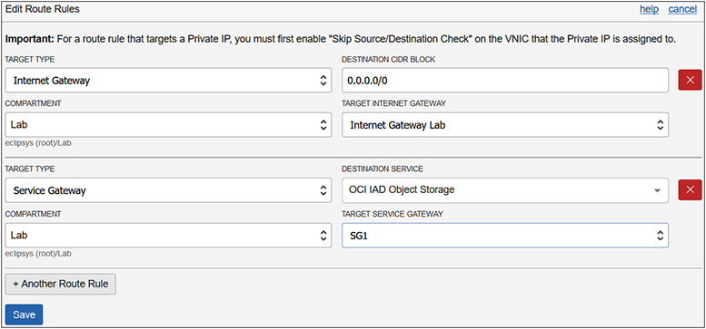
Figure 3-5 Route table rule for service gateway
3. You may have to update the security list in your VCN to allow traffic associated with the chosen service. For example, the object storage service requires a stateful egress rule to allow HTTPS traffic.
4. The previous three steps will allow access to all resources in the VCN to access object storage. It is prudent to use IAM policies (discussed in Chapter 2) to limit access to specific object storage buckets. The following rule permits members of the ESC_DBAs group to manage the object storage bucket named DB_Backups.

A good use case for the service gateway relates to reading and writing database backups to object storage from private networks. A database typically resides on a compute instance in a private subnet. You could back up the database to an object storage bucket without needing public IP addresses or access to the Internet by using a service gateway.
In the following example, an object storage bucket named DB_Backups has been created in the Lab compartment. Using the OCI CLI tool, the bucket is listed here:

A 30GB file is created and copied to the bucket using the OCI CLI. The OCI instance has a public IP address and is on a VCN with functional Internet access through an Internet gateway but with no service gateway:
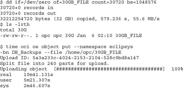
The file upload operation takes just over ten minutes. The same test is performed with an instance with only a private IP in a private subnet in the same VCN with a service gateway named SG1:

Two interesting observations emerged from this test. First, the instance with the private IP successfully accessed the object storage bucket through the service gateway. Second, the IO performance was almost identical, which makes sense because the Internet gateway in the first test routed the file transfer from the instance over internal OCI networks and not the public Internet, which is a similar path that the file traveled through the service gateway. Remember that without the service gateway, the instance with the private IP cannot see the object storage, but its IO performance is not negatively impacted by the service gateway.
Local Peering Gateway
You may create multiple VCNs with non-overlapping CIDR ranges in a region. Using the reserved IP blocks in Table 3-1, you may have vcn1R1 with CIDR 10.0.0.0/8 and vcn2R1 with CIDR 192.168.0.0/16, for example. Each VCN has zero or more public or private subnets per AD with zero or more compute instances with private IP addresses and possibly some with public IPs. An instance in one VCN can connect to another instance in the same VCN using either a public or private IP, but can connect only to the public IP of instances in different VCNs (as long as an Internet gateway, relevant route table entries, and security lists are in place).
A local peering gateway (LPG) allows VCNs in the same region, regardless of tenancy, to act as peers and supports instances in one VCN connecting to instances in another VCN using private IP addresses. This is known as local VCN peering and requires the following:
• Two VCNs in the same region with non-overlapping CIDR ranges
• A connected local peering gateway in each VCN
• Route table rules enabling traffic flow over the LPGs between specific subnets in each VCN
• Security lists egress and ingress rules controlling traffic between instances from each VCN
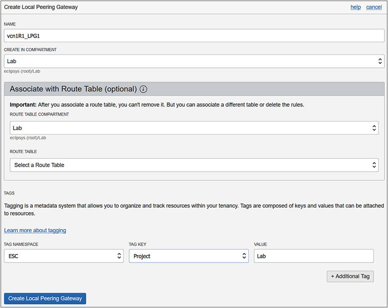
Figure 3-6 shows the VCN vcn1R1 in the Lab compartment with local peering set up with CIDR block: 192.168.0.0/16. This VCN is peered using LPG vcn1R1_LPG to another VCN with an advertised CIDR block: 10.0.0.0/16.
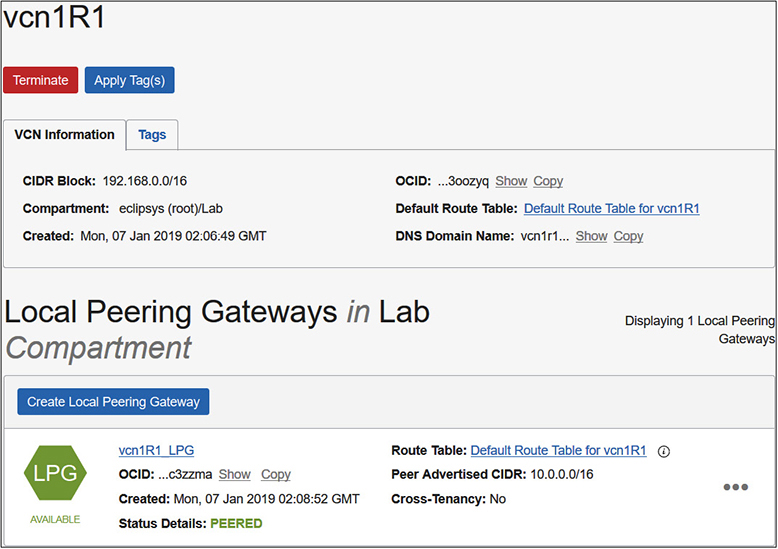
Figure 3-6 Local peering gateway
Remote Peering Connection
While local peering connects VCNs in the same region even across tenancy, remote peering connects VCNs in the same tenancy across regions. Remote peering allows instances in regionally separated VCNs to communicate using their private IP addresses. A DRG must be attached to each remote VCN to be peered. A remote peering connection (RPC) is created on the DRG in both regionally separated VCNs. One VCN is designated a requestor role while the other is the acceptor. The requestor initiates the peering request and specifies the OCID of the RPC that belongs to the acceptor. You can have a maximum of ten RPCs per tenancy, as of this writing. Remote VCN peering requires the following:
• Two VCNs in the same tenancy that reside in different regions with non-overlapping CIDR ranges.
• A DRG attached to each VCN that will participate in the remote peering connection.
• A remote peering connection (RPC) component created on each DRG. The connection is enabled by the requesting VCN by supplying the OCID of the RPC of the accepting VCN.
• Route table rules enabling traffic flow over the DRGs between specific subnets in each VCN.
• Security lists with egress and ingress rules to control traffic between instances from each VCN.
Figure 3-7 shows the requesting RPC named RPC_vcn1R1-vcn1R2 with status: PEERED. This RPC is created as a component on the DRG named DRG_VCN1R1. This configuration permits instances in vcn1R1 to communicate with instances in vcn1R2 using their private IP addresses.
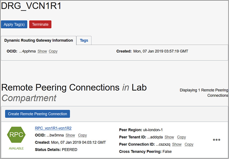
Figure 3-7 Remote peering connection
Use Virtual Cloud Networks
The previous section provided a theoretical basis for VCN-related components. It is time to get your hands dirty. This section consists of five exercises designed to get you familiar with using virtual cloud networks. You will start by creating a number of VCNs with several private and public subnets in both your home and another region in your tenancy. These exercises are based on regions with 3 ADs. To follow along, try to use two similarly resourced regions. Some VCNs will have overlapping CIDR ranges while others will not. Once the VCNs and subnets are created, you will deploy a NAT gateway to enable Internet access for one of the private subnets. A service gateway will be deployed to allow another private subnet access to the OCI object storage service. Finally, you will set up local and remote VCN peering.
Exercise 3-2: Create VCNs and Subnets
If you have been working through the chapters in order, your tenancy should already be subscribed to one non-home region. In this exercise, you will create three VCNs, two in your home region and one in a secondary region, and several public and private subnets. This exercise is based on regions with 3 ADs.
1. Sign in to the OCI console.
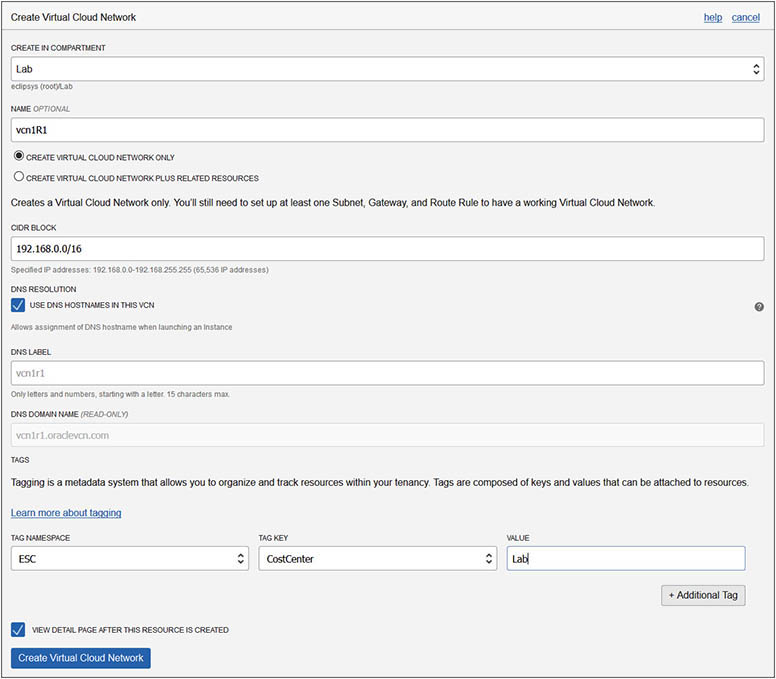
2. In your home region, navigate to Networking | Virtual Cloud Networks. Choose Create Virtual Cloud Network. Choose the compartment in your tenancy that will hold these networking components. The compartment used in the exercise is called Lab, but you should use a compartment that is meaningful in your environment. Provide a VCN name: vcn1R1. Choose Create Virtual Cloud Network Only. Provide a CIDR block for the VCN: 192.168.0.0/16. Leave the DNS options at the defaults, apply any relevant tags, and choose Create Virtual Cloud Network. After a few moments, your new barebones VCN is provisioned.
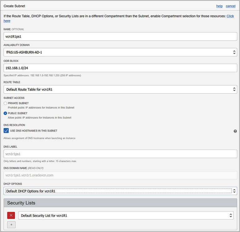
3. Choose the newly created VCN from Networking | Virtual Cloud Networks and choose Create Subnet. Provide a name: vcn1R1ps1. Choose the first AD in your region for this subnet—for example, fFkS:US-ASHBURN-AD-1. Provide a CIDR block for this subnet that must be a subset of the VCN CIDR range but must also not overlap with other subnets in the VCN—for example, 192.168.1.0/24. Choose the default route table for vcn1R1. For subnet access, choose Public Subnet. This is an important choice that cannot be updated later. The only subnet options that may be updated later are the subnet name, the DHCP options, route table, security lists, and tags. Leave the DNS, DHCP options, and security lists at defaults; apply any relevant tags; and choose Create. After a few moments, your subnet is provisioned. The fFks prefix to the AD is a tenancy-specific prefix allocated by OCI to keep track of which AD corresponds to which data center for each tenancy. This is required because OCI load balances tenancies across the ADs in a region randomly. In the same region, the data center that is called AD1 in your tenancy may be different from AD1 in another tenancy.
4. Repeat Steps 2 and 3 using the adjacent table data to create the three remaining subnets for vcn1R1, using the default route table, DHCP options, and security list. For vcn2R1 and vcn1R2, choose Create Virtual Cloud Network Plus Related Resources. Create vcn1R2 in your non-home region—for example, uk-london-1. The naming convention employed for subnets in this exercise references the AD number to which the subnet belongs.

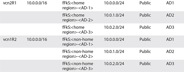
5. Notice that with vcn2R1 and vcn1R2, because you chose Create Virtual Cloud Network Plus Related Resources, the CIDR block defaults to 10.0.0.0/16 and cannot be changed. Additionally, three public subnets (one in each AD) with CIDR blocks 10.0.0.0/24, 10.0.1.0/24, and 10.0.2.0/24 are provisioned.
6. In your home region, create an Internet gateway for vcn1R1. Navigate to Networking | Virtual Cloud Networks. Choose vcn1R1. Then click Internet Gateways in the Resources list on the left and choose Create Internet Gateway. Provide a name: Internet Gateway vcn1R1 and then optionally tag the resource and select Create Internet Gateway.
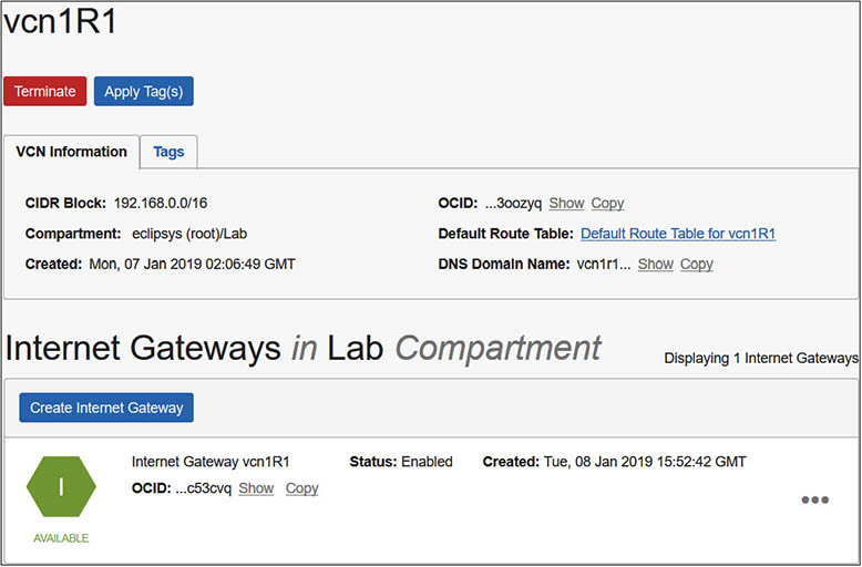
7. You should now have three VCNs, each with default route tables, security lists, and DHCP options. Each VCN created with related resources (vcn2R1 and vcn1R2) has three public subnets and one Internet gateway provisioned. The manually provisioned VCN (vcn1R1) has two private and two public subnets and one manually created Internet gateway.
Exercise 3-3: Deploy a NAT Gateway
This exercise builds on the infrastructure you created in Exercise 3-2. In this exercise, you will deploy a NAT gateway in VCN, vcn1R1, to enable outgoing Internet access for instances created in a private subnet: vcn1R1pv2.
1. Sign in to the OCI console.
2. In your home region, navigate to Networking | Virtual Cloud Networks | vcnR1 | NAT Gateways. Choose Create NAT Gateway. Choose the compartment in your tenancy that will hold these networking components. The compartment used in the exercise is called Lab, but you should use a compartment that is meaningful in your environment. Provide a NAT Gateway name: vcn1R1-NAT-GW1. Choose Create.
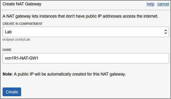
3. After a few moments, your gateway is created. A notification reminds you to add a route rule for any subnet that needs to use this NAT gateway and to ensure that the NAT gateway is in the AVAILABLE state. Note that once the NAT gateway is available, you can stop all traffic going to the Internet from private networks in the VCN by choosing the Block Traffic option on the NAT gateway. Also note the public IP address that has been allocated to the NAT gateway allowing it to access the Internet.
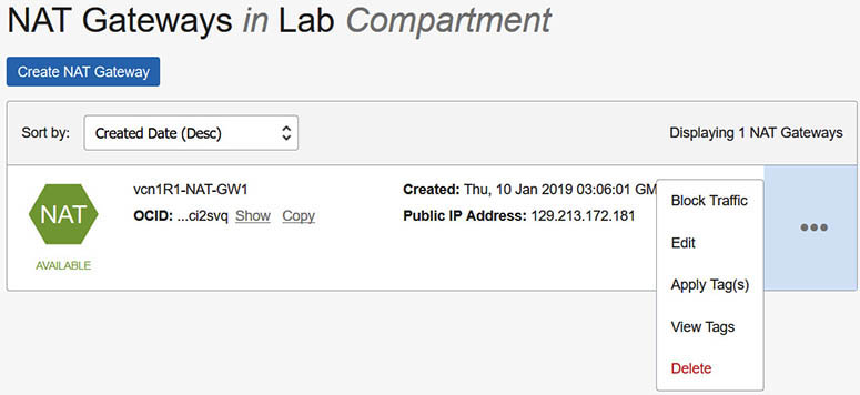
4. For instances in a subnet to actually use the NAT gateway, route rules must be added to the route table associated with the subnet. When the private subnet vcn1R1pv2 was created, the default route table of the VCN was chosen as its route table. You will create a new route table, add a route rule, and update the private subnet to use the new route table. In your home region, navigate to Networking | Virtual Cloud Networks | vcnR1 | Route Tables. Choose Create Route Table. Choose the compartment of the subnet and provide a name: vcn1R1pv2-RT1. Add a route rule by selecting NAT Gateway as the Target Type, the compartment where the NAT gateway resides, vcn1R1-NAT-GW1 as the Target NAT Gateway, and a destination CIDR block of 0.0.0.0/0. Any subnet traffic with a destination that matches the rule (and not handled by a more selective route table entry if one is later added) is routed to the NAT gateway except for intra-VCN traffic, which is routed to the target in the VCN. Select Create Route Table.

5. The new route table is not yet associated with the private subnet. Navigate to Networking | Virtual Cloud Networks | vcnR1-Subnets and choose the Edit option adjacent to subnet vcn1R1pv2. Choose the new route table, vcn1R1pv2-RT1, in the Route Table section as the new route table for this subnet and select Update.
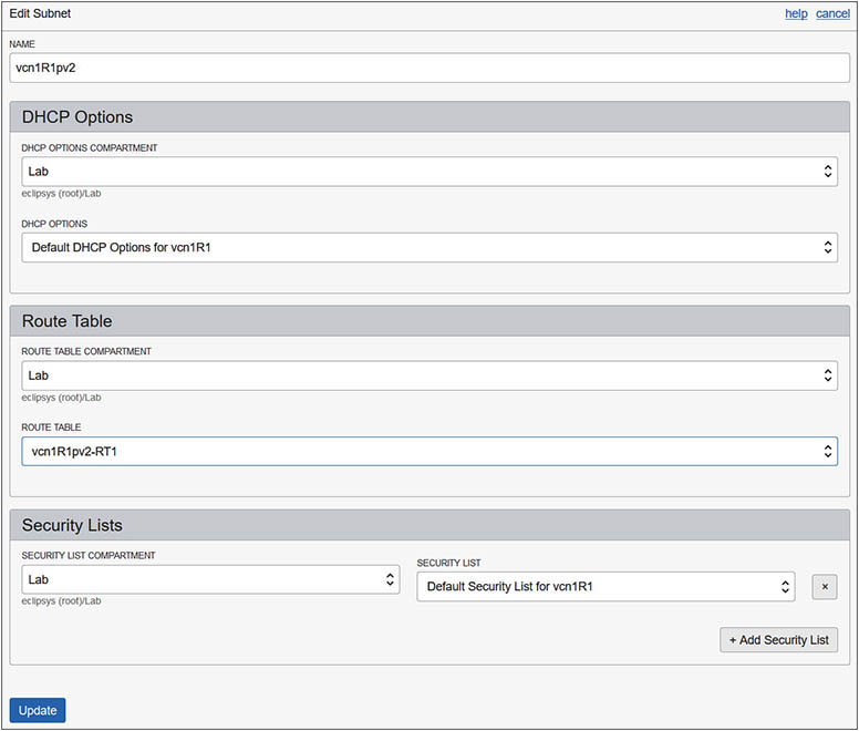
6. Instances created in subnet vcn1R1pv2 will receive private VNICs and private IPs from the CIDR block of the subnet. The NAT gateway, route table, and route rule created previously (plus the egress rule from the default security list) will allow these instances to connect to the Internet.
Exercise 3-4: Deploy a Service Gateway
This exercise builds on the infrastructure you created in Exercise 3-3. In this exercise, you will deploy a service gateway in VCN vcn1R1, to enable OCI object storage access for instances created in private subnet vcn1R1pv3. Instances in this subnet do not have Internet access because it is private, so the VCN’s Internet gateway cannot be used. Although the NAT gateway created in Exercise 3-3 exists at the VCN level, there are no route rules in the VCN’s default route table currently used by this subnet to allow Internet-bound traffic out of the subnet. In this exercise, you will create a service gateway and a new route table (vcnR1pv3-RT1), and update the route table used by the subnet: vcnR1pv3.
1. Sign in to the OCI console.
2. In your home region, navigate to Networking | Virtual Cloud Networks | vcnR1 | Service Gateways. Choose Create Service Gateway. Choose the compartment in your tenancy that will hold these networking components. The compartment used in the exercise is called Lab, but you should use a compartment that is meaningful in your environment. Provide a service gateway name: vcn1R1-Service-GW1. Choose the OCI services to which this gateway will allow access, such as OCI IAD Object Storage, and select Create.
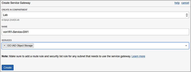
3. After a few moments, your gateway is created. A notification reminds you to add a route rule and security list rule for any subnet that needs to use this service gateway and to ensure that it is AVAILABLE. Similar to the NAT gateway, you can stop all traffic going to the OCI service selected from instances using the gateway by choosing the Block Traffic option.
4. For instances in subnet vcnR1pv3 to access object storage through the service gateway, route rules must be added to the route table associated with the subnet. You will create a new route table with a route rule for the service gateway and update the private subnet to use the new route table. In your home region, navigate to Networking | Virtual Cloud Networks | vcnR1 | Route Tables. Choose Create Route Table. Choose the compartment of the subnet and provide a name: vcn1R1pv3-RT1. Add a route rule by selecting Service Gateway as the Target Type, the compartment where the service gateway resides, vcn1R1-Service-GW1 as the Target Service Gateway, and a destination service like OCI IAD Object Storage. Select Create Route Table.
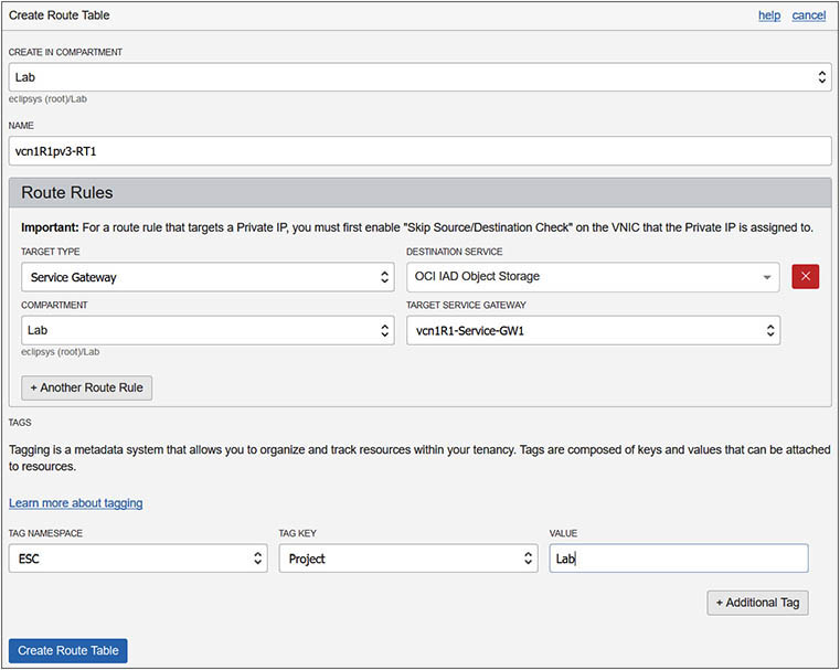
5. The new route table is not yet associated with the private subnet. Navigate to Networking | Virtual Cloud Networks | vcnR1 | Subnets and choose the Edit option adjacent to subnet vcn1R1pv3. Choose the new route table, vcn1R1pv3-RT1, in the Route Table section as the new route table for this subnet and select Update.
6. Any traffic from instances in this subnet trying to access OCI object storage will be routed through the storage gateway provided the security list allows the outgoing or egress traffic. Navigate to Networking | Virtual Cloud Networks | vcnR1 | Security Lists and choose the View Security List Details option adjacent to the default security list. Choose Edit All Rules. Scroll to the Allow Rules for Egress section. Choose Service as the destination type and the OCI service, such as OCI IAD Object Storage, as the destination service. To allow only HTTPS secure calls to be made to object storage, choose TCP as the IP protocol and set the destination port range to 443. The source port range can be optionally specified or left as All. Select Save Security List Rules.
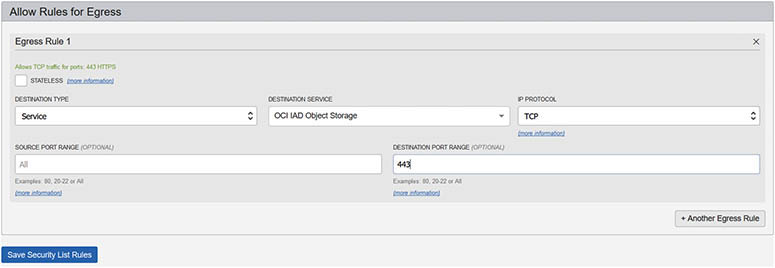
7. After you set up the service gateway, route table, and security list rule, instances created in the vcn1R1pv3 subnet can access OCI object storage services over the OCI network fabric.
Exercise 3-5: Set Up Local VCN Peering
This exercise builds on the infrastructure you created in Exercise 3-4. In this exercise, you will set up local VCN peering, allowing instances in vcn1R1 (192.168.0.0/16) to communicate with instances in vcn2R1 (10.0.0.0/16) using their private IPs and having none of their traffic traverse the public Internet. These VCNs meet the requirements for local peering because they have non-overlapping CIDR blocks and reside in the same region.
Peering relies on the agreement between the administrators of both VCNs. In this example, you are the administrator of both local VCNs. One VCN administrator is designated as the requestor while the other is the acceptor. The requestor initiates the peering request, while the acceptor permits the requestor to connect to the local peering gateway. IAM policies, routing rules, and security list rules are also required to complete the setup.
1. Sign in to the OCI console.
2. Both the requestor and acceptor must create a local peering gateway in each VCN. For this exercise, vcn1R1 will be the requesting side while vcn2R1will be the accepting side.
3. In your home region, navigate to Networking | Virtual Cloud Networks | vcn1R1 | Local Peering Gateways. Choose Create Local Peering Gateway. Provide a name: vcn1R1_LPG1. Choose the compartment in your tenancy that will hold this networking component. Leave the route table options at default values and select Create Local Peering Gateway. Repeat these steps in vcn1R2 to create the accepting side LPG called vcn2R1_LPG1.
4. Once vcn2R1_LPG1 is created, take note of its OCID. Because this peering is between VCNs in the same tenancy, the LPGs of both the acceptor and requestor can be chosen from a list of values. For cross-tenancy peering in the same region, you will require the OCID, which may resemble this format:
ocid1.localpeeringgateway.oc1.iad...mjcpq
5. For local peering between VCNs in the same tenancy, an IAM policy must be created to allow users from the requestor side to initiate a connection from the LPG in the requestor’s compartment. An IAM policy on the acceptor’s side must be created to allow the requestor’s LPG to establish a connection to the acceptor’s LPG.
6. IAM policies for cross-tenancy peering are slightly more complex, requiring additional policy statements endorsing requestor groups to manage LPGs in the acceptor’s tenancy and to associate LPGs in the requestor’s compartment with LPGs in the acceptor’s tenancy. Corresponding policy statements on the acceptor’s side admit the requestor’s group to manage LPGs in the acceptor’s compartment and to associate LPGs in the requestor’s compartment with LPGs in the acceptor’s compartment.
7. In this exercise, you will forego the IAM policy creation. In practice, while this step is relatively important for local peering between VCNs in the same tenancy, it is essential for cross-tenancy local peering.
8. The requestor must perform the task of establishing the connection between the two LPGs. Navigate to Networking | Virtual Cloud Networks | vcn1R1 | Local Peering Gateways | vcn1R1_LPG1, and choose Establish Peering Connection. You are peering two VCNs in the same tenancy so leave the radio button at its default setting, allowing LPGs to be browsed. Choose the acceptor VCN compartment (Lab), the requestor VCN name (vcn2R1), the compartment name where the acceptor’s LPG resides, as well as the name of the acceptor’s LPG (vcn2R1_LPG1) and choose Establish Peering Connection.
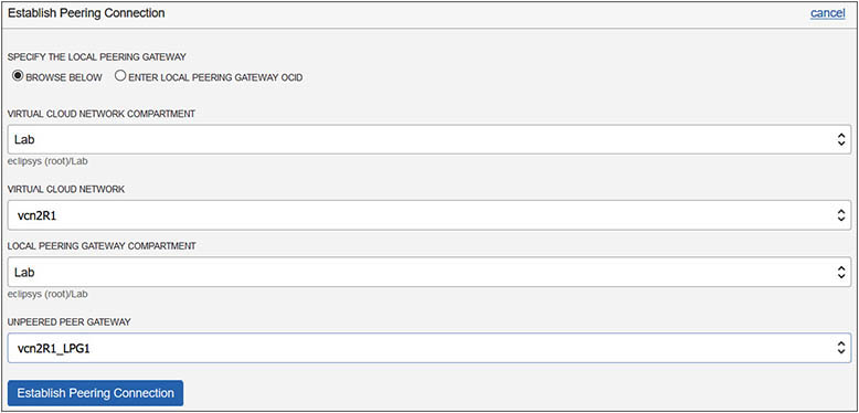
9. After a few moments, the peering status on the requestor and acceptor LPGs changes from PENDING to PEERED. The requestor’s LPG, vcn1R1_LPG1, has information about the requestor’s VCN, CIDR Block:192.168.0.0/16, and the acceptor’s VCN, Peer Advertised CIDR:10.0.0.0/16.

10. The acceptor’s LPG: vcn2R1_LPG1 has information about the acceptor’s VCN, CIDR Block: 10.0.0.0/16, and the acceptor’s VCN, Peer Advertised CIDR, 192.168.0.0/16.
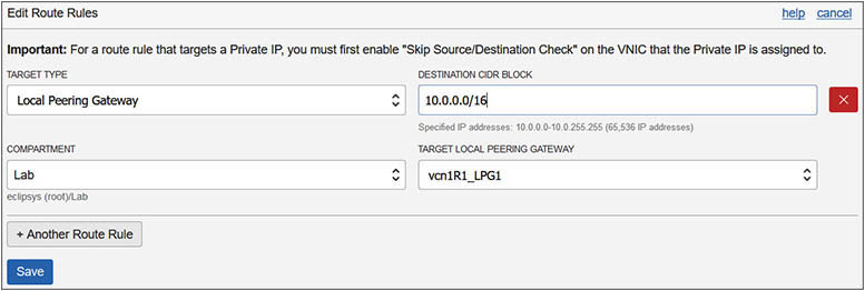
11. The peer-advertised CIDR blocks above must be added to the route tables of each VCN to direct requestor traffic to the acceptor’s VCN and vice versa. Navigate to Networking | Virtual Cloud Networks | vcn1R1 | Route Tables | Default Route Table for vcn1R1 and choose Edit Route Rules. Choose +Another Route Rule. Choose Local Peering Gateway as the target type; the compartment of the target LPG, Lab; the name of the target LPG, vcn1R1_LPG1, and the destination CIDR block, 10.0.0.0/16; and select Save. This rule will allow traffic from instances in vcn1R1 with private IP addresses from the CIDR range: 192.168.0.0/16 trying to access instances with private IP addresses from the 10.0.0.0/16 range to connect through the LPG.
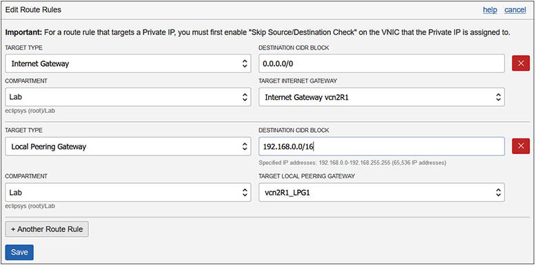
12. Update the default route table on the acceptor’s VCN as follows: Navigate to Networking | Virtual Cloud Networks | vcn2R1 | Route Tables | Default Route Table for vcn2R1 and choose Edit Route Rules. Choose +Another Route Rule and add Local Peering Gateway as the target type; the compartment of the target LPG, Lab; the name of the target LPG, vcn2R1_LPG1; and the destination CIDR block, 192.168.0.0/16, and select Save.
13. The last configuration step required is to set up ingress and egress rules if necessary to allow instances from each VCN to connect to each other. In this exercise, SSH access on TCP port 22 is sufficient but you may want to allow access to database listener ports or HTTPS ports. The requestor’s default security list should be updated by navigating to Networking | Virtual Cloud Networks | vcn1R1 | Security Lists | Default Security List for vcn1R1 and choosing Edit All Rules. There is already an ingress rule allowing incoming traffic from any IP address (0.0.0.0/0) to TCP port 22, so you only need to add an egress rule. Choose +Another Egress Rule, and select CIDR as the destination type with any IP address (0.0.0.0/0) as the destination CIDR, TCP as the protocol, and 22 as the destination port range.

14. The default security list for vcn2R1 already has default ingress and egress rules that permit instances to SSH externally and to accept incoming SSH traffic.
15. With local VCN peering enabled, instances in vcn1R1 are thus able to communicate with instances in vcn2R1 using their private IPs over SSH.
Exercise 3-6: Set Up Remote VCN Peering
This exercise builds on the infrastructure you created in Exercise 3-5. In this exercise, you will set up remote VCN peering, allowing instances in vcn1R1(192.168.0.0/16) to communicate with instances in vcn1R2 (10.0.0.0/16) using their private IPs and having none of their traffic traverse the public Internet despite these VCNs residing in different regions. These VCNs meet the requirements for remote peering because they have non-overlapping CIDR blocks and reside in different regions.
Like local peering, remote peering relies on the agreement between the administrators of both VCNs, one designated the requestor while the other is the acceptor. The requestor initiates the peering request while the acceptor permits the requestor to connect to the peering mechanism.
1. Sign in to the OCI console
2. Both the requestor and acceptor must create a dynamic routing gateway (DRG) in each VCN. For this exercise, vcn1R1 will be the requesting side while vcn1R2 will be the accepting side.
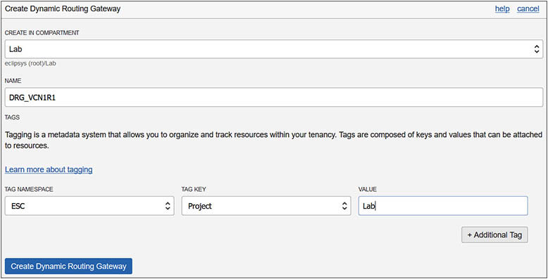
3. In your home region, navigate to Networking | Dynamic Routing Gateways, and choose Create Dynamic Routing Gateway. Choose the compartment in your tenancy that will hold the networking component Lab, provide the name DRG_VCN1R1, and choose Create Dynamic Routing Gateway. Repeat this step in your non-home region and create a DRG named DRG_VCN1R2.
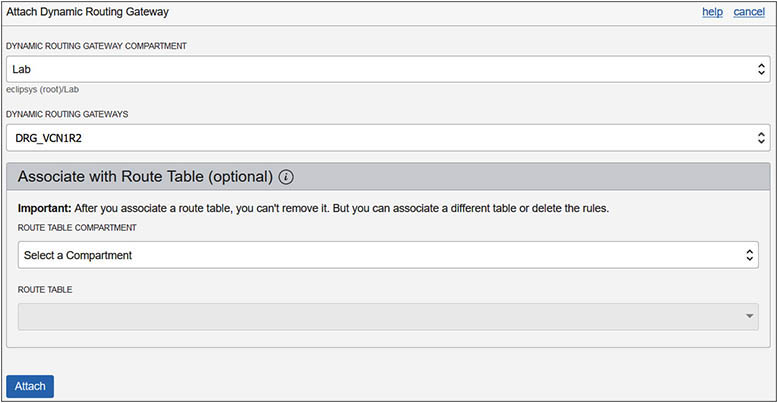
4. Attach the DRGs to your VCNs. Navigate to Virtual Cloud Networks | vcn1R1 | Dynamic Routing Gateways, and choose Attach Dynamic Routing Gateway. Choose the DRG’s compartment and the DRG_VCN1R1, and select Attach. Repeat this step in your non-home region and attach DRG_VCN1R2 to vcn1R2.
5. Remote peering connections (RPCs) must also be created in each DRG. Navigate to Virtual Cloud Networks | vcn1R1 | Dynamic Routing Gateways | DRG_VCN1R1 | Remote Peering Connections, and choose Create Remote Peering Connection. Provide a name, RPC_vcn1R1-vcn1R2, and the compartment, Lab, and select Create Remote Peering Connection. Repeat this step in your non-home region and create RPC_vcn1R2-vcn1R1 in DRG_VCN1R2. Take note of the OCID of the acceptor’s RPC, which should resemble the following:
ocid1.remotepeeringconnection.oc1.uk-london-1...xyxfa

6. Similar to the LPG setup, IAM policies must be set up. The requestor should have a policy permitting connections from the requestor’s compartments to be initiated from the RPC, while the acceptor permits the requestor’s group to connect to the acceptor’s RPC. Once again, this step is skipped, although in practice, this is important for network security.
7. The requestor must establish the connection between the RPCs. Navigate to Networking | Dynamic Routing Gateways | DRG_VCN1R1 | Remote Peering Connections | RPC_vcn1R1-vcn1R2 and choose Establish Connection. Choose the acceptor’s region, uk-london-1; provide the OCID of the acceptor’s RPC; and select Establish Connection. After a few moments, the state of both the requestor’s and acceptor’s RPCs changes from PENDING to PEERED.

8. Remember that both vcn2R1 and vcn1R2 use CIDR block (10.0.0.0/16). It is entirely possible that instance1_vcn1R1 may have private IP address 192.168.0.5 while instance2_vcn2R1 has private IP address 10.0.0.4, and instance3_vcn1R2 also has private IP address 10.0.0.4. What happens if instance1_vcn1R1 tries to connect to 10.0.0.4? If you followed the exercises in sequence, then the LPG route rule will direct the traffic to instance2_vcn2R1. With remote peering, it becomes more complicated. You have to decide which subnets in vcn1R1 need to access vcn1R2 and configure routing accordingly. If you try to add a rule to the default route table that points to the same destination CIDR block as another rule, you get an error stating that you cannot add multiple rules with the same destination.
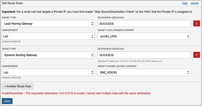
9. To correctly route traffic between the remotely peered VCNs, you decide that only traffic from subnet vcn1R1pv2 will access the remote VCN, so you update the route table for this subnet on the requestor’s VCN as follows: Navigate to Networking | Virtual Cloud Networks | vcn1R1 | Route Tables | vcn1R1pv2-RT1, and choose Edit Route Rules. Choose +Another Route Rule and add Dynamic Routing Gateway as the target type; the compartment of the target DRG, Lab; the name of the target, DRG: DRG_VCN1R1; and the destination CIDR block, 10.0.0.0/16. Select Save.
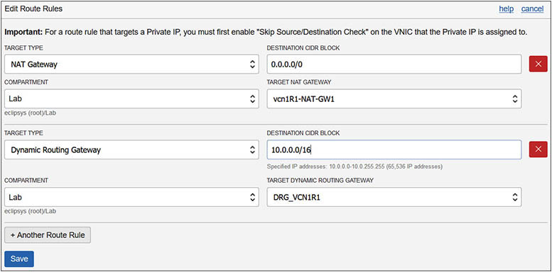
10. The last configuration step required is to set up ingress and egress rules if necessary to allow instances from each VCN to connect to one another. In the previous exercise, the requestor’s default security list was updated, permitting ingress and egress traffic on any IP address (0.0.0.0/0) on TCP port 22, but tweak this as necessary.
11. The default security list for vcn1R2 already has default ingress and egress rules that permit instances to SSH externally and to accept incoming SSH traffic.
12. With remote VCN peering enabled, instances in subnet vcn1R1pv2 are thus able to communicate with instances in vcn1R2 using their private IPs over SSH.
DNS in OCI
A hostname is a name provided to a computer or host either explicitly or through the DHCP service discussed earlier. The Domain Name System (DNS) is a directory that maps hostnames to IP addresses. The OCI DNS service is a regional service. This section describes DNS concepts and features in OCI as well as several advanced DNS topics, including zone management and creating and managing DNS records.
DNS Concepts and Features
DNS evolved from a centralized text file that mapped hostnames to IP addresses to computers on the early Internet to a decentralized hierarchy of name servers, each responsible for assigning domain names and mapping these to Internet resources. The DNS server hierarchy starts with top-level domains (TLDs) like com and org, most of which are administered by ICANN (Internet Corporation for Assigned Names and Numbers), which operates IANA (Internet Assigned Numbers Authority), which is responsible for maintaining the DNS root zone, which contains the TLDs.
All domains below the TLDs are subdomains that inherit their suffix from their parent domain. For example, in the domain oraclevcn.com, the top-level domain is com and authority over the subdomain oraclevcn.com has been delegated to a lower-level DNS server. A DNS zone is a distinct part of a domain namespace, like the oraclevcn.com subdomain, where the administration has been delegated to an organization, in this case Oracle Corporation.
Administration of DNS zones may be delegated to either a person or organization. If a DNS server has authority over a domain, it is designated as an authoritative name server, and it maintains copies of domain resource records for that zone. The application that runs on virtually all DNS servers is called BIND (Berkeley Internet Name Domain). BIND uses a file format for defining resource records (RRs) in DNS zones known as a zone file. DNS zones are discussed in the next section.
During the subnet creation phase, you can choose whether to use DNS hostnames in the subnet or not. Hosts that join a network that allows DNS resolution are provided with a domain name. If you have a database server with hostname prod, and your network domain is named oracle.com, the server would have the fully qualified domain name (FQDN) prod.oracle.com. A domain like oracle.com is sometimes referred to as a DNS suffix, as this is appended onto a hostname to form the FQDN. Figure 3-8 shows the OCI console interface for creating a public subnet named ps3 in AD-3 with CIDR block 10.0.6.0/24. Note the DNS resolution section where the option to Use DNS Hostnames In This Subnet is checked. The DNS label is copied from the subnet name but can be overridden while the DNS domain name is derived from the DNS label and VCN domain name.
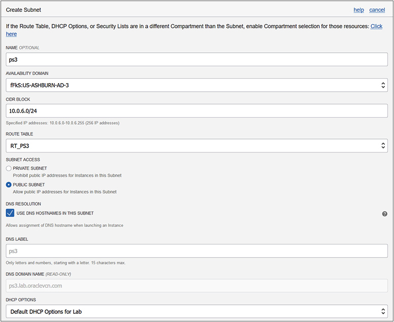
Figure 3-8 Setting DNS options while creating a subnet
DNS labels are validated for compliance and uniqueness during instance launch and should adhere to these guidelines:
• VCN domain name: <VCN DNS label>.oraclevcn.com. The VCN DNS label should preferably be unique across your VCNs but is not mandatory.
• Subnet domain name: <subnet DNS label>.<VCN DNS label>.oraclevcn.com. The subnet DNS label must be unique in the VCN.
• Instance FQDN: <hostname>.<subnet DNS label>.<VCN DNS label>.oraclevcn.com. The hostname must be unique within the subnet.
DNS supports communication between devices on a network using hostnames, which are resolved into IP addresses through a process known as DNS resolution. DNS resolution requires two components: a DNS client and a DNS server known as a nameserver because it manages a namespace. Modern computer operating systems usually have a built-in DNS client. When operating systems are configured, one or more nameservers are often specified for redundancy to provide DNS resolution services. When two networked devices communicate, their network packets are routed using the addresses in their packet headers.
For example, say you are browsing the URL cloud.oracle.com from your personal device. The browser routes your request message to the computer with the FQDN cloud.oracle.com by first engaging the DNS resolution services on your computer. The DNS client examines its cache to determine if it can resolve the IP address that matches this FQDN. If not, the nameservers specified on your device are systematically contacted to look up the target FQDN to convert it into a routable IP address. DNS resolvers are sometimes classified by their resolution query algorithm. For example, a DNS resolver that uses a recursive query method would first check if local nameservers contain the entry being queried. If not, their parent nameservers are contacted and so on until the name is successfully resolved by some name server in the DNS hierarchy or it cannot be resolved. While resolving a hostname, multiple nameservers may be contacted. The DNS lookup process is essentially a DNS zone check.
The DHCP options in the VCN let you choose the DNS resolution type:
• Internet and VCN Resolver allows instances to resolve publicly published hostnames on the Internet without requiring them to have Internet access and to also resolve hostnames of other instances in the same VCN.
• Custom Resolver allows up to three DNS servers to be configured. These could be IP addresses for DNS servers on the public Internet, or instances in your VCN, or even your on-premises DNS server, if you have established routing to your on-premises infrastructure through a DRG using either IPSec VPN or FastConnect.
The compute instance Instance1AD3 is running in the subnet created in Figure 3-8. Here are several Linux commands that pertain to how DNS interacts with this instance.
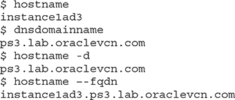
The hostname command returns the instance’s hostname, instancelad3, while both the dnsdomain and hostname -d commands return the domain name ps3.lab.oraclevcn.com. The DNS search domain lab.oraclevcn.com provided to the VCN in this compartment by the DHCP options is appended to the ps3 DNS label provided when the subnet was created.
Three of the configuration files that influence how DNS resolution works on a Linux client are /etc/resolv.conf, /etc/nsswitch.conf, and /etc/hosts. Consider the extracts from these files:

This /etc/hosts file contains the localhost loopback IPv4 address 127.0.0.1 and IPv6 address ::1. It also lists the private IP address 10.0.6.2, allocated from the subnet ps3, as well as the FQDN and hostname (in any order).

This /etc/resolv.conf file specifies the DNS search domains lab.oraclevnc.com and ps3.lab.oraclevcn.com, as well as the nameserver IP address 169.254.169.254.

This /etc/nsswitch.conf file specifies the DNS resolution order, which in this case is to resolve the target hostname by first looking in local files such as /etc/hosts and, if unsuccessful, to query the DNS nameserver listed in /etc/resolv.conf. The IP addresses configured on this instance may be queried on Linux using the ip address command:
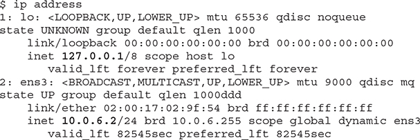
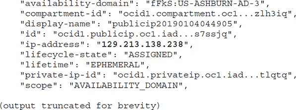
This shows the localhost loopback IP as well as the private IP. Remember that there is an ephemeral public IP associated with this private IP, although it is not shown by the OS ip addr command. You may obtain the public IP address with the following OCI CLI command using the OCID of the private IP object.

Consider the output from the nslookup command (available in most Linux and Windows distributions) as it performs various nameserver lookups:

The nslookup command queries the name server specified in /etc/resolv.conf and returns the IP address 10.0.6.2. The message indicating that this is a non-authoritative answer means that the DNS server that resolved the lookup request is not the DNS server that manages the zone file where the primary DNS record is defined. Rather, it was satisfied by another nameserver that recognized the hostname from its lookup cache and returned the matching IP address.
By querying an IP address, the nslookup command is smart enough to understand that you are requesting a reverse DNS lookup. It is similar to looking up an owner of a telephone number in a directory service to identify the account holder. In this case, the reverse DNS lookup of the private IP address 10.0.6.2 returns the FQDN instance1ad3.ps3.lab.oraclevcn.com.

Finally, querying a nonexistent name with nslookup yields the message that this domain cannot be found.

Creating and Managing DNS Records
A DNS zone stores DNS records for a DNS domain. OCI offers a DNS service, which is useful for many scenarios including the following:
• Exposing domains and zones via the Internet for DNS resolution
• Resolving DNS queries for domains and zones that reside in on-premises, OCI, and other third-party hosted environments by centralizing DNS management
• Providing a predictable, reliable, and secure DNS resolution for global DNS queries
The OCI DNS service is highly available, performant, and secure, and includes built-in security measures, such as protection against Distributed Denial of Services (DDoS) attacks. The service uses a network routing methodology well suited to cloud vendors known as anycast, which supports multiple routing paths to multiple endpoint destinations for a single destination address. This routing scheme calculates the shortest and most efficient path for a network packet to traverse, which is key when consumers may be located anywhere in the world. DNS services are part of the Networking Edge services that reduce network traffic while serving a global audience by providing DNS services at edge locations, close to where end users access OCI services.
The DNS services allow you to manage your corporate DNS records, which are domain names mapped to IP addresses for both on-premises and cloud resources. The OCI console provides access to the DNS services by navigating to Networking | DNS Zone Management, as shown in Figure 3-9.

Figure 3-9 DNS zone management
When you create a DNS zone, you may choose to manually define resource records or to import these from an existing zone file in a compatible format. RFCs 1034 and 1035 from the IETF describe Concepts and Facilities as well as Implementation and Specification of domain names respectively. A valid zone file must be in RFC 1035 master file format as exported by the BIND method. A DNS zone typically comprises either a primary zone that controls modification of the master zone file or a secondary zone that hosts a read-only zone file copy that is kept in sync with the primary DNS server.
DNS Record Types
A DNS zone contains a set of resource records (RRs) for each domain being administered. Resource records are divided into various record types. The data held in each RR is called record data or RDATA. Resource records have the following components:
• NAME An owner name or the name of the node to which this RR pertains.
• TYPE The RR type code.
• CLASS The RR class code.
• TTL The time to live interval specifies the time interval that an RR may be cached before the authoritative name server is consulted.
• RDLENGTH Specifies the length of the RDATA field.
• RDATA The resource data, the format of which varies based on TYPE and CLASS.
Table 3-3 lists a subset of the RR types available for you to define for a domain being managed through the OCI DNS services. Detailed information about the various RRs may be located by consulting the RFCs adjacent to the description in the table.
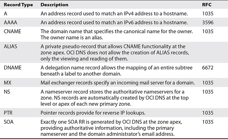
Table 3-3 Common DNS Resource Record Types
Exercise 3-7: Set Up a DNS Zone and Resource Records
In this exercise, you will set up a DNS zone and create several resource records. You may want to import an existing bind-compatible zone file or use a different domain name that is meaningful in your organization. Existing domain names cannot be used or you receive the message, “Authorization failed or requested resource already exists.” The DNS zone management in this exercise is completed using the OCI console.
1. Sign in to the OCI console.
2. Navigate to Networking | DNS Zone Management and select Create Zone. Explore the Method drop-down list, which varies between Manual or Import. Choose Manual. The zone type may be Primary or Secondary (for high availability). Choose Primary. Provide a zone name in the form <your-domain-name>, and select Submit.

3. The OCI DNS server creates a new DNS primary zone and autogenerates several NS and exactly one SOA record.
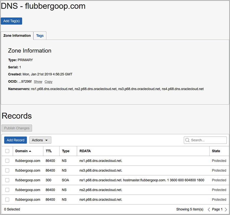
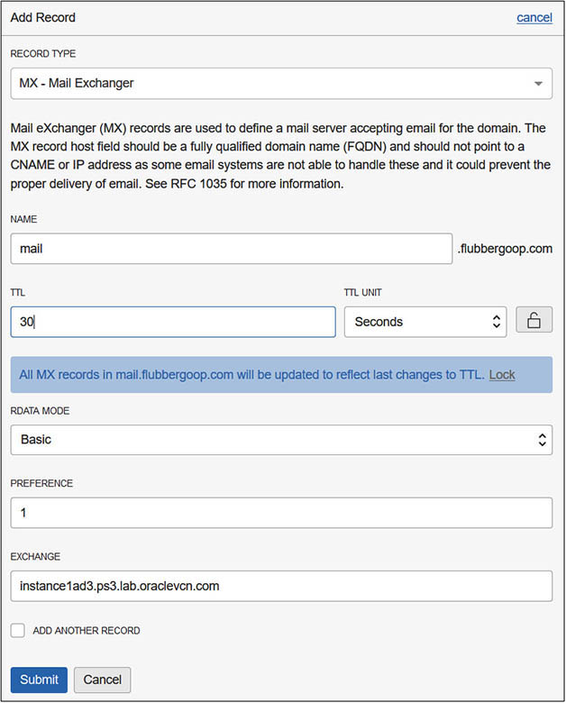
4. Navigate to the new DNS zone and choose Add Record to add a mail exchange record to handle incoming mail to this domain. Choose Record Type MX – Mail Exchanger and provide a domain name in the form <mail.your-domain-name> in the Name field. Choose the Lock icon and enter 30 seconds as the TTL value. Choose Basic mode for the RDATA. Enter 1 for the Preference field. Valid values for the Preference field is any 16-bit integer, and the field specifies the priority given to this RR among others at the same owner. Finally, specify the FQDN of the host running a mail server and select Submit.
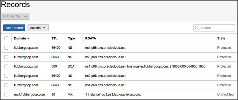
5. Notice the extra record added to the zone. To add your new MX record to the OCI DNS service, choose Publish Changes. The new MX record is now available for DNS lookup to any device using the OCI DNS service for name resolution.
Load Balancers in OCI
A load balancer is a network device that accepts incoming traffic and distributes it to one or more backend compute instances. Load balancers are commonly used for optimizing the utilization of backend resources as well as to provide scaling and high availability.
Load Balancer Terminology and Concepts
A load balancer may be public or private and is defined based on a shape that determines its network throughput capacity. When creating an OCI load balancer, you provide a name, select a shape, and choose the visibility type, either public or private. Figure 3-10 shows the specification of a public load balancer named LB1, which can support up to 100 Mbps of throughput. At the time of this writing, the available load balancer shapes include 100 Mbps, 400 Mbps, and 8000 Mbps.

Figure 3-10 Load balancer visibility and shape
Public and Private Load Balancers
A load balancer accepts incoming TCP or HTTP network traffic on a single IP address and distributes it to a backend set that comprises one or more compute instances. In this context, the compute instances are known as backend servers. Each of these compute instances resides in either a public or private subnet. When a private load balancer is created in a compartment, you specify the VCN and private subnet to which it belongs. Figure 3-11 shows an active (primary) private load balancer that obtains a private IP address from the CIDR range of the private subnet S1.
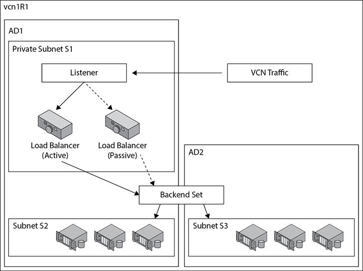
Figure 3-11 Private load balancer
A passive (standby) private load balancer is created automatically for failover purposes and also receives a private IP address from the same subnet. A floating private IP address serves as a highly available address of the load balancer. The active and passive private load balancers are highly available within a single AD. If the primary load balancer fails, the listener directs traffic to the standby load balancer and availability is maintained. Security list rules permitting, a private load balancer is accessible from instances within the VCN where the subnet of the load balancer resides.
Public Load Balancer
A public load balancer is allocated a public IP address that is routable from the Internet. Figure 3-12 shows the active (primary) public load balancer in subnet S1 in AD1 in vcn1R1.
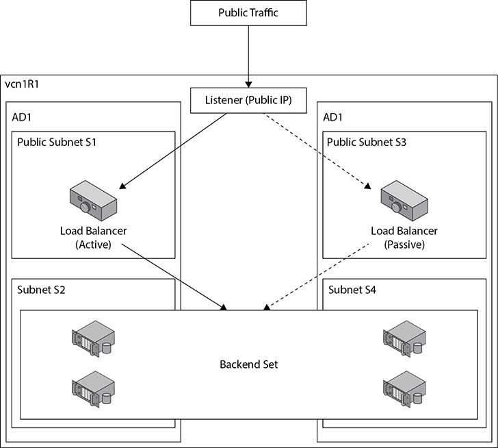
Figure 3-12 Public load balancer
Incoming traffic from the public Internet on allowed ports and protocols is directed to the floating public IP address associated with the active load balancer. If the load balancer in subnet S1 fails, the passive device in subnet S3 is automatically made active.
The public load balancer is a regional resource as opposed to a private load balancer, which is an AD-level resource. In regions with multiple ADs, it is mandatory to specify public subnets in different ADs for the active and passive load balancers. Figure 3-13 shows a load balancer in the Phoenix region being defined. This region has multiple ADs. Two subnets in different ADs must be chosen.

Figure 3-13 Failover accessibility for a public load balancer
Listener
At least one listener is created for each load balancer, and as of this writing, up to 16 listeners may be created. Each listener in a load balancer defines a set of properties that include a unique combination of protocol (HTTP or TCP) and port number. Web traffic (HTTP) is also known as application layer or layer 7 (from the OSI model) traffic while TCP traffic is known as transport layer or layer 4 traffic. Figure 3-14 shows the listener properties that may be defined. At a minimum, a listener requires a protocol and a port.
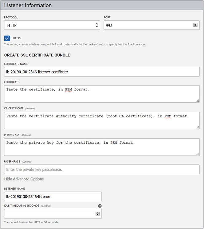
Figure 3-14 Listener information
Your load balancer can handle incoming SSL traffic if you check the Use SSL checkbox and provide the relevant certificate information. SSL traffic may be handled with the following three mechanisms:
• SSL termination SSL traffic is terminated at the load balancer. Traffic between the load balancer and the backend set is unencrypted.
• SSL tunneling Available for TCP load balancers, SSL traffic is passed through to the backend set.
• End-to-end SSL Incoming SSL traffic is terminated at the load balancer and a new SSL connection to the backend set is created.
You may also specify an idle timeout duration that will disconnect a connection if the time between two successive send or receive network I/O operations is exceeded during the HTTP request-response phase.
Once a load balancer is provisioned through the console, additional listeners may be defined as well as these additional properties that reduce the number of load balancers and listeners required:
• Hostname or virtual hostname You define this property and assign to an HTTP or HTTPS (SSL enabled) listener. As of this writing, up to 16 virtual hostnames may be assigned to a listener and often correspond to application names. Hostnames may also be backed by DNS that resolve to the load balancer IP address.
• Path Route Rules Used to route HTTP traffic to different backend sets based on matching the URL pattern in an incoming request. For example, requests with the pattern /login may be routed to the identity management backend set while requests with the pattern /apex may be routed to the application server backend set.
• Rule sets Defined at the load balancer level and may be used by multiple listeners of the load balancer. Rule sets add, alter, or remove incoming HTTP request headers. Examples of how rule sets enhance security include stripping debug headers from requests and preventing external domains from embedding your site in an iframe. Backend servers may also be notified of SSL termination by adding application-specific information to a request header at the load balancer listener.
Backend Set
A load balancer is a network device that ultimately routes traffic to one or more reachable backend compute instances (called backend servers) that reside in any subnet in the VCN. A backend set is a logical grouping of backend servers and a traffic distribution policy. Figure 3-15 shows a backend set with two compute instances (webserver1 and webserver2) and their compartments, IP addresses, local listening ports (which may be different from the load balancer listener port), and a weight. It is good practice to spread backend set instances across multiple ADs to support high availability.
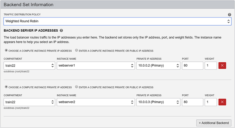
Figure 3-15 Backend set information
You choose a traffic distribution policy and the compute instances that comprise the backend set. Additional properties of a backend set include the following:
• Configuring a Health Check that determines the status of backend compute instances and their eligibility to accept incoming requests.
• Choosing whether SSL is to be used between the load balancer and backend instances.
• Enabling session persistence, also known as stickiness, to route traffic from a single client to a specific backend instance when multiple requests are made, such as in the context of a shopping cart application running on a website. This option provides support for cookies.
TCP and non-sticky HTTP incoming traffic is distributed to the compute instances in a backend set based on the instance’s weight and traffic distribution policies. Cookie-based persistent HTTP requests additionally forward the cookie’s session information. The three traffic distribution policies are
• Weighted Round Robin The default policy. Allocates connections to backend servers in a sequential manner based on the weight fields. Traffic to the load balancer front-ends the backend set with webserver1 and webserver2 in Figure 3-15 will be evenly distributed because each instance has an identical weight. If the weight of webserver1 was updated to 2, it would receive two requests for every one request that was sent to webserver2.
• IP Hash Applies a hashing function to the IP address of the incoming request to route non-sticky traffic to the same backend server.
• Least Connections Routes non-sticky incoming requests to the backend instance with the least active connections.
The Health Check API caters to four health status values including OK, warning, critical, or unknown. Figure 3-16 shows an HTTP health check on port 80 that connects to each of the instances in the backend set every 100000 milliseconds. HTTP works with request and response pairs. An HTTP request is made from the load balancer to an HTTP listener on a compute instance, which replies with an HTTP response. The response contains a status code like 200, which means OK, as well as an HTTP response body, which may be evaluated using a regular expression to identify success or potential problems with the backend instances. You can specify the number of retries the health check attempts before flagging a problem with a backend instance.
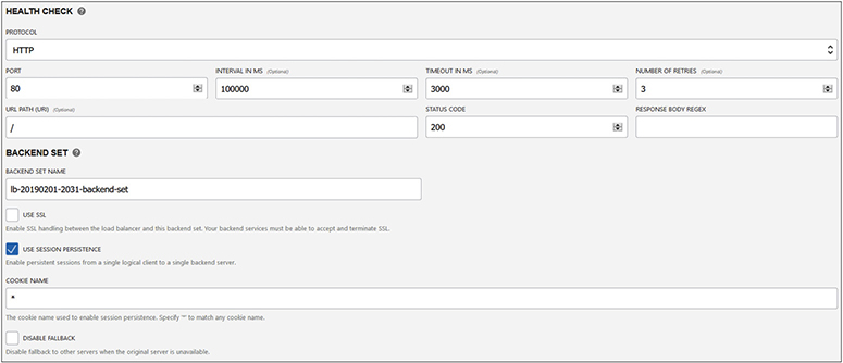
Figure 3-16 Load balancer health check
Exercise 3-8: Set Up a Load Balancer
In this exercise, you will set up a public load balancer with a backend set with no compute instances. In Chapter 4, you will create several compute instances and add some of these to the backend set in a new load balancer.
1. Sign in to the OCI console.
2. Navigate to Networking – Load Balancers, choose a compartment, and select Create Load Balancer. Explore the Shape drop-down list, which varies between 100 Mbps, 400 Mbps, and 8000 Mbps. Choose 100 Mbps. Provide a name, such as public-lb1, and choose the visibility type to be public.
3. The Network Information section may display multiple subnets or a single subnet depending on the number of ADs in your region. Choose a VCN and one or two public subnets.
4. Choose HTTP as the protocol and port 80 in the Listener Information section. Expand the Advanced Options and specify a listener name, such as public-lb1-listener, and update the idle timeout to 30 seconds.
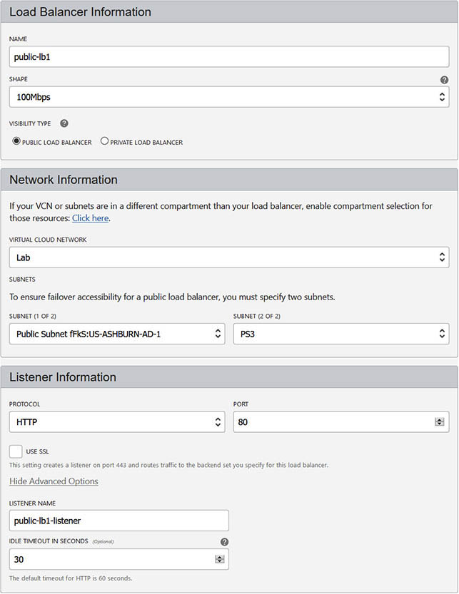
5. Choose Weighted Round Robin as the traffic distribution policy. Expand the Advanced Options to configure the Health Check. Update the URL path to /healthcheck.html and provide a name for the backend set, such as public-lb1-backendset, and choose Create. On each backend compute instance, you may now define a customized healthcheck.html file to respond to health check requests from the load balancer.
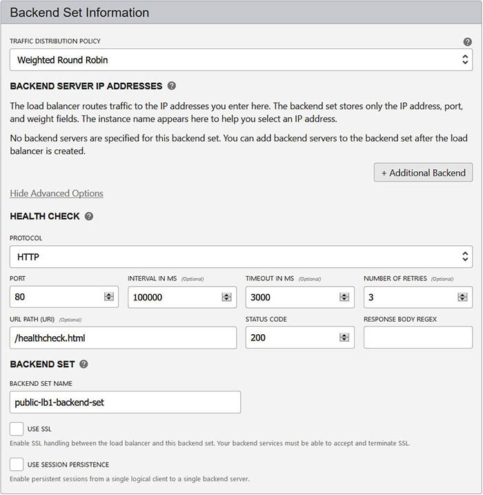
6. After a few minutes, a public load balancer is provisioned with an ephemeral floating public IP address.
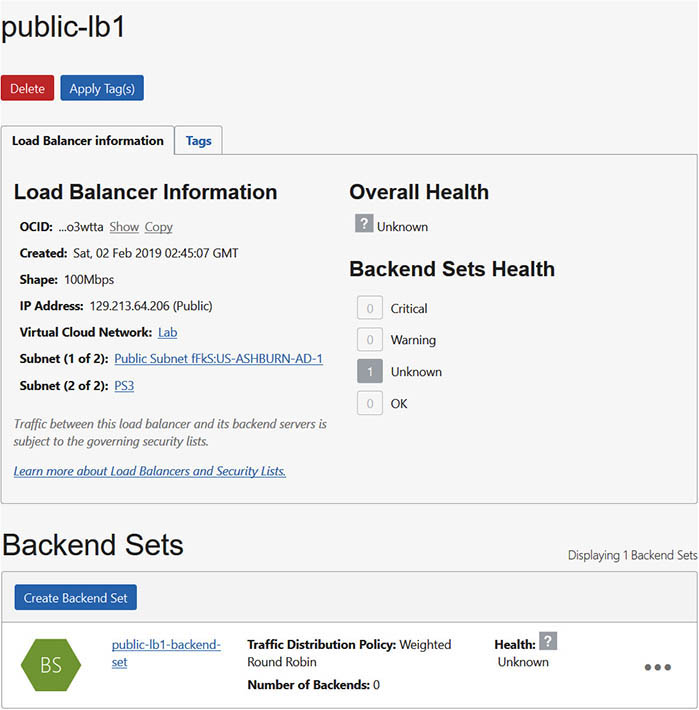
Design and Secure OCI Networks
This section reviews the interaction between key VCN components and discusses best practices for VCN design and edge security.
VCN Design
A VCN is allocated an unmodifiable contiguous IPv4 CIDR range from /16 to /30, so when designing VCNs, ensure that the range is sufficiently large. Many customers use VCNs with a /16 netmask and subnets with /24 netmasks, primarily selecting smaller VCNs and subnet ranges to avoid overlapping with existing networks. This is also the default VCN and subnet sizing provided when you create a VCN plus related resources through the console. A VCN spans all ADs in a region and may contain subnets in any AD in the region. Regional subnets allow for a subnet to span all ADs in a region and may simplify your design. You may, however, want to use AD-specific subnets to isolate networks by AD in a multi-AD region.
The CIDR range of each subnet in a VCN uses a subset of the VCN’s CIDR block. Common considerations when sizing subnets include ensuring there is sufficient room for growth. You may have 100 compute instances today, but design with future growth in mind. Instance pools and autoscaling, discussed in Chapter 4, may lead to an explosion of IP addresses required in a subnet. The balance to strike is to provide sufficient room for future growth within both the subnet and the VCN. Table 3-4 provides an example frame of reference for VCN and subnet sizing. Remember that the first two IPs and the last IP in each subnet’s CIDR are reserved.

Table 3-4 VCN and Subnet Sizing Frame of Reference
A simplistic way to interpret the default sizing in Table 3-4 is as follows. The VCN CIDR netmask is /16, allowing a maximum range size of 65,488 IP addresses. If all subnets in this VCN are created with a /24 netmask, each will support 256–3 = 253 IP addresses. Segmenting or dividing 65,488 IP addresses into blocks of 253 IPs equates to 258 subnets. There is a service limit of 300 subnets per VCN.
To summarize, when designing your VCN and subnet sizing, consider the following:
• Segregating CIDR blocks of your on-premises and cloud networks to avoid overlapping subnets in case you want to set up peering between these networks.
• Dividing your VCN CIDR evenly across all ADs in the region into n+1 blocks where n is the number of ADs in your region, keeping one block for future expansion.
• Whether you are likely to need larger ranges for private subnets rather than public subnets and partition accordingly.
Architecting for high availability is discussed in Chapter 8, but when designing VCNs, try to maximize the use of multiple ADs for high-availability and to make use of fault domains in single AD regions.
Edge Security
When designing security for your VCN, many OCI networking components are available out of the box to support good practice, starting with private and public subnets. It is usually permissible to expose a public load balancer to the Internet for HTTP traffic to your public website or web applications. These points of entry need to be secured and protected. Sensitive databases should be located in private subnets. NAT gateways may be used for instances in private networks to gain one-way access to Internet resources and still be protected. Use the route table infrastructure to ensure that Dynamic Routing Gateways only route allowed traffic between your VCN and your on-premises network or other cloud networks.
Each subnet can have one route table comprising rules that route traffic to one or more targets. It is good practice for hosts that have similar routing requirements to use the same route tables across multiple ADs. It is also recommended that private subnets have individual route tables to control traffic flow. Traffic between all compute instances within a VCN is routable but the VCN route table limits routing of traffic into and out of the VCN.
Each subnet may have multiple security lists (up to a hard limit of 5, as of this writing), each of which supports multiple stateful and stateless ingress and egress rules. You must ensure that security lists behave like firewalls, managing traffic into and out of the VCN (known as North–South traffic) as well as managing internal VCN traffic between multiple subnets (known as East–West traffic).
Oracle also recommends the use of OCI IAM policies to allow only authorized groups of users to manage VCN resources. As with all security policies, it is usually best to provide the minimum set of privileges to groups.
Chapter Review
Understanding OCI networking is a fundamental skill for architecting and securing your OCI environment. This chapter explored the relationship between many generic networking concepts. Many on-premises physical network components are virtualized in OCI but are essentially functionally equivalent. This chapter assumed no prior networking experience, explaining CIDR blocks before introducing virtual cloud networks. The speed at which you can provision a VCN and create subnets, route tables, and security lists is astonishing in OCI. A detailed discussion of subnets, both public and private, ensued by defining how public and private IP objects are assigned to vNICs from your subnets.
Internet gateways extend your VCN by providing Internet access to public subnets while NAT gateways provide a mechanism for instances in private subnets to access the Internet. Service gateways extend the reach of instances in your VCN to other OCI services, notably object storage, without needing to route traffic through the DRG. Local peering gateways link up VCNs in the same region, while remote peering across regions is facilitated by running a remote peering connection through your DRG.
We turned our focus to the DNS edge services as well as how to create and manage DNS records and zones. The chapter explored private and public load balancers and explained the underlying listeners, backend sets, path route rules, and rule sets. The chapter closed with a discussion of best practices when designing VCNs and sizing subnets as well as considerations for edge security. With your VCN and subnets in place, you are ready to start creating compute instances, the subject of Chapter 4.
Questions
1. Choose the CIDR range with the largest IP address block?
A. 192.168.1.1/30
B. 192.168.1.1/255
C. 10.1.0.0/16
D. 255.255.255.0
2. Which statement regarding the scope of a VCN is true?
A. A VCN is a regional construct.
B. A VCN is a global construct.
C. A VCN is an AD-level construct.
D. All of the above.
3. Which of the following network components facilitates access to the Internet?
A. Local peering gateway
B. Service gateway
C. Internet gateway
D. Remote peering connection
4. Which set of prerequisites must be met before an instance can be accessed from the Internet? Choose one or more options.
A. The instance must be in a public subnet.
B. The instance must be in a private subnet.
C. The route table must be configured appropriately.
D. The security list must be configured appropriately.
E. The VCN must contain a functional Internet gateway.
F. The VCN must contain a functional NAT gateway.
5. Which of the following statements is true?
A. BGP is supported with IPSec VPN but not FastConnect when connecting external networks to your VCN.
B. BGP is supported with FastConnect but not IPSec VPN when connecting external networks to your VCN.
C. BGP is supported with FastConnect but not IPSec VPN when connecting subnets within your VCN.
D. BGP is supported with IPSec VPN but not FastConnect when connecting subnets within your VCN.
6. How many IP addresses does a private load balancer require?
A. One
B. Two
C. Three
D. Four
7. A VCN is defined with the CIDR 192.168.0.0/30. How many IP addresses from this CIDR block are reserved by OCI?
A. 1
B. 2
C. 3
D. 4
8. A VCN is defined with the CIDR 192.168.0.0/30. How many IP addresses from this CIDR block are available for host addresses?
A. 1
B. 30
C. 192
D. 168
9. Which protocols are supported by OCI load balancers?
A. HTTP/1.0, HTTP/1.1, HTTP/2.0
B. HTTP/1.0, HTTP/1.1, HTTP/2.0, TCP
C. WebSocket, HTTP/1.0, HTTP/1.1, HTTP/2.0, TCP
D. WebSocks, TCP, HTTPS
E. WebSocks, SSL, TCP, HTTP
10. Which are three load balancer traffic distribution policies?
A. Weighted Round Robin, IP Hash, Coin Toss
B. Weighted Round Robin, IP Hash, Random
C. Round Robin, Coin Toss, Most Connections
D. Weighted Round Robin, IP Hash, Least Connections
Answers
1. C. The lower the netmask in the CIDR notation, the larger the addressable IP range.
2. A. A VCN spans all ADs in a region and is therefore a regional construct.
3. C. An Internet gateway is required to facilitate Internet access in a VCN.
4. A, C, D, E. Several prerequisites must be met before an instance can connect to the Internet. The subnet it is created in must be a public subnet, with appropriately configured route tables and security lists, located in a VCN with an Internet gateway.
5. B. BGP is supported with FastConnect but not IPSec VPN when connecting external networks to your VCN.
6. C. A private load balancer requires three IP addresses from the associated subnet for the primary and standby load balancers as well as the floating private IP.
7. C. OCI networking service reserves the first IP known as the network address, the last IP known as the broadcast address, as well as the first host address in the CIDR range known as the subnet default gateway address.
8. A. This CIDR block specifies four IPs: 192.168.0.0–192.168.0.3. After OCI networking services takes the three it requires, only one remains for host addressing.
9. C. OCI load balancers support many protocols, including TCP, HTTP/1.0, HTTP/1.1, HTTP/2.0, and WebSocket.
10. D. The three traffic distribution policies available for load balancers are Weighted Round Robin, IP Hash, and Least Connections.


