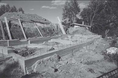
LIKE ALL FOUNDATIONS, the main purpose of the foundation under a cold-climate bale building is to carry the loads of the roof and walls down to stable, frost-free soil. On many sites, the ideal foundation will also serve a second function: It will isolate the bales (and any wooden framing members) from the deleterious effects of damp ground and rainwater splashing back up off the ground, against the walls.
Soil can freeze at depths varying from a few inches to many feet, depending on climatic conditions. Pressures as high as 19 tons per square foot (1,820 kiloPascals) have been registered from freezing soils, in one case raising a raft foundation (a specialized floating slab used in commercial construction) under a seven-story building a total of 2 inches in one season!1 Frost-related heaving will result from the conjunction of three conditions: soil must be capable of holding water, water content of the soil must be sufficient, and temperatures must be low enough to induce soil and water to freeze. Lacking any one of these three conditions, ground heave will not happen.
Most foundations work by extending down to naturally frost-free soil, or to solid rock. This is an obvious choice if you want a basement, but in other situations, it can be unnecessarily expensive. The rubble trench and grade beam works by allowing water to drain out from below the foundation so that it cannot freeze in place and heave. An increasingly popular third choice is to temper the soil below the house, so that it never gets cold enough to freeze. Such is the premise behind the shallow, frost-protected foundation. As we look at foundation options through this chapter, we’ll consider these various approaches to avoiding ground movement, while also explaining moisture control and the suitability of a given option to bale construction.

Shallow foundations will not move if resting on solid rock.
Foundation Walls,
Basements, and Bales
When you move into a house with a full cellar, you pretty much move into a house, workshop, and storage space all at the same time. A basement is the ultimate in what Stuart Brand calls “low road”2 spaces: areas of a building that are so utilitarian that it really doesn’t matter what you do in them. They are supremely flexible spaces, to which every layer of use adds character. We’ve seen basements used as workshops and offices, as play rooms for kids and ex-ercise rooms for their parents, as a space to relegate the TV, as an extra bedroom, in a pinch, and (yes, Paul really did see this) as a place to throw the garbage. Basements in farmhouses have historically been used for food storage. In Quebec, it was once common to find sheep and pigs housed sheep and pthrough the winter in a basement. In the days before the central furnace, they probably served to keep the rooms above from freezing.
Advantages of Basements
Basements hold three great advantages for bale builders. First, and most important, they offer a simple way to pick up the bales away from the ground. Second, they provide a place to run utilities. Third, they serve as a warm, dry place to store tools and materials during construction.
ELEVATE THOSE BALES!
On some sites and with some roof configurations, splashback and direct rain can cause periodic wetting of the lower portions of the walls. One of the simplest steps you can take toward keeping your bale walls dry is to elevate them above these ground sources of moisture. In such cases, basement walls are typically brought up one to two feet above finished grade, and sometimes higher, if the basement is to have some real windows and eventually end up as a finished space. The floor framing system, plus a toeup for the bales, will add another foot or so of separation between the straw and the ground, for a total of two to three feet. In situations where harmful moisture sources are an issue, this should be sufficient distance to isolate them from the straw.
Why
Do I
Need a
Strong
Foundation?
Foundations serve the same function in every building—they anchor the building to the ground. The taller the building and the colder the climate, the more crucial this function becomes. Tall buildings require a firm foundation for fairly obvious reasons: The effects of wind and earthquakes are amplified by height, and the more stories you stack on top of each other, the more weight is concentrated at one point on the ground, increasing the per-square-foot workload of the foundation and the soil upon which it bears.
If tall buildings need strong foundations because they spend their lives conducting kinetic energy (wind) out of the air and into the ground, then it could be said that cold-climate buildings need strong foundations for exactly the opposite reason. In cold climates, the ground cannot be trusted to stay still. Each time wet soil is subjected to below-freezing temperatures, the water held in it freezes, and expands. This happens every winter, to some degree, the total depth of frost being determined by a combination of temperature and snow cover. Cold temperatures freeze soil, snow insulates. It is not uncommon to dig through three feet of snow and find thawed soil underneath. During a cold and open winter, on the other hand, soil can freeze to four or five feet of depth at the U.S./Canadian border, and deeper farther north.
When the water in the soil freezes, it expands. Expanding water needs more space, and the direction in which space is to be found, as any astronomer will tell you, is up. Anything in the way of this expansion will be carried right along, that is, will be pushed up. The rock farmer, therefore, has chosen an effortless profession: He simply waits for each winter’s freeze to push up some more rocks!
Your house, ponderous though it may seem, is really no different from a rock. Its weight is much less than the force of expanding water, pushing skyward. If the frost were simply to increase the elevation of your home by an annual increment, no harm would really be done, especially as the local shrubbery could be expected to grow at a better than equivalent rate. The problem is that frost can be counted on to push unevenly against the underside of your building, resulting, before long, in cracked foundation walls, cracked plaster, windows that don’t open, water in the basement, and the rest of the litany of structural problems that have plagued homeowners since the dawn of the permanent dwelling (not all that long ago, mind you). This is why cheap bale houses on minimal foundations, which are not inappropriate in desert settings, are usually not a good idea in cold climates.
UTILITIES
Basements provide an ideal location for a building’s mechanical room. The space and hotwater heating equipment, if located in a basement, need not compete with the domestic functions of the home for valuable floor area within the living space. Basements also offer a space in which to run pipes, electrical and telephone wires, ducts, speaker, television, and computer cables, and any other accessory of postmodern living that you or your descendants may dream up. Electrical wires can be run in the basement and stubbed up into your bale walls, making future modifications to the electrical system relatively simple. Basements also do not usually freeze, which is an excellent quality in a space that will house pipes. A building’s entire mechanical system, from delivery through appliances and back through return lines, can be left visible in a basement, with no effect on the aesthetic qualities of the spaces above. A basement is basically a giant chase, with the added benefit that you only need look up in order to see where everything is. This is the type of arrangement that remodelers dream about.
STORAGE DURING CONSTRUCTION
Basements offer a dry place to store bales, plaster ingredients, and other moisture-sensitive materials. A basement is not necessarily the ideal place for such storage, because the materials must be lugged upstairs before they can be used; but in a situation where a house is to be built slowly or in stages, the flexibility offered by a dry, relatively secure space for tools and storage more than offsets the hassle of having to haul things up and down the stairs.
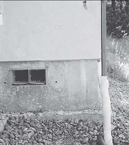
Graded stone and piping can ensure that water drains from below a foundation, so water will not freeze in place and heave.
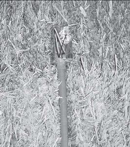
Electrical wires can be run in the basement, and stubbed up in conduit into the bale walls.
Moisture Control with Basements
When we talk about basements as useful spaces, by no means are we talking about damp, smelly caves ruled by trolls whose eyes would be put out by the light of day. Useful basements are dry basements (and, ideally, partially daylit basements).
Moisture appears in basements by three processes: bulk leakage from groundwater sources, wicking through capillary pores in concrete, and vapor migration from both interior air and exterior soil. (See chapter 2, “Design Challenges,” for definitions of these terms.) Each of these sources must be dealt with, if basement walls are to be kept dry.
LEAKAGE
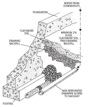
Bulk leakage is best avoided by keeping standing water away from foundation walls. Backfill material should be free draining, composed of gravel or coarse sand. A perforated drainpipe should be located at the perimeter of the foundation footing; this should be surrounded by a coarse gravel, and the gravel layer should be wrapped top, sides, and bottom with filter fabric, to keep fine material from migrating in, clogging the pores of the gravel, and eventually blocking the pipe. The pipe should be sloped to daylight. Ideally, this whole array should be covered by a relatively impermeable, clay-based soil, with a slope of at least five percent away from the building (see diagram at right).
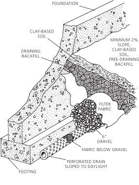
Foundation drain.
Gutter drain.
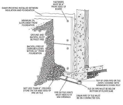
Roxul Drainboard system.
Roof gutters should not be run into the foundation drainpipe. The net effect of this practice is to dump all of the water that comes off the roof directly at the base of the foundation wall, the exact area from which the gutters are supposed to divert it. Gutters should either be run into extended downspouts, which carry the water a minimum of four feet away from the building, or into a separate set of below-grade, nonperforated pipes, and then run out to daylight, alongside the foundation drainpipe.
Straw bale builders in Canada and the United States are lucky to have available a product called Roxul Drainboard; Canadians also have access to RXL panels. Roxul is a rigid mineral wool (reprocessed slag) that possesses a remarkable pair of qualities for foundation builders: an Rvalue of 3.5 per inch for the Drainboard (available in 1- to 4-inch thicknesses) and as much as 4.08 per inch for RXL 80 (thicknesses of 1 to 5 inches), combined with the ability, due to the orientation of the mineral fibers, to drain water freely. Even after being soaked, these boards dry out and keep their insulation value. (A report in the magazine Innovation [winter 1999, vol. 4, no 2] by the Canadian National Research Council on tests of foundations insulated on their exterior with this type of insulation proves that their thermal properties are not affected by water exposure.) Roxul boards used as exterior foundation insulation should be flashed top and bottom, to keep rainwater from running into the top, and to direct water running out the bottom away from the footing, toward the foundation drainpipe. In Canada, Roxul Drainboard is less expensive than extruded polystyrene insulation; it can also save on fill costs, as it can be backfilled with native soil (though a proper foundation drain system is still required).
Stay-in-place foam forming systems (discussed later in this chapter) typically employ a tough, bituminous waterproof membrane on the exterior of below-grade walls. Such a layer blocks moisture entry by all three transport mechanisms (bulk leakage, capillarity, and vapor migration). At roughly 75 cents U.S. per square foot, however, such a layer is rather expensive, especially where it is serving as backup to a free-draining backfill. Many other self-adhesive or torched-on membranes made of modified bitumen, PVC, or EPDM are also appropriate for those who are looking for a fast and easy job, or are in a risky situation and ready to pay a little more.
CAPILLARITY
Capillary wicking in basement walls is typically controlled by rolling on a dampproofing layer of black bituminous liquid, which fills the capillary pores on the surface of the concrete. An alternate method, employed for years by Todd Osman of Gays Mills, Wisconsin, uses bentonite clay. Bentonite expands dramatically in contact with water, increasing to as much as nineteen times its dry volume at full saturation. (If your cat litter is of the swelling type, chances are it’s made of bentonite clay.) It is used for lining irrigation ditches, and also by well drillers as a combination lubricator/sealant. It is often available from well-drilling companies.
Todd’s method is to mix the bentonite with water until it reaches a trowelable, gelatin-like consistency. He then spreads it over the wall, followed by a sheet of 6-mil polyethylene. (Some builders of underground houses will sandwich the plastic sheet between two thin coats of bentonite plaster.) The bentonite takes on any water that makes its way through or around the porous backfill and plastic layers, presumably swelling to fill the capillary pores in the concrete, in the process. An added benefit of this method is that it should work as a gasket-like seal over any small cracks that might appear in the foundation wall over time. Composite bentonite/ geotextile membranes are also available on the market; these are used for foundation waterproofing in large commercial structures, but would be equally appropriate in houses.
VAPOR
The dampproofing layer, be it bituminous or membrane or bentonite and plastic, should also serve as an effective barrier against vapor diffusing into the foundation from the soil. The more pressing issue here is condensation of vapor from interior air, on the surface of or at some point within the depth of the foundation wall. This phenomenon is prevented by one of two insulation strategies.
The basement wall can be insulated on its outside, thus raising the temperature of the wall to the same as that of the interior air, and thereby removing the dewpoint from the wall to some location in the backfill soil (see diagrams). This method offers the benefit of turning the entire concrete wall into a substantial thermal storage medium. Foam-formed walls work on the same principle.
Alternately, the wall might be insulated on the interior, and detailed as if it were an exterior wall, with a continuous poly air/vapor barrier behind the drywall. Airtight drywall finished with a vapor-barrier paint would also be an option. It is not a bad idea, in the case of interior insulation, to also dampproof the interior surface of the foundation wall. Even though such a layer is outside the air barrier envelope of the building, it is still safest to avoid the use of any material that might adversely affect the air quality inside the building. A vapor-retardant paint would be a better choice than foundation sealer here, though you must make sure it is capable of adhering to concrete (see diagram).
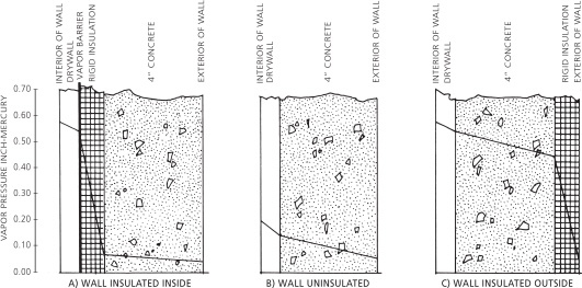
The vapor pressure inside a wall is related to the location of insulation. Adapted from J. K. Latta, Murs, fenetres ^ et toitures pour le climat canadien (Ottawa: Division des recherches sur le batiment,^1975: p. 71).
The interior surface of bale-insulated foundation walls (see “Foundation Walls,” below) should be treated with a vapor-retardant paint. Unlike in above-grade walls, any small amount of vapor that does make its way into the bale core of the wall will have no way of escaping to the exterior, because this surface will have been sealed against ground moisture entry. The best strategy, in this case, is to detail the wall as carefully as possible to exclude all potential sources of moisture.
BASEMENT FLOOR SLABS
All of the same concerns that apply to basement walls apply to basement floors. Because floors are often detailed less carefully than walls, they typically tend to contribute a disproportionate share of moisture to basements. Basement slabs should be detailed exactly like concrete floor slabs. (See “Concrete Slabs” below for more information.)
Builders on a tight budget are often tempted to cut corners on the basement floor insulation, especially in situations where the basement is not expected to be incorporated into the living space. Except in a very dry climate, this is a serious mistake, which can ultimately saddle the owner with a choice between running a dehumidifier or accepting a damp basement. It also effectively rules out the possibility of using the basement floor as the floor of a finished living space, because it will always be cooler than the basement air, and thus a surface that collects dampness. In order to safely finish such a space, without risk of unhealthy molds in area rugs or other floor coverings, the prospective remodeler would need to fur up with framing lumber and insulation, and install a second floor. As headroom tends to be at a premium in a basement, such a solution would often not be practical.
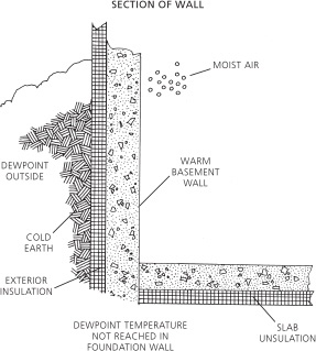
Dewpoint for exterior-insulated basement walls.

Typical foundation with interior insulation.
TOE-UPS
If your bales are to sit upon the floor of the building—that is, unless your bale walls sit atop an independent foundation wall or grade beam that is made just for them—then you must think about toeing-up the bale wall from the floor level. This will certainly be the case in a bale house over a basement, where the bale walls will sit upon a framed floor, which rests on the basement walls. The purpose of this toeup (typically 1 1/2 to 2 inches) is to protect the bales from inundation, either during the construction process, or if ever the plumbing in the house explodes. (See “Concrete Slabs” below for more information.)
Foundation Walls
Most people, when they think of basement walls, think of conventionally formed concrete, or concrete blocks. While these two systems do account for the vast majority of basement walls, some alternative systems merit attention. Because these alternatives tend to be wider than standard foundation walls, they can also be useful in situations where, within the same story, a transition must be made from a below-grade wall to a bale wall.
STAY-IN-PLACE FORMING SYSTEMS
Stay-in-place foam forming systems, now available almost everywhere, can be used to advantage in bale houses. Various manufacturers have each developed their own twist, but the basic idea is a simple one. Hollow blocks of rigid foam (or, in some cases, sheets of foam held six to ten inches apart by plastic spacers) are stacked like giant Legos, creating a freestanding foam wall with an empty center. Rebar is added as necessary, typically snapping into chairs molded into the spacer component of the blocks. The entire cavity is then poured solid with concrete, the exterior sealed with a waterproof membrane, and, presto! you have a basement wall that is insulated to somewhere between R-25 and R-35.
These forms do have a few disadvantages. They’re somewhat expensive, though they allow the owner-builder or small contractor to do his or her own formwork, with a minimum of purchased or rented equipment. They use a lot of foam, and foam is not too high on the list of ecologically preferable materials. You can assume that such a forming system will use between two and three times the 2 inches of rigid insulation that is typically applied to the exterior of a foundation wall. (Of course, this also means two or three times the R-value.)
One particular brand of these forms, the Rastra block, is quite interesting. It is made from 100 percent recycled beadboard—ground up packaging material from the electronics industry—held together with cement. It is vapor permeable, yet nonabsorptive. The cores are poured in a grid pattern, rather than as a solid wall, so less concrete is needed than with most other systems (although a substantial amount of cement is used to bind the foam beads together, raising the embodied energy of the material). The widest block is 14 inches, exactly the width of a two-string bale laid on edge, and also sufficiently wide to support a three-string bale laid on edge, or a two-string bale laid flat (especially if the 4-inch overlap is held to the inside, and a wiring and plumbing chase is framed in below it).
Stay-in-place foam forming systems, now available almost everywhere, can be used to advantage in bale houses.
The manufacturer’s stated Rvalue of 3.5 per inch is somewhat difficult to believe. Still, given a margin for error, a Rastra wall should have a higher Rvalue than the typical basement wall, with its 2 inches of exterior extruded polystyrene insulation. The two major drawbacks to Rastra panels are the need for a small crane in order to install them, and the long shipping distance to any cold climate, anywhere in the world. Plants are located in Ciudad Juarez and Mexicali, Mexico, and in Las Vegas, Nevada, U.S.; transporting these panels to your site may add signifi-cantly to the cost of the product, both in terms of dollars and embodied energy.
The Faswall block is a substitute for concrete block, made of waste wood chips treated with a mineral solution, bonded with cement. As with foam-form systems, the cores are grouted solid, to create a very strong wall. Blocks measure 16 inches long, 8 inches high, and 11.5 inches wide, weigh 22 pounds, and are rated by the manufacturer at R-13. Produced in Arkansas, this product can be a good choice for Midwestern-state and prairie-province bale builders.
Both Rastra and Faswall, with their highly textured surfaces and cement component, take plaster quite nicely. This allows for a seamless visual transition from bales into foundation material.
Foam-formed basement walls have been used as a basement-wall-and-floor-support system, as in Jonathan Stevens’ and Nancy Simons’ home in Leverett, Massachusetts, and also to support bales directly, as a wrap around a post-and-beam structure. Laurie Smith, an experienced and in-ventive straw bale builder from Shelburne, Vermont, used the Blue Maxx brand of forms, which offer the option of a flared-out top course, designed to support a brick veneer. This flared foundation, including foam, finishes out at 15 1/2 inches of width, ample support for a wall of two-string bales, laid flat.
Crawlspaces
The crawlspace was a popular foundation in the days when cellar holes were dug by hand, and lined with the stones that were a product of the ex-cavation. Removing soil from an 8-foot-deep hole would have been a very different scale of operation from digging to the frost line, and since a crawlspace stores potatoes quite nicely, many settler houses, regardless of region, rest upon such a foundation. These people did not have the luxury of thinking about where they might store their Christmas decorations. Their houses also tended to suffer from such extreme ventilation that a damp crawlspace would have had little opportunity to cause moisture-related problems within the fabric of the building.
For the vast majority of buildings today, however, crawlspaces simply don’t make any sense. The problem is summed up in the name: A crawlspace is a 3- to 5-foot-deep space under your house through which you must crawl, in order to get at your pipes, wires, potatoes, or Christmas decorations. Subcontractors will curse you throughout the construction process, and you will probably curse yourself, once you realize that with a bit more excavation and concrete, you could have built a usable space under your house. Have you ever tried to set up a sewing machine or table saw in a crawlspace?
Other issues come into play, as well. Crawlspaces must be detailed like minibasements, which is what they are. You have two basic options: Either the foundation walls and floor must be insulated and the crawlspace heated somewhat, or the crawlspace ceiling (the framed floor of the main building) must be detailed like an outside wall. If the floor of the crawlspace is soil, it should be covered by a continuous sheet of polyethylene, to keep ground dampness in the ground, where it belongs. Unless you are in a very dry climate, the crawlspace should not be vented to the outdoors in summer, as venting will cause water to condense out of warm, humid air onto the cooler crawlspace floor. This is less of an issue if the floor of the main building is detailed as an outside wall; in neither case is it ideal.
Crawlspaces share with basements and piers the benefit of picking up the bales a fair distance from the ground. They do make sense in isolated situations—specifically when ledge or groundwater is close to the surface, or if you live in one of those peculiar areas of shallow frost depth (2 feet) based on the as-sumption of a snow cover through the winter, or if you want a wood-framed floor but really have no interest in a basement.
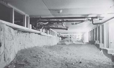
A crawl space is not usually a good foundation choice, but can be convenient and economical for a large building sitting on rock.
MICHEL’S BALE-CORE STEM WALL
Michel’s innovative system was tried experimentally on one project in Quebec, in 1994. It was intended to be used for the whole house, a six-level building on a sloping site. The first phase was a 13-by-15-foot storage and work space with two walls completely buried in the ground. A modified post-and-beam structure made of 6-by-rough-sawn hemlock posts spaced 6 feet apart topped by 6-by-6 beams was raised on a previously poured straw bale slab. Two 36-inch bales were jammed on edge in rows between the posts. They were secured together by forcing down onto their top a 1-by-2 furring strip running horizontally on each side of the posts and fastened to same. Nails were driven through the 1-by-2s into the bales to hold them firmly in place.
Flakes were then laid between the 1-by-2s and additional rows of bales were stacked and fastened the same way until the 7 1/2-foot-high walls were completed. As regular form panels were placed on each side of the walls and tied with conventional 18 inch spacers, vertical 1-by-2s spaced at 12-inch intervals were slid along the bales inside the forms to keep a regular gap for the concrete to be poured. These stakes were going to be pulled back up as the pouring progressed.
The intention was to pour a fluid concrete to fill the 1-inch gaps on both sides and completely enclose the bales. The 3-inch-deep joints left between rows by the 1-by-2s were also going to be filled with concrete, thus making horizontal running ribs every 18 inches. The bale walls were going to be sandwiched by these 1-inch-thick, occasionally ribbed skins. Surface waterproofing was then to be worked onto the walls to be backfilled.
The pouring was done before Michel could get there to supervise the work and a few mistakes were made that called for later adjustments. The first mistake was inadequate cross-bracing of the formwork to hold it firmly in place. High pressure created by the pour made some panels wave slightly and burst open at a couple of places but, fortunately, without much damage. Second, the pour was done with a 4-inch pump and a vibrator was used to drive the concrete to the bottom of the walls, thus putting too much pressure on the formwork. Third, the pour could not be done on both sides at the same time because the special splicing funnel speci-fied for that purpose had not been made; thus the pressure created by the heavy vibrated concrete on one side made the bales move outward against the facing form at several locations, preventing the subsequent concrete pour from filling these parts of the walls.
So, at removal of the forms, though many spots were bare, amazingly the very thin skins still held quite firmly to the bale surface and were so hard after just 24 hours that they couldn’t even be broken with a hammer. The structure was sound. These thin areas were covered with a strong cement plaster reinforced with chopped straw. The dried surface was then thoroughly brushed with a cementitious sealer and back-filled as planned, the structure being sturdy enough to support the lateral loads imposed by the backfill.
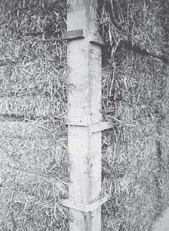
Bales held with horizontal 1-by-2s nailed to posts.
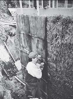
Forms placed with 1-by-2-inch spacers.
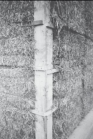
Walls after removal of forms.
The rest of the building was not built with this technique because of a tight schedule and because the site topography made scaffolding too labor intensive.
Comments and adjustments. The main purpose of Michel’s experiment was to find a way to raise an infilled modified post-and-beam structure in the shortest time possible with the smallest crew available. Even with the subsequent plastering necessary to cover the bare patches of bales, three people were able to raise and finish 464 square feet of wall in only three days. A conventional basement is usually prepared and poured in the same amount of time.
The speed of execution combined with the relatively small quantity of concrete required makes this approach more than appealing even for regular walls, providing the necessary equipment is available on-site. The pump is essential in this case, and we wouldn’t recommend doing without; hauling buckets of concrete to the top of the wall would be too burdensome.
To get a still more rigid wall by using the same idea, we would suggest sticking the form panels against the interior face of the bales and leaving a wider space on the outside, perhaps 2 or even 3 inches. For a very sturdy wall, horizontal rebar could be laid in the row joints and wire mesh attached to the exterior surface of the bales and spaced away with 1-by-2s or any other suitable device. That way the pouring could definitely be fast and most effective without the use of a vibrator (which is not recommended in vertical spaces), and without any risk of moving the bales out, because the forms will keep them stable on the other side. The resulting exterior reinforced skin would be uniform and ready for backfilling after waterproofing, which could be done in a conventional way. On a risky site a very safe waterproofing could be achieved with the use of a membrane.
The interior side of the walls (bare straw) can then be plastered by hand once the roof has been completed! Even with the extra cost of the pumping equipment, the total cost of this superinsulated basement (or even regular) wall would be incomparable to any conventional one. This alternative might also be the best choice for an exterior-pinned load-bearing wall. The ver-tical pinning stalks (bamboo, saplings, 1-by-2s, or even rebar) would hold the wire mesh away from the bale surface. This would bring the total cost even lower.
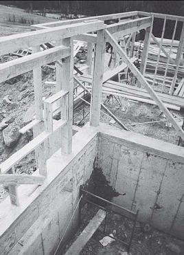
Structure built upon bale wall.
Concrete Slabs
The concrete slab has been the most popular foundation option for straw bale houses. This popularity derives from a pair of important qualities: A slab is a relatively inexpensive foundation that provides a very durable floor surface. The benefits of a slab floor extend beyond pure practicality, however. A well-finished slab can be a very beautiful floor surface. A concrete slab is also the ideal medium in which to lay radiant heating tubes. Until you have walked barefoot across a warm floor in midwinter, you cannot understand the therapy that this kind of heat provides to tired feet and ankles.
Slabs do have one drawback as cold-climate foundations, which is their tendency to hover close to the ground. This can be an issue on sites with seasonal high groundwater or in any design that does not include ample roof overhangs or gutters to keep the rain that hits the roof from splashing back against the walls. Most codes require that biodegradable materials be held 8 inches above finished grade. On questionable sites, we usually aim to keep the bales a minimum of 1 foot above finished grade; 11/2 or 2 feet is safer yet.
Conventional Slabs
Conventional concrete slabs fall into three cat-egories, according to the method employed to keep the slab from heaving. A slab with frost walls is the most common variety; in this case, foundation walls are poured to a frost-free depth, and the slab is poured inside these walls. The frost-protected shallow foundation works on the same principle, except that the frost-free depth is raised by a perimeter skirt of insulation. The “monolithic” or “Alaskan” slab accepts the possibility of the ground under the building moving slightly. Such a slab is built strong enough to float atop unsteady soil.
SLAB WITH FROST WALLS
A slab with frost walls is the conventional way of pouring a slab, and still the most common method. In cold-climate construction, this tech-nique involves excavating a trench to four or five feet below grade, and pouring a footing and foundation wall. The whole system is usually detailed as a basement wall would be, with footing drains and free-draining backfill. The main benefits of this system are that it is approved by code bodies everywhere, and that concrete contractors are quite familiar with it. This method involves enough excavation and concrete that the old argument for basements—dig down another four feet and create a usable space—often applies.
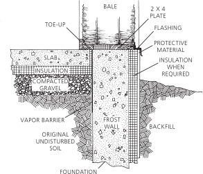
Typical frost wall with slab.
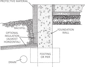
Typical frost-protected shallow foundation.
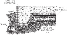
Typical monolithic slab. Some frost-protected shallow foundations also end up looking like this.
The slab is typically poured within the area demarcated by the foundation walls. Paul likes to use a thermal and expansion joint of 2-inch extruded polystyrene or mineral wool board between the edge of the slab and the foundation wall. See “Floor Slab Moisture Control,” later in this chapter, for other slab details.
FROST-PROTECTED SHALLOW FOUNDATION
The frost-protected shallow foundation is another kind of slab with frost walls. The only difference is that the frost walls need not extend nearly so deep, because the frost level is raised by insulation.
Design of these foundations is very specific to local climatic conditions. In some cases, insulation is run vertically down the foundation wall, and across the top and down the outside edge of the footing. In colder climates, a below-grade skirt of insulation extends two to six feet out from the foundation wall, in all directions. Design details are different for fully heated, semi-heated, and unheated spaces. See the bibliography for the National Association of Homebuilders’ design guidebook.
ALASKAN SLAB
In the case of an “Alaskan” or “monolithic” slab, the working assumption is that the ground below the slab will move, over time. Standard drainage precautions are still used, but the slab is built strong enough so that if the ground does move, the building can float, like a boat, to wherever it lands when the ground solidifies. This strategy was developed for Alaskan terrain above permafrost, which cannot be kept frost-free, and which suffers substantial movement during each spring thaw.
Floor Slab Moisture Control
Liquid water contact with basement floors is typically prevented by locating the foundation drain system at a level below that of the floor slab. Because any groundwater that rises to the elevation of the drain will be carried away from the building, this technique effectively drops the groundwater level to a point below the bottom of the slab. The site for the floor slab is next prepared by laying down a minimum of 4 inches of coarse gravel, as a capillary break, and also to help drain any water that rises under the bottom of the slab. This gravel layer should be con-tinuous with the gravel surrounding the foundation drain, so that groundwater has an unin-terrupted path away from the building. A layer of rigid insulation, 4 inches thick, is installed above the gravel, to keep the slab at a warm enough temperature so that it does not become a con-densing point for vapor held within interior air. This is a good place to spend some extra money up front—there is no such thing as retrofitting insulation under a slab.
Embodied
Energy in
Cement
Production
Basements and slabs use a lot of concrete, and concrete (or, more appropriately, the cement component of concrete) is a very energy-intensive material. According to the May/June 1993 edition of Environmental Building News (vol. 2, no. 3) a typical yard of concrete, delivered to a site, embodies 1,700,000 Btus of energy; 94 percent of this energy is consumed in the cement production process. To put this figure into context, EBN explains that U.S. cement production is roughly ten times as energy intensive as the U.S. economy as a whole. Cement accounts for roughly .06 percent of the U.S. economy, but is responsible for 0.6 percent of total U.S. energy use. (Of course, you can make a strong case that cement is also ten times more useful than most products of the U.S. economy, but that is another matter.) Carbon dioxide emissions from cement production, meanwhile, total 631 pounds per cubic yard of concrete. Carbon dioxide output is a more significant issue than energy use, in this case, as over 8 percent of all CO2 released into the atmosphere by human activities results from cement production.
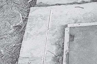
A thermal expansion joint of extruded polystyrene separates this concrete slab from the perimeter grade beam.
A layer of 6-mil polyethylene is sometimes installed above the insulation, as a vapor and radon barrier. An increasingly popular replacement for this practice is to tape the seams of the insulation board material.
In mixed heating/cooling climates, it is common to insulate only 4 feet at the perimeter of floor slabs. This technique is also sometimes used in cold climates, where it is a particularly bad idea. All through the year, the uninsulated portion of the floor will remain at a lower temperature than the air in the house. In winter, this results in cold feet and higher heating bills, while in summer (in humid climates) this cool area of the floor can cause water to condense out of the air, resulting in molds and an unhealthy indoor environment. Though it may save a few dollars during construction, poor detailing of this sort will increase heating bills and reduce comfort throughout the life of the building.
Toe-ups
Bale walls must be elevated off the surface of a slab, away from any water that might puddle on the floor during construction, and also as a protection against future plumbing leaks. An excellent toeup detail employs a combination of wood (for nailing) and rigid foam, rigid fiberglass, blocks of autoclaved aerated concrete, or RXL panels (for insulation). The 2-by-3s or 2-by-4s are nailed on the flat along the inside and outside planes of the bale wall. The gap between these two is filled by a strip of rigid insulation, which has the capacity to bear the weight of the bales above. At least one of the two wooden nailers (and typically the one that is on the air barrier side of the wall) is caulked or gasketed to the floor, as a defense against air leakage through the seam between it and the subfloor decking material. (This is crucial if the building is to receive wood siding, less so if exterior plaster is to be carried down over this seam.) If wood is not needed for nailing, the toeup can be made entirely of rigid insulation.
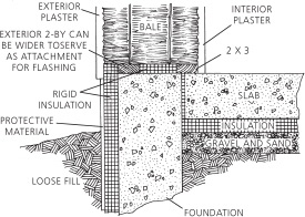
Typical toe-up.

Toe-up with blocks.
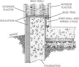
Toe-up with kneewall.
Some people replace the foam in the toeup with gravel. The problem with gravel is that it does not insulate, and the resulting cold surface at the base of the bales provides a potential point for condensation. If external foundation or rim joist insulation can be carried up to cover the outside of the toe-up, thereby keeping it warm, this system should work well.
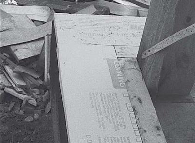
A wood and foam toeup over a slab or floor deck protects the bales from water that might pool on the floor during construction or a plumbing explosion.
Elevation of Bales
Contrary to common assumptions, a “slab on grade” need not be built at the original grade. In the case of a slab with frost walls or a shallow frost-protected foundation, the foundation walls can easily be extended one to two feet above grade. The area inside the foundation walls can then be backfilled, and the slab poured atop this fill. This is the simplest way to raise the level of the bale walls away from the ground. The only drawback is that it also raises the floor level, which is not always desirable.
Codes typically require some step-up between the finished grade and the floor of a house. In cases where a large step is not desirable, it is possible to elevate the bale wall on top of a built-up base of a nondegradable material.
Two courses of doubled-up concrete blocks, faced with 2 inches of rigid insulation, work quite well. This would yield a 16-inch-high, 18-inchwide wall. Faswall or Rastra blocks might also be of use here, as might gabions (stone-filled wire crates used for riverbank retention), rail-road ties, stone, sandbags filled with earth or soil-cement, or anything else you might dream up.
Alternately, you might bring an 8- or 10-inchwide foundation wall up to a height of one to two feet above the slab, and frame a wiring chase to the inside of it, atop the slab, to create the extra width necessary for full support of the bale wall. This detail accomplishes two jobs at once, elevating the bales while creating a large and convenient area for running cables of all sorts. Guy and Alice Snyder, of Snyder and Snyder Architects, Portland, Oregon, came up with a similar detail for a project in Washington County, Oregon. Their design does not include a wiring chase, but in-stead builds out the foundation wall with rigid insulation to the exterior and a framed and insulated kneewall to the interior. This detail could easily be modified to include a wiring chase.
Some bale builders, instead of elevating bale walls, have attempted to protect them by lapping asphalt felt or housewrap over the first course of bales, behind the exterior plaster. This is not a great idea. Though asphalt felt is somewhat vapor permeable (about as much so as cement stucco), it is quite impervious to liquid water. This is exactly the reason for employing it here, of course. The problem is that the felt blocks the movement of liquid water in either direction, so that if this bottom course of bales should ever become wet, a major drying mechanism— wicking into the plaster followed by evaporation into the air—will not be available. In order for liquid water to leave this bale, it must first change into a vapor state, so that it can pass through the felt layer. As always, the site must dictate the most sensible course of action.
The Archibio Sandwich Slab
Straw bale–insulated slabs have gained some popularity in recent years. Ecological and eco-nomic concerns have motivated a few pioneers to experiment with bales as insulation under concrete floors. Although not very well documented and not yet backed by scientific data, the observed performance of these slabs can make them attractive for very-cold-climate situations. With almost no other alternative to petroleum-based materials, bales represent an ideal low-cost so-lution to bring concrete slabs to the quality of comfortable floors.
Because the Archibio technique was described in The Straw Bale House (Chelsea Green, 1994), it became very popular. Reports from different sources revealed that casual misunderstandings of the technique had resulted in some very unfortunate experiments. The original procedure has been improved over the years, and Archibio hopes that a new, updated document will lead to a better understanding, not solely of the slab, but of the environment required for it to function adequately. We highly recommend that you check with Archibio for any more recent version of the plans for the sandwich slab.
SLAB DESCRIPTION
In climates where winters are long and demanding, nobody wants a cold and uncomfortable uninsulated concrete slab floor. While conventional insulation is usually provided by expensive petroleum-based rigid boards, no satisfactory natural material exists as an efficient and cheap alternative for those who want to live in a chemical-free environment. Because bales can be used in walls to create a high level of insulation, why not do the same with the floors?
ECONOMICS
The straw bale–insulated slab uses approximately 20 percent more concrete than a 6-inch-thick conventional slab for an equivalent floor area. But at a cost of between 50 cents and 1 dollar U.S. per square foot of R-50 straw insulation, no other insulated slab can ever be so affordable.
While the Archibio slab is like a big sandwich made of two concrete slices with a layer of bales in between, we know that some people in Mongolia, in order to save on concrete, labor, and cost, have experimented with straw-insulated slabs without a bottom layer of concrete. Similarly, to save even more, the top slab could be reduced to a thin layer of concrete and finished with an earthen floor (see “Earthen Floors,” in chapter 13).
SLAB PERFORMANCE AND
MOISTURE CONTROL
The key to good performance of the sandwich slab is to build it to be free of water and moisture damage. To clearly understand this issue, simply picture a straw bale wall tilted onto well-drained ground; if no moisture is present on the surface of the slab, it should behave like a wall. Some people would be tempted to lay a plastic sheet underneath the slab to prevent moisture migration from the ground; we don’t, for three main reasons. First, we create 100 percent water and damp-free conditions prior to slab pouring. Second, common sense and building science say that a vapor barrier should always be installed on the warm side of the building envelope. We think this rule should apply for floors or slabs as well, and in this case it would mean on top of the slab, which seems useless. Third, if water ever gets between the slab and the plastic, it could wick up through the concrete base slab and eventually damage the straw. It would actually be more advisable to lay the plas-tic underneath the drainage layer of gravel.
As explained in chapter 2, moisture may enter slabs by three processes: bulk leakage, capillary action through pores in the concrete, and vapor migration. Bulk leakage and capillary wicking are prevented by back-filling and draining in such a way that it is impossible for liquid water to remain in contact with the slab. Vapor can move out of the soil and into the slab at a very slow rate because concrete has a low perm rating. Because we suggest finishing the floor with materials that are at least as vaporpermeable as the slab (natural sealers and wax rather than epoxy sealers and the like), vapor should migrate the same way through the top slab and thus not present a problem. In addition, the slab is at the same temperature or warmer than the soil, and the vapor is coming out of the soil. No cold spot, no condensation. Similarly, vapor from interior air will not condense on the slab, because the slab is insulated, so its surface should be warm. With a radiant heating system in the slab, the possibility for con-densation is further reduced.
Moisture may enter slabs by bulk leakage, capillary action through pores in the concrete, and vapor migration.
IMPORTANT WARNING
Since our first experience, in 1984, Archibio has supervised the construction of more than fifty slabs with a total of 60,000 square feet of floor area. Although no visible moisture problem had ever been reported for any of the slabs, Archibio had the opportunity to test for potential moisture effects in four slabs in November 1999 under the close supervision of Canada Mortgage and Housing Corporation’s (CMHC) experts. In brief, it was found that water infiltration inside the sandwich occurred almost inevita-bly on risky sites, with some degree of bale deterioration as a result. In the worst case the straw was almost completely composted. In a few other cases, just a small amount of straw had deteriorated by direct contact with water, while the remaining straw was sound although with a high moisture content. In the best case, the bottom half-inch layer was decomposing while the rest was sound throughout but with a higher than normal moisture content. Sensors were installed in the tested slabs and in a recently built one, so more data should be available in the future to evaluate long-term performance.
A fuller discussion of these tests is reported in chapter 14 of this book. The complete detailed results of the tests are available directly from CMHC or Archibio. We strongly recommend that you consult these documents and/or contact Archibio before building your own slab.
PHYSICAL COMPONENTS
The basic sandwich slab is made of full bales laid flat, side-by-side, on a 2-inch layer of concrete; the rounded butt corners where bales meet are filled with poured concrete pillars. Spaced according to the size of the bales, the pillars form a grid of 18 inches on one axis and of bale lengths (usually about 3 feet) on the opposite axis. These are intended to carry the weight from the top slab down to the base slab on the ground. Because we don’t want to create a Faraday grid effect by reinforcing with wire mesh, we add chopped straw in the concrete mix before doing these two pours. (The “Faraday effect” is a change in electromagnetic field caused by conductive materials used in certain grid configurations. Some experts consider it to be unhealthy to humans.) A 3-inch-thick top slab is then poured on the bale surface, with or without chopped straw in it depending on its desired final texture.
This design is based on the low-cost plunger pile slab developed by Dr. Billig of the Central Building Research Institute of India and described in Ken Kern’s The Owner-Built Home. Dr. Billig’s light-duty floor, which was subjected to loading stresses of up to 450 pounds per square foot without showing any sign of distress, was a 1-inch-thick concrete layer poured on a piece of fabric laid across piles that were spaced on 3-foot centers. These had previously been poured in predrilled holes in a lightly rototilled soil. The later settling of the soil made the floor rest only on the piles, separated from the ground by a very shallow crawlspace.
Because our top slab is at least three times thicker and rests on a tighter grid of piles, we believe that any bale settling after the final setting of the concrete would be of no significant consequence to the system’s structural performance. In the worst case, bales collapsing inside the sandwiched slab would create a small airtight crawlspace without reducing the structural integrity of the floor slab. The tests conducted in the autumn of 1999 confirmed that rotten collapsing bales do not affect the structural capacity of the slab system.
SITE PREPARATION
As previously mentioned, because we want our slab built in the best possible conditions, our first concern is site drainage. We start by installing perimeter drains below the bottom slab level. On sloping sites we suggest building reversed vshaped diverting berms on the upper side of the slope, behind the building, to drain water away on the sides.
We always make sure there is no underground source of water or rising dampness under the slab. When such risks exist, such as on soils with high contents of clay that could wick water from any nearby source, we suggest removing as much of that soil as possible under the projected base slab. (In one particular project, we removed as much as 4 feet of soil.) The hole is then filled with pure sand or gravel, compacted mechanically, and topped with at least 6 inches of coarse gravel to block capillary action and to ensure superior drainage.
When there is no risk of water infiltration, the topsoil and subsoil are removed to 6 inches under the depth of the desired base slab level (ap-proximately 14 inches below the exterior finished grade so that the finished slab level will be at 6 inches above grade), and that 6 inches is filled with compacted gravel before pouring.
SLAB COMPOSITION
We use a 3,000 psi concrete mix for all our pours except when a stronger bearing capacity is needed, whereas then we use a 4,000 psi mix. For best workability we use half-inch net aggregates that fill thin surfaces and small gaps effectively. Low-slump mixes are also easier to work with, for the base and top slabs. Unless conditions are unpredictable, we always try to avoid using chemical additives in the mixes.
POURING THE SLAB
At the arrival of the truck mixer on-site, we add chopped straw in the amount of one-third of a bale for every cubic yard of the concrete mix. It is then left spinning for a few minutes. (Because mixer drivers are unfamiliar with this idea and sometimes quite skeptical about it, this procedure should definitely be checked beforehand with the dispatcher when the load is ordered.)
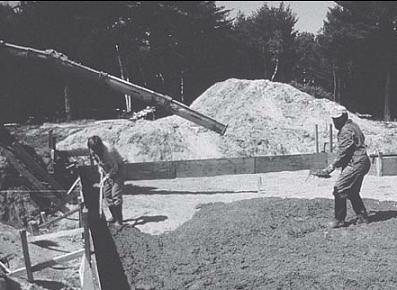
Pouring the base slab.
The idea, of course, is to use the truck to thoroughly mix the straw into the concrete. The straw has to be previously chopped into loose fibers no more than 4 inches long. A good and quick way to chop the straw is by making two chain-saw cuts along the strings through the bale. When large amounts of fibers are needed, we shred loose straw in a garden mulcher. The straw is added by small handfuls, in order to allow it to mix well. Because overtime is always charged, it’s better to have the chopped straw ready and handy in bags or buckets before the truck arrives.
Because the added straw eats up a bit of water, the driver has to add water as the mix thickens. Make him add just enough to be able to pour, otherwise the water weakens the concrete.
When the mix is ready, we pour the straw-reinforced concrete on the gravel base; 2 inches is usually enough to uniformly cover the entire surface. At this stage two options are possible depending on the size of the project and the number of helpers available. For small projects, the concrete is left to set for a few hours before bales are laid on it to cover the entire surface, we then proceed with the next step. For large projects with frost walls to bear the framed baled walls, in which the roof has to be finished before any sort of bale work is started, the base slab is left uncovered until the roof is up.
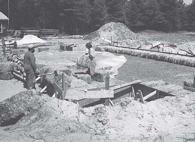
Bales laid on the base slab.
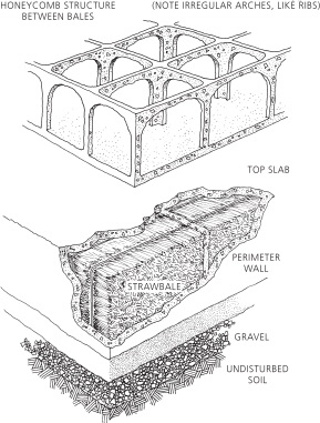
Honeycomb structure of straw bale slab.
It is worth mentioning here that the frost walls built to support the framed walls need to be insulated to at least the same depth as the straw bale slab in order to prevent the concrete from freezing and becoming a potential thermal bridge and a good spot for condensation. We usually apply Roxul rigid panels on the exterior side of the concrete wall and finish them with netting and plaster. A 10-inch-thick wall with 4 inches of insulation will allow for alignment with the plaster applied on the bales and thus make a vertical continuity in the plaster finish.
In cases where capillarity is a concern it is possible to create a capillary break by making a horizontal saw cut across the plaster, after it has set well, a few inches below the top of the rigid in-sulation. The kerf can then be sealed with regular caulking material. This stops any rising moisture from getting to the bales at the base of the wall. This method is also much easier than try-ing to insert regular continuous flashing at the base of the curvy irregular surface of the plastered bale wall.
PLACING BALES
The bales are laid by placing them side-by-side, barely touching each other, making sure there is a vertical gap left at the corners to pour the piles. When the void seems insufficient, the corners may be beveled with a chain-saw cut or the gap simply widened with a stick. Bales that would be inappropriate for walls because of inadequate length may be used for this application. At spots where supports are needed for chimneys, posts, and other structural elements, pads are poured and sufficient space is left open to place these elements between the bales.
POURING PILES
This next operation requires very special care.
Chopped straw is once again combined with the concrete in the mixer. This time approximately 25 percent more concrete is needed than for the base slab. Once well mixed, the straw-reinforced concrete is either dumped, carried along, or pumped on top of the bales, and tossed carefully into the corner cavities with thick sticks such as 2-by-3s, making sure they are completely filled from bottom to top, thus forming strong piles to carry the weight of the top slab. Because of the uneven shapes of the bales there are usually lateral gaps between the piles. These gaps are filled loosely from the top, with the intention of forming small arches spanning from pile to pile like a honeycomb structure.
Because this operation is time consuming, it is best carried out by a large crew of people. The piles are the structural key of the sandwich slab, so it is critical that they be poured with care.
To prevent damaging the bales from the volume of traffic on them, we suggest laying plywood sheets or wooden boards as walkways.
The pour is stopped after the top of the bales are covered by a fine layer of concrete. The work is then left to firmly set overnight or longer, according to conditions.
These first two operations can be done on the same day or on two separate days, depending on the size of the floor. At this stage, some plumbing equipment, such as sewage pipes or electrical conduits, may have to be installed before any further pouring is done. Usually, we have previously notched the bales with chain-saw runs to create the channels needed for these purposes. We make these on the top part of the bales, just below the interior top slab level, so that they still have some insulation left underneath while being easy to reach for maintenance, if ever necessary. Then, if the floor has been planned with a radiant heating system, the tubes are installed on top of the slightly covered bales before the last pour is done.
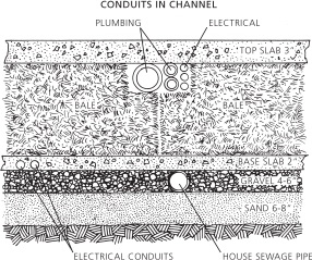
Ditch or channel cut into bales for pipes and conduits.
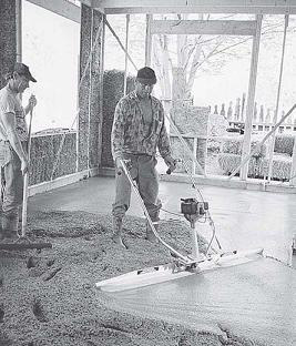
Mechanical floating of the top slab.
The final step is to pour the top slab. We use a 4,000 psi, low-slump concrete mix with finer aggregates when the concrete floor is to be left exposed. Depending on the desired finish, this pour may or may not contain chopped straw (see “Floor Finishes,” in chapter 13). There are various curing methods, but the easiest one is to cover the entire surface with a plastic sheet immediately after the floating has been completed, and to keep it protected for a minimum of seven days, and ideally as many as twenty-eight days. This step is critical for an exposed slab.
When the slab is not going to be left exposed and has no heating tubes, this final pour of concrete may be approximately 2 inches thick and simply bull floated. (A bull float is a 4-foot-wide steel trowel with a very long broomstick-type handle, used for the initial surfacing of a concrete slab.) Otherwise, a total of 3 inches with the tubes are a minimum for the slab to perform adequately as a heating system.
Other Types of Foundations
Depending on the size of the project, the conditions of the site, and the building resources avail-able, some other less conventional foundation options may be worth an evaluation. Because all of the following systems have proved their reliability, there is no reason why they couldn’t work with bale walls, properly detailed.
Piers
Poured concrete piers use very little material and can easily be owner-built; they are, therefore, among the least expensive foundation options. Piers also accommodate uneven terrain and high water tables. As the holes are typically dug by a small backhoe or by hand, site disturbance is minimal. Piers are an excellent foundation option for sites that are difficult to access by machine, because they can be poured with concrete mixed on site, either in a portable mixer, or by hand in a wheelbarrow. Piers need not neces-sarily be made of concrete; rot-resistant wood species, pressure-treated poles, or salvaged telephone poles can also work well.
On the negative side, a house on piers tends to look rickety and disconnected from its site. This effect is exacerbated in the case of a plastered bale building; a structure with such a massive feel really wants to be anchored to the ground. Thermally, a cold-climate building is better off having one of its sides in contact with 50°F (10°C) earth than with cold winter air. The ecological tradeoff, here, is that the floor of a building on piers can be insulated with blown cellulose, rockwool batts, or even bales, rather than rigid foam.
Piers typically support carrying beams, which, in turn, support a framed floor system of joists and decking, upon which your bales will rest, high and dry. Whenever possible, Paul likes to cantilever beams 1 to 2 feet beyond perimeter piers, and likewise cantilever floor joists a similar distance beyond perimeter beams. The idea here is to recess the piers, so that you don’t have to look at them. (Horizontal shear can be an issue in this situation. Be sure to take this into account in your load calculations.) You might also choose to dry-lay stone outside the piers, at the building’s perimeter; this strategy combines the beauty of stone with the strength of concrete, re-moving the need to pay careful attention to the structural integrity of your dry-laid stone wall.
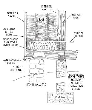
Pier foundation.
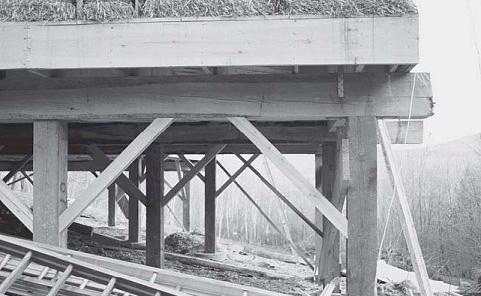
Wooden piers accommodate a severely sloping site. Chapin home, Phillips, Maine.
If the bales in your building are to be wrapped around an internal post-and-beam system, then the cantilever of your floor deck should be sized such that the structural columns within the living area are placed directly over the piers—the structural columns that will carry the weight of your building down to solid soil.
The floor of a building on piers should be detailed as if it were an outside wall. This can be tricky, because the plane at the bottom of the joists is regularly interrupted by carrying beams. It’s not a bad idea, if this plane is to become your air barrier layer, to lap a strip of plastic or housewrap over the beams, before setting the joists. This can then be caulked to whatever sheet material you apply to the underside of the joists. Even if your air barrier is to the interior, you will want to cover the underside of the joists, to prevent massive wind-washing through the floor insulation. In combination with blown cellulose insulation, GreenSpace has had good luck with 1/2-inch homasote (commercially produced pressed-paper board, suggested by Tony Walker of Cellu-Spray insulation, Shelburne Falls, Massachusetts—the mis-sionary of cellulose). A combination of housewrap and hardware cloth (to deter rodents) also works, as does plywood, or boards.
Experience tells us that the greatest problem faced by buildings on piers is not structural—it is frozen pipes. Horizontal plumbing lines must be run either in the upper third of the joist zone, or in interior walls. It is a fact of physics, however, that if you have running water in a house, then the water needs to both enter and leave. Unfortunately, in a house built on piers, this means that the main supply and waste lines must pass through the open air, as they make their way between the building and the ground. Waste lines are not a major issue, as the water in them is usually moving along at a pretty good clip. In a supply line, however, water will often sit overnight, and occasionally for days or weeks, without mov-ing; this means that the pipe will freeze solid, and burst.
The safest way to avoid the prospect of frozen pipes is to accept the need for a small crawlspace or cellar under a portion of the building. This space can be as small as 4 feet by 4 feet. It should have insulated walls, and should extend below the frost line. Aside from protecting the plumbing lines, larger versions of this space can house wine and potatoes, or double as a mechanical room. The boiler or furnace, in this case, would provide waste heat, as added insurance against frozen pipes.
Special attention must also be paid to traps under tubs and showers; these can often end up far enough down in the joist zone that they will be separated by insulation from the heat of the building. You might need to bump down an insulated area below such traps. By all means, avoid insulating above them. And don’t expect plumbing or insulation contractors to be thinking about such things; they have lots of other problems to worry about. The responsibility is on the designer to ensure that such important details end up on the house plans.
Moisture should not be much of an issue under a building on piers, as the space below is typically in continuous conversation with the out-side air. In situations where this is not the case— when the building is close to the ground, for in-stance, or when the space between the ground and the building is carefully filled with stones— and where the ground under the building is wet for long portions of the year, it can be a good idea to lay a sheet of polyethylene over the soil, to block moisture from moving up and challenging the integrity of the building’s components. Also be aware that by closing in the area under a house on piers, you are creating a very nice home for the local rodent population.
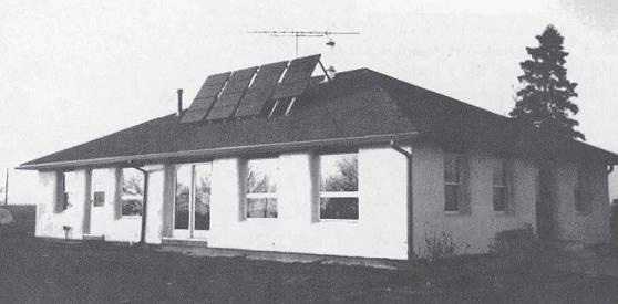
A pole-framed building can sit comfortably close to the ground. The completed Haeme home, Kempton, Illinois.
Pole Framing
Pole framing is similar to building on piers, in that columns bear all loads down to a frost-free soil depth. Whereas piers end at the floor carrying beam, however, poles typically run all the way up through the wall, to the roof framing system.
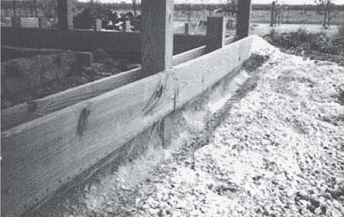
Pole framing: Buried poles run all the way to the roof, and bolted-on beams support floor joists. Haeme home, Kempton, Illinois.
Floor framing is hung from the poles, so the floor can be set at any height that seems appro-priate, given local weather patterns and land forms. This system, therefore, offers the option of raising the bales a significant distance above the ground.
The second benefit of pole construction to bale builders is that in one-story construction, the fact that the poles are buried 4 to 5 feet in the earth provides all of the necessary lateral bracing to the wall. This means no diagonal braces to in-terfere with bale laying or window placement.
Poles are typically of rot-resistant or treated wood, though they can also be made of poured concrete. Such a system could mesh quite nicely with the depth of the bale wall.
Rubble Trench and Grade Beam
The grade beam is like a floating slab, without the slab. It might be called a floating beam, though it is specifically designed never to touch water; it is a beam of concrete poured on top of a rubble-filled trench. Water drains down through the rubble, and the beam is left high and dry, immune to heaving, floating on a piling of air.
A grade beam allows for flexibility in your choice of floor material. The floor might be stone, or brick, or the increasingly popular poured adobe. It might be concrete, poured in small panels. Because concrete sets up more evenly when it is not exposed to direct sunlight and heat, it is not a bad idea to pour your floor after putting on your roof, even if you intend to pour in a con-tinuous slab. A slab poured late in the construction process will not suffer the chips from dropped hammers that inevitably plague the monolithic slab.
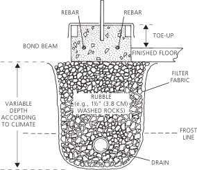
Rubble-trench footing.
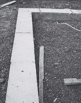
This grade beam sits on a 4-foot-deep trench filled with rubble and drained by perforated pipe, so it should be safe from frost heaving even in frigid New York State.
It is quite possible to use a foam-form product, or Rastra or Faswall, to create a 2-or 3-foot-high grade beam/wall, sitting atop a rubble trench. Such a hybrid beam would elevate the bales nicely, with minimal use of concrete.
Stone and Earthbags
No rule says that the beam above your rubble trench needs to be made of concrete. The mono-lithic nature of reinforced concrete adds strength to the structure, of course, but those willing to experiment can certainly come up with other material options. Stone, either dry-laid, mortared, or slip-formed with concrete can be an excellent choice for sites where lots of it is lying around.
Some builders have also had success using sandbags as forms for tamped-in-place soil-cement blocks. This technique, known as earthbag construction, was first developed by Nader Kha-lili and others at CalEarth, in Hesperia, California, where entire structures—walls and vaulted roofs—are being built by this method.
The soil mix is typically filled into bags, which are then set in place in the wall, and tamped to create a solid mass. Barbed wire is often run between courses of bags, to keep them from slid-ing, and rocks are also sometimes placed to form a key. Alternately, a groove can be pounded into the center of each bag, parallel to the direction of the wall, so that each course of bags can nest down into the course below.
If the soil on your site is between 15 and 20 percent clay, it can work with little or no cement stabilization. Lower percentages of clay require that cement be added, as a binder. Proportions are typical of rammed earth construction; a 10 percent clay mix would want 5 to 10 percent cement, while a soil with no clay content would want 10 to 20 percent cement. If the soil is damp, sufficient moisture should be available to set the cement; in dry conditions, the wall can be soaked after it is built, to help the cement to set. The main drawback to this method is that the tamping requires quite a lot of rather brute labor. While it is possible that Paul was somewhat more compulsive than necessary in his bag tamping, he feels compelled to warn anyone considering this method to avoid its use at times of the year when spinach is not available in abundant quantities. Regardless of how burly you may consider yourself to be, pounding these bags will leave you quite sore by the end of the day!
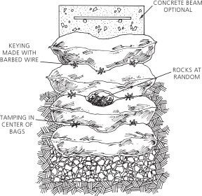
Three ways of keying courses in earthbag foundations.
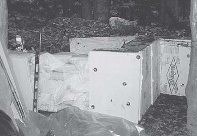
An earthbag wall, partially covered by foam insulation.
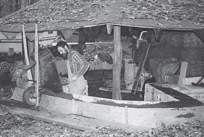
Paul pours a concrete bond beam atop an earthbag wall, to create a level surface for framing. Note separate foundation for poles supporting the roof.The earthbags will support only the bales and windows.
An alternate approach is to assume that the bag will last indefinitely as a structural component of the wall. In this case, the fill material need not be compressed or stabilized into a cohesive block. Gravel-filled bags have sometimes been used as a foundation material under bale build-ings; the gravel serves the secondary purpose of forming a capillary break between the bales and the ground. The trick with this approach is to find a bag that will not begin to photodegrade during the construction process. Because sandbags are typically made for temporary installa-tions, they are generally not designed for durability. Depending on your local supply of bags, you may find it necessary to plaster the foundation immediately after stacking it. It can also be quite difficult to acquire strength ratings from the manufacturers.
Earthbag or stone walls can work particularly well in a hybrid foundation system, where either poles, or posts on piers, bear the roof load down to the frost line, while stones or sandbags, atop a rubble trench, support the bale walls.
It should be clear that no one foundation system is most suitable to bale construction. Most foun-dations will work fine; once the need to support the wide walls is covered, other aspects of the design, including the site conditions, are really more important than the bales.
1 . K. N. Burn, “Action du Gel sur les Fondations,” Digest de la Construction au Canada (Conseil National de Recherches Canada, Division des recherches sur le Bâtiment, CBD 182F, April 1977).
2 . Stuart Brand, How Buildings Learn (New York: Viking Penguin, 1994).