Chapter 10. Sensors, Sensors, Sensors
When you’re building a robot, some of its most important parts are its sensors. If the computer (the Pi, in our case) is the rover’s brain, then the sensors you choose to pack into it are its eyes (a camera), ears (ultrasound), touch (reed switches and thermometers), equilibrium (accelerometers), and even senses that humans don’t have, like magnetic field detection. The goal of most robots is not just to have sensors to receive input from the outside world, but to act on that input and do something. In the preceding chapter, we learned how to remember where our rover has been, and we touched on the possibility of autonomously navigating to those locations. But just navigating to them is kind of boring unless you can then use sensors to gather information from those points.
There are a lot of sensor possibilities you can use on your rover; I went over a few of them in Chapter 4, and if you spend a bit of time browsing some of the popular electronic sites such as Adafruit or Sparkfun with a credit card and no spending limit, it’s pretty much a sure bet that before long you’ll have more sensors than you know what to do with. There are accelerometers and magnetometers and Hall effect sensors and reed switches and ultrasonic range finders and laser range finders, and the list goes on and on. In fact, you may be limited only by the size of your rover’s body and by the number of GPIO pins available to you. (If you do find yourself running out of room, you may want to consider trying the Gertboard to expand your I/O potential.) In the meantime, two medium-sized breadboards should be plenty, depending on how well they fit in your rover’s chassis.
In this chapter, I wanted to introduce some of the most common sensors and walk you through the process of setting them up and reading from them. Some sensors are quite basic—all you have to do is plug in electrical power and one or two signal wires, and you read the results. Others require libraries from third parties, like the SH15 temperature sensors. And some of them use the I2C protocol, a common way of communicating with external devices (sensors and other things) that are connected to the Pi. (For more on the I2C protocol, look to the end of this chapter.)
Most of these sensors will come as fully assembled PCBs, but with the option of adding a row of soldered headers. I fully encourage you to solder the headers onto the board. It makes connecting and disconnecting each sensor via a breadboard a snap, and allows you to add to and subtract from your project easily. If you have more sensors than you can comfortably connect, having them all breadboarded will allow you to swap them out as needed.
If you’re still new to soldering, fear not: soldering headers to a board is a good way to get used to the process, as the solder-phobic coating on the boards makes it pretty easy to keep the solder where it’s supposed to be. Just remember: heat the joint, not the solder, and you should be fine.
SHT15 Temperature Sensor
The Sensirion SHT15 is kind of a pricey sensor, retailing at about $30–$35, but it’s also easy to install and use, which is why I recommend it. It doesn’t use the I2C protocol (though it has pins labeled DATA and CLK, so it looks like it does); rather, you just plug the wires into your Pi, install the necessary library, and read the values it sends.
To use it, you’ll first need to connect it. For our example, connect the Vcc pin to the Pi’s 5V pin, and the GND pin to the Pi’s GND. Then connect the CLK pin to pin 7, and the DATA pin to pin 11. You’ll also need to install the rpiSht1x Python library by Luca Nobili. This is not a system-wide library, so navigate to within the directory where you’ll be writing all of your rover code and download the library with
wget http://bit.ly/1i4z4Lh
When it’s finished downloading, rename the file from the bit.ly name to what it should be with
mv 1i4z4Lh rpiSht1x-1.2.tar.gz
and then expand the result with
tar -xvzf rpiSht1x-1.2.tar.gz
Navigate into the resulting directory and install the library with
sudo python setup.py install
That should make the library accessible to you, so move up one level (back to your rover directory) and try the following script:
fromsht1x.Sht1ximportSht1xasSHT1xdataPin=11clkPin=7sht1x=SHT1x(dataPin,clkPin,SHT1x.GPIO_BOARD)temperature=sht1x.read_temperature_C()humidity=sht1x.read_humidity()dewPoint=sht1x.calculate_dew_point(temperature,humidity)("Temperature: {} Humidity: {} Dew Point: {}".format(temperature,humidity,dewPoint))
Save this with the filename readsht15.py, and run it with sudo:
sudo python readsht15.py
You should be greeted by a line of text describing your current conditions, something like
Temperature: 72.824 Humidity: 24.2825
Dew Point: 1.221063
This is the function you can use in your final rover code to access current temperature and humidity conditions.
Ultrasonic Sensor
The HC-SR04 ultrasonic range finder on the rover uses ultrasound to determine the distance between it and a reflective surface such as a wall, a tree, or a person. The sensor sends an ultrasonic pulse, listens for the echo, and then measures how long it took to receive that echo. The HC-SR04 is easy to configure on the Pi, and needs only two GPIO pins in order to work: one output pin and one input pin. The one caveat is that you should place a 1K resistor between the sensor and the Pi’s input pin, as the HC-SR04 outputs 5V. This might damage the Pi’s pin, as the Pi expects 3.3V as inputs, so a resistor brings the incoming voltage down to a Pi-safe level.
To power the HC-SR04, connect the sensor’s Vcc and GND pins to the Pi’s 5V and GND pins, respectively. Then choose two GPIO pins to be the trigger and echo pins. The trigger pin will be an output, and the echo pin will be an input. According to its datasheet, a quick ON pulse of 10 microseconds to the trigger pin will trigger the sensor to send eight ultrasonic 40KHz cycles and listen for the return on the echo pin. Luckily for us, Python’s time library can be used to send microsecond-long pulses.
For the purposes of experimentation, let’s hook up the sensor to pin 15 as the trigger and pin 13 as the echo. You can then use the following code to test the range finder:
importtimeimportRPi.GPIOasGPIOGPIO.setmode(GPIO.BCM)GPIO.setup(23,GPIO.OUT)GPIO.setup(24,GPIO.IN)defread_distance():GPIO.output(23,True)time.sleep(0.005)GPIO.output(23,False)whileGPIO.input(24)==0:signaloff=time.time()whileGPIO.input(24)==1:signalon=time.time()timepassed=signalon-signaloffdistance=timepassed*17000returndistancewhileTrue:'Distance:%fcm'%read_distance()
After importing the necessary libraries, we set up the GPIO pins to read and
write. Then, in the read_distance() function, we send a 10-microsecond pulse
to the sensor to activate the ultrasonic cycles.
After the pulse is sent, we listen for the echo on pin 27 until we get a 1
(meaning an echo has been sensed). We then mark how long it’s been since the
pulse was sent, multiply that by 17,000 (as directed by the README file) to
convert it to centimeters, print it, and repeat with a while loop.
When you save and run this script (as sudo, remember, because you’re accessing
the GPIO pins), you should be able to wave your hand in front of the sensor and
watch the values change with the distance to your hand. Keep this code handy,
as the read_distance function will be used in our final code.
Photoresistor
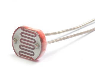
A useful sensor to have in various situations, a photoresistor is a resistor whose resistance changes depending on the amount of ambient light (Figure 10-1).
The photoresistor exhibits photoconductivity; in other words, the resistance decreases as the amount of incident light increases. Many of these resistors have a phenomenally wide range: nearly no resistance in full-light conditions, and up to several megaohms of resistance in near-dark. Photoresistors can tell you that your rover is working at night, for instance, or that it’s in a tunnel, or that it’s been eaten by a velociraptor.
The one caveat to using a photoresistor, however, is that you can’t just plug it into your Pi and expect to read values from it. The photoresistor outputs analog values, and the Pi understands only digital ones. Thus, in order to convert its values into something the Pi can understand, you must hook it up to an analog-to-digital converter, or ADC chip.
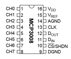
The chip I use is the MCP3008, an eight-channel 10-bit converter IC available from several online retailers for around $5. Yes, you can easily get a more precise chip, with a 12- or a 16-bit converter, but unless you’re measuring something that requires extreme precision, I don’t think it’s necessary. All we need are ambient light levels, and 10-bit precision seems to be plenty. It has 16 pins; pins 1–8 (on the left side) are the inputs, and pins 9–16 are voltage, ground, and data pins (Figure 10-2).
To read from the photoresistor, we’ll use only one of the MCP3008’s inputs, leaving seven inputs free for other analog devices we might wish to add later. The chip uses the SPI bus protocol, which is supported by the GPIO pins.
To use the chip and the photoresistor, you’ll need to start by enabling the SPI hardware interface on the Pi. You may need to edit your blacklist file, if you have one. The blacklist.conf file is used by the Pi to prevent it from loading unnecessary and unused modules, and it exists only in earlier versions of Raspbian. Later versions don’t have any modules blocked. See if /etc/modprobe.d/raspi-blacklist.conf exists on your Pi; if it does, comment out the line
spi-bcm2708
and reboot. After rebooting, if you type lsmod, you should see spi_bcm2708
included in the output—most likely toward the end.
You’ll then need to install the Python SPI wrapper, with a library called
py-spidev. First make sure you have the python-dev package:
sudo apt-get install python-dev
Then navigate to your rover’s main directory, and download and install py-spidev with
wget https://raw.github.com/doceme/
py-spidev/master/setup.py
wget https://raw.github.com/doceme/
py-spidev/master/spidev_module.c
sudo python setup.py install
The library should be ready for use.
Now you can connect the chip to the Pi. Pins 9 and 14 on the MCP3008 should be connected to GND on the Pi; pins 15 and 16 should be connected to the Pi’s 3.3V (you’ll need to use one of the power rails on your breadboard). Then connect pin 13 to GPIO 11 on the Pi, pin 12 to GPIO 9, pin 11 to GPIO 10, and pin 10 to GPIO 8. Finally, for testing purposes, connect one leg of the photoresistor to pin 1, and connect the other leg to the ground rail.
When it’s connected, all you need to do is open an SPI bus with a Python script and read the values from the resistor. The script should be something like this:
importtimeimportspidevspi=spidev.Spidev()spiopen(0,0)defreadChannel(channel):adc=spi.xfer2([1,(8+channel)<<4,0])data=((adc[1]&3)<<8)+adc[2]returndatawhileTrue:lightLevel=readChannel(0)"Light level: "+str(readChannel(0))time.sleep(1)
Running this script (as sudo, because you’re accessing the GPIO pins) should result in a running list of the values of the light hitting the resistor. The readChannel() function sends three bytes (00000001, 10000000, and 00000000) to the chip, which then responds with three different bytes. The data is extracted from the response and returned. You can test the system by waving your hand in front of the resistor to block out some light. If the resistance value changes, you know that everything is working properly. As with the other scripts, keep this one in your main rover folder for use in your final program.
Magnetic Sensor
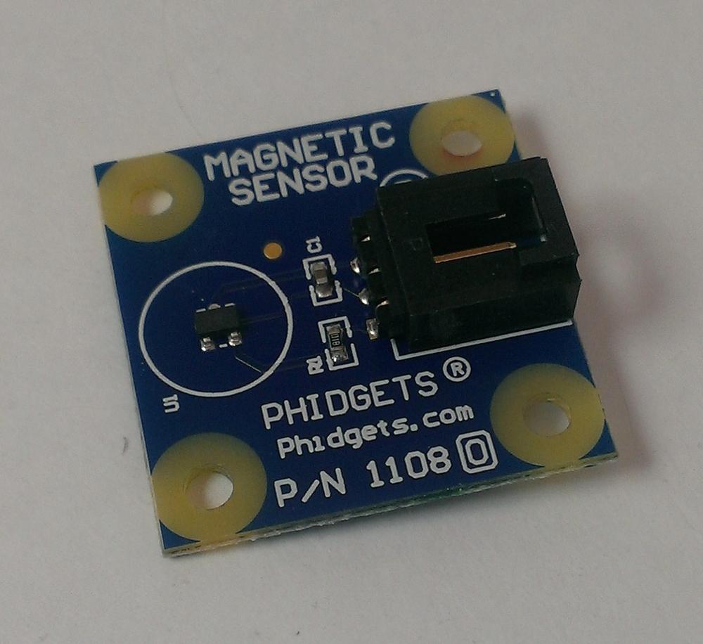
The magnetic sensor, or Hall effect sensor, is a nifty little device that doesn’t have a whole lot of uses outside of a certain small niche of applications. While I’m not certain it may be used on the rover, you may find yourself wanting to know if you’re parked in the middle of a strong magnetic field (Figure 10-3).
At its core, the Hall effect sensor is nothing more than a simple switch, so no real programming is required, nor are there any special libraries. To test it, connect the red (Vcc) pin to pin 2 on the Pi, connect the black pin to the Pi’s GND pin (6), and connect the white signal wire to pin 11. Now just try the following code:
importtimeimportRPi.GPIOasGPIOGPIO.setwarnings(false)GPIO.setmode(GPIO.BOARD)GPIO.setup(11,GPIO.IN,pull_up_down=GPIO.PUD_DOWN)prev_input=0whileTrue:input=GPIO.input(11)if((notprev_input)andinput):"Field changed."prev_input=inputtime.sleep(0.05)
This script continually polls pin 11 to see if the input has changed (between
prev_input to input). When you run it, your terminal should remain blank
until you wave a magnet near the sensor. (You might have to experiment with
different proximities and speeds; my experience is that the magnet has to come
within a few inches of the sensor to register as a “pass”). Once you have it working,
you can mount the magnet wherever you’d like to sense it, and poll the Hall effect
sensor. When the magnetic field has changed, you know your robot is next to a
magnet.
Reed Switch
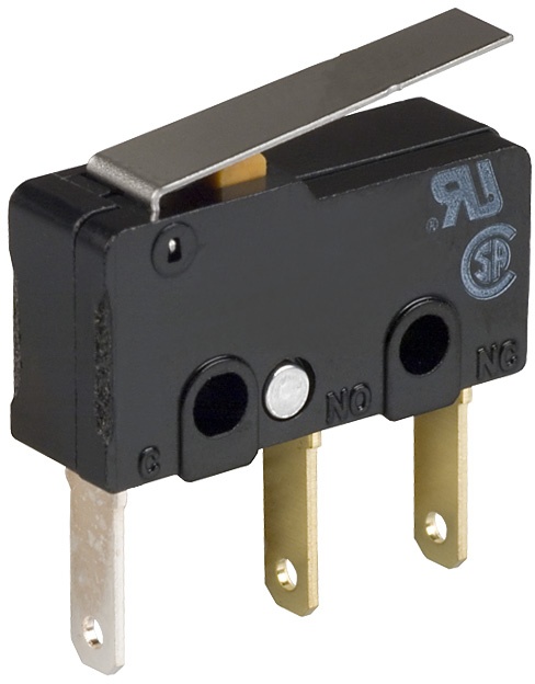
Probably the easiest switch to program and connect is the reed switch, also called a snap-action switch (Figure 10-4).
The reed switch is often used by robots to determine the limits of some form of motion, from obstacle avoidance to grip control. It’s a simple concept: the switch is normally open, permitting no current to pass. When an object presses on the switch, current is allowed through and the connected GPIO pin registers an INPUT.
Because you’re using a physical switch, it’s important that you’re familiar with the concept of debouncing. Switches are often made of springy metal, and that can cause them to quickly “bounce” apart one or more times when they’re first activated, before they finally close. An old analog circuit wouldn’t register that “chatter,” but a processor such as the Pi has no problem registering them. In the microseconds after contact is made, the Pi might be reading something like ON, OFF, OFF, ON, ON, OFF, ON, OFF, ON, OFF, ON, ON, OFF, ON, ON, OFF, ON, before settling down to a steady ON state. You and I know that the switch was triggered only once, but to the Pi, there was a festival of multiple switch triggers. This can cause problems when the program is running: did the robot run into an obstacle once, or dozens of times? The solution lies in software. By telling the Pi to wait until the chatter has quieted before reading a value, we debounce the switch.
Early versions of the GPIO library made you do this yourself, in code, but later versions give it to you as a built-in capability. To demonstrate, I’ll also show you the concept of an interrupt, where the Pi will stop whatever it’s doing and alert you when something interesting happens at a pin.
Start by connecting the switch to your Pi. Wire one side of it to pin 11 (GPIO 17) and the other to the Pi’s GND pin. If we pull the pin HIGH with a virtual pull-up resistor, then the input pin will register a switch close as being connected to ground. All that’s left is to write some code to read it:
importtimeimportRPi.GPIOasGPIOGPIO.setmode(GPIO.BOARD)GPIO.setup(11,GPIO.IN,pull_up_down=GPIO.PUD_UP)defswitch_closed(channel):"Switch closed"# This next line is the interruptGPIO.add_event_detect(11,GPIO.FALLING,callback=switch_closed,bouncetime=300)whileTrue:time.sleep(10)
In the switch_closed(channel) function, we define what we want to happen when
a switch close is detected. Then we use the GPIO.add_event_detect() function
to look for a falling edge, with a bounce time of 300 milliseconds. (A
falling edge is what happens when a signal that was high goes low; similarly,
when a formerly low signal goes high, it’s a rising edge.) When the
main loop is started (all it does is wait, in this simple demo script), it waits
for a falling edge to be detected on GPIO 17, at which point it calls the
callback function.
The debounce and the interrupt are both handy tools for your robotic toolkit. Keep this code handy in your rover folder.
Motion Sensor
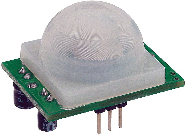
The motion sensor I use in my projects, the Parallax RB-Plx-75, works by sensing changes in the infrared “background” of its field of view (Figure 10-5).
Changes in the infrared signature cause the sensor to output a HIGH signal on its output pin. It’s not so much a motion sensor or an IR sensor as it is a combination of the two. Like the magnetic sensor, it’s really nothing more than a fancy switch, so connecting and programming it is quite simple.
It has three pins: Vcc, GND, and Output. Looking at the sensor from the point of view of Figure 10-5, the pins are OUT, (+), and (-). It can use any input voltage from 3V to 6V, so connect the GND pin to the Pi’s GND, the Vcc to either 3.3V or 5V, and the OUT pin to pin 11 (GPIO 17) for this example. To test our code, let’s connect an LED to signal if the sensor is tripped. Connect pin 13 (GPIO 27) to a resistor, and then connect the positive lead of an LED to the resistor’s other leg. Finally, connect the LED’s negative lead to GND on your Pi. You should now be ready to try the following script:
importRPi.GPIOasGPIOimporttimeGPIO.setwarnings(False)GPIO.setmode(GPIO.BOARD)GPIO.setup(11,GPIO.IN,pull_up_down=GPIO.PUD_UP)GPIO.setup(13,GPIO.OUT)whileTrue:ifGPIO.input(11):GPIO.output(13,1)else:GPIO.output(13,0)
That’s it! When you run the script (remember to use sudo, because you’re accessing the GPIO pins), you should see the LED light when you move your hand around the sensor, and then go out again when there is no movement for a few seconds. Keep this code in your main rover folder.
When working with LEDs, you should always use an inline resistor to limit the current passing through the LED. It’s very easy to burn out an LED, and using a resistor is an excellent habit to get into. Many LED resistor calculators are available online if you aren’t sure what value of resistor to use; I like the one at http://ledz.com/?p=zz.led.resistor.calculator.
I2C Sensors
I2C, also referred to as I-squared-C or Inter-Integrated Circuit, has been called the serial protocol on steroids. It allows a large number of connected devices to communicate on a circuit, or bus, using only three wires: a data line, a clock line, and a ground line. One machine on the bus serves as the master, and the other devices are referred to as slaves. Each device is called a node, and each slave node has a 7-bit address, such as 0x77 or 0x43. When the master node needs to communicate with a particular slave node, it transmits a start bit, followed by the slave’s address, on the data (SDA) line. The slave sees its address come across the data line and responds with an acknowledgment, while the other slaves go back to waiting to be called on. The master and slave then communicate with each other, using the clock line (SCL) to synchronize their communications, until all messages have been transmitted.
The Raspberry Pi has two GPIO pins, 3 and 5, that are preconfigured as the I2C protocol’s SDA (data) and SCL (clock) pins. Any sensor that uses the I2C protocol can be connected to these pins to easily communicate with the Pi, which serves as the master node. If you end up using more than one I2C sensor on your rover, you may find it helpful to add another small breadboard to the rover, with the two power rails running down the side of the board being used for the data and clock lines rather than power.
To use the I2C protocol on the Pi, you first need to enable it by editing a few system files. Start with sudo nano /etc/modules and add the following lines to the end of the file:
i2c-bcm2708
i2c-dev
Next, install the I2C utilities with the following:
sudo apt-get install python-smbus
sudo apt-get install i2c-tools
Finally, you may need to edit your blacklist file, if you have one. (Remember, if it exists, you can find it in /etc/modprobe.d/raspi-blacklist.conf.) If you have one, comment out the following two lines by adding a hashtag to the beginning of each line:
#blacklist spi-bcm2708
#blacklist i2c-bcm2708
Save the file, then reboot your Pi with the following, and you should be ready to use the I2C protocol with your sensors:
sudo shutdown -r now
To see if everything installed correctly, try running the i2cdetect utility:
sudo i2cdetect -y 1
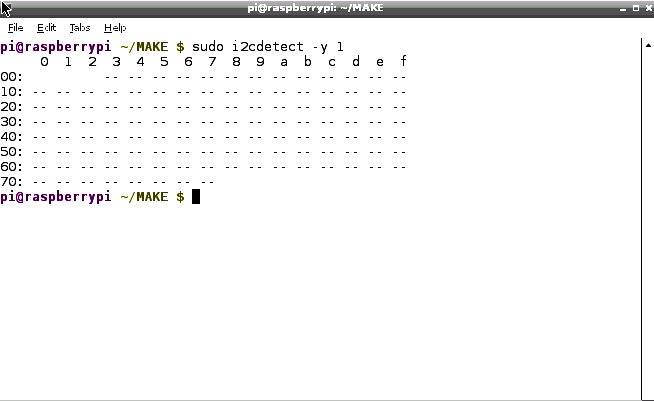
It should bring up the screen in Figure 10-6.
Obviously, no devices are showing up in the illustration because we haven’t plugged any in yet, but the tool is working. If by chance you have devices plugged in but they don’t show up, or if the tool fails to start at all, instead try typing the following:
sudo i2cdetect -y 0
The 1 or 0 flag depends on the Pi revision you happen to have. If
you have a Revision 1 board, you’ll be using the 0 flag; Revision 2 owners will need to use the 1.
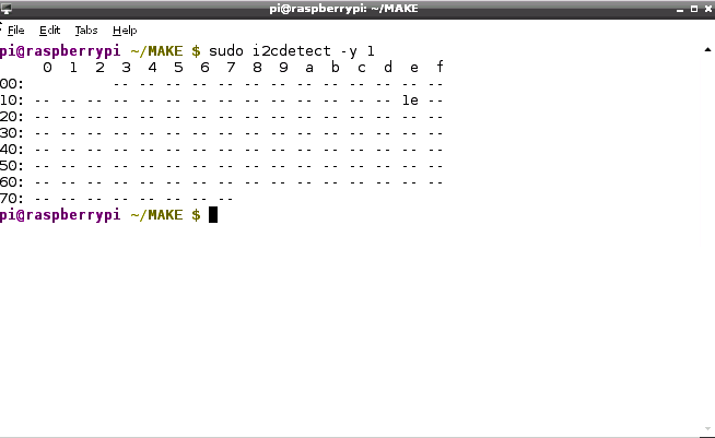
To test the i2cdetect utility, connect an I2C sensor to your Pi, such as the digital compass—the HMC5883L. Connect the compass’s Vcc and GND pins to the Pi’s 2 and 6 pins, and then the SDA and SCL pins to pins 3 and 5,
respectively. When you start the i2cdetect utility, you should now see the results in Figure 10-7, which shows the compass’s (preconfigured) 12C address of 0x1e.
HMC5883L Compass
You have it connected now, so let’s configure the compass. The following script sets up the I2C bus, and after reading the values from the compass, performs a little bit of math wizardry to translate its readings into a format that you and I are used to:
importsmbusimportmathbus=smbus.SMBus(0)address=0x1edefread_byte(adr):returnbus.read_byte_data(address,adr)defread_word(adr):high=bus.read_byte_data(address,adr)low=bus.read_byte_data(address,adr+1)val=(high<<8)+lowreturnvaldefread_word_2c(adr):val=read_word(adr)ifval>=0x8000:return-((65535-val)+1)else:returnvaldefwrite_byte(adr,value):bus.write_byte_data(address,adr,value)write_byte(0,0b01110000)write_byte(1,0b00100000)write_byte(2,0b00000000)scale=0.92x_offset=-39y_offset=-100x_out=(read_word_2c(3)-x_offset)*scaley_out=(read_word_2c(7)-y_offset)*scalebearing=math.atan2(y_out,x_out)ifbearing<0:bearing+=2*math.pi"Bearing: ",math.degrees(bearing)
Here, after importing the necessary libraries (smbus and math), we define
functions (read_byte(), read_word(), read_word2c(), and write_byte())
to read from and write values (either single bytes or 8-bit values) to the
sensor’s I2C address. The three write_byte() lines write the values 112, 32,
and 0 to the sensor to configure it for reading. Those values are normally
listed in a sensor’s datasheet.
The script then reads the x-axis and y-axis values from the sensor and uses the math library’s atan2() (inverse tangent) function to find the sensor’s bearing. The x_offset and y_offset values are subject to change and are dependent on your current location on the Earth’s surface; the easiest way to determine what they should be is to run the script with a working compass nearby to compare values. When you run the script, remember that the side of the chip with the soldered headers is the direction in which the board is “pointed.” Compare the readings and tweak the values of the x_offset and y_offset values until the readings from the two compasses match. Now you can determine which direction your rover is headed. You shouldn’t experience any interference from your Pi or from the motors on your magnetic sensor; the fields generated by those devices are too weak to make a difference in the sensor’s readings.
As always, save this script in your rover’s folder for addition to your main program.
BMP180P Barometer
The BMP180P barometer/pressure chip is another sensor that runs on the I2C
protocol. Again, connect the SDA and SCL pins to either the Pi’s 3 and 5 pins,
or the rails on the breadboard if you’ve gone that route, and the
GND pin to the Pi’s 6 pin. This time, however, connect the Vcc pin to the
Pi’s 1 pin, not the 2 pin. This sensor needs only 3.3V, and powering it
with 3.3V instead of 5V ensures that it will output only 3.3V and not damage the
Pi’s delicate GPIO pins. After you’ve connected everything, run the i2cdetect
utility to make sure that you see the sensor’s address, which should be 0x77.
Like a few of the other sensors, this one needs an external library in order to work, and that library is available from Adafruit. In your terminal, make sure you’re in the main rover folder and type the following:
wget http://bit.ly/NJZOTr
Rename the downloaded file with this command and the library is ready to use, as long as it’s in the same folder as your script:
mv NJZOTr Adafruit_BMP085.py
You’ll also need another script from Adafruit in the same directory,
the Adafruit_I2C library. To get it, in a terminal enter the following:
wget http://bit.ly/1pHgMxF
and then rename it with the following:
mv 1pHgMxF Adafruit_I2C.py
Now you have both necessary libraries. To read from the sensor, create the following script in your rover folder to convert to Fahrenheit:
fromAdafruit_BMP085importBMP085bmp=BMP085(0x77)temp=bmp.readTemperature()pressure=bmp.readPressure()altitude=bmp.readAltitude()"Temperature:%.2fC"%temp"Pressure:%.2fhPa"%(pressure/100.0)"Altitude:%.2f"%altitude
The Adafruit library is nice because it handles all the intricacies of
communicating over the I2C bus for us; all we have to do is call the functions readTemperature(), readPressure(), and readAltitude(). If you’re not in one of the 99% of countries using Celsius for temperature, just add the following line:
temp = temp*9/5 + 32
Nintendo Wii Devices
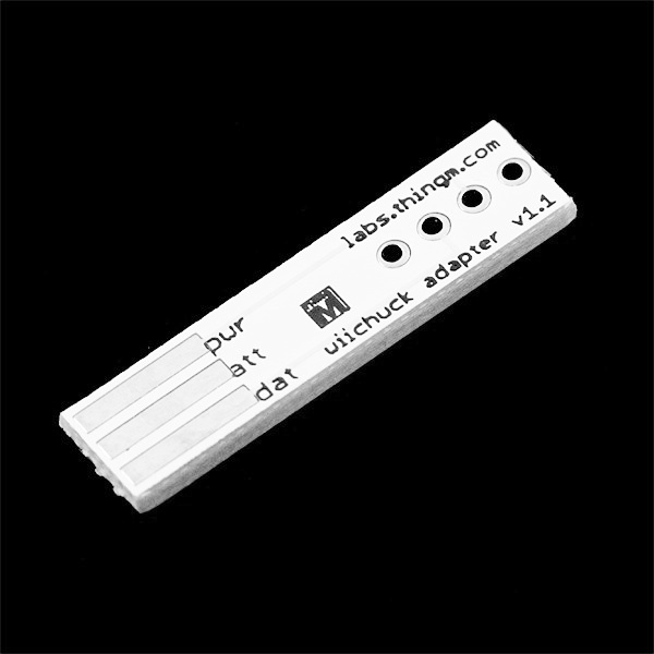
You can also use the I2C library to communicate with other devices, of course; it’s not unheard of to connect a Nintendo Wii nunchuk to the Pi with a special adapter, called a Wiichuck adapter (Figure 10-8).
You can then read the values from the nunchuk’s joystick, buttons, and onboard accelerometer to control things like motors, cameras, and other parts of the robot.
Camera
The last thing we need to go over is the Pi’s camera; it is technically a sensor, and you can use it to take pictures of your rover’s surroundings and even stream a live feed over the local network and navigate that way.
Hooking up the camera is fairly straightforward. If you’re sticking with the flex cable that came with the camera, you’re almost finished already. Insert the flex cable into the small connector between the Ethernet port and the HDMI connector. To insert it, you may have to pull up slightly on the tabs on both sides of the connector. Insert the cable with the silver connections facing the HDMI port, as far as it will go, and then press down on the edges of the connector to lock it into place.
If you’re using an extension cable such as the one from BitWizard, follow their instructions as to hooking up the flex and the ribbon cables. When you’re finished connecting the camera, enable it in the raspi-config file if you haven’t done so already by typing the following and enabling it there (option 5):
sudo raspi-config
Once enabled, to test the camera, open a terminal window and type:
raspistill -o image.jpg
After a short pause, image.jpg should appear in the current directory.
Raspistill is an amazing program. Technically, all it does is take still pictures with the Raspberry Pi camera module. In reality, it has a whole series of options, including the ability to take time-lapse sequences, to adjust image resolution and image size, and so forth. Play around with the flags listed on the Raspberry Pi site’s camera documentation page.
To use the Python library now available for the camera (Python 2.7 and above), enter the following in your terminal to install it:
sudo apt-get update
sudo apt-get install python-picamera
You’re now ready to use the camera. If you plan to place the camera in the robotic arm attachment, refer back to Chapter 7 as to how to mount it there. Then you can use it with the Python library with a script such as this:
importpicameracamera=picamera.PiCamera()camera.capture('image.jpg')
This will simply capture image.jpg and store it in the local directory. One nice thing about the Python library as opposed to the command-line interface is that the default image size for the Python module is much smaller than the command-line default.
If you would like to record video with the camera, it’s as simple as this:
importpicameraimporttimecamera=picamera.PiCamera()camera.start_recording('video.h264')time.sleep(5)camera.stop_recording()
This will record for 5 seconds and then stop.
Live camera feed
All of these are nice if you simply want to travel to a point and then take pictures or video after you arrive. But what if you would like to navigate using the feed from the camera? This, too, is possible, by streaming the video feed from the camera over the local ad hoc network you’ve set up and playing the stream on the computer you’re using to remotely control the Pi. To do this, you’ll need the VLC media player installed on both the Pi and your control computer. On the Pi, it’s a simple:
sudo apt-get install vlc
to install it; on your controlling computer, VLC is available for Linux, Windows, and OS X.
The stream will be broadcast using Real Time Streaming Protocol (RTSP). This protocol is a common network video-streaming interface, and VLC is easy to set up to both transmit and receive and decode it. Once VLC is installed on the Pi, start the stream with the following:
raspivid -o - -t 0 -n -w 600 -h 400 -fps 12 |
cvlc -vvv stream:///dev/stdin --sout
'#rtp{sdp=rtsp://:8554/}' :demux=h264
Then move to your control computer, open VLC, and open a network stream from
rtsp://<Your Pi IP>:8554. It’s a small, 600 x 400 window, so not too much
bandwidth should be needed. There’s also likely to be a delay of several
seconds, so this may not be an optimal way of controlling your rover in a
situation where fast response times are important.
You may run into the problem of your Pi shutting down as soon as you issue the streaming command shown here. It seems that the command draws a lot of power—sometimes, enough to shut everything off. If that does happen, try a different power supply (if you’re powering the Pi from a USB wall charger) or a different battery pack (if you’re using batteries such as the Li-Poly battery pack). Experimentation is always helpful; I had success simply by using a shorter USB power cable at one point.
If you can’t get it to work, your particular Pi/power/VLC combination may just be too ill-suited for live streaming video. In that case, you’ll just have to remain in view of your rover to control it—which is not the end of the world.
That by no means covers all of the sensors that are available for your rover, but it should give you a pretty good start. Many sensors are just switches at heart, and if not, there may be a library available to read from them. Or they may follow the I2C protocol, making them easy to add to your rover’s sensor network. In the next chapter, we’ll cover putting all of these snippets of code together and controlling (and reading from) the rover by using one program.
