Chapter 8. UV Unwrapping
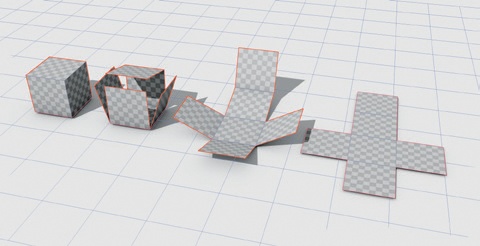
In this chapter, we’ll UV unwrap the models created so far (where necessary). UV unwrapping describes the process of creating a set of 2D coordinates for the faces of a model, which we can then use to apply textures to the model. Creating UV coordinates is akin to cutting up the surface of your model (along lines called seams) and spreading it out flat (see Figure 8-1). As you know, a mesh in Blender is made up of vertices joined together to form edges and faces. Each vertex in a model has its own set of spatial coordinates in the three spatial dimensions of the 3D Viewport: x, y, and z. These coordinates determine its position in 3D space. Similarly, UV coordinates are a separate set of 2D coordinates for the points of a model that allow you to map a 2D image to the surface of your mesh.
Other Kinds of Texture Coordinates
UV coordinates are only one way of mapping an image to an object in Blender. Blender also has a number of procedural coordinates that you can use to assign textures by applying some kind of projection to your mesh. These have the advantage of being automatic and are useful for a wide range of applications, but they lack the precision of UV unwrapping, which allows you to specify exactly which points on the mesh correspond to the parts of an image.
Editing UV Coordinates
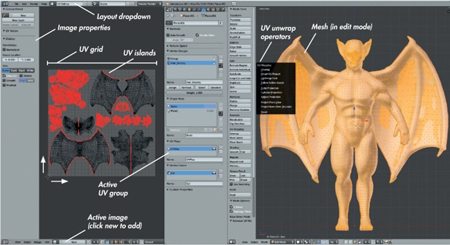
To edit UV coordinates, we use Blender’s UV Image editor along with the 3D Viewport. In general, when working with UV coordinates, it’s useful to switch to Blender’s UV editing layout using the drop-down menu in the Info editor header (see Figure 8-2). This brings up the UV Image editor shown on the left and the 3D Viewport on the right.
It’s helpful to add a Properties editor between the UV Image editor and the 3D Viewport by rightclicking the border between them and choosing Split Area. When you set the new area as a Properties editor, you can access the Object Data tab for switching between different UV coordinate sets and the Render tab for accessing Texture Baking controls.
The UV Grid
We’ll use the UV Grid in the Image editor to determine which portion of a texture or image is applied to part of a mesh. The grid has coordinates that run from 0 to 1, with the origin at the bottom left. By default, these coordinates are multiplied by the size of the image you select in order to give a number in pixels. If you have no image selected, Blender will assume the grid is 256 pixels across and give coordinates on that scale. You can turn this feature off by pressing N to bring up the Properties region of the UV Image editor and checking Normalized in the Display panel, which will then give UV coordinates between 0 and 1. The UV Image editor follows the same conventions as the 3D Viewport: You can move, rotate, and scale any selected vertices using the same keys as in the 3D Viewport, and you can use the X and Y keys to constrain operators to the horizontal and vertical axes of the UV grid. By default, a mesh will not have any UV coordinates, so there will be nothing to select until you unwrap it.
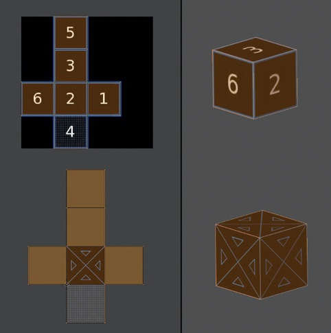
When you map an image to a mesh using its UV coordinates, the image is scaled to fill the UV grid, and each point of the mesh is then mapped to the corresponding point in the image. Beyond the edges of the UV grid, the image is repeated or extended so that UV coordinates outside the grid are mapped to part of the image as well. This allows you to repeat a tileable texture (one that can be repeated side by side and top to bottom without any discontinuity) over the surface of your mesh by unwrapping the mesh to be much bigger than the UV grid. Conversely, you can unwrap a whole mesh (or even multiple meshes) so that all the UV coordinates fit within the UV grid and then use a single (nontiling) image to uniquely texture each part of the object’s surface. Both options are shown in Figure 8-3.
When creating objects with fairly repetitive or homogenous textures, such as brick walls or soil, tileable textures can save you a lot of time. On the other hand, when creating characters and other unique objects, you’ll need to pack an object’s UVs onto a single grid in order to texture each part differently.
Unwrapping Tools
To start unwrapping a model, you’ll need to be in Edit mode (press TAB to switch into it if you aren’t already there). You’ll probably also want to switch to Edge Select mode in the 3D Viewport header, as tagging edges with UV seams is easiest when you can select edges directly. To begin unwrapping your object, press U in the 3D Viewport, which will bring up several operators for unwrapping your object, as shown in Figure 8-2. These operators are as follows:
Unwrap. This is probably the most useful UV unwrapping method. Blender will try to unwrap your mesh by flattening it as if it were made from stretchy fabric, while also trying to minimize the distortion that this flattening inevitably causes. (In order for this process to work for a closed mesh, you’ll need to mark some UV seams on your mesh.)
Smart UV Project. This will automatically project your mesh by first projecting the largest chunk possible from one angle, excluding invisible faces or ones that point away from that viewport. It will then project progressively smaller, more difficult parts, splitting them into different UV islands as it goes. This effect can work reasonably well for simple meshes, but when used with more complex shapes, it often produces a lot of little islands that can be difficult to work with.
Lightmap Pack. This special UV unwrapping option for baking lighting to textures projects each individual polygon in a mesh to a separate rectangular UV island. The Lightmap Pack option uses up the UV coordinate space very efficiently, which makes it useful for baking lighting textures for game engines but not very useful for practical texturing.
Follow Active Quads. This follows the active quad (the one highlighted when you have multiple faces selected in Face Select mode—usually the most recently selected one) and unwraps the faces radiating out from it in an even grid. This option works particularly well for meshes with grid-like topology (that is, no poles), such as pipes, cylinders, flat(ish) grids, and the like. It works best when you unwrap one quad first as a perfect rectangle with 90-degree corners: 1) Unwrap with U▸Unwrap; 2) select each edge of the unwrapped quad in the UV Image editor and scale it so it’s perfectly horizontal/vertical; 3) unwrap the rest of the mesh by selecting it with CTRL-L, which selects anything connected to your current selection; 4) use the Follow Active Quads unwrap operator to get a nice even unwrap. This option, though, doesn’t work well for meshes with more complex topology.
Cube Projection. This option projects the faces of your mesh as if on the surface of a cube. It’s useful for roughly cube-shaped objects.
Cylinder Projection. This option works like Cube Projection but acts as if the mesh is cylindrical.
Sphere Projection. This option also works like Cube Projection but acts as if the mesh is spherical.
Project from View. This option projects your mesh as it appears in the 3D Viewport. It’s particularly useful for projecting a small, flat part of your mesh before pinning it and then projecting the rest using the Unwrap operator.
Project from View (Bounds). This option works like Project from View, but after it projects the meshes, it stretches the UV coordinates to fill the whole UV-coordinate space.
Reset. This option stretches each face across the whole UV-coordinate space.
Seams
Imagine trying to flatten out a beach ball. Even once you deflate it, you can’t stretch it out so that each part of the surface is flat on the ground without making at least one cut to the ball, and the more you carve it up, the less you have to stretch and distort it in order to flatten it out. Something similar is true when using the Unwrap operator to unwrap a mesh. In order for the operator to work, you’ll need to mark edges as seams where the mesh will split. Ideally, you should mark as few seams as possible so that you won’t have to paint across too many seams when it comes to texturing, but you also need to mark enough so that your mesh will not be distorted by the UV unwrapping. Distortion in this case arises from Blender having to warp and stretch the geometry in order to lay it out flat. When you use the distorted UVs to map an image to the 3D object, the texture will look stretched out as well.
To mark UV seams, select edges in Edit mode and use CTRL-E▸Mark Seam to mark the edge as a UV seam. To quickly select the shortest path between two edges (a good way to select a long string of edges for marking), select one edge, then press CTRL and rightclick the edge you want to use as the end point. You can also press ALT and rightclick to select an entire edge loop at once, allowing you to mark multiple edges at the same time. Shortcuts like these will make tagging multiple edges at once much quicker.
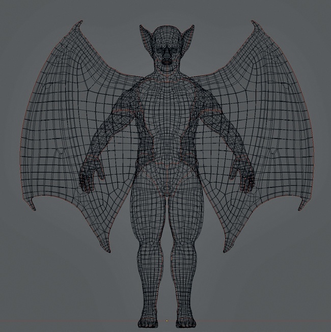
In general, you should try to hide your UV seams in areas where they won’t cause problems and where they will minimize the amount of stretching in your unwrap. Valleys and creases in your mesh are good places to hide seams, as is any area that won’t get too much attention. Try to mark seams symmetrically to make it easier to understand your unwrap and to allow you to copy and paste elements of your texturing later (if your unwrap is symmetrical, too). Finally, split your mesh into sensible islands (groups of faces bounded by seams). For example, in the case of the Bat Creature, I split the torso, wings, head, arms and legs, and hands and feet into separate sections, as you can see in Figure 8-4.
Pinning Vertices
Unwrapping your mesh with the Unwrap operator may not give you exactly the unwrap you want; for example, one area might be scrunched up or have a proportion that’s not to scale. To fix this, you can pin vertices in the UV Image editor so that they won’t move when you re-unwrap the mesh (shortcut E in the UV editor or U in the 3D Viewport) by selecting a vertex or vertices and pressing P to pin them. (Pinned vertices will be highlighted in red.) Now when you re-unwrap, Blender will keep the pinned vertices in place and stretch the rest of the unwrap to allow for this. To unpin vertices, select them and press ALT-P.
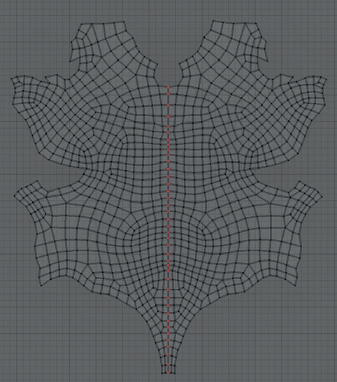
One important reason to use pinning is to establish a symmetrical unwrap. To do this, unwrap your mesh and then select a string of vertices running down the middle of the mesh and align them in the UV Image editor so that they are in a straight line (running in the appropriate direction). An easy way to do this is to scale them to zero on the x- or y-axis and then pin them (P). Now press E in the UV editor to unwrap again. This gives you a more symmetrical unwrap, as shown in Figure 8-5.
Pinning can also be used to fix areas on large meshes that unwrap on top of one another, as often happens with long, tube-like meshes, where the UV unwrap may coil around undesirably. To fix this problem, pin one vertex from each end of the mesh so that the vertices sit farther apart in UV space, then unwrap the mesh again.
Finally, when unwrapping a mesh with a lot of different pieces, it can help to pin entire UV islands as you finish with them so that you can move on to unwrapping other pieces without disturbing the ones you’re happy with. Blender will re-unwrap anything you have visible in the UV Image editor by default when you re-unwrap, so this is a good way to keep finished parts of your unwrap safe.
Packing
When unwrapping characters and other unique objects, it’s often helpful to pack all of the UV islands for your mesh into a single grid. To do this automatically, you can use the Pack operator (CTRL-P), but you can usually do a more efficient job of packing UV islands yourself simply by moving, scaling, and rotating them like puzzle pieces. To speed up the selection of whole islands, switch to Island Selection mode in the UV Image editor using the buttons in the header.
When packing UV islands, be sure to keep the scale of the islands similar. To average the scale of any UV islands you have selected, use CTRL-A or scale the islands manually. It’s much easier, though, to see whether islands are scaled correctly once you have a UV test grid assigned (see Testing Your UV Coordinates).
Assigning UV Textures
There are many ways to display textures on your models. For one, you can use Blender GLSL materials to create advanced materials with Texture options that respond to lighting and transparency. For simpler applications, though, such as previewing how a single image will be mapped to an unwrapped object, you can assign that image to your model in the UV Image editor. To do so, take the following steps:
Select the object and enter Edit mode.
Select all of the faces and unwrap them if you haven’t done so already.
Select the image you want to assign to the mesh from the image drop-down menu in the header of the UV Image editor. Alternatively, you can open an image with Image▸Open Image, or create one with Image▸New Image.
To see your image in the 3D Viewport, go to the Display panel of the Properties region and enable Textured Solid.
Testing Your UV Coordinates
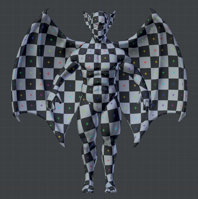
To make sure that your UV unwrap works well and that areas are not becoming too distorted, apply a UV test grid to see the effects of your unwrap on your mesh (see Figure 8-6). To do so, follow the steps below:
In the UV Image editor, with your object in Edit mode, click Image▸New Image to apply a new image to your mesh and check the UV Test Grid option. This will generate a test grid pattern and assign it to the UV coordinates of your mesh.
Turn on Textured Solid in the display options of the Properties region in the 3D Viewport. You should see a checkerboard pattern applied to your mesh.
You should now be able to easily see problem areas in your unwrap, such as areas with awkward stretching or parts of the mesh that are too big or too small. You can then fix these areas in the UV Image editor and see the changes in real time in the 3D Viewport.
Unwrapping the Bat Creature
As you’ve seen in the preceding discussion, I unwrapped the Bat Creature and packed it into a single UV tile by first tagging seams and then unwrapping with the Unwrap operator (see Figure 8-7). For the torso, I made the unwrap more symmetrical by selecting the line of vertices that ran down the middle of the front of the torso in the UV Image editor, scaling them on the x-axis to zero (S▸X▸0), pinning them, and then unwrapping again (E). Next, I averaged the scale of all of the islands, packed them into the UV grid, and scaled up the head slightly to give it more texture space relative to other areas (because it’s the part of the body likely to get more attention). Finally, I unwrapped the fingernails and teeth onto the same layout, fitting them into the remaining gaps between the other islands.
For the eyes, I unwrapped only the inner mesh simply by positioning the 3D Viewport to look at the eye straight on and using the Project from View (Bounds) operator. Later on, I will tweak the UVs of the eye mesh to fit the texture I will paint for it. See Chapter 11 for more on unwrapping and texturing the eyes.
Unwrapping the Jungle Temple
The Jungle Temple had many separate elements, and rather than go through them all, I’ll just cover the most difficult ones. (The objects in the Jungle Temple not discussed below are simply unwrapped using variations on the techniques discussed earlier.)
Stone Blocks
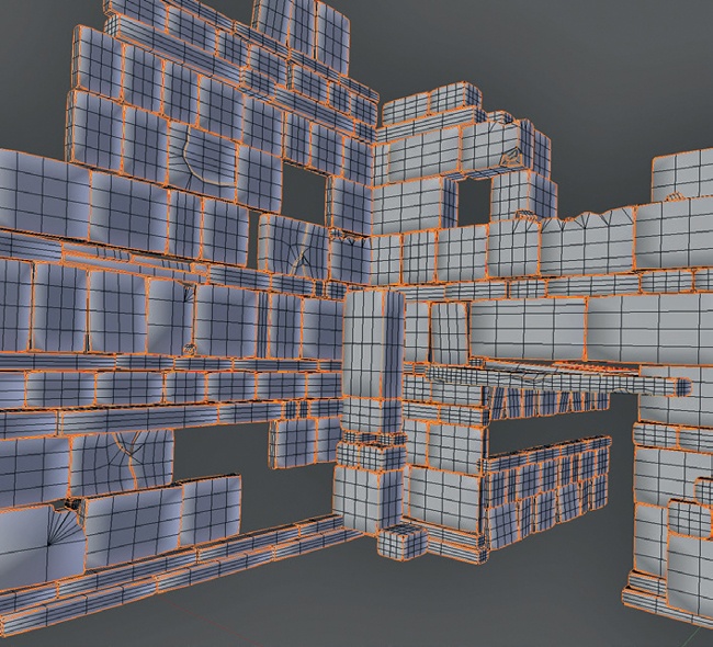
There were an awful lot of stone blocks in the Jungle Temple, so I didn’t want to have to texture each individually. Instead, I wanted to be able to unwrap them all relatively quickly and reuse the same textures for each. My quick and dirty solution was to use the Select Sharp operator in Edit mode to select the sharp edges of the blocks (Select▸Sharp Edges from the 3D Viewport header) and then mark them as seams (see Figure 8-8). Next, I used the Unwrap operator to unwrap all the blocks at once. I manually removed some seams in areas like the damaged stone and at the edges of some blocks where I wanted the texture to wrap around rather than having an obvious seam. I only placed seams manually on the blocks in the scene’s foreground, and I unwrapped these manually to make sure they unwrapped nicely.
Trees
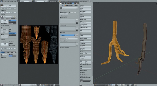
In the case of the trees, I added seams down their backs (the sides facing away from the camera) and around the joins between the trunk and the roots. I then unwrapped them using Unwrap. Next, I selected a string of vertices in the UV Image editor that ran down the middle of the root or trunk, aligned it with the vertical axis, and pinned it. Unwrapping again gave me nicely aligned UV islands.
The technique described above is useful when unwrapping something like tree bark that has a texture with a strong grain or directional pattern because all of the pieces will align with the direction of the grain. I packed both trees into the same UV space (see Figure 8-9) to allow me to texture them both at the same time later on.
Multiple UV Maps
You can add multiple UV-coordinate sets to an object and edit them independently. This is good for making use of multiple textures in complex materials and when texture painting. When texture painting, you can use one UV set to neatly pack your UV islands for your final texture and use another to assign seamless textures or photos to clone texture information from. In subsequent chapters, I will sometimes refer to creating extra UV sets for purposes like these.
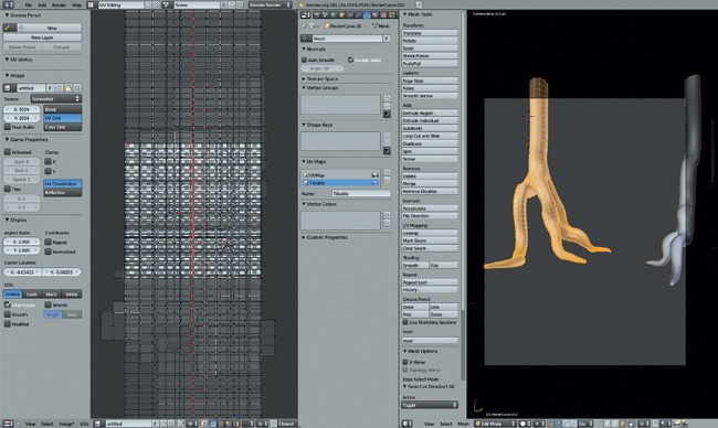
For the trees, I created a second UV coordinate set to match up with a tileable bark texture, saving the first UV set to use for baking ambient occlusion and the final texture maps. To create this second set, I opened the Object Data tab of the Properties editor and clicked the + icon in the UV Maps panel to create a new UV set. You can choose between your existing UV sets from this panel and edit whichever is active. To unwrap the second UV set for my tree, I used the Follow Active Quads operator for the parts of the trees with approximately cylindrical topology and unwrapped and packed them so that they filled the width of the UV grid (see Figure 8-10). Later, this would allow me to tile a texture multiple times around and along the length of the trunk and roots without creating too many seams where the textures didn’t match.
Sharing UV Space Between Objects
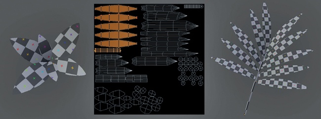
Just as you’ll usually want to combine all of a single object’s UV islands in the UV grid, when it comes to unwrapping multiple objects for texturing, you may want them all to share the same UV space so that they can all use the same texture. Doing so will save you time when painting textures and memory when rendering. To see the UV coordinates of multiple objects in the UV Image editor at the same time, select the objects and then enter Edit mode for the one you want to edit. In the UV Image editor, turn on View▸Draw Other Objects. The UV coordinates for the selected objects will now be visible in gray (though only the current object will be editable), allowing you to align multiple objects on the same UV grid (see Figure 8-11).
Leaves and Grass
Flat meshes with open edges are particularly easy to unwrap because you don’t have to mark any seams. I simply used Unwrap on all the leaves in my scene, unwrapping them all to share the same UV space (see Figure 8-11). This excludes the IvyGen leaves, which were automatically unwrapped by the IvyGen add-on already. For the cylindrical elements, such as the stems of the grass, I marked seams as needed, unwrapped one face (making sure it unwrapped as a rectangle), and then selected the rest of the mesh (CTRL-L) and unwrapped using Follow Active Quads.
Statue
For the statue mesh, I marked seams by hand around all the major parts and unwrapped using the Unwrap operator. Figure 8-12 shows the results. You could try using Smart Unwrap, and you might get what you need for a mesh like this, but unwrapping by hand will always give you more control.
The Rest of the Elements
The other elements in the Jungle Temple scene were all pretty straightforward and followed the same strategies used so far. Some elements, like the water, didn’t need UV textures because they will use entirely procedural materials instead. (Chapter 9 will deal with creating procedural materials that don’t require textures, such as water and glass.)
Unwrapping the Spider Bot
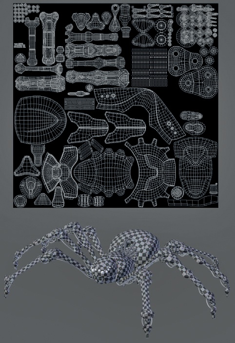
For the Spider Bot, I did my best to squeeze the model’s entire UV unwrap onto a single texture (see Figure 8-13), excluding a few parts that would receive only procedural materials. Because much of the model used similar materials, it was easy to edit the whole texture at once. By starting with the big elements, like the body and the legs, and then squeezing the smaller parts into the gaps in between, I could produce a very efficiently packed set of UVs, ensuring that important elements got the texture real estate they needed. You can always check that the different parts unwrap with the right scale and without stretching using a UV grid texture (see Figure 8-13).
Applying Modifiers and Duplicates
In previous chapters, I used modifiers to model and retopologize the Spider Bot’s body and legs symmetrically. By doing so, I reduced the amount of work required and duplicated some of the parts for the legs. While I could have kept the leg pieces as duplicates, it was better to apply some of the modifiers at this stage, especially Mirror modifiers, because otherwise the textures would be mapped to both sides of the objects symmetrically. This would result in some obvious symmetry down the middle of the objects; worse, if I were to use any text or graphics in my textures, they would appear on the mirrored side of the mesh backward! For this reason, I applied the Mirror modifiers assigned to many of the Spider Bot’s constituent objects.
Unfortunately, Blender won’t allow you to apply modifiers to objects that share their mesh data with other objects. This makes applying modifiers to the model difficult when, as for the Spider Bot, I have used linked duplicates to copy parts of the model, like the legs, which now have many objects that share the same mesh data. To get around this, use the Mesh from the Curve/Meta/Surf/Text operator (ALT-C), which will apply any modifiers to an object and convert them to proper geometry. Because you want to apply only the Mirror modifier, not the Subdivision Surface modifier, remove all but the Mirror modifier first and then use the operator. You will then need to remove the Mirror modifiers from the other duplicates because they will now be using the already mirrored mesh data.
Sharing UV Space Efficiently
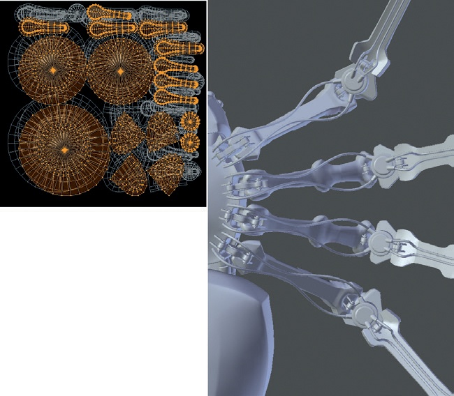
For certain areas, I shared the UV space for similar parts (see Figure 8-14). For example, for the mechanical elements beneath the legs, I placed all of the UV islands on a patch at the top-right corner of the UV grid. Doing so will cause errors when baking textures, but by painting a generic texture over these areas, I can texture multiple parts of the model without using as much UV space. (Since these parts are relatively hidden, the lack of unique textures on these areas won’t make too much of a difference.)
Making sure that all objects are assigned roughly the same amount of UV space according to their size is more difficult for multiple objects because the Average Islands Scale operator (CTRL-A) works only on UV islands within a mesh. However, by using a UV grid texture and enabling Textured Solid in the 3D Viewport, you can judge the scale of an object’s UV coordinates and adjust them accordingly.
In Review
This concludes unwrapping the models I created in earlier chapters. We’ve looked at how to tag seams to unwrap meshes and how to refine the results of Blender’s unwrapping. We’ve also learned how to pack UV coordinates for meshes together to make it simple to texture multiple objects with one image. In Chapter 9, we’ll move on to adding particle systems to some of our projects to create fur and grass before baking and painting textures in Chapter 10 and Chapter 11 and creating materials in Chapter 12. In these later chapters, we’ll apply images to the UV coordinates we created in this chapter in order to bake and paint on textures that we can then use as the inputs for materials.
