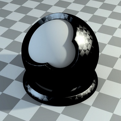
Chapter 12. Materials
In Chapter 10 and Chapter 11, I created textures that specified the diffuse colors for the models, as well as other parameters, like reflectiveness, smoothness, and specular colors. Now we’ll look at combining these image textures with procedural textures and shaders to create materials for the scenes that look both interesting and convincing.
This chapter will cover how Blender’s materials work and how to incorporate textures into these materials. Let’s look first, though, at Blender’s two default render engines for rendering images, Cycles and the Blender Internal renderer, as they will significantly impact how we set up our materials.
Render Engines: Blender Internal and Cycles
The render engine is how Blender creates a final image using all of the information in your scene—objects, materials, lights, and settings. Blender has two render engines. The older one, the Blender Internal render engine, is a very robust (if slightly old-fashioned) renderer that uses various tricks and techniques to create the final render, eschewing absolute physical accuracy for speed and flexibility. However, this lack of physical accuracy doesn’t mean that Blender Internal can’t render realistic-looking images. It can quickly render scenes with a variety of complex materials to create a final look anywhere between a highly realistic aesthetic and a very nonphoto-realistic and stylized one. This makes Blender Internal a highly flexible renderer, well suited to animation.
Cycles is Blender’s new render engine, which is still in active development. Unlike the internal engine, it focuses on creating more realistic simulations of light and uses more physically correct models for materials and lights. As a result, it can deliver very realistic images, including effects that are difficult to achieve in Blender Internal, such as the complex refraction of light in glass and other transparent objects, multiple reflections of light bouncing around a scene, and the physically correct emission of light from objects. The tradeoff is that (at least as of this writing) Cycles renders scenes—even those with simple lighting—more slowly than Blender Internal. And because Cycles is in active development, it lacks certain important features, like subsurface scattering (see Subsurface Scattering for more information) and the ability to render hair and fur.
I’ll use both renderers in this book. Which renderer I choose for each project has a significant impact on how I define my materials, because these two render engines work in different ways and require materials to be set up differently. For the Bat Creature, I’ll use Blender Internal to render realistic skin with subsurface scattering, as well as the fur. And for the Spider Bot, though either renderer would do, I’ll use Cycles to create some nice glossy, reflective materials. For the Jungle Temple project, I’ll use Cycles to allow me to experiment with lighting and get direct feedback, thanks to Cycles’ interactive render preview (discussed in The Cycles Render Preview).
Before examining the differences in creating materials for the two different render engines, let’s take a brief look at a few general principles that will come up as we discuss materials. These principles center mainly on the various ways a surface can interact with light by reflecting, refracting, or absorbing it.
Reflection
We see objects because our eyes detect the light that bounces off them. The appearance of a surface is thus determined by the precise way in which it interacts with light, which is in turn determined by the structure and composition of the material.
In the real world, matte surfaces, like rock and rubber, have a rough structure on a microscopic scale. Light bounces off them in all directions, and as a result, the light you see reflected looks much the same no matter which direction you look at the surface from. This is called diffuse reflection.
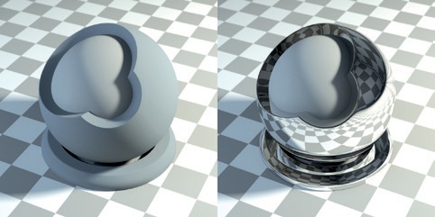
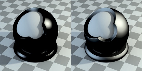
In contrast, polished surfaces are relatively smooth, even at microscopic scales. This means that you’ll see a perfect reflection when you look at the surface, and as you move your viewpoint, what is reflected will change. This is called specular, or mirror, reflection. The differences between diffuse and specular reflection are shown in Figure 12-1.
In the world of CG, however, we often take shortcuts to achieve the look of real materials. For example, consider specular reflections: While it’s possible to render mirror reflections, doing so is slower than rendering diffuse reflections because there are simple algorithms to approximate the effect of diffuse reflections. So rendering diffuse reflections can be extremely fast, but rendering mirror reflections requires processor-intensive ray tracing. To get around this problem, we sometimes consider only the most obvious things that a surface can reflect, like bright lights. For example, if you were to look at a shiny metal surface in bright light, you might overlook mirror reflections of the surrounding environment due to the very bright reflection of the light source itself. Specular reflections work this way in Blender’s Internal renderer: The renderer creates only highlights from light sources rather than making the surface reflect other objects around it (see Figure 12-2). This shortcut often does the job, and when more accurate reflections are needed, you can turn them on as well (by enabling ray-traced mirror reflections) at the cost of extra rendering time.
Transmission and Refraction
In addition to reflecting light, surfaces like water or glass also transmit light (allow light to pass through them). In the real world, a part of the incident light (light hitting the surface) is usually reflected, and the rest is transmitted and bent slightly (refracted). The light is bent because as it enters a different medium, its speed changes. This bending of light results in a distorted image when you look through a transparent material. The amount of distortion depends on the object’s index of refraction (IOR), which determines how much the direction of a ray of light is altered at the boundary of the object (see Figure 12-8), and the shape and thickness of the object. For some objects, this effect is significant—for example, when you look through a lens or a glass of water, you’ll notice considerable distortion. Other times, the effect is minimal—for example, there is little distortion when you look through the thin glass of a window.
Z Transparency
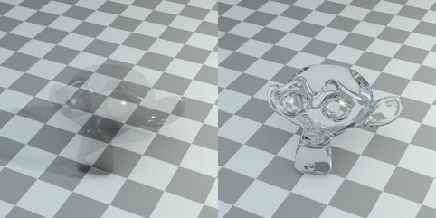
We can use Blender to simulate transmission and refraction of light using ray-traced transparency. But we can also cheat by ignoring refraction and simply rendering whatever is behind an object. This is called Z Transparency. This technique works well with objects like windows, where the refraction is minimal. Figure 12-3 compares ray tracing with Z Transparency.
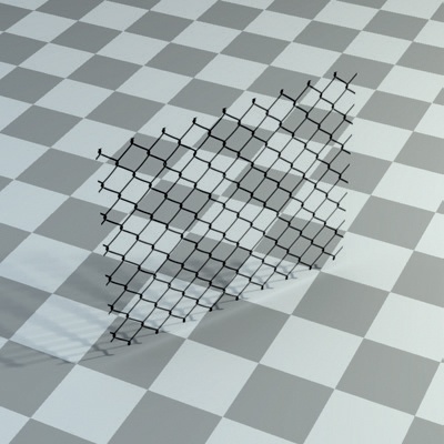
Z Transparency is also useful for rendering thin surfaces with holes or complex outlines, where the mesh can be left simple and a texture can be used to define transparent—or, in this case, nonexistent—areas of the surface. These areas can then be rendered completely transparent (invisible), which will make the surface appear more complex than its geometry alone would allow (see Figure 12-4).
Light can interact with a surface in still more complex ways, such as scattering beneath the surface or exhibiting translucency or anisotropic reflection, which is the type of reflection produced by brushed metal. We’ll examine these other types of interaction as we move through this chapter.
Blender Internal Materials
Blender Internal is Blender’s default render engine, and you can create materials for Blender Internal using the Materials and Textures tabs of the Properties editor. You can find the properties of materials in the Material tab (and the textures and aspects of a material they can be used to affect) in the Textures tab.
Blender Internal’s materials are pretty modular, allowing you to add and combine different material properties—such as specular reflections, mirror reflectivity, transparency, and subsurface scattering—simply by turning on the relevant options from the different panels in the Material tab (Figure 12-5), without having to start from scratch. Notice in the figure that all of the materials assigned to the active object are in the panel at the top of the tab. Below, in the Preview panel, is a preview of the active material, followed by other panels containing the Materials settings. I’ll discuss the relevant panels in the Materials tab (when using Blender Internal) here.
Diffuse. This panel contains the settings for the diffuse color and shading of a material. The color picker (see Figure 12-5) allows you to set the diffuse color of the material, which is then multiplied by the intensity value. The dropdown menu to the right lets you set the diffuse shader model, which affects the falloff of the material’s diffuse color from light to dark at different angles. The default Lambert shader model is usually fine, though the Oren Nayar shader model can be used to mimic surfaces with a rougher microscopic structure, like clay or stone. The other shader models here are more exotic and rarely useful.
Specular. The settings in the Specular panel are similar to those in the Diffuse panel, except that they control an object’s specular shading (a loose approximation of specular reflection, as discussed earlier in Reflection). The hardness entry determines how broad or tight these reflections are (see Figure 12-6). Materials with a high hardness value have sharp, bright highlights, while those with a low hardness value have softer, more spread out highlights.
Shading. The following options affect a material’s overall shading:
Emit. This causes an object to appear bright even when it is not lit and can even cause an object to cast light on other objects when it is used with certain World settings.
Ambient. This determines whether an object receives ambient illumination (using the Ambient Color setting in the World Settings tab).
Translucency. This causes an object to appear lit on both its front and back, making it look translucent, like thin paper or a leaf.
Shadeless. This completely eliminates the effect of light on an object; the object will get its color and brightness entirely from its diffuse color and textures.
Tangent Shading. This alters the shading of a surface to more closely resemble that of brushed metal or other materials with a “grain” or directionality to their microscopic structure. The direction of the grain is taken from the object’s UV coordinates, so the grain will be aligned with the v-axis in UV space. In other words, it will be aligned vertically in the UV Image editor, so ensure you have unwrapped the object appropriately when enabling this option.
Cubic Interpolation. This alters how the surface blends between light and shadow, usually with smoother-looking results though often slightly darker.
Transparency. Turn on the Transparency checkbox to render a material with transparency. This panel offers three ways to render transparent objects, using the surface’s alpha value. The simplest, Mask, simply blends the material into the background where the color is transparent. Z Transparency is slightly more sophisticated, rendering whatever is behind the transparent object. Ray-traced Transparency calculates proper refraction. Choosing Ray-traced Transparency brings up a variety of options that allow you to set the index of refraction of the material and the glossiness and amount of filtering done by the material.
Mirror. Enable Mirror to turn on rendering ray-traced reflections. The settings in this panel let you define the amount (Reflectivity) and sharpness (Glossy Amount) of ray-traced reflections.
Subsurface Scattering (SSS). This option controls the effect of light scattering under the surface of a material commonly found in skin or wax. I’ll discuss this in more detail in Subsurface Scattering.
Options. This panel contains some miscellaneous options. For example, the Traceable setting controls whether an object is taken into account when rendering ray-traced shadows and reflections. I’ll cover these when they come up, and you can look up any I don’t mention on the Blender wiki (at http://wiki.blender.org/).
Shadow. This panel controls how an object receives and casts shadows. For example, the Cast Only option makes an object appear invisible except for any shadows it casts. Shadows Only renders a material’s shadows as the only nontransparent parts. (This is particularly good for creating shadows that you can then composite into another image.)
Cycles Materials
Unlike the Blender Internal renderer, which is packed with dirty tricks and approximations to make rendering quicker, the Cycles renderer uses more physically realistic models for materials. It combines realism with a node-based approach that focuses on building up complex materials from simple parts. You can still use the Materials tab of the Properties editor to edit Cycles materials, which gives an overview of the current material, but it’s much simpler and clearer to use Blender’s Node editor, as shown in Figure 12-7.
To create a material with Cycles, all you need is a Shader node and Material Output node. You can build out from there and combine other shaders, inputs, and textures to create a wide variety of materials. To add a node, use SHIFT-A and choose the node you want from the menu that appears, just like adding objects in the 3D viewport.
The BSDF (Bidirectional Scattering Distribution Function) Shader nodes control how materials work. These functions define how light interacts with a surface—for example, whether the material reflects light in a diffuse way, acts as a mirror, or transmits light like glass. You’ll find the BSDF shaders under Shaders in the Add menu in the header, along with a few other options.
Cycles currently supports the following shaders:
Background. This affects the world background rather than materials. (See Chapter 13 for more on world lighting settings.)
Diffuse BSDF. This scatters light in all directions, creating a diffuse look.
Glossy BSDF. This reflects light like a mirror. Increasing the roughness value makes reflections increasingly blurry.
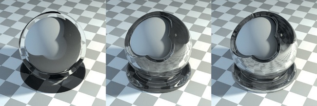
Glass BSDF. The Glass BSDF function transmits light as glass or any other transparent medium does. The index of refraction (IOR) determines how much the light is bent when it penetrates a surface. The higher the value, the more it is bent. Denser materials have higher IORs. For example, the IOR of glass is around 1.5, and the IOR of water is about 1.3. Diamond, a much denser material, has an IOR of around 2.4. The differences can be seen in Figure 12-8.
Translucent BSDF. This scatters light in all directions from the back of the object, resulting in a translucent appearance, like that of a thin paper or leaf, with light transmitted through the material.
Transparent BSDF. This allows light to penetrate a material without being refracted, as if there were nothing there. It’s useful when combined with alpha maps. (See Leaves for more on creating leaf materials.)
Velvet BSDF. This reflects light somewhat like the diffuse shader, but it reflects light more when viewed from oblique angles. The result is a velvety appearance.
Emission. This turns an object into a lamp that emits its own light.
Holdout. This creates a “hole” in an image that goes through to the background color with zero alpha transparency. It’s useful for compositing.
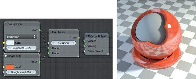
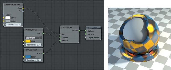
Mix Shader. This allows you to mix two shaders with the proportion of mixing determined by the factor input. The Mix nodes allow you to combine shaders in numerous combinations to create all sorts of materials. For example, you could create a plastic-like material by combining a Glossy BSDF and Diffuse BSDF shader, as shown in Figure 12-9.
Add Shader. This adds two shaders together. It’s less flexible than the Mix node because you can’t control the amount of mixing, but it works much the same way.
For more on these shaders and other Cycles documentation, visit http://wiki.Blender.org/.
Other Inputs in Cycles
Cycles allows you to use a wide variety of nodes that supply different data for use in your materials. You’ll find nodes to input image textures and procedural textures as well as nodes to supply geometric information, such as surface normals and the position of the surface in 3D or UV space (allowing you to map textures to a surface). Combining these nodes can prove a powerful tool, as we’ll see throughout the chapter.
Texture Nodes
The Texture nodes are particularly useful for creating materials, and they can supply a variety of procedural and image-based textures for use on your materials. I’ll use the image Texture nodes to apply the textures I created in Chapter 10 and Chapter 11.
The other nodes create procedural textures. For example, the noise texture creates multicolored clouds that are useful for adding random-looking detail to surfaces, and the waves texture creates repeating bands that can be distorted to look like wood grain. The checkerboard is a great texture for testing out material settings; for example, by connecting a checkerboard node to the Fac input of a Mix Shader node, you can use it to compare two shaders (see Figure 12-10). We’ll cover using textures with Cycles in more detail later in this chapter.
Nodes in Blender Internal
While I won’t cover them in detail, Blender Internal also supports node materials. Although the principles are the same, these work slightly differently from Cycles nodes. Instead of shaders, you can use other materials as inputs and combine them to make new materials. Figure 12-11 shows two materials combined to create a third.
Materials for the Bat Creature
Let’s look at how to create materials, beginning with the Bat Creature and Blender Internal. For this project, I needed materials for the skin, fur, eyes, and teeth.
Skin
I began with the creature’s skin. I added a new material to the Bat Creature object—that is, our final one with displacement, which I’ll use for rendering. (Remember there are two copies of the Bat Creature in the scene: one copy that I’ll use to render the body and another that I created in Chapter 9 to hold the hair.) To add a new material to the Bat Creature, I went to the Materials tab of the Properties editor and deleted any existing material slots (by clicking the – button at the top of the tab). Then, I clicked +New from the material selector drop-down menu. I could then start creating the material. The beginnings of the material are shown in Figure 12-12.
So far, this was just a simple material; I merely tweaked the diffuse color and the specular intensity and hardness. I also switched the specular shading to Blinn, which gave softer highlights. Next, I needed to start incorporating my textures and refining the material.
To incorporate the diffuse texture, I switched to the Textures tab of the Properties editor, selected the first texture slot, and clicked +New to add a new texture. Then I set the Texture Type to Image. This added an Image panel to the Texture tab where I could open my diffuse texture.
Mapping Coordinates
To apply the texture to the mesh properly, I needed to tell the material to use the UV coordinates that I created in Chapter 8.
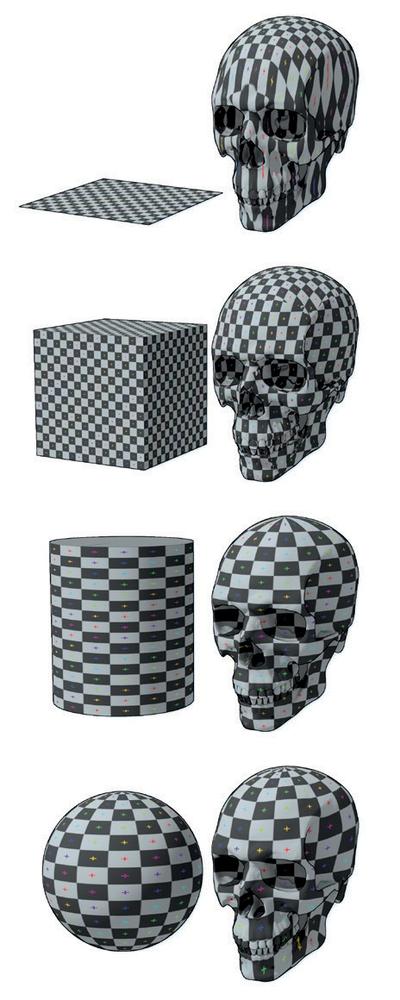
To do so, I could set the Coordinates option in the Mapping panel to UV. There are several other choices here, though, that are worth discussing. For example, the Generated option will create a procedural projection using the Projection setting below, which can be useful for applying seamless textures without having to unwrap an object. Generated coordinates project the surface of the object onto an imaginary shape—a plane, a cube, a sphere, or a cylinder—and use this projection to apply the texture. The result is shown in Figure 12-13.
We’ll use some of the other options, such as strand coordinates, later in this chapter. We’ve already seen normal coordinates in action, when applying MatCap images for use with GLSL shading.
Influence
The Influence panel of the Materials tab is where we set which properties of the material our texture will affect. The panel lists all the material properties that textures can be used to control, such as normals; hardness; alpha transparency; and diffuse, specular, and mirror colors and intensities. For our diffuse texture, we’ll stick with the default of Color, under the diffuse properties, which sets the diffuse color of the surface using the texture’s RGB values (see Figure 12-14). I set the Blend mode for this texture to Mix, meaning it will replace the default diffuse color specified in the Material settings.
You can also use only the black-and-white value of a texture and ignore its color information by checking the RGB to Intensity option. This lets you choose a specific color to multiply this value within the color picker below it, for use with properties that still need colors. The Negative option inverts the texture before applying it to the model. The Stencil option can be particularly useful for combining procedural textures because it makes the texture act as a mask for the texture slots below: White areas of the texture will allow subsequent textures to be applied, while black areas will show only textures higher up in the texture slot stack.
Further Textures
Now, I’ll continue to apply textures to my material. First, we’ll look at the specular and hardness textures that I created in Chapter 11. To add the specular texture to the material, I selected the next empty texture slot from the top of the Textures tab and clicked +New from the texture selector drop-down menu to create a new texture block. I set its type to Image. Then, I set the mapping to UV as before, but this time, under the Influence option, I set the texture to affect the specular color of the material. I set the Blend mode to Multiply so that the values from the texture were multiplied with the overall specular color of the material.
For the hardness texture, I set the texture to affect the material’s hardness, and I enabled the RGB to Intensity option to make sure Blender would treat the texture as a simple brightness value rather than as three color values. (RGB textures can fail when used with inputs that don’t require color information.) I set the Blend mode to Multiply.
Note that having a hardness value of 0 gives strange results, so either make sure the hardness texture contains no fully black areas, or set the influence of the texture to less than 1 to eliminate this issue.
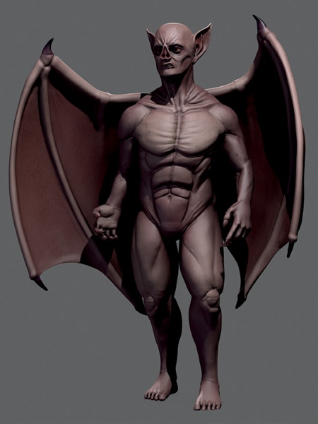
This completed adding textures to my material. The current result is shown in Figure 12-15.
Adding a Normal Map
Though I had finished adding textures to the material, you may remember that in Chapter 11, I also baked a normal map for the Bat Creature as a potential alternative to using displacement. At this stage, I could add the normal map in another image texture slot and set it to affect the Normals of the material in the Influence options. I also had to tell Blender that this is a tangent space normal map (not a bump map or an object space normal map), so in the Image Sampling panel of the Textures tab, I enabled the Normal Map option and made sure the Normal Map Space option just below was set to Tangent. The resulting material will use the textures to distort its normals when rendered, making it look more detailed even with subdivision and displacement mapping turned off.
As I was using displacement mapping, I didn’t need to use my normal map at all, but it’s a fair alternative if you want to keep render times low or if your computer is struggling with the poly count of the scene.
Subsurface Scattering
Subsurface scattering (SSS) is the effect of light bouncing around below the surface of a material, and it’s common in materials like skin, wax, and marble. It results in the edges of shadows looking somewhat blurred, as light diffuses out from fully lit areas to areas in shadow. As the light scatters, some of it is absorbed, with the remaining light usually taking on the color of the underlying substance. In the case of skin, the flesh and blood below the skin cause the scattered light to appear an orange-red color.
To replicate this effect in Blender Internal, we can enable subsurface scattering for a material. This effect approximates the scattering of light within an object by precomputing the lighting over its surface and then blurring the shadows. It also causes light to scatter through thin parts of the model. This produces a nice effect when combined with lighting the subject from the back (as I will light the Bat Creature in Chapter 13).
Enabling subsurface scattering in the Materials tab of the Properties editor gives you a lot of options to play with. The settings for subsurface scattering are as follows:
IOR. This is the index of refraction of the material. High IORs result in slightly softer boundaries between light and dark.
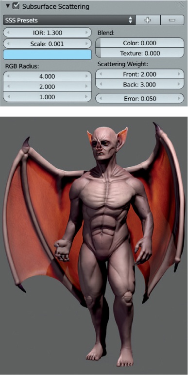
Scale. This is the most important setting, because it determines the scale of the scattering effect as a ratio between Blender’s units in the 3D Viewport and real-world scales. If you’ve built your scene to a scale of 1 Blender unit = 1m, then a value of 0.001 is “correct,” though you can set this to whatever value achieves the desired results (see Figure 12-16).
Scattering Color. This determines the color of light scattering. Its effect depends largely upon how you set the color blend (as discussed below). When the color blend is set high, it colors all of the scattered light with the color you choose, generally turning your whole mesh that color. When the color blend is set to 0, it has the opposite effect, causing the scattered light to take on the inverse color—that is, the color on the opposite side of the circle in the color picker (see Figure 12-17).
RGB Radius. In many materials, some colors of light scatter farther than others. For example, in pale skin, red light scatters farthest, green scatters about half as far as red light, and blue scatters about a quarter as far as red light. These settings let you define the relative scattering distances for red, blue, and green light.
Blend (Color/Texture). These settings determine how much the scattering color and diffuse texture spread out. I generally set both of these very low, if not to 0, because the results are more pleasing. High color blend values tend to cause the scattering color to wash out any other colors in the material (see Figure 12-17), and high texture blend values cause the texture to look blurry.
Scattering Weight (Front/Back). This adjusts the relative amount of scattering from the front and back of the model. Increasing the back scattering weight causes light to scatter through thin parts of the model more noticeably, which is often desirable. Setting the front value to 0 causes the material to scatter no light from the front of the surface, making it black for all but back scattered light, as shown in Figure 12-18. (This is sometimes useful in node material setups.)
Error. This value determines the quality of the SSS effect. Lower values give more accurate results but at the cost of longer render times. The default value is usually fine.
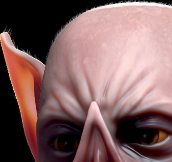
For the Bat Creature, I set the SSS settings as shown in Figure 12-19. I set the scale relative to the size of the creature, which I created at a 1m = 1 Blender unit scale, and chose teal for the scattering color, which together with a color blend set to 0 gave a nice orange scattering. I set the back scattering weight high to allow light to scatter through the wings. This completed the skin material for the Bat Creature.
Teeth, Nails, and Eyes
To create the materials for the teeth and nails, I started by duplicating the material I created for the skin, toning down the SSS effect, and increasing the overall specularity to make these areas shinier.
To duplicate a material, assign it to an object. Then, in the material selector drop-down menu, click the + icon to make a new material by duplicating the one currently assigned. You can then modify the duplicate leaving the original unchanged. This is useful when creating a material similar to one you have already made.
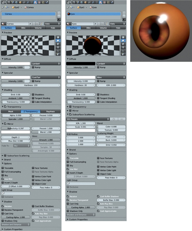
For the eyes, I created two new materials. Recall that when I modeled the eyes in Chapter 5, I created them as two separate parts: a cornea object that forms the outer surface of the eye and an inner part that would become the eyeball itself. Having unwrapped and textured the inner part, I set up a material similar to the skin material, with slightly less red subsurface scattering. I also turned specular reflections for this material off (by setting the specular intensity to 0), as the specular reflections for the eye will come from the cornea object. I applied the eye texture I painted in Chapter 11 as the diffuse texture for the material.
For the cornea, I needed a shiny, transparent material that wouldn’t cast a shadow on the inner eye object. To produce this, I created a new material assigned to this object. Then, I turned on transparency in the Material settings and set it to Z Transparency, with the alpha for the material set to 0. These settings make a material transparent, with the exception of any specular and mirror reflections, if they are present. I turned the specular and hardness of the material up quite high, and to prevent the material from casting shadows, I disabled Traceable in the Options panel and Cast Buffer shadows in the Shadows panel. The two materials for the eyes can be seen in Figure 12-20.
Fur
Materials for fur are a little more complex than regular materials and require a bit of knowledge about lighting and rendering. I’ll cover the material aspects here and some of the lighting aspects in Chapter 13.
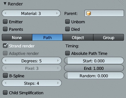
In Blender Internal, strand particles can be rendered either like any other material or using Blender’s Strand rendering option. Blender’s Strand rendering option offers a much faster way to render hair and fur, but it isn’t compatible with ray-traced shadows. Instead, it allows only for the rendering of shadows using spot lamps with buffered shadows.
To enable strand rendering, use the Render panel in the Particles tab of the Properties editor (see Figure 12-21). For the Bat Creature, I opted to use strand rendering. In Chapter 13, we’ll discuss creating an appropriate lighting setup for use with this setup.
Next, I specified the Strand options for the material. In the Strand panel of the Materials tab, you can specify how thick the strands will be and their shape, among other options:
Size (Root/Tip/Minimum). This determines the thickness of the particles at the root and tip of the hair. The Minimum setting specifies the minimum width of a strand in pixels that Blender will render.
Blender Units. By default, the thicknesses you specify using the Size setting are specified in pixels. This can be problematic if you have a lot of particles at different distances away from the camera, as they will be rendered with the same width in pixels, making the faraway ones look too thick. Turning on Blender Units lets you specify particle width in Blender units instead.
Tangent Shading. This option uses the strand’s tangent direction rather than its normal for shading, which generally gives better results.
Shape. This modifies the transition between the width of the root and the tip of the strand. The default value of 0 gives a linear transition. Negative values result in a spiky shape, while positive values make the strand look more rounded at the end.
Width Fade. This setting causes the strand to fade across its width, but only when strand rendering is enabled.
UV Map. This allows you to overwrite one of your UV coordinate sets to provide a UV map for the strands. In turn, this lets you UV map an image to all your strands for texturing, but it works only with strand rendering disabled.
Surface Diffuse. This setting causes the diffuse shading of the surface to blend with the strand shading over the specified distance.
Strand Coordinates
As mentioned above, we can texture strand materials by using the UV map override. A simpler option, however, is to use the strand coordinates for mapping when applying textures. While this only gives a one-dimensional coordinate along the length of the strand, this is usually enough for thin strands anyway.
For the Bat Creature’s fur, I first set up a simple material using the settings shown in Figure 12-22. Notice that I enabled Z Transparency and set the Alpha to about 0.7. For the Strand settings, I enabled Blender Units and then set the Root and Tip sizes to 0.00125 and 0.0001, respectively. (These values are small because the hairs need to be very thin, and their widths are now given in Blender units.) I also turned on Tangent Shading and set Width Fade to 1.0.
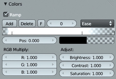
Next, in the Texture settings, I used Blender’s procedural blend texture to add a fade to the hair’s alpha along its length, making it become transparent toward the tip. I added a new texture to the material’s first texture slot and set its type to Blend. Then, I began adjusting the colors of the blend texture by first enabling the Ramp option in the Colors tab and then adjusting the colors that the procedural texture used. I clicked Add to create a couple more stops along the gradient and then set the colors to fade from transparent black to opaque white and back (see Figure 12-23). Finally, under Mapping, I set the texture’s coordinates to alpha, and under Influence, I set the texture to multiply with the material’s alpha and its specular intensity.
I did something similar for the hair color. I created a new blend texture in the next Texture slot, but this time I set up a blend from black to white (both alpha 1.0). Again, I mapped the texture to the strand coordinates and set it to multiply by a factor of 0.8 with the strand’s diffuse color, which made the base of the strands a little darker, thus faking a bit of shadowing.
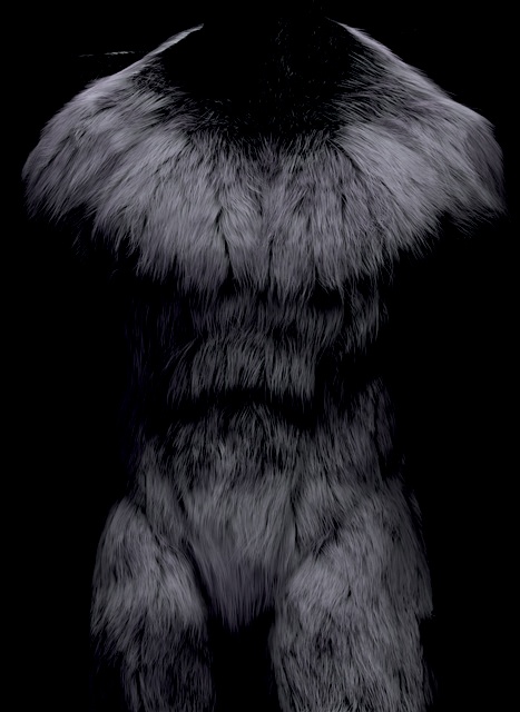
Next, I added a cloud texture, which I set to modify the material’s color—this time influencing the diffuse color with a factor of 0.8, with the Blend mode set to Multiply and its mapping set to UV. I turned the scale of the cloud texture down to the absolute minimum, essentially turning the texture into black-and-white noise and giving each hair a slightly different brightness. This completed the hair material, with the resulting hair seen in Figure 12-24.
Peach Fuzz
I set up a very similar material for the peach fuzz particle system. For this material, I decreased the size settings for the strands to make them thinner and reduced the overall alpha of the material to make the hair look wispier. The resulting material can be seen in Figure 12-25. It mainly shows up around the edges of the body, which is just what I wanted.
This completed my materials for the Bat Creature.
Materials for the Spider Bot
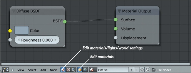
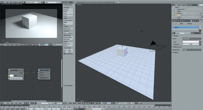
For the Spider Bot, I chose to use Blender’s Cycles renderer because it allowed me to create some nice shiny materials to complement the model. I began by creating a single material to apply to all the (textured) parts of the Spider Bot mesh. You can use the Material Utils Script to do this quickly: Simply enable it in Blender’s Add-Ons menu (User Preferences▸Add Ons) and use the shortcut Q to assign materials to all your selected objects at once. By default, when you create a new Cycles material for an object, Blender will assign a diffuse BSDF shader, like the one shown in Figure 12-26. The default material will be a plain matte white.
Editing Node Materials
To edit Cycles materials, use Blender’s Node editor, keeping it visible alongside the 3D Viewpoint with a render preview of the scene (a major advantage over Blender Internal that I’ll discuss shortly). To allow space for the Node editor as well as the preview, I split the default layout once by right-clicking on the bottom edge of the 3D Viewport and choosing Split Area. Then, I split the left-hand area in two, horizontally.
Once I split up the work area, I made one of the new areas into a Node editor and the other into a 3D Viewport, with its Display Method set to Rendered. In the Node editor header, I selected the materials icon in the left-hand group of icons and the cube icon in the right-hand group (see Figure 12-27) so that the Node editor would display the node tree for the current material. This gave me a workable layout for editing Cycles materials.
The Cycles Render Preview
When the Display method for a 3D Viewport is set to Rendered, Blender will continuously render and update a Cycles render of the current view in that viewport (as in Figure 12-26). This technique is a great way to get instant feedback on how the materials and lighting in your scene will look.
Note
While we haven’t covered lighting yet, it’s helpful at this stage to add some basic lights to the scene so that the rendered preview will reflect the final look. Jump to Chapter 13 for more on lighting, or simply add a couple of lights to the scene by pressing SHIFT-A in the 3D Viewport, choosing Lamps▸Point, and adding a point light. Adjust the brightness of the light using the Strength setting in the Object Data tab of the Properties editor. Add a couple of basic lights to the scene just to help work on materials, or create a more finished lighting setup.
Adding Textures
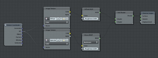
Next, I started combining further shaders into my material. I began by adding a Glossy BSDF shader (SHIFT-A▸Shaders▸Glossy BSDF) and using an Add Shader Node to blend the glossy and diffuse shaders by connecting both of the shader output sockets from the Shader nodes to the Add node and by connecting the Add node output socket to the Material Output node (see Figure 12-27).
Next, I started incorporating my textures, beginning with my diffuse map. I added an Image Texture node (SHIFT-A▸Textures▸Image Texture) and opened my diffuse map by clicking the folder icon in the node. I connected the color output of this node to the color input of my Diffuse Shader node.
I did the same for my specular color map, connecting it to the color input of the Specular Color node. By default, the mapping for these textures is the active UV coordinate set, so you don’t strictly need to define this manually. But because it can help to know what coordinates a texture uses, I added a Texture Coordinates node to the scene and connected its UV output to the vector (blue) input of my Image Texture nodes. Doing so tells these nodes to use the active UV map as the source of their texture coordinates. The node setup so far is shown in Figure 12-27.
Socket Types
Now that I have a reasonably complex node setup for the material, let’s talk about node sockets. Node sockets are the little colored circles that denote the inputs and outputs of a node and that allow nodes to be connected by clicking and dragging a connection from the output socket of one node to the input socket of another. Notice in Figure 12-27 that the sockets we used to connect nodes all have matching colors—green with green, yellow with yellow. The colors need to match because different output sockets pass different types of data and different input sockets expect different kinds of data. Some may require color information, some only a single value. Others may require vector information, like texture coordinates or normals.
Node sockets are color coded to clarify what a node expects as input and what it creates as output:
Blue sockets are for vector data. They can carry multiple values, such as UV coordinates (two dimensional) or position data (three dimensional).
Green sockets are for shaders. They carry all the information that determines how a material interacts with light.
Gray sockets are for value data. They carry a single numerical value.
Yellow sockets are for color data. They carry RGBA values (red, green, blue, and alpha).
Certain types of sockets can be mixed and matched. For example, value sockets can be used as the input for color sockets, and Blender will simply treat the value data as a black-and-white image. Color sockets can also be attached to value inputs, and Blender will use the overall brightness of the color as a value input. However, shader sockets are more complex and can only be connected to other shader sockets.
Roughness Map
In Chapter 11, I created a roughness map for the Spider Bot. In Cycles, I can connect this map to the roughness input for the Glossy BSDF node to control how blurry or sharp the reflections from the material should be. Dark areas will have sharp reflections, while light areas will have blurry ones (remember, this is the opposite of a hardness map).
To accomplish this, I added a new Image Texture node, loaded in the roughness map, and connected its output to the Glossy nodes roughness input. As a result, bright areas of the texture had blurrier highlights, and dark areas had sharp, glossy highlights.
I also set the color space of the Image Texture to Non-Color Data from the drop-down menu in the Image node to indicate that this node was not being used as a color image, ensuring that Blender wouldn’t perform any gamma correction on this node.
Adjusting Inputs
To get the most out of my textures without having to edit them in GIMP, I tweaked them using Blender’s nodes. For instance, to darken the diffuse colors a little and make the reflections from the glossy shader a little sharper, I added a Color Mix node, setting its type to Multiply, its factor to 0.5, and its second color input to black.
When this Color Mix node is dragged over the connection between an Image Texture node and a Shader node, Blender adds it to the chain automatically. (The connection will be highlighted, and the new node will be inserted when you drop it.) I did this for the connection between the diffuse map and the Diffuse BSDF shader to darken the texture slightly.
For the Glossy BSDF shader, in order to sharpen up the reflections, I needed to reduce the values of the input to the roughness shader. I accomplished this by adding a Math node between my roughness image Texture node and the roughness input of the glossy shader. I set the operation of the node to Multiply and set the second value of the node to 0.5. This halved the values from the roughness image before passing them to the Glossy Shader node so that the overall roughness of the input to the shader was halved, giving sharper, more glossy reflections.
For the shiny green areas of the mesh, I added some variance in color based on the angle of the surface to the camera. This gave the material a nice iridescent look. I accomplished this by adding a Geometry Input node (SHIFT-A▸Input▸Geometry) to provide the surface normal as an input and a Normal node to take the dot product of this input with the view direction. I then used this dot product output to modify the hue of my specular color map with a Hue Saturation Value node. By using the dot product output of the Normal node, I got a value (rather than a vector) that varied with the surface normal of the material. When this value was used to affect the hue input of the Hue Saturation Value node, the color of the material was subtly shifted as the surface of the material tilted away from the camera. You can see the node chain I used in Figure 12-28. It’s a somewhat complex setup, but seeing it laid out and testing it for yourself should help you make sense of it.
Other Materials
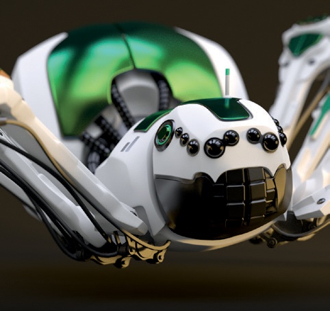
I still needed to make a couple of materials for the Spider Bot: a shiny material for the eyes (I used a simple glossy shader set to dark gray, with a slight roughness of 0.05) and a material for the wires (I combined a glossy shader and a diffuse shader with a Shader Mix node). You can see these materials in Figure 12-29 and the finished Spider Bot material in Figure 12-30.
Materials for the Jungle Temple
I used the Cycles renderer for the Jungle Temple scene as well. This scene needed a variety of materials: leaf materials for the foliage, generic materials for the rocks and soil, and a couple of unique materials for the objects I textured individually, such as the foreground stones and the statues.
Ground
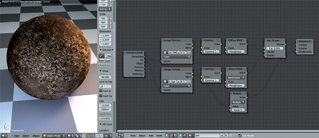
The ground material was probably the simplest to create. It’s simply a mix of a Diffuse and a Glossy BSDF shader, using my painted textures as inputs for the colors. Because I felt my original textures made the material look a little light, I used a Gamma node to darken them slightly without losing too much contrast (see Figure 12-31).
Stone Material
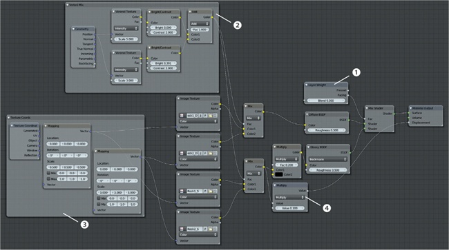
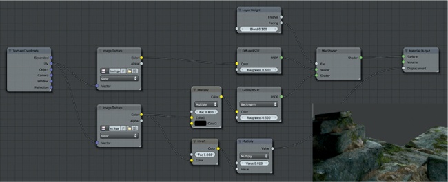
For my stone material, I wanted to combine the two different stone textures I made in Chapter 11, allowing each to show through in different areas, to give a bit of variation in the look of the material. To do so, I started by creating a basic shader that mixed a diffuse and glossy shader together using a Shader Mix node. I controlled the amount of mixing with a Layer Weight node, using its blend output. The Layer Weight node blends from 0 to 1 depending on the normals of a mesh: Surfaces facing the camera get low values, and ones facing away get high values (the exact values depend on the output used—facing or fresnel). Using the Facing output of this node to control the blending between the glossy and diffuse shaders produced some shiny highlights around the edges of objects with a more diffuse look when viewed straight on, as shown in section 1 of Figure 12-32.
To create a patchy distribution for the different stone textures, I combined a couple of Voronoi Texture nodes with different scales and then used these to control the mixing between the different textures for the rocks for both the specular and diffuse maps, as shown in Figure 12-32 2. I also used some Map nodes to scale up the texture mappings for my rock textures to make them match one another and fit the scale of the scene, which you can see in Figure 12-32 3.
Displacement
Cycles currently supports the use of a black-and-white input (or converting an RGB input to just a single value) to mimic the effect of small bumps in the surface of a material. This is often referred to as bump mapping in other render engines. Cycles does not yet support normal maps.
To add a bit more of a textured look to the surface of my rocks, I used the specular colors (the two mixed together) as the displacement input for the Material Output node, though I used a Multiply node to scale down their values to reduce the effect, as shown in Figure 12-32 4. The finished rock material is shown in Figure 12-33.
Statue
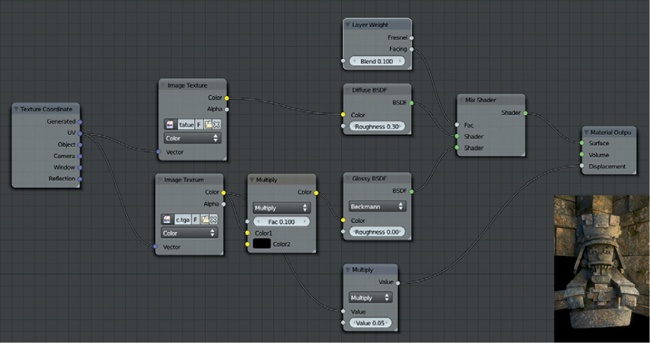
The statue material is basically just a copy of the generic stone material, except that it uses the textures I painted for the statue. To create it, I applied the stone material to the statue and then clicked the + icon in the material selector drop-down menu to make a new material using the current one. Next, I deleted (X) the extraneous nodes from the material in the Node editor and replaced them with my textures for the statue (see Figure 12-34).
Leaves
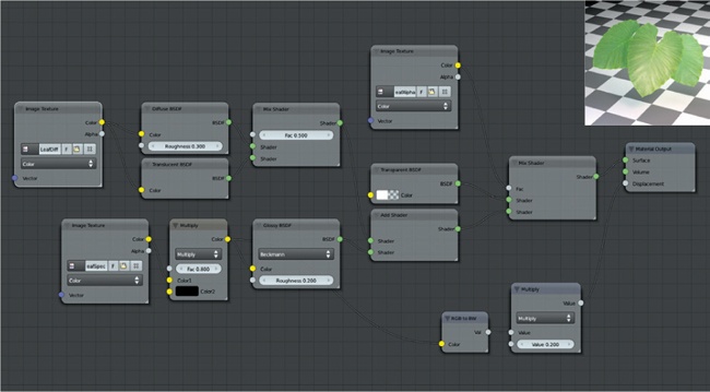
For the leaves, I wanted a translucent material so that leaves illuminated on one side would appear bright when viewed from the unlit side as well. To achieve this, I mixed a Translucent BSDF shader with a Diffuse BSDF shader and mixed in specular highlights on top to make the leaves shiny. The leaf meshes had to be transparent in order to make the areas of the mesh that weren’t part of the leaves invisible. I accomplished this by mixing the result of all the nodes so far with a Transparent BSDF shader, using the alpha map from Chapter 11 to control the mixing (see Figure 12-35).
Foreground Rocks and Soil
In Chapter 11, I created a hand-painted texture for the foreground objects from the camera’s perspective. To use this, I needed to create a unique material for these objects. I began by duplicating the material I created for the statue and then replacing its texture inputs with the ones I created for the foreground objects.
To map the textures to the models correctly, I snapped the 3D Viewport to the camera view (NUMPAD 0) and UV unwrapped the foreground objects using the Unwrap▸Project from View operator for each object to which the material was applied. This projected the objects’ UV coordinates to match the camera’s perspective and so allowed me to use the UV coordinates as the texture coordinates. The material nodes for this material can be seen in Figure 12-36.
Puddles
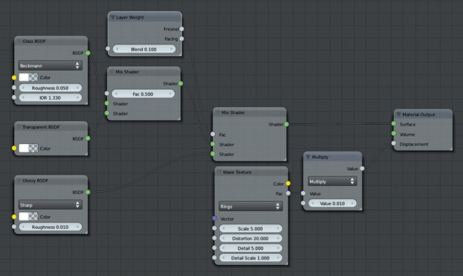
For the puddles, I needed a water material that would let some light penetrate the surface and show some reflections. The glass material alone would do the job (using an IOR value of 1.33, equal to that of water), but to get a bit more control over how much light would penetrate the surface and the strength of the reflections, I blended Transparent, Glass, and Glossy BSDF shaders. I mixed in the glossy shader using a Layer Weight node connected to the Mix node to get a bit of extra reflection at low viewing angles.
To produce ripples in the surface of the water, I created a Waves Texture node (SHIFT-A▸Texture▸Wave Texture) and connected it to the displacement socket on the Material Output node to create some distortion in the water’s surface. By default, the Waves node gives straight, repeating waves, but by setting the wave type to Rings and increasing the distortion value, you can get some nice ripples (see Figure 12-37).
General Tips for Creating Materials
Here are some general principles to keep in mind when creating materials in your projects. Chiefly, they involve paying attention to the real-world equivalents of the materials you are trying to replicate and constructing your material accordingly:
Keep reflection amounts sane. Make sure that the total amount of light your object is reflecting is sensible. When using the Add node to combine shaders in Cycles, it’s possible to create a material that reflects more light than it would realistically receive in the first place by adding too many shaders together. Similarly, in Blender Internal, keep in mind that the diffuse and specular reflection amounts (plus the light absorbed by the object) should roughly add up to 1—for example, a diffuse intensity of 0.6 and a specular intensity of 0.3, leaving some absorbed light to spare. Otherwise, your material will look unrealistically bright next to other materials.
There are no perfect materials. No material reflects 100 percent of all light, and no material absorbs 100 percent either. Try not to make any materials that are completely dark or completely white (unless you are doing so for a good reason).
Use saturation in moderation. The color of a material is rarely 100 percent saturated, even for brightly colored materials like plastics. Most everyday colors are less than 85 percent saturated, so keep the colors of your materials in a sensible range to make them believable.
Keep it simple. Try to avoid making complex materials to ensure shorter render times. For example, in Blender Internal, try to use ray-traced reflections only when really needed.
Supplement materials with procedural textures. Blender’s built-in procedural textures are a great way to supplement materials by using them as bump maps or to blend other textures. Doing so can add a lot of variation to your materials while preventing you from having to laboriously hand-paint textures.
In Review
In this chapter, we started with a look at Blender’s options for creating materials, both for the Blender Internal renderer and Cycles. Because these two render engines require different approaches when creating materials, we explored their different options and requirements. Then we moved on to creating materials for the three projects. For the Bat Creature, I created Blender Internal–compatible materials for the body, fur, eyes, nails, and teeth. For the body, I created a material with subsurface scattering to mimic realistic skin, and for the fur, I covered the different options for fur materials and rendering. I used Blender’s strand shader to render the fur and examined ways to apply textures to fur.
For the Spider Bot and the Jungle Temple scene, I created materials for rendering with Cycles, using Blender’s Node editor to create a range of different materials by combining Shader nodes and using textures to supply their inputs.
The projects are now ready to be lit and rendered. In Chapter 13, you’ll learn about different lighting setups and how to use lighting in both Blender Internal and Cycles.
