Chapter 8. How High Did It Go?
After watching a rocket roar into the sky, seeing the smoke trail, and watching the rocket descend gracefully under a parachute, the first thing most people want to know about the flight is how high the rocket went. The second thing they want to know is how fast it went. We’ll investigate several methods to find out how high the rocket went in this chapter, and one method to find out how fast it went.
There are basically two practical ways to track the altitude of a model rocket. The first is to track the rocket visually, measuring the angle of the rocket from the launcher and using trigonometry to find the altitude. This is the method NAR uses most often for official tracking for contests and records for low-power rockets. The second method is to put an altimeter in the rocket. This finds the rocket’s altitude using a tiny barometer and accelerometer. Using an altimeter is the most accurate way to find the altitude of the rocket, and it’s also the favored way to track the altitude for high-powered rockets, which often go out of sight.
The Single-Axis Tracker
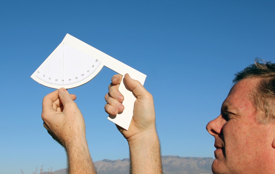
Let’s start with a single-axis altitude tracker—essentially, and sometimes literally, a protractor to measure an angle. This is a very simplified form of the kind of tracker used by NAR for contests. Keep in mind that while this tracker is great for giving a reasonable idea of the altitude of a rocket flight, it is not adequate for NAR-sanctioned contests. We’ll show a more sophisticated tracker, one that satisfies all of the NAR requirements, later in the chapter. Still, this first tracker is cheap, easy to build and operate, and reasonably accurate.
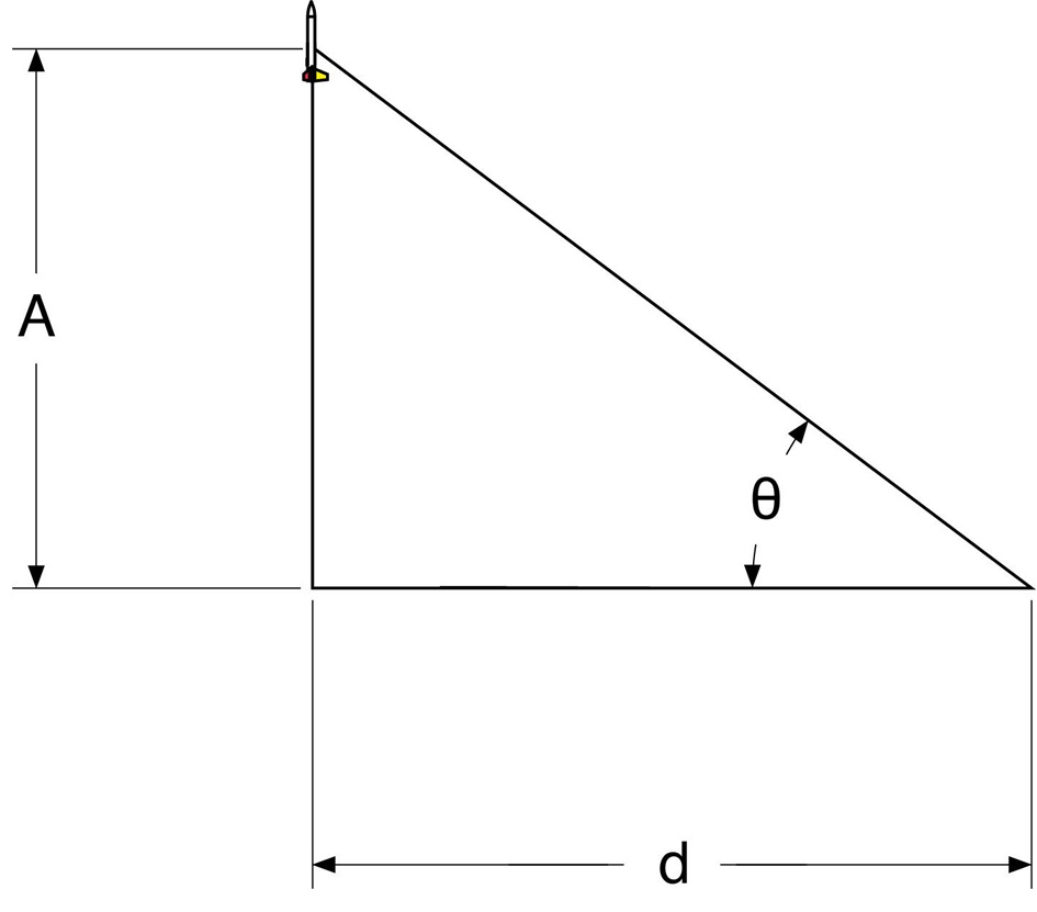
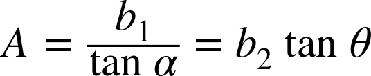
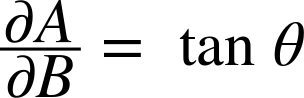
The idea is very simple, and very familiar to anyone who has taken a trigonometry class. If you know the distance from the launch pad to the tracker, and you know the angle between the ground and the rocket’s highest point, you can find the altitude of the rocket. We do make the simplifying assumption that the rocket went straight up. The altitude A is:

where d is the distance between the tracker and the launcher, and θ is the angle between the ground and the rocket.
The equation is pretty easy to use even if you don’t know much about trigonometry. The tangent function, abbreviated as tan, is available on most calculators. Table 8-1, later in the chapter, also shows the altitudes for various angles.
Building a Single-Axis Tracker
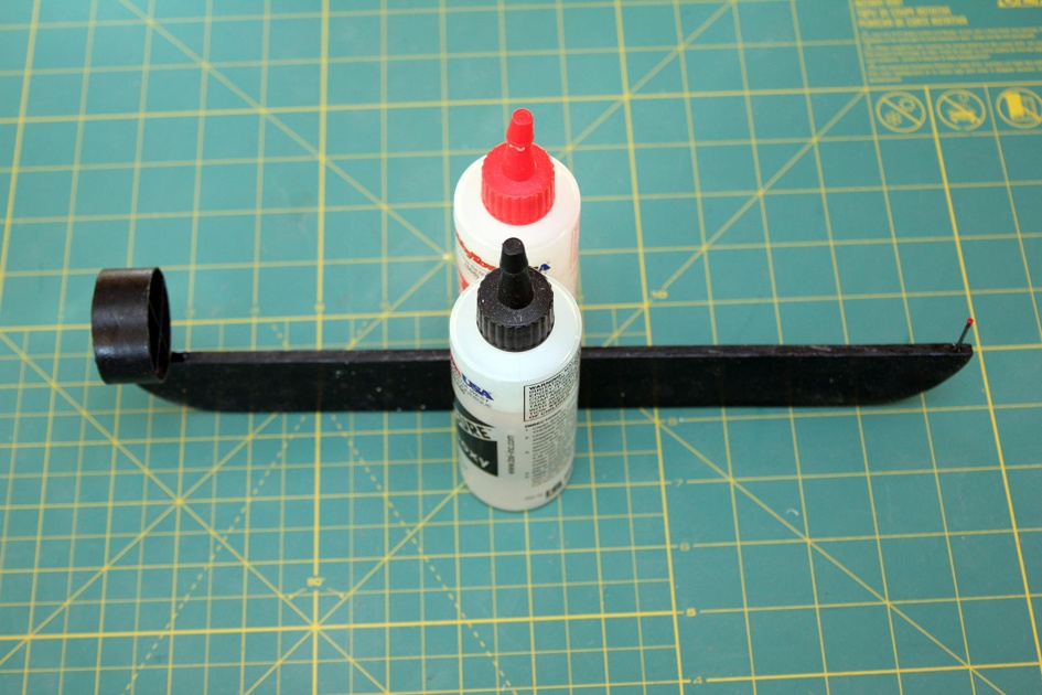
It is extremely easy to build a single-axis tracker. All you need is a protractor, a string, and a weight. The protractor should be as large as possible. Figure 8-2 shows one you can copy and paste onto foam core, cardboard, tin, or plywood. You can get a full-size template for the protractor and tracker at the author’s website.

Thread the string through the marked hole at the center of the protractor and tie the weight to the other end. The weight can be a fishing weight like the one shown, a ball of clay, or any other convenient dense material. Make sure the string is long enough to extend past the edge of the protractor. Tie a knot or use tape or glue to fasten one end of the string at the center of the semicircle, and fasten the other end securely to the weight.
The tracker is used to measure the angle between the launcher and the apogee of the rocket. Sighting along the top of the tracker to the launcher should give an angle of 0°. If not, the tracking position is uphill or downhill from the launcher. The best thing to do in that case is move. If moving isn’t practical, and the difference is small, adjust the final angle by subtracting the angle to the launcher from the angle to the rocket’s apogee.
When tracking the rocket, sight along the top of the protractor and follow the rocket to its highest altitude. Once there, clamp the string in place with your thumb so you can turn the tracker to read the angle without changing the angle.
A nice alternative to the homemade tracker is the tracker from Estes Industries shown in Figure 8-4. It uses a clever trigger mechanism to lock the measurement in place, and has great sights for accurate tracking.

Math Behind Single-Axis Trackers
The math in the first part of this section is appropriate for anyone who has had a trigonometry course, and can be followed by anyone who is adventurous and has had algebra. There is an error analysis section later that uses calculus. You can skip all of this and just use Table 8-1 to look up the altitude, but even if you don’t dig into the math, there are some interesting facts about where tracking error comes from that make it worth skimming this section.
The math used to find the altitude of the rocket relies on the definition of the tangent of an angle. The definition states that the tangent of an angle is the length of the opposite side of the triangle over the length of the adjacent side, provided the angle between the two sides is 90°.
From there, it’s a simple rearrangement to get the formula for the altitude of the rocket:

where A is the altitude, B is the length of the baseline, which is the distance from the launch pad to the tracker, and θ is the angle measured by the tracker.

Plugging in the data and solving the equation will give you a number, but how accurate is that number as a representation of the rocket’s altitude? Error analysis is both a well-known area of science and engineering, and a frequently ignored one. Look at it this way: if I tell you my rocket flew to 500 feet on an A motor, you might doubt my calculations. After all, the predicted altitude for Juno on an A motor is about 350 feet. Now, if I tell you I tracked my Juno to 500 feet plus or minus 100 feet, you’ll have more confidence that I didn’t mess up, simply because you understand I’m telling you the error was large. You might reasonably ask why I don’t work to get a lower error. That’s where understanding the math behind error analysis helps. It will show you, very clearly, which part of the measurement has the biggest effect on the error in the altitude for the rocket.
Let’s start by looking at what we mean when we give an error on a number. When I say the altitude is 500 feet plus or minus 100 feet, that’s usually written as 500 ±100 feet. The 100 is one standard deviation. A standard deviation describes the way many random samples fall about the middle of the data. In this case, it’s telling us that our attempts to measure something are likely to average to the correct value, and we’re more likely to be close to the correct value than really far away from it. Saying the standard deviation is 100 feet says there is a 68.2% chance the actual altitude was in the range of 400 feet to 600 feet, and a 95.4% chance it was in the range of 300 feet to 700 feet.
Table 8-1, later in the chapter, lists the error for various altitudes. Maybe that’s good enough for you. If so, feel free to skip the rest of this section. If you want to dig into the math, though, get ready for a little calculus.
The first thing we need to do is look at the equation and decide where error can creep in. It’s pretty clear we could be off a bit measuring the length of the baseline. Of course, we may not measure the angle accurately, either. These are measurement errors. One way to figure out the error is to make the same measurement multiple times and calculate the standard deviation. Another is to estimate the error. That’s what is done later for Table 8-1. We assume our measurement for the baseline is within 2%, and the angle is ±2°.
Can you do better than that? Maybe. Measure the angle to the top of a fixed object, like a flagpole, 10 or 20 times and find the standard deviation to see. Be sure to do it quickly, since a rocket will not give you time for a careful measurement. One way to do that would be to start off pointed away from the flagpole, then turn and take the measurement right away. Do the same for measuring a 500-foot baseline from the flagpole. Make a chalk mark each time to measure the distance and see how close they are. Yes, it’s painstaking. Welcome to engineering. If you want to get a better answer, it often takes more work.
There are two other sources of error that aren’t as obvious. They both have to do with the assumption that the angle between the baseline and the rocket at apogee is 90°. There are two reasons that might be off. The first is that the tracker might be uphill or downhill from the launch pad. Try measuring the angle to the launch pad itself. It should be 0°. If not, you’re uphill or downhill. For our calculations, we’ll assume you are approximately level with the launcher, and use 2° for this error.
The other source of error shows the real problem with a single-axis tracker. The rocket might arc toward the tracker, making the measured altitude much higher than the actual altitude, or it might arc away from the tracker, making the altitude appear too low. The cause of the rocket’s arc is usually the wind, so we can reduce this error by placing the tracker 90° from the direction of the wind. However, even if we do this, the error never goes away completely. Table 8-1 assumes the rocket is within 10° of the vertical.

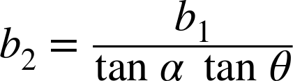
Now we can go back to our original equation and figure out how much these errors contribute to the overall error in altitude. First we have to make a change in the equation, though. Since the angle of the rocket might not be exactly 90° from the baseline, we need a new equation that includes the second angle.
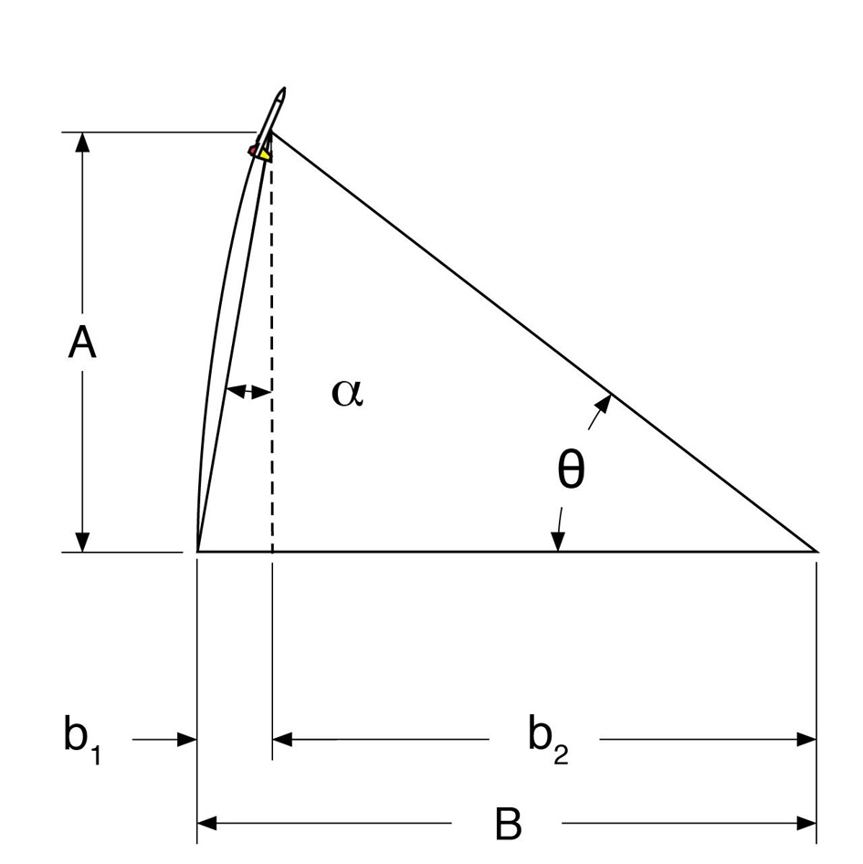
We need to develop an altitude equation that assumes α is not zero. A little algebra will do the trick. Start with the fact that the distance from the point under the rocket to the launcher and to the tracker is equal to the measured baseline:
We can use the definition of the tangent to find the relationship between the short baselines, the angles, and the altitude:


Solving for A gives us a relation between the angles and small baselines:
We need the value for b2 so we can find the actual altitude, so we need to solve this equation for b2:

Using the fact that

and doing a bit of rearranging, we end up with:

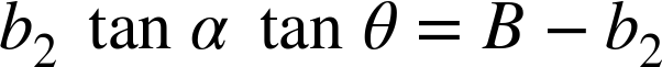


As a quick sanity check, if the rocket really does fly straight up, α is 0, so tan α is 0, and the altitude equation reduces to the original one we had before we started the error analysis.
With an altitude equation that has all of the sources of error included, it’s time to figure out the relative contributions of the errors. This involves a bit of calculus, since we will need to take some derivatives. If calculus is not something you’ve had a chance to master yet, skim over this section and check out the results.
Assuming the errors are relatively small compared to the measured values, we can get the square of the overall error by adding the square of the contribution of each individual error, multiplied by the square of the derivative of the equation with respect to the variable whose error we’re looking at.
Huh?
Let’s try it with math. It’s so much clearer that way. The error in the altitude, indicated as σA, is:

The fractions are partial derivatives. They indicate we should take the derivative. The partial derivatives are:


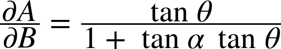
This simplifies a lot because α is supposed to be 0°. Making that substitution, the partial derivatives become:


This gives a final equation for the error in altitude of:

Let’s try an example to see how this would work. For our example, we will assume we are tracking a rocket we expect to reach an altitude of about 350 feet, so we’ll use a 300-foot baseline. That’s the value for B. Assuming a 2% measurement error, that gives B as 300±6 feet.
Let’s say the tracker returned an angle of 50°. This means θ is 50±2°.
The angle between the baseline and the line from the launcher to the rocket should be 0°, since we hope the rocket goes straight up. We’re allowing for a 10° error, to account for the arcing path of the rocket and the possibility that the tracker might be a bit uphill or downhill from the launcher. The means α is 0±10°.
The calculated altitude in feet is:


While most calculators are quite happy to use degrees or radians, the error in an angle needs to be in radians for the math to work. That means the error in each angle must be multiplied by π/180. The error is:


So the altitude is 358±79 feet. The error tells us we have an approximation of the altitude, but it’s only good to about 20% or so. The error analysis tells us more, though. It tells us that we need to work on making sure the rocket is vertical to get a good altitude measurement with a single-axis tracker, since the overwhelming majority of the error comes from the error in the angle between the baseline and the line from the rocket to the launcher. Knowing the error is useful. Knowing where the error comes from justifies the work of going through the math, because it tells us how to reduce the error.
Using a Single-Axis Tracker
Tracking the altitude of a rocket with a single-axis tracker is pretty easy. The first step is to lay out the baseline. This is usually done using a tape measure. The location for the tracker should be perpendicular to the wind direction to minimize the error in the launch angle. The sun should be behind the tracker so it doesn’t get in the eyes of the person doing the tracking. The length of the baseline should be roughly the same as the expected altitude of the rocket. The tracker should also be at the same elevation as the launcher—it should not be uphill or downhill from the launcher.

Official altitude measurements at NAR-sanctioned contests are done in meters, so the baseline is laid out in meters, too. Those of us in the US usually have better access to tape measures that measure feet, though, so it’s common to see measurements in feet for less official results. Either will work just fine.
You might not have a tape measure long enough to measure the baseline. If not, measure the distance from the launcher to the end of the tape measure, then measure the distance from that point to the end of the tape measure, and so on until you get the desired total distance. Be sure to measure in a straight line by sighting from your endpoint to the person standing at the last measured location and on to the launcher.

With the baseline measured, track the rocket to either its highest altitude or the ejection charge. It is usually easier to see the ejection charge than the rocket, particularly at higher altitudes, so the ejection charge is usually the better choice. Let the string and weight hang free as you track the rocket. Once you see the ejection charge, or when the rocket reaches apogee, clamp your thumb onto the string. Keeping your thumb on the string, bring the tracker down and read the angle. From there, you can either find the altitude using trigonometry, or look it up in the table in the next section.
Altitude Tables for Single-Axis Trackers
Table 8-1 shows the altitude of a rocket for various angles and baselines. Let’s see how it is used.
Find the baseline length along the top row of Table 8-1. Scan down to find the row showing the angle you measured with the altimeter. The table shows the altitude and standard deviation in the error for the altitude. The error calculation assumes the following measurement errors:
- Angle between the apogee and true vertical from the launcher: ±10°
- Baseline length: ±2% of the measured length
- Tracker angle: ±2°
The table works for either meters or feet. If the baseline is measured in feet, the altitude is in feet; if the baseline is measured in meters, so is the altitude.
| 100 | 200 | 250 | 300 | 400 | 500 | 1000 | |
1 | 2±3 | 3±7 | 4±9 | 5±10 | 7±14 | 9±17 | 17±35 |
2 | 3±3 | 7±7 | 9±9 | 10±10 | 14±14 | 17±17 | 35±35 |
3 | 5±4 | 10±7 | 13±9 | 16±11 | 21±14 | 26±18 | 52±35 |
4 | 7±4 | 14±7 | 17±9 | 21±11 | 28±14 | 35±18 | 70±35 |
5 | 9±4 | 17±7 | 22±9 | 26±11 | 35±14 | 44±18 | 87±35 |
6 | 11±4 | 21±7 | 26±9 | 32±11 | 42±14 | 53±18 | 105±35 |
7 | 12±4 | 25±7 | 31±9 | 37±11 | 49±14 | 61±18 | 123±36 |
8 | 14±4 | 28±7 | 35±9 | 42±11 | 56±14 | 70±18 | 141±36 |
9 | 16±4 | 32±7 | 40±9 | 48±11 | 63±14 | 79±18 | 158±36 |
10 | 18±4 | 35±7 | 44±9 | 53±11 | 71±15 | 88±18 | 176±37 |
11 | 19±4 | 39±7 | 49±9 | 58±11 | 78±15 | 97±19 | 194±37 |
12 | 21±4 | 43±8 | 53±9 | 64±11 | 85±15 | 106±19 | 213±38 |
13 | 23±4 | 46±8 | 58±10 | 69±11 | 92±15 | 115±19 | 231±38 |
14 | 25±4 | 50±8 | 62±10 | 75±12 | 100±16 | 125±19 | 249±39 |
15 | 27±4 | 54±8 | 67±10 | 80±12 | 107±16 | 134±20 | 268±40 |
16 | 29±4 | 57±8 | 72±10 | 86±12 | 115±16 | 143±20 | 287±41 |
17 | 31±4 | 61±8 | 76±10 | 92±13 | 122±17 | 153±21 | 306±42 |
18 | 32±4 | 65±9 | 81±11 | 97±13 | 130±17 | 162±22 | 325±43 |
19 | 34±4 | 69±9 | 86±11 | 103±13 | 138±18 | 172±22 | 344±45 |
20 | 36±5 | 73±9 | 91±12 | 109±14 | 146±19 | 182±23 | 364±46 |
21 | 38±5 | 77±10 | 96±12 | 115±14 | 154±19 | 192±24 | 384±48 |
22 | 40±5 | 81±10 | 101±13 | 121±15 | 162±20 | 202±25 | 404±50 |
23 | 42±5 | 85±11 | 106±13 | 127±16 | 170±21 | 212±26 | 424±53 |
24 | 45±6 | 89±11 | 111±14 | 134±17 | 178±22 | 223±28 | 445±55 |
25 | 47±6 | 93±12 | 117±14 | 140±17 | 187±23 | 233±29 | 466±58 |
26 | 49±6 | 98±12 | 122±15 | 146±18 | 195±24 | 244±30 | 488±61 |
27 | 51±6 | 102±13 | 127±16 | 153±19 | 204±26 | 255±32 | 510±64 |
28 | 53±7 | 106±13 | 133±17 | 160±20 | 213±27 | 266±34 | 532±67 |
29 | 55±7 | 111±14 | 139±18 | 166±21 | 222±29 | 277±36 | 554±71 |
30 | 58±8 | 115±15 | 144±19 | 173±23 | 231±30 | 289±38 | 577±75 |
31 | 60±8 | 120±16 | 150±20 | 180±24 | 240±32 | 300±40 | 601±80 |
32 | 62±8 | 125±17 | 156±21 | 187±25 | 250±34 | 312±42 | 625±85 |
33 | 65±9 | 130±18 | 162±22 | 195±27 | 260±36 | 325±45 | 649±90 |
34 | 67±10 | 135±19 | 169±24 | 202±29 | 270±38 | 337±48 | 675±95 |
35 | 70±10 | 140±20 | 175±25 | 210±30 | 280±40 | 350±51 | 700±101 |
36 | 73±11 | 145±21 | 182±27 | 218±32 | 291±43 | 363±54 | 727±107 |
37 | 75±11 | 151±23 | 188±29 | 226±34 | 301±46 | 377±57 | 754±114 |
38 | 78±12 | 156±24 | 195±30 | 234±36 | 313±49 | 391±61 | 781±121 |
39 | 81±13 | 162±26 | 202±32 | 243±39 | 324±52 | 405±65 | 810±129 |
40 | 84±14 | 168±28 | 210±34 | 252±41 | 336±55 | 420±69 | 839±138 |
41 | 87±15 | 174±29 | 217±37 | 261±44 | 348±59 | 435±73 | 869±146 |
42 | 90±16 | 180±31 | 225±39 | 270±47 | 360±62 | 450±78 | 900±156 |
43 | 93±17 | 187±33 | 233±42 | 280±50 | 373±67 | 466±83 | 933±166 |
44 | 97±18 | 193±35 | 241±44 | 290±53 | 386±71 | 483±89 | 966±177 |
45 | 100±19 | 200±38 | 250±47 | 300±57 | 400±76 | 500±95 | 1000±189 |
46 | 104±20 | 207±40 | 259±50 | 311±61 | 414±81 | 518±101 | 1036±202 |
47 | 107±22 | 214±43 | 268±54 | 322±65 | 429±86 | 536±108 | 1072±215 |
48 | 111±23 | 222±46 | 278±58 | 333±69 | 444±92 | 555±115 | 1111±230 |
49 | 115±25 | 230±49 | 288±61 | 345±74 | 460±98 | 575±123 | 1150±246 |
50 | 119±26 | 238±53 | 298±66 | 358±79 | 477±105 | 596±131 | 1192±263 |
51 | 123±28 | 247±56 | 309±70 | 370±84 | 494±113 | 617±141 | 1235±281 |
52 | 128±30 | 256±60 | 320±75 | 384±90 | 512±121 | 640±151 | 1280±301 |
53 | 133±32 | 265±65 | 332±81 | 398±97 | 531±129 | 664±162 | 1327±323 |
54 | 138±35 | 275±69 | 344±87 | 413±104 | 551±139 | 688±173 | 1376±347 |
55 | 143±37 | 286±75 | 357±93 | 428±112 | 571±149 | 714±186 | 1428±373 |
56 | 148±40 | 297±80 | 371±100 | 445±120 | 593±160 | 741±200 | 1483±401 |
57 | 154±43 | 308±86 | 385±108 | 462±129 | 616±173 | 770±216 | 1540±431 |
58 | 160±47 | 320±93 | 400±116 | 480±140 | 640±186 | 800±233 | 1600±465 |
59 | 166±50 | 333±100 | 416±126 | 499±151 | 666±201 | 832±251 | 1664±502 |
60 | 173±54 | 346±109 | 433±136 | 520±163 | 693±217 | 866±272 | 1732±543 |
61 | 180±59 | 361±118 | 451±147 | 541±176 | 722±235 | 902±294 | 1804±588 |
62 | 188±64 | 376±128 | 470±160 | 564±192 | 752±255 | 940±319 | 1881±638 |
63 | 196±69 | 393±139 | 491±174 | 589±208 | 785±278 | 981±347 | 1963±694 |
64 | 205±76 | 410±151 | 513±189 | 615±227 | 820±303 | 1025±378 | 2050±757 |
65 | 214±83 | 429±165 | 536±207 | 643±248 | 858±331 | 1072±414 | 2145±827 |
66 | 225±91 | 449±181 | 562±227 | 674±272 | 898±363 | 1123±453 | 2246±907 |
67 | 236±100 | 471±199 | 589±249 | 707±299 | 942±399 | 1178±498 | 2356±996 |
68 | 248±110 | 495±220 | 619±275 | 743±330 | 990±440 | 1238±549 | 2475±1099 |
69 | 261±122 | 521±243 | 651±304 | 782±365 | 1042±487 | 1303±608 | 2605±1216 |
70 | 275±135 | 549±270 | 687±338 | 824±406 | 1099±541 | 1374±676 | 2747±1352 |
71 | 290±151 | 581±302 | 726±377 | 871±453 | 1162±604 | 1452±755 | 2904±1510 |
72 | 308±169 | 616±339 | 769±424 | 923±508 | 1231±678 | 1539±847 | 3078±1694 |
73 | 327±191 | 654±382 | 818±478 | 981±574 | 1308±765 | 1635±956 | 3271±1912 |
74 | 349±217 | 697±435 | 872±543 | 1046±652 | 1395±869 | 1744±1086 | 3487±2173 |
75 | 373±249 | 746±497 | 933±622 | 1120±746 | 1493±995 | 1866±1244 | 3732±2487 |
76 | 401±287 | 802±574 | 1003±718 | 1203±861 | 1604±1149 | 2005±1436 | 4011±2871 |
77 | 433±335 | 866±670 | 1083±837 | 1299±1004 | 1733±1339 | 2166±1674 | 4331±3348 |
78 | 470±395 | 941±790 | 1176±987 | 1411±1184 | 1882±1579 | 2352±1974 | 4705±3948 |
79 | 514±472 | 1029±944 | 1286±1180 | 1543±1416 | 2058±1888 | 2572±2359 | 5145±4719 |
80 | 567±573 | 1134±1147 | 1418±1433 | 1701±1720 | 2269±2293 | 2836±2866 | 5671±5733 |
81 | 631±710 | 1263±1421 | 1578±1776 | 1894±2131 | 2526±2841 | 3157±3552 | 6314±7103 |
82 | 712±902 | 1423±1804 | 1779±2255 | 2135±2706 | 2846±3608 | 3558±4510 | 7115±9019 |
83 | 814±1181 | 1629±2363 | 2036±2954 | 2443±3544 | 3258±4726 | 4072±5907 | 8144±11814 |
84 | 951±1612 | 1903±3224 | 2379±4030 | 2854±4836 | 3806±6448 | 4757±8060 | 9514±16120 |
85 | 1143±2326 | 2286±4652 | 2858±5815 | 3429±6978 | 4572±9305 | 5715±11631 | 11430±23262 |
86 | 1430±3641 | 2860±7282 | 3575±9102 | 4290±10923 | 5720±14563 | 7150±18204 | 14301±36408 |
87 | 1908±6481 | 3816±12962 | 4770±16203 | 5724±19444 | 7632±25925 | 9541±32406 | 19081±64812 |
88 | 2864±14597 | 5727±29193 | 7159±36491 | 8591±43790 | 11455±58386 | 14318±72983 | 28636±145966 |
89 | 5729±58420 | 11458±116839 | 14323±146049 | 17187±175259 | 22916±233678 | 28645±292098 | 57290±584195 |
Dual-Axis Tracking
If you worked through the error analysis section for the single-axis tracker earlier in the chapter, you saw that the biggest problem with getting an accurate reading from a single-axis tracker is that the rocket might not go straight up. We can eliminate that source of error using a theodolite. A theodolite measures two angles, one from the horizon to the apogee of the rocket, as before, and a second from another theodolite to a point under the rocket at apogee. The angle from the horizon to the rocket is called the elevation angle, while the angle from the rocket to the other theodolite is the azimuth angle. Instead of locating the rocket somewhere along a line and assuming the rocket is right above the launcher, the dual-axis tracking system figures out the position of the rocket in three dimensions. If you wanted to, you could even find how far the rocket is from the launcher when it hits apogee.
The biggest problem with dual-axis trackers is that they are hard to come by. Dual-axis tracking also involves more people. Doing it well requires at least six people, and doing it at all takes at least three. The calculations are more difficult, too, so you can’t just plug an angle and distance into a simple formula, or look up the answer in a table. While we’ll walk through the math, in practical use you’ll need to use a short computer program to find the altitude of your rocket. Of course, I’ll give you that program.
Building a Theodolite
The theodolite we will build is a simple yet fairly accurate way to track the altitude of a rocket. It meets all of the requirements from the NAR Pink Book for use in contests. It is designed to mount on a standard camera tripod. Camera tripods can be very cheap or very expensive, but even the cheapest camera tripod is likely to be more stable and far more portable than a tripod you build from scratch.
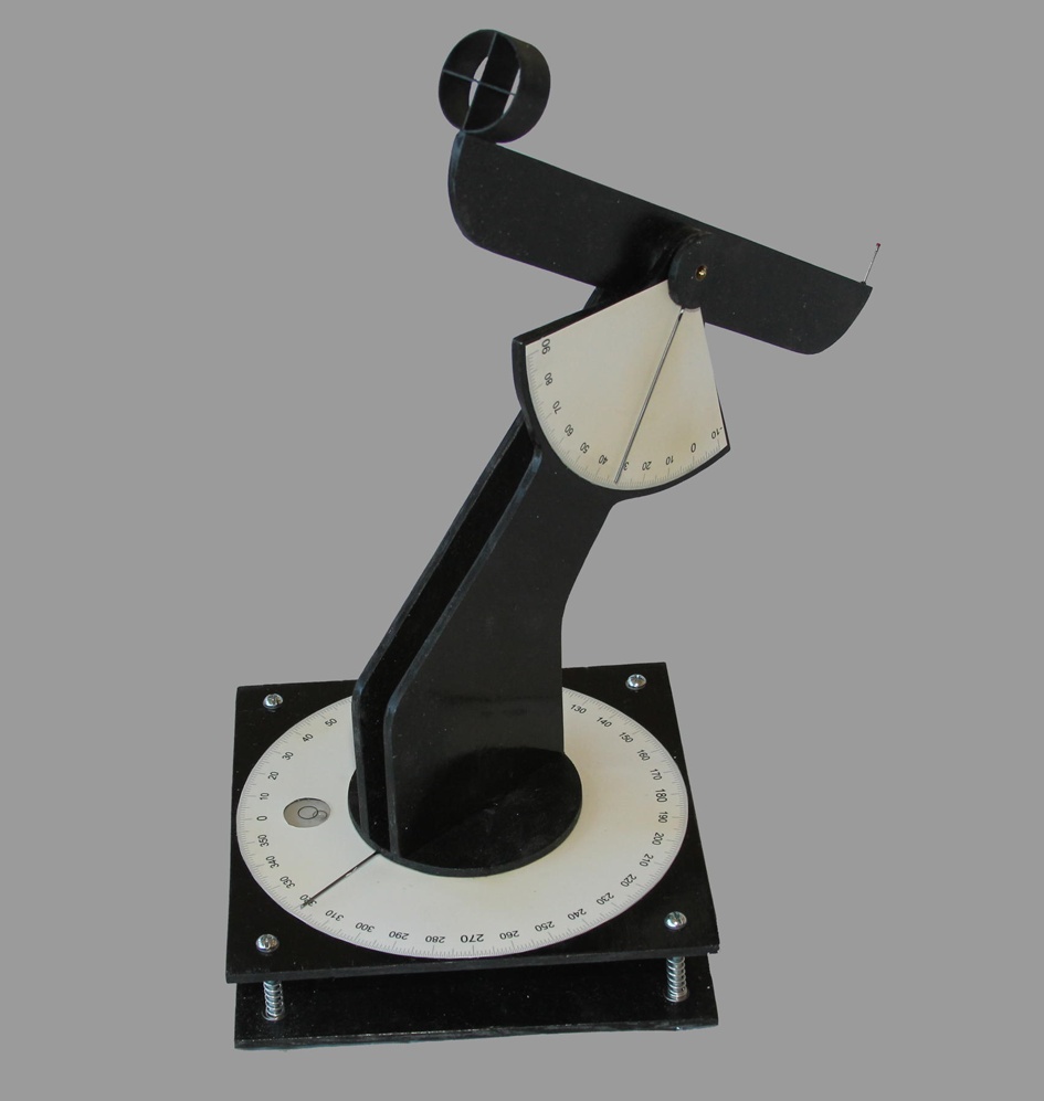
Building a theodolite is no harder than building one of the more sophisticated model rockets. It takes a few materials and parts you may not have on hand, though. Look through the parts list (Table 8-2) and tools list (Table 8-3) carefully.
Don’t be afraid to make substitutions, especially for the level, the indicator wire, and the brass tubes used as joints. You will need to adjust the plans a bit if you make substitutions, but there is nothing magic about the particular parts shown here. If you have something in your parts bin that will work, use it.
The parts list and directions that follow show how to build one theodolite. If you need two (you do actually need two theodolites to track a rocket), be sure to double the quantities of all parts.
| Part | Description |
1/4” plywood | This is used for most of the structural parts. Visit your local hardware or woodworking store; most will have sheets of plywood about 2 ft x 3 ft that have a nice smooth surface on both sides. This is enough to make two trackers. Get cabinetry-grade hardwood, not the rough grade used for construction. |
3/4"-thick wood | You will need two 1” squares. One piece will need to be sanded down to a thickness of about 0.6”. |
1/16” piano wire | This is used for indicators. A little thicker or thinner won’t hurt, so don’t run out and buy more if you already have something that is close. This is sometimes called music wire or simply steel wire. You can find it at most hardware stores and hobby stores. |
Photo paper, 2 sheets | The indicator dials will be printed from an inkjet printer. My tests showed photo paper works a lot better than card stock or plain paper, but it’s not essential. |
1/4-20 nut | Most photo tripods thread into a nut that is 1/4” in diameter and has 20 threads per inch. This tracker is designed to sit on top of a photo tripod, and this nut is what will hold it. |
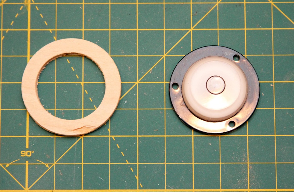
Bull’s-eye level | Also called a surface level, this type of level is usually circular with a bubble that is in the center of the level when the surface is level. The plans show Ace Hardware part 24539. You can substitute, but a few dimensions may change if you do, so be sure you have the level before you start cutting. |
1/8” plywood | This is used for a small ring to mount the level. You may need a different thickness if you use a different level. While I used plywood, you could also use balsa wood. There won’t be much stress on the part. |
Red seed bead | This is the top of the rear sight. I used a small red seed bead from an art kit. You can substitute anything that is about 1/32” to 1/16” in diameter and easy to see against black paint and blue or cloudy skies. |
1/32” plywood | This is used for the cross hairs on the front sight. If you make a substitution, pick something thin and strong. |
BT-60 body tube coupler | This forms the outside of the front sight. A little larger or smaller won’t hurt. |
Precision metals 5/16” brass tube | See the next item. |
Precision metals 9/32” brass tube | A well-stocked hobby store will have a section with a dizzying variety of brass, copper, or aluminum tubes. Pick two sizes that are around 1/4” to 1/2” in diameter, where one tube slides smoothly inside the other. These will be used to create smoothly turning parts for the tracker. If you don’t have access to a well-stocked hobby store, check http://www.onlinemetals.com or other online stores. If you are ordering online, allow about 1/64” difference between the outside diameter of the smaller tube and the inside diameter of the larger tube. |
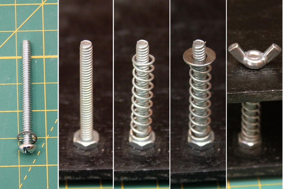
2"-long 3/16-20 bolt (4) | These will hold the two plates together. The nuts and washers that follow should fit this bolt. |
3/16-20 nut (4) | |
3/16-20 wing nut (4) | |
3/16” lock washer (4) | |
3/16” flat washer (4) | |
Spring (4) | You are looking for four small springs, about 1 1/2” long, that will fit over the 3/16-20 bolt. The ones shown are Prime-Line 0.047” x 11/32” x 1-1/2” compression springs from Ace Hardware. |
Small wood screw (3) | These are used to mount the level. I used 1/4” #2 pan head sheet metal screws from Ace Hardware. Anything that will hold the level in place will do, even glue. |
Felt | A 4” square of felt to help form a smooth mechanism. |

Cutting the parts
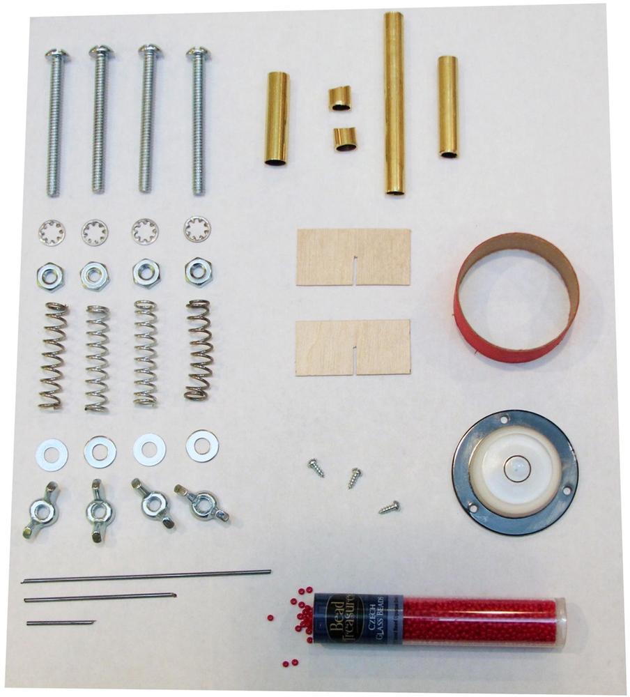
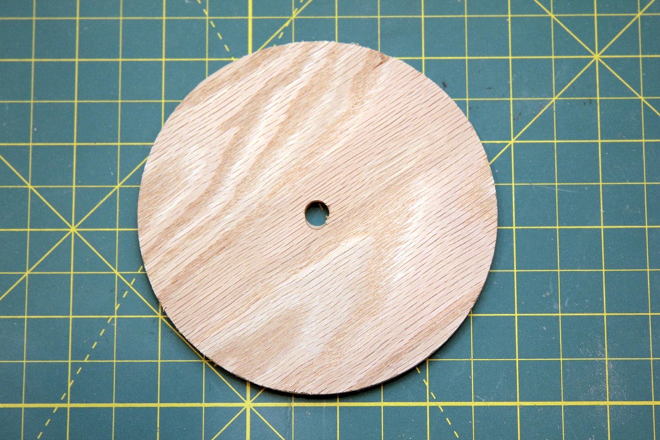
Most of the parts are cut from 1/4” plywood. Many of the parts are circular. You have a choice about these: you could cut the parts using a scroll saw, but an easier way is to use the specialized hole saws used to cut large holes in wood, like the one shown in Figure 8-13. This is not the cheapest way to do it, but if you have the tools available, this is a great time to use them. These hole saws also have a nice side benefit: they drill a 1/4” guide hole in the exact center of the disk with no mess or measuring.
The large circular base should be about 4” in diameter. A 4 1/4” hole saw will leave a center piece that is just about a perfect 4” circle. A little smaller or larger is OK, but you will need to adjust the size of the upright supports if the circle size is not 4”.
Hole saws cut all the way through the wood. Unfortunately, that isn’t really good for the surface underneath the wood! To save the surface, put a piece of scrap wood under the piece you are cutting, as seen in Figure 8-13.
Cut four additional 1 1/4” disks with a 1 1/2” hole saw or scroll saw. The size is not absolutely critical, but again, the side supports will need to be adjusted if you use a different size. The rounded edge at the top of the side pieces should be the same diameter as the disks you cut.
Once all five disks are cut, drill a 9/32” hole in the exact center of each disk. These holes should accommodate the smaller of the brass tubes, so change the hole size if you used a different size than shown in the parts list. The fit will be very tight, which is a good thing, but don’t be afraid to ream the hole out if it seems too tight. You can ream the hole by pushing the drill bit in and out several times.

Cut two side supports from 1/4” plywood (a scroll saw works well here). Figures 8-17 and 8-18 show the dimensions for the side supports, which you can adjust if the size of other parts changes. However, if you make adjustments, be sure the supports will hold the sight bar far enough from the center of the theodolite so you can measure angles up to 90°. That’s why the supports have the odd jog to the side.

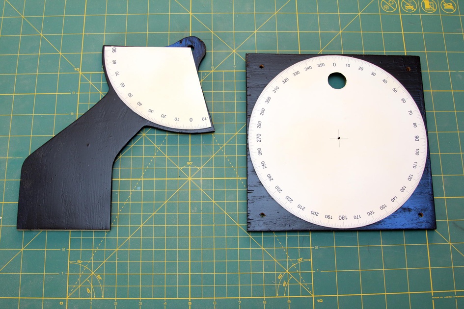
The support with the wing-like structures is designed for the elevation angle protractor.
You can find full-size plans for the side supports and all other parts online at the author’s website.


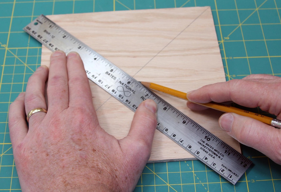
Cut two 8” square plates from 1/4” plywood. Carefully locate the center of each plate by drawing a line from one corner across to the other in both directions. Place an additional mark 7/8” from each corner. These are the locations where the holes for the connecting bolts will eventually be drilled.
You will need a surface level to make sure the tracker is perfectly level before each use. The tracker has an indicator that will sweep around the top plate, and it reaches almost to the edge of the plate. The level needs to be mounted flush with the surface of the top plate, unless it is small enough to fit in a corner between the indicator and the connecting bolts. That means you’ll be drilling a hole through the plate to accommodate the level, and mounting it from the bottom. This way the top of the level will be flush with the top of the plate.
There are a lot of different kinds and sizes of surface levels. You don’t have to use the same bull’s-eye level from the parts list. However, if you make a substitution, you will have to make changes in the next few steps to accommodate the level you pick.
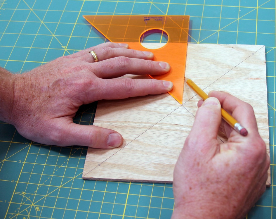
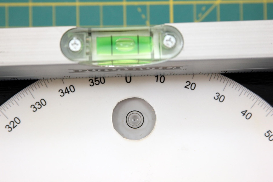
The hole for the level will be right below the zero point for the indicator dial. Find the location using a 45° angle to draw the vertical line. Measure 2 3/4” from the center and make a cross mark. This is the location of the center of the hole for the level. You can also use a protractor or even a folded sheet of paper if you don’t have a 45° angle handy.
Drill 3/16"-diameter holes at the marks 7/8” from the edge of each corner. Drill these holes in both the top and bottom plates. Drill an additional 1 1/4” hole for the level.
Drill a 5/16” hole in the exact center of the top plate. This hole needs to be the same size as the larger of the brass tubes, so if you used different-sized tubes, adjust the hole accordingly. While it’s always nice to be precise, precision really matters with this hole. Get it as close to the center as possible. Use a drill press for this hole if you possibly can. Try to get the hole as vertical as possible if you are using a hand drill instead of a drill press.
Measure the outside diameter of the 1/4-20 nut that will mount the tracker to the camera tripod. The one I used fit into a 1/2” hole. Drill a hole in the center of the lower plate to accommodate the nut.

Cut the sight bar from 1/4” plywood. The sight bar is 12” long and 1 1/2” tall. I rounded the corners using 3"-diameter circles because I thought it looked better, but that’s not essential. Drill a 9/32” hole in the center to accommodate the smaller of the brass tubes.

The level will poke through the top of the plywood. Test fit the level to double-check the height with the specific level and plywood you are using. In my case, the level protruded from the top by about 1/8”—easily enough to interfere with the smooth movement of the theodolite, since it caught the needle as the device turned. To solve this problem, cut a shim from an appropriate thickness of wood. I used a 2” hole saw to cut a disk from 1/8” plywood, then used a 1 1/4” drill bit to drill out the hole for the level.
Drilling a hole in the center of a circular disk can be tricky. There will be a 1/4” starter hole left by the scroll saw, so finding the center is easy enough. The disk will tend to turn easily while drilling out the center hole, though. I suggest you hold the disk with a large pair of pliers or a clamp while you’re drilling the center hole.
Of course, the shape of the outside of this disk is not critical. You could also cut a 2"-square piece, or cut the disk with a scroll saw. The only really critical aspect of this part is that the hole in the middle be the same size as the level.
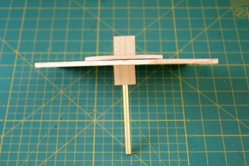
Cut two 1"-square pieces from 3/4” thick clear wood (no knots or other major imperfections). One of these pieces will fit between the two sides to support them. We’ll call this the top block; the other piece is the bottom block that fits below the top plate of the theodolite. The top block needs to be sanded to match the thickness of three sheets of plywood, since there are three pieces of plywood—one sight arm and two disks—at the top of the theodolite. If your plywood is really 1/4” thick, you won’t need to do any sanding, since the three 1/4"-thick pieces of plywood will be the same thickness as the piece of wood. If the plywood is more like 1/5” thick, like mine was, you will need to sand the wood quite a lot to get it thin enough.
Drill a 9/16” hole through the center of the top block. This hole will fit the thinner of the brass tubes. Drill a 5/16” hole in the bottom block to fit the larger brass tube.
The angle of the holes through these wooden blocks is critical, so use a drill press if at all possible. If you don’t have a drill press, make several wooden blocks and pick the one with the most precisely vertical hole. It’s worth taking the time to get this step right, since the smooth movement of the theodolite depends on a perfectly aligned hole.

Cut a 3/4” piece from a BT-60 body tube coupler. This forms the outside of the forward sight. Mark the tube coupler as if you planned to install four fins, but put the marks on the inside of the tube. These marks show where the cross hairs will be glued.
It’s not absolutely critical that you use a BT-60 body tube coupler. A BT-55 coupler will work fine, as will a BT-70 coupler. You might even find some other stiff tube about the right diameter that will work well as a forward sight. I’d stay away from body tubes unless you plan to reinforce them, though. The forward sight will get bumped from time to time, and a body tube won’t stand up to as much abuse as a tube coupler.
Cut two pieces of very thin plywood to 3/4” high, with the length matching the inside diameter of the tube coupler you selected. I used 1/32” aircraft plywood from a hobby store. Use a hobby knife to cut slots in the center of each piece so they can be assembled in a cross. This will form the cross hairs for the forward sight.
Finally, cut the brass tube to length using either a Dremel tool with a cutting blade, a chop saw, or a hacksaw. You will need three pieces from the thicker tube. Two should be the same thickness as the plywood; these will be used in the upright supports as strong, smooth bushings. Cut another piece that will fit through one of the 1"-square pieces of wood and the upper plate of the theodolite. For 1/4” plywood, it will be 1 1/4” long. Use sandpaper or a grinding stone on a Dremel tool to smooth off the ends so the smaller brass tube slides into and out of these pieces easily.

Cut one piece of the thinner tube to match the thickness of seven layers of plywood (that is, the thickness you get by compressing the wood slightly). Small differences in the wood thickness will add up when you layer seven pieces of wood together. The best way to get a tube the right length is to assemble the top portion of the theodolite, push the tube through until it is flush with one end, and then mark the tube where it sticks out. Compress the wood enough that the sight arm can be moved easily, but will stay in place when you release it. Now cut the tube, sand the ends, and check to make sure it slides into the two small bushings easily and rotates smoothly.

The last piece of thin tube needs to be long enough to go through both 1” blocks and two pieces of plywood. Once again, assembling the parts and marking the tube is the most accurate way to cut the tube to the right length. Unlike the top piece, though, this piece can be a little too long or short without any real effect on the operation or appearance of the finished theodolite. Any excess tube will just stick out between the two plates. Sand the ends, and make sure the part slides into the longer thick brass tube and turns freely.
First steps in assembly
There are some odd nooks and crannies in the theodolite that make it difficult to prime and sand once all of the pieces are fastened together. The solution is to assemble some of the small parts, then prime and paint the wood. Once the paint dries, the pieces can be glued together and a little touch-up paint used to cover up any small areas of bare wood.
Start by installing the 1/4-20 nut in the lower plate. This is the nut that serves as an attachment point with the tripod. You will want this nut to be flush with the bottom of the plate so the tripod bolt will screw down against the nut. If the nut is recessed, the tripod bolt will pull on it as you tighten it into place. Since a threaded bolt can exert a lot of pressure, this would either splinter the wood or break the glue joint if the nut itself is not taking the pressure.
Place a small piece of wax paper or plastic wrap on your work surface. Push the nut into place and apply a generous amount of fast-curing epoxy around the sides of the nut. Be sure you don’t get any inside the threads! Reinforce the wood by spreading glue in a thick layer about 1/2” over the wood that surrounds the nut on both the top and bottom sides of the plate.
Place the assembly over the wax paper to dry. Make sure the nut is pushed all the way down so it is in contact with the wax paper. Double-check to make sure there is no epoxy in the threads. If there is, you can clean it out with a Q-Tip and rubbing alcohol, or pull out the nut and substitute another. A flashlight might help when checking the threads for glue.

Print the two protractors from the online files at the author’s website. The quality of the paper you use really matters on these, especially if you paint the theodolite black as in our example. After trying normal inkjet printer paper, card stock, and photo paper, I opted for photo paper. It’s thick enough that the black paint does not show through. You can get by with card stock, especially if the paint color is light, but we’re going to glue and treat the paper in such a way that normal inkjet paper just won’t do.
Place the 4” central disk in the center of the 360° protractor. Cut a 2"-long piece of 1/16” piano wire to use as a horizontal angle needle. Drill a 1/2” hole into the edge of the 4” circular disk, and then use a ruler to align the needle against the protractor. The needle should point straight out from the center point of the disk, just barely touching the base of the 1/2-degree marks on the protractor. Glue the needle in place with a small shim under the tip so it won’t rest directly on the protractor as the disk rotates. I used epoxy because that’s what I was using on almost everything else, but wood glue will work, too. There isn’t a lot of strain on this needle.

While the glue dries, repeat the process for one of the four small disks. The needle will need to be 3 3/8” long this time, also made from 1/16” piano wire. Set both of the disks with their needles aside to dry.

The level has a cute beveled edge around the top. That will be a weak spot under the protractor, so we need to fill it in with wood putty.
Begin by gluing the 1/8"-thick plywood ring into place so the center of the ring matches up exactly with the center of the hole in the top plate. The ring gets glued to the bottom of the plate, although the plate is reversible up to this point. Let the glue dry enough so you can work with the piece. While wood glue will work just fine, if you use 5-minute epoxy, you can proceed in about 10 or 15 minutes.
Cover the level in plastic wrap. This prevents the wood putty from adhering to the level. Push the level into place, making sure it is flush against the wood ring, then screw it into place with three #2 1/4"-long wood screws. At least, that’s what I used. Any screw that will fit is fine, of course.
Flip the board over and press wood putty into the area around the top edge of the level, filling in the area left by the bevel.
Allow the wood putty to dry overnight. Remove the level and use a sanding block to sand the wood putty smooth.

Once the needle on the central 4” disk is dry, flip the disk over. Cut a felt disk slightly smaller than the wooden disk and glue it in place with a thin layer of wood glue. This gives a smooth surface that will allow the theodolite to rotate easily, but stop right away when it is in position.
Once the glue dries, trim the excess felt away from the central hole.

Use small amounts of wood glue to fasten the cross hairs to form the forward sight. Glue the wood to the paper, but don’t bother gluing the wood where the two pieces cross. Glue isn’t needed in the middle, and a stray glob of glue will be very annoying when using the finished theodolite.

Finishing
Dry fit all of the parts so you understand how they fit together to form the final theodolite. The theodolite will be held together by glue. Mark the areas that will eventually be glued and tape them off. There is a 1"-square area at the base of each of the vertical supports where the top block will be glued. (One of them is on the back side of the support in Figure 8-34.) The top block gets painted on the top and on two of the faces adjacent to the top, but the bottom and sides are taped. The bottom block is taped on top, but painted on the other five sides. The edges of the four small disks need to be painted, but only the two outer disks need to be painted to the center, and then only on one side.
The most complicated taping job is the top of the 4” disk. Tape off the area where the top 1” block and the two vertical supports will be glued. These should align with the indicator needle. Absolute precision is not critical; it won’t affect the accuracy of the instrument. Still, it needs to look straight.
Once all of the areas that will be glued are taped, apply a coat of sealer to the wood. I used wood sealer, but the same sanding filler you use on rocket fins will work, too. After sanding—and perhaps replacing some of the tape that gets roughed up—paint the wood.

Installing the protractors
Glue the protractors in place. It is very important that the center of each protractor is directly over the hole in the wooden piece. With that exception, it just needs to look straight. It won’t affect the accuracy of the instrument if the protractors are rotated by a degree or so.
Spray glue works really well for attaching the protractors, but a thin layer of wood glue will work, too.
Once the glue sets, spray the protractors and the wooden surface on the same side as the protractors with a light coat of clear varnish. This needs to be a light coat, because a thick coat might cause the ink from the inkjet printer to bleed. Once the first layer of varnish sets, add a nice, thick top coat.
Let the paint and varnish dry very thoroughly before proceeding. The paint could bind if the disks are clamped in place before the paint is absolutely dry. Let it dry at least overnight.
Final assembly
The thick brass tube will be glued into the lower wood block, so rough up the entire outside of the tube with sandpaper. Also rough up about 1” of the long, thin tube. Part of it will be glued into the top block, but the lower part needs to stay smooth so it turns easily when inserted in the lower block.
Dry fit the parts. The thick brass tube should be flush with the top surface of the plate. It’s OK if it sticks out of the bottom of the bottom block a bit, or doesn’t quite reach the end. The thinner brass tube should be flush with the top of the top block on the 4” disk, extending out of the bottom of the 4” disk. Make sure they are cut and drilled straight enough that the 4” disk turns smoothly in a 360° circle. It’s not too late to sand or trim the parts, or even replace one completely, but it will be after the next step.
Use fast-drying epoxy glue to fasten the wooden blocks to the bottom of the top plate and to the top of the 4” disk and to glue the brass tubes in place. Double-check the fit of the parts before the glue sets. The 4” disk must rotate freely and without wobbling. If the disk binds or wobbles, adjust the pieces to get rid of the problem. Remove the pieces and start over if you have to, but don’t let the glue set until the pieces are perfectly aligned.

Allow the glue on the 4” disk to set thoroughly. Dry fit the side supports, making sure the holes in the top portion align. Use fast-drying epoxy to glue the side supports in place. A clamp is very handy at this point, but patience and a steady hand will work, too.

Use a level to make sure the bubble level is perfectly aligned with the top surface of the plate, and then screw the level in place from the bottom. Be sure to check the alignment both horizontally and vertically.
Fasten the top and bottom plates together with 2"-long 3/16” bolts. Use a lock washer on each bolt, and then slide it through the top plate. Add a nut and tighten it. This keeps the bolt in place as the wing nut is used to tighten and loosen the bolt for fine-tuning the plates when leveling them. Repeat this process on all four corners.
Add a spring and washer to each bolt, and then slip the bottom plate into place. Add four wing nuts, tightening them just enough to hold the bottom plate in place.
Cut a piece of 1/16” music wire to use as the rear sight. It should be about 1/2” longer than half the diameter of the forward sight. Glue a red bead or some other small, colorful object to the end of the wire and let it set.
Drill a small hole about 1/2” deep in the top of the sight bar. This hole should be about 3/8” from the end. Use a toothpick to shove some fast setting epoxy glue to the hole, and then sink the rear sight into the hole. Before the glue sets, put the forward sight right next to the rear sight. Make sure the red bead aligns exactly with the center of the cross hairs. Once the glue sets enough to handle the piece, glue the forward sight in place at the opposite end of the sight bar. Prop the piece up while it dries.
Make sure all of the paint and glue has dried completely before moving on to the last step in assembly. Tacky paint will dry solid and weld the top pieces together. It’s also good to have a little time when assembling the top portion of the theodolite, so use slow-cure epoxy if you can.
Begin by dry fitting all of the parts to make sure the fit is good. The two short brass bushings cut from the larger-diameter brass tube go in the holes in the side supports. The remaining brass tube gets shoved through one of the circular disks, a side support, another circular disk, the sight bar, a third circular disk, the other side support, and the final circular disk, as shown in the final assembly in Figure 8-41.

Make sure all parts fit and rotate smoothly. It’s not too late to replace a bad piece or sand a piece that almost fits. Read through the next steps of the assembly before you do anything, to make sure you understand them completely. Have everything you need laid out where you can reach it easily, because once you start, you will need to finish before the glue sets.
Scuff the end 1/8” and middle 1/4” of the long brass tube with sandpaper so the glue has something to cling to. Apply a small amount of epoxy to the inside of the disk with the indicator, and insert the long brass tube. Make sure there is no glue at all on the inside surface of the disk or brass tube. Slide the assembly into place, and slide on the next wooden disk. Apply a small amount of epoxy to the brass tube and slide on the sight bar. It’s OK if the sight bar gets glued to the wooden disk.
Slide on the third wooden disk and shove the tube through the bushing on the final side support. You will be sliding the components back and forth to get them through the various holes. Be sure no epoxy has worked its way onto the part of the brass tube that fits through the bushing. If it has, wipe it away with rubbing alcohol.
Put a small amount of epoxy inside the final wooden disk and slide it into place. Putting the epoxy inside the disk and sliding the disk over the brass tube should guarantee there is no epoxy on the inside surface of the disk or on the part of the brass tube that goes through the bushing. Keep a close watch for leaks.
Check the movement of the mechanism. The disks should be tight enough that the sight bar will stop when released, but they should be loose enough that the sight bar can be moved up and down easily.
Working quickly but very accurately before the glue sets, place a bubble level on top of the sight bar and make sure the sight bar is perfectly level. While it is level, rotate the sight bar relative to the disk until the needle points exactly to zero degrees. It is critical that this be done accurately. This is how the theodolite reports its vertical angle; you don’t want it to report anything but 0° if the sight bar is level.
Remove the level and let the glue dry.

Check the movement of the mechanism when the glue is just about at its cure time. For example, if you are using 30-minute epoxy, check the movement 25 minutes after you mixed the glue. Does the sight bar move smoothly? Does moving the sight bar move the indicator needle? Are they moving together with no slipping? If there is a problem, quickly disassemble the components and clean them with rubbing alcohol. Figure out why the problem occurred and, after correcting the problem, repeat the assembly process.
Math Behind Dual-Axis Tracking
If you recall, the biggest source of error with a single-axis tracker occurs because the rocket doesn’t necessarily go straight up, so the angle between the tracker, launcher, and rocket is not exactly 90°. Another way of looking at this is that we don’t precisely know the length of the baseline to the point exactly under the rocket. With two dual-axis trackers, we no longer assume the rocket’s apogee is exactly over the launcher. Instead, we measure the position using the two horizontal angles. Knowing the distance between the trackers and the angles between them and the rocket at apogee, we can find the actual baseline length. Then we can calculate the altitude from either tracker. In practice, we calculate the altitude from both trackers and take the average, since there will probably be some error that causes the two trackers to report slightly different altitudes.
There are several ways to do the math to find the altitude from these angles. Two are approved by NAR for use in contests. Let’s take a look at one of them in detail, and the other briefly, to figure out what dual-axis tracking is all about.
The vertical midpoint method
The vertical midpoint method is the most obvious way to find the altitude using two theodolites. Figure 8-43 shows the two trackers, T1 and T2.
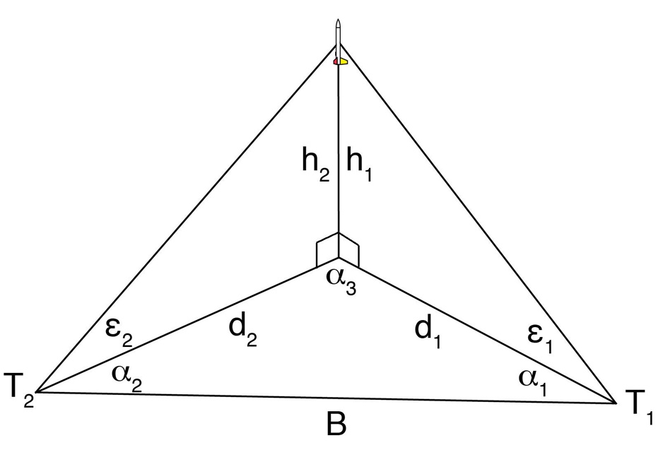
When the rocket hits apogee, both trackers report two angles. One angle is the horizontal angle between the tracker and the rocket, labeled α1 for the first tracker and α2 for the second tracker. Each tracker also reports the elevation angle of the rocket at its peak. This is labeled ε1 for the first tracker and ε2 for the second tracker. The distance between the trackers is B.
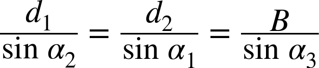
We can use the law of sines to find the distance from each tracker to the point just below the rocket. The law of sines relates the sine of an angle and the length of the side of a triangle opposite the angle to the other angles and sides of the triangle. Looking at the triangle on the ground, this gives:
All of those values are known except α3, the angle right under the rocket. We can use the fact that the sum of the angles in a triangle is always 180°, and a few trig identities, to get that term into a more manageable form:


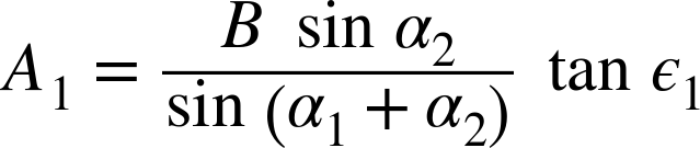
The baseline for the first tracker, then, is:

Now that we have an accurate baseline for the elevation angle, we can solve for the altitude as if we were using a single-axis tracker:
The altitude measured by the second tracker is calculated the same way, giving:

These are usually different, since the angles are never measured with perfect accuracy. Since we don’t know which one is correct, the only fair thing to do is report the altitude as the average of the two:
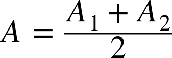
We used error analysis to find the expected error for the single-axis tracker. NAR uses a slightly different way to get a handle on the error for altitude contests and records. If the two altitudes differ by more than 10%, the result is discarded, and the rocket must be flown again. This is called an open track. If the difference is 10% or less, it’s called a closed track, and the result is the average of the two altitudes rounded to the closest meter. If the result is exact to a half meter—say, 112.500 meters—the result is rounded up (here, to 113 meters).
The equation used to calculate the error is:
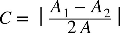
If C is less than or equal to 0.1, the track is closed; otherwise, the track is open and the rocket must be reflown.
The geodesic method
This method finds the altitude using a slightly different procedure. It’s more complicated to understand, but it gives a closed track more often than the simpler vertical midpoint method.
The geodesic method starts by assuming the two theodolites will not get exactly the same result. That means the line from one tracker to where it thinks the rocket is located won’t actually touch the line from the other tracker to the position of the rocket. It finds the closest distance between the two lines, and reports the altitude as the midpoint of that line.
We won’t go through all of the math here. Check online or in a textbook on analytic geometry for ways to find the distance between two lines if you would like to work out the derivation of the equations.
Here’s the math used by NAR for finding the altitude using the geodesic method:


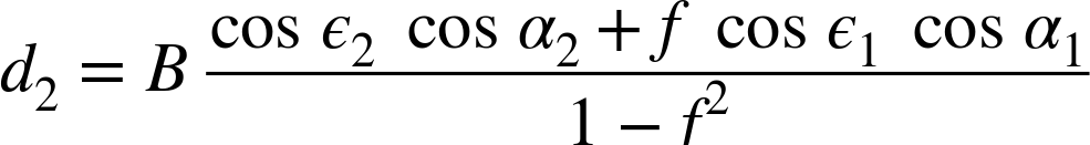

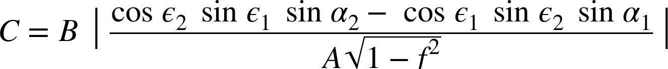
Once again, if C is less than or equal to 0.1, the track is closed.
The vertical midpoint method and the geodesic method might give slightly different results. How is that handled in a real contest? If one result is closed and the other is open, the closed result is used and the other discarded. When both methods give closed results, the general practice seems to be to use the geodesic method for all results. This is a detail left to the contest director, though. That person might pick the method with the lowest value for C, or the higher of the two closed altitudes. Based on the current NAR Pink Book, as long as the directors are consistent, they can use whatever method they choose. Of course, that should be decided before the competition, not after!
Using Dual-Axis Trackers
Theodolites are usually set up to the south of the launch pads so the sun won’t get in the eyes of the trackers. They should be at a distance of 50% to 200% of the expected altitude for the rockets they are supposed to track. This way, the theodolites won’t have to measure overly small or overly large angles, which can make it harder to get an accurate altitude measurement. It’s common to use a baseline of 300 meters, which allows fairly accurate tracking of rockets that will hit altitudes of 150 meters to 600 meters—about 500 feet to 2,000 feet. That’s a pretty good range of altitudes.

The trackers need to communicate with each other and with the LCO so they can agree on when the rocket reaches apogee. Unless they are as loud as Mom used to be when she shouted from the back door for me to get my tail back home, they will need walkie-talkies, or some similar method for communicating.
It takes at least three people to track a rocket with a pair of theodolites; six people are better. With just three people, the trackers should agree beforehand that they will track the rocket until the ejection charge fires. The two trackers then report their angles back to the LCO, who calculates the final altitude. You could even get away with having the trackers write down the angles and report them later. The problem with this method is that the rocket may arc over at apogee and start back down before deploying the parachute. It would be nice if the actual apogee could be recorded. Unfortunately, the rocket might arc in such a way that the two trackers disagree on when it reaches the highest point.
You can avoid this problem with six people. One person is the LCO, who announces the launch. Two trackers operate the theodolites. Three additional people operate the walkie-talkies and watch the rocket. As soon as one of the trackers thinks the rocket has hit apogee, she calls out to stop the track. The trackers then lock in the angle on the theodolite, and the people working with each tracker report the results back to the LCO table for calculation. In a well-oiled group, the result is available very quickly, and the LCO can announce the altitude to the spectators.
Using more than two theodolites
It’s pretty tough on a competitor to have a perfect flight, only to find that one of the trackers got the sun in his eye or had some other issue that caused an open track, forcing the competitor to fly again. Larger contests will try to use more than two theodolites to track the rocket. If one messes up, the others can still get a result.
One popular method shows how this is done. Four theodolites (call them A, B, C, and D) can be positioned in a huge square around the launch area. Before the launch, each pair of theodolites reports the angles to each of the other theodolites. During the flight, they each report the angle to the rocket’s apogee. You end up with a total of six different pairs of theodolites (A-B, B-C, C-D, D-A, A-C, B-D) providing data! If they all succeed, that gives six different closed tracks and, in most cases, six slightly different altitudes. All of the closed tracks are then averaged for the final contest altitude.
Program for Dual-Axis Trackers
There are lots of programs around for reducing the angles from the trackers and reporting the altitude. There is one in Appendix A, written in a fairly generic modern BASIC, that works well. This one is also built into techBASIC. You can find a similar program in the NAR Pink Book. A quick online search will turn up several more.
Run the program from Appendix A. It will ask for the baseline distance and the angle from the tracker to the rocket. It then asks for the azimuth and elevation angles—the horizontal angle between the tracker and the rocket and the angle between the horizon and the rocket—for both trackers. The program then reports the altitude using both tracking methods.
Here’s some sample output from the tracking program in Appendix A:
Baseline length: 300
Tracker 1 azimuth: 90
Tracker 1 elevation: 45
Tracker 2 azimuth: 50
Tracker 2 elevation: 40

Vertical Midpoint Method:
  Altitude: 374.574097
  Closed track; C = 0.045513

Geodesic Method:
  Altitude: 380.048248
  Closed track; C = 0.063234
Altimeters
Visually tracking a rocket from the ground with a protractor or theodolite is cheap and fairly accurate. There is a way to track the flight electronically, though. Modern altimeters use a barometer to sense the changes in air pressure as the rocket ascends and descends. They are often supplemented by an accelerometer that senses the motion of the rocket. I’ve even flown small sensor packages that could sense the magnetic field and rotation of the rocket.
The advantage of altimeters is that their accuracy does not depend on multiple people doing a perfect job. They work even if you lose sight of the rocket, and they give a lot more information. Since the altitude is updated constantly, you can also figure out how fast the rocket went and what forces the payload had to endure.
Altimeters do have disadvantages, though. While some are remarkably small and light, they do add weight to the rocket. Altimeters also require a vent hole leading outside the rocket so the barometer works. Finally, while they are not terribly expensive, there is always the chance they will be lost. To my knowledge, no one has ever lost a theodolite during a model rocket launch!
Most model rocket altimeters are designed for high-power rocketry. Many high-powered rockets use small pyrotechnic charges to deploy the parachute rather than an ejection charge built into the motor. The altimeters for high-power rockets are generally powered by a fairly heavy external battery and have electronics to fire at least the pyrotechnic charges.
The tiny MicroPeak altimeter is one of my favorite altimeters for smaller rockets. It can’t fire pyrotechnic charges like the high-power rocket altimeters, but it’s a lot smaller and uses a tiny coin cell battery. The whole altimeter, with the battery, fits into a BT-20 nose cone, and only weighs 1.9 grams. Yes, that includes the battery! They cost about $50, and are available from several of the online rocket stores listed in Appendix B, such as Apogee Components.

We’re going to build a high-performance rocket named Hebe (pronounced HEE-bee) in Chapter 15. Let’s take a look at one flight of Hebe with a C6-7 motor to get an idea of what this altimeter can do.
The MicroPeak fits into BT-20-size plastic nose cones. Stuff a little cotton in the top for padding, then tape the bottom securely to the nose cone. Don’t let the pressure from the ejection charge get to the altimeter. One way to prevent this is to seal the opening in the base of the nose cone with a strip of paper covered in epoxy.

After the flight, the altimeter flashes an LED with the altitude in decimeters. It flashed 6-10-7-5 for this flight. Ten flashes indicate a zero, so the altitude was 607.5 meters, or 1,993 feet. I had that answer as soon as I popped the altimeter out of the nose cone and counted the flashes.
Back at my computer, I hooked the altimeter up to a small device that downloads the flight data to a free program. The main display is a configurable plot, showing the acceleration in blue, the speed in green, and the altitude in red. You can clearly see the motor thrust by looking at the blue line in Figure 8-47. You can even see the rocket bouncing around as the streamer flapped a bit. It’s also worth taking a close look at the acceleration right after motor burnout. Why does it go negative by so much? That may be an overreaction of the sensor to the switch from high forward thrust to a slight negative thrust.
The altitude also shows an interesting—and for this accelerometer, unusual—anomaly. The flight ends at an altitude of about 230 meters. The rocket absolutely did not land on a hill that high above the launch point!

The Statistics tab gives a lot of great information about the flight. For example, it’s pretty cool to see that the maximum speed was just over 500 mph, almost 2/3 the speed of sound! You can also see the descent rate, which is a bit fast on the streamer. That was a conscious choice for this flight. It’s a small, light rocket, so coming down a little fast wasn’t going to hurt anything. It was also going really high. There is a good chance the rocket would have been lost if it had been on a parachute.

There is a configuration tab that lets you turn various plotting features on and off or switch to imperial units. There is also a raw data tab that shows the actual values recorded by the accelerometer and barometer. You can offload the data with an Export command to run your own analysis.

The MicroPeak isn’t the only small altimeter out there, and more are being added all the time. Shop around on the Internet a bit if you decide to buy an altimeter. Check Appendix B for a list of online stores.
Comparing the Methods
This chapter shows three different ways to find the altitude of a rocket. Chapter 14 will show three different ways to predict the altitude before a flight. How do they stack up? Let’s take a look at the data from some actual rocket flights (Table 8-4) to find out. These flights are from the payload conversion of Juno flying with a MicroPeak altimeter. On this particular day, we didn’t have theodolites set up because it takes too many people, but of course they would have been more accurate than the single-axis tracker. The flights were also simulated using OpenRocket, RockSim, and the 1D simulation from Chapter 14. The weather conditions were taken from a nearby airport (not too near!) so the simulators had a chance to accurately predict the altitudes. All altitudes are in meters. Error estimates for the single-axis tracker come from Table 8-1. Errors from the mean are the standard deviation from all of the observed and predicted altitudes.
The point here isn’t to determine which device was better. All altitude predictions and measurements have error, and we really have no way of knowing the exact altitude. While I would certainly rank the single-axis tracker last for accuracy, the result we got from it is not far off from the other methods. The simulations tend to disagree, too, but again, not by all that much.
| Method | A8-3 | B6-4 | C6-5 |
1D simulation | 57 | 156 | 315 |
RockSim | 59 | 173 | 395 |
OpenRocket | 57 | 150 | 326 |
Altimeter | 64 | 169 | 392 |
Single-axis tracker | 59 | 146 | 419 |
Mean | 59±3 | 159±12 | 369±46 |
The point is that we have three different ways to measure altitude, each with its own advantages, disadvantages, and typical error. It’s an engineering decision to pick the best method for measuring altitude for a given flight, based on budget, the number of people available, and the accuracy needed. As the rocket scientist, you get to make that choice.