Chapter 23. Onward and Upward
This book has led you through all of the major kinds of rockets in the fields of water rocketry, air rocketry, and low-power solid-propellant rocketry. You’ve learned how to build and fly rockets using all of the major recovery techniques, and you’ve seen propulsion systems like clustering and multistage rockets.
This chapter closes with a bridge to mid-power rocketry, a challenge for your new skills, and, just for fun, some really odd rockets.
Most mid-power rockets and nearly all high-power rockets use reloadable motors. While these are uncommon in low-power rocketry, there are a few reloadable motors you can use with the rockets in this book. Let’s start by taking a look at one of them.
Reloadable Motors
All of the motors used so far in this book have been single-use black powder motors. There is another kind of motor that is less expensive per flight, and often smaller as well. Reloadable motors use the same aluminum perchlorate solid propellant rocket fuel that was used in the solid propellant strap-on boosters for the Space Shuttle. For model rockets, chemicals are sometimes added to produce different-colored flames or more smoke. Like the Space Shuttle motors, reloadable model rocket motors are reusable. The motor case is made from aluminum, while the forward closure and aft closure are made from brass or aluminum. We’ll see what these parts are in a moment. The disposable parts include propellant, a smoke charge, an ejection charge, a nozzle, and various O-rings and protective liners.
The first flight with a reloadable motor is more expensive than a single flight with a single-use motor, because you need to buy both the motor and the reload materials. After a few flights, though, the cost evens out. In the long run, you can save quite a lot of money, since each individual reload costs far less than a single-use motor.
Due in large part to the fact that the fuel used in reloadable motors has a higher specific impulse, which means more power for a given weight, reloadable motors are about the same weight or perhaps even a bit lighter than their single-use counterparts. The motor we will look at in a moment can be loaded with premade fuel grains that generate between 20 N-s and 57 N-s of total impulse, making it a D, E, or F motor, depending on the reload used. When loaded with a D fuel grain, the motor weighs slightly more than an Estes single-use D motor; when loaded with an E fuel grain, it weighs less than an Estes E motor.
There are two drawbacks to these motors. The first is that you must be 18 to buy reloadable motors. Unlike the restrictions on black powder motors, this is not a restriction imposed by a few states; it is a federal law. The second disadvantage is that aluminum perchlorate motors need different igniters to ignite the fuel. The igniters require a 12-volt ignition system. These igniters will work fine with the launchers from Chapter 4 and some high-end launchers, but they will not work with the 6-volt or 9-volt launchers in starter sets.
There are several companies that make reloadable motors, but most of them cater strictly to the high-power rocketry crowd, creating F and above motors. The particular motor we will look at here is from Aerotech. It is 24 mm in diameter, and will work in most model rockets built for Estes D and E motors. It works quite well in the Ceres B from Chapter 9.
Building the Aerotech RMS 24-40 Motor
Figure 23-1 shows what you will need to buy to use reloadable motors. The package contains three reloads. In this case they are D15-7T motors. The reusable part of the motor is at the top right. You will also need some kind of grease. Different model rocket scientists get pretty passionate about their choice of grease, but in truth, almost any synthetic or petroleum-based grease will work. Based on the instructions from the manufacturer and personal experience, ordinary Vaseline will work fine with this motor. Finally, you will need some tape and a hobby knife.
Figure 23-2 shows the various parts after removing them from their packaging. It’s a good idea to lay them out on a clean surface as you build the motor. Naturally, you should do this well away from any source of flame or high heat. While people do reload motors at the launch site, and I’ve done it myself, my preference is to build the motor the evening before a launch in an indoor environment.


Follow the Directions Carefully
These instructions show the various techniques used to assemble a reloadable motor, using a specific motor as an example. Different motors, even from the same manufacturer, will have slightly different components and assembly techniques. Be sure to read and follow the instructions for the specific motor you are assembling.
The reusable part of the motor is along the top row in this photo. From left to right, the parts are the aft closure, the motor tube, and the forward closure.
All of the rest of the parts are disposable. The O-rings and forward seal disk are in the second row. These prevent hot gases from the motor from coming in contact with the motor tube. Next are three paper tubes. The smaller one will hold the delay charge. The middle tube is a spacer that fits inside the right tube, which is a liner that prevents the rocket fuel from burning the aluminum motor tube. The spacer is shorter for E and F reloads.
The next row has the pyrotechnics. The rocket fuel is on the left. It’s a premade pellet called a grain. This one has a slot to expose more surface area when the motor starts to burn. Next is the delay charge. The red cylinder is the ejection charge, which is loose black powder shipped inside two nested plastic caps that will be used to seal the forward and aft ends of the motor.
The next-to-last row has another spacer. This one will be used when building the ejection system, which will fit in the forward closure. The nozzle is on the right.
Finally, the cardboard tube at the bottom is a protective tube that contains the igniter.
Begin assembly by applying a thin layer of grease to all three O-rings, but not to the forward closure disk. You should use enough grease so the O-ring is shiny, but not so much that you can see or feel deposits of grease on the O-ring. Apply a little grease to your fingertip and run the O-ring through your fingers, being sure to apply the grease around the entire O-ring. Make sure you don’t get any grit or sand on the O-rings. If you do, wipe them off and apply more grease if needed.

You will be inserting tight-fitting components into the small tube, which holds the delay charge, and the large tube, which holds the rocket fuel. The tubes usually have a slight indentation on the inside edges of the ends from the cutting process. That makes it hard to slide in the components. Run your thumbnail around the inside of the ends to smooth out this burr.

Slide the delay charge into the smaller of the tubes. It should be a snug fit. Don’t be afraid to use a bit of force to push the delay charge into the tube.

Slide the smallest spacer tube into the other end of the delay charge housing. The delay charge and spacer seen here are for a 7-second delay. Longer and shorter delay charges will be different lengths, but the charge and spacer will still fit together so they fill the tube.

The small, fat O-ring prevents hot gases from reaching the side of the forward closure and traveling down the side of the tube. Install it in the forward closure.

Slide the delay charge into the forward closure with the delay charge going in first, and the spacer on the exposed end. The delay charge needs to rest right up against the forward O-ring.

Set the forward closure aside. The next step is to assemble the rocket fuel and place it in the motor tube.
Begin by placing a small piece of tape on one end of the fuel grain. This should completely cover the slot in the fuel grain. It’s used to block the igniter so you don’t push it too far into the motor.

Slide the fuel grain into the larger of the remaining tubes until the end of the grain is flush with the end of the tube. The taped end should be on the inside of the tube.

Slide the remaining tube into the other end of the motor liner. The fuel grain will be longer for E and F reloads, and the spacer will be shorter. The spacer is cut so it locks the fuel grain in place. The fuel grain and spacer should fill the motor liner tube.

The next step is optional, but I recommend it. Coating the outside of the motor liner with grease makes it a little easier to install, and also makes cleanup easier after the flight. Spread the grease across the entire outside surface of the motor liner, but do not get any grease on the end of the fuel grain or inside the spacer tube. If you accidentally get grease on the fuel, wipe it off immediately. Be sure to clean your fingers carefully before the next step.

Slide the fuel assembly into the motor tube. This might be a tight fit, but stop if there is extremely stiff resistance. Remember, you’re going to have to get this tube out again, too!
I’ve occasionally found that the paper tube was just a bit too big to slide into the aluminum motor tube. It’s OK if you have to push a bit, but don’t force the fuel assembly into the motor tube. Tear off the outer layer of paper on the motor assembly tube if the tube is too tight, then reapply grease and try again.

Place the forward seal disk in the motor tube, over the end with the spacer.

Follow the forward seal disk with the skinny O-ring. Press the O-ring up against the forward seal disk.

If the motor is new, apply grease to the outside threads of the forward closure. If it’s not new, there will be some grease there from the cleaning procedure we’ll go through in a moment.
Screw the forward closure in place. It goes on the end with the spacer, the forward seal disk, and the thin O-ring. It should screw all the way in.

The next step, as recommended by the manufacturer, is to install the igniter. This is done now to make it easier to get the igniter into the slot in the fuel grain. High-power motors are never built this way, though. For high-power motors, the igniter is always left out of the motor until the motor is on the launch pad. Most RSOs have no problem with preinstalling the igniter in a low- power motor, but if yours does, skip this step. You can install the igniter at the pad with a lot of care and probing, or you can partially disassemble the motor at the pad and repeat the following steps to complete the assembly of the aft end of the motor.
The smaller Aerotech motors ship with the igniter shown, which is a Copperhead igniter. These are pretty temperamental, to say the least. I’ve had a lot of misfires with Copperhead igniters, and so have other members of my club. By now, you are probably in the habit of taking extra igniters to the launch site in case you have a misfire. I recommend against buying more Copperhead igniters as spares. Get the First Fire Jr. or the Estes Pro Series 2 igniters, instead. Do not get the larger First Fire igniters—they are far too large for this motor.
Take a close look at the igniter before installing it. There appears to only be one wire running out of the black pyrogen end. Actually, it’s two flat copper plates separated by an insulator. You will need to attach one igniter lead to one side of this strip, and the second lead to the other side. We’ll discuss how that’s done in a moment. First, though, take a very close look at the end of the igniter—the one on the far end from the pyrogen charge. Make sure there are no burrs or imperfections that will short the igniter. If there are, trim them away.
Slide the igniter into the slot in the fuel grain. Keep it as close to the center of the fuel grain as possible, right next to the edge of the slot. Slide the igniter in until it touches the tape at the end of the fuel grain.

The next step is to install the nozzle. This can be a little surprising if you are not expecting it, but there may not be a hole in the nozzle—it may be blocked by a thin piece of plastic left over from the molding process. If there is a hole, it may have rough edges. Use a pencil to poke a hole through the plastic if necessary, and/or to smooth any rough edges.

Thread the igniter through the hole in the nozzle and slide the nozzle into the motor, letting it rest against the bottom of the fuel grain. The big end goes in first.

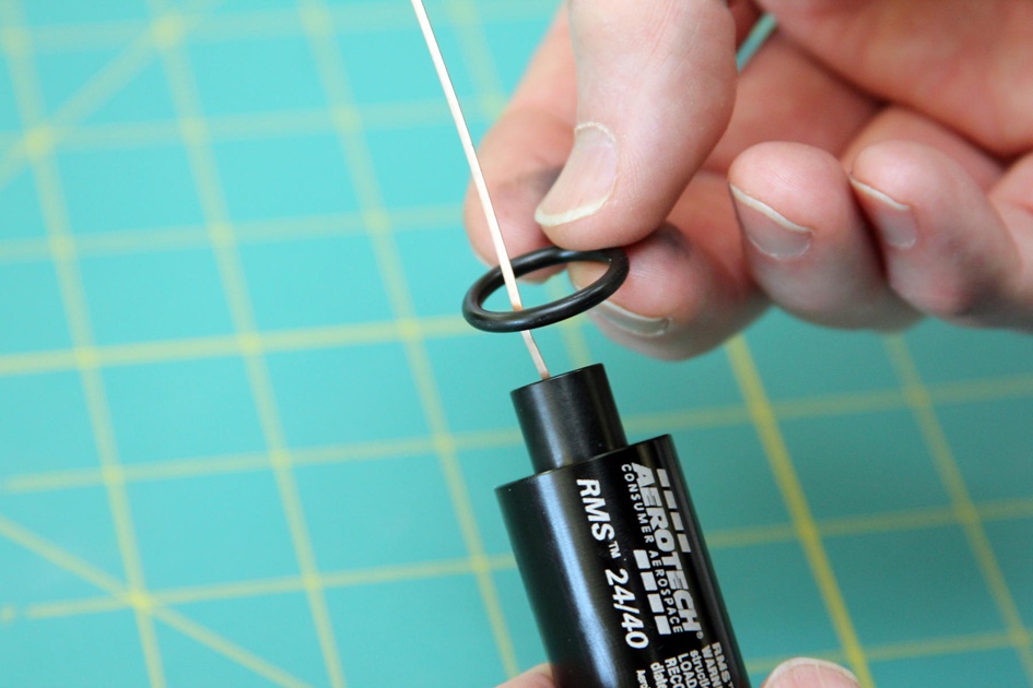
Slide the last O-ring over the igniter so it rests against the bottom of the nozzle.
Put a little grease on the threads of the aft closure if it is new, and then thread it into the base of the motor. Be careful, because the igniter can still fall out. You may need to apply a bit of force to tighten the closure all the way, but it should meet the motor tube. Don’t use tools to tighten it, though. A paper towel or rag will help; this keeps the sharp edges from the aft closure from pushing into your hand.

The black powder ejection charge is snuggled safely in the two overlapping red plastic caps. Hold the caps and carefully remove the larger one, leaving the black powder in the smaller cap. As you do this, take care not to spill any of the black powder.

Place the ejection charge cap onto a flat surface and press the forward closure into the cap. It will fit snugly, creating a seal that will hold the black powder in place until it fires. Turn the motor over and tap gently to get some of the black powder into the forward closure, resting right on top of the delay charge.

Use a hobby knife to cut a small slot in the closed end of the larger red cap. The hole should be large enough for the igniter.

Directions from the manufacturer show the Copperhead igniter bent over, with the cap holding the igniter in place on the side of the nozzle. I’ve tried this, and judging from discussions in rocketry forums, others have, too. This seems to lead to misfires. I don’t recommend installing a Copperhead igniter that way. Thread it through the hole you just cut, instead.
Slide the cap down and over the end of the nozzle. Depending on the size of the hole, the igniter may be loose enough to fall out. If it is, use a piece of tape to hold it in place.

This completes the motor assembly. As with any complicated task, it’s easy to miss something. Here’s a checklist for this specific motor that will help you assemble it correctly each time.
Attaching Igniter Clips to a Copperhead Igniter
We’ve assembled the motor, but there is still the issue of connecting the igniter clips to the igniter. There are two ways to do this. The first is to apply tape to one end of the igniter clip so the clip only makes contact with one side of the copper strip. While this works, it’s kind of obnoxious: the next person to use the igniter clip will need to remove your tape and clean your excess glue from the igniter clip.
The second way is shown in Figure 23-26. Put a piece of tape on each side of the copper lead, leaving some of the lead exposed on the back side of each piece of tape. Clip the leads to the igniter so one side of the clip touches the tape and the other touches one side of the igniter.
If you look at the clip, you’ll see that one side of the clip is soldered to the launch wire, while the other side is fastened to the clip with a metal bar and spring. Attach the clip so the side of the clip that is soldered to the wire touches the copper igniter lead, and the other side touches the tape. This helps a little by cutting the resistance to the lead slightly.
Attach the clips as close to the rocket nozzle as practical to reduce the overall resistance.

Cleaning the Motor
Single-use motors have a paper case that is a pretty good insulator. While they may be warm or even hot, it’s easy enough to pull them out of the rocket right after a flight. That’s not true with a reloadable motor. The metal case will be quite hot after the flight. Wait a few minutes before trying to remove the motor.
Once the motor cools enough to handle, it’s time to clean it. You might leave this job until you get back from the flying field, but don’t leave it for the next day. The longer you leave the motor before cleaning it, the harder it will be to clean. It’s just like washing the dishes—the longer you let the mess sit, the harder it gets. The burned fuel and ejection charge are also mildly corrosive, and can damage the motor if left too long.
I find it very strange that rocket supplies are frequently mislabeled and shelved in the oddest locations in stores. My personal favorite tool for cleaning reloadable motors is called “baby wipes,” and they are found in the grocery store where baby supplies are sold. They are perfectly designed for rocketeers who need a convenient package that will travel well, be easy to open, and seal easily to keep the content moist. I suppose they are convenient for wiping babies, too. An alternative to baby wipes is rubbing alcohol and paper towels. A pencil or dowel is handy for pushing out the motor liner, and needle-nose pliers can be useful for pulling out stubborn delay charge liners.

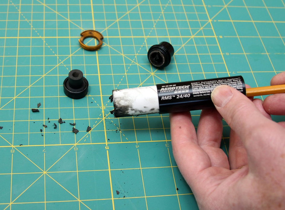
Begin by removing the forward and aft closures. Pull out the nozzle and dispose of it. Use a pencil, a dowel, or your finger to push the motor liner and any remaining O-rings out of the motor case. Dispose of the O-rings, motor liner, and any ashes from the spent fuel. These are safe to throw out with the normal garbage.
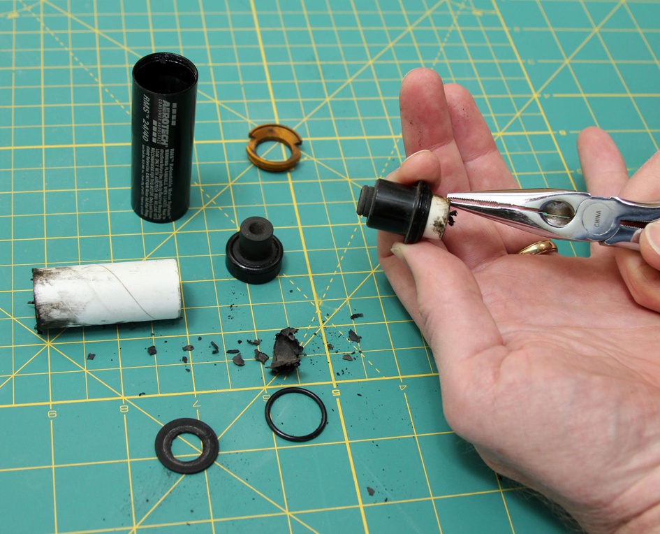
Remove the delay charge liner and O-ring from the forward closure. This is usually pretty easy to do, but if it is stuck, try gripping the end of the liner with needle-nose pliers. You may also need to pry out the O-ring that was in front of the delay charge liner. Use something soft, like a toothpick. Never use sharp implements like a hobby knife, which might slip and score the metal.
Dispose of everything you remove.
Use a baby wipe or a paper towel soaked in rubbing alcohol to clean the inside and outside of the motor tube, forward closure, and aft closure. Take your time, wiping all surfaces until they are perfectly clean. Be sure to clean the threads. One way to do this is to fold the wipe over your fingernail and scrape the inside of the threads with your nail. When you finish, all surfaces should be as clean as new.


Once all parts are clean, wipe some grease on the threads and replace the forward and aft closures. The motor is ready for storage and for reloading just before the next flight.
You might want to use the same motor several times in a day. While I prefer to build motors and clean them at home, it’s perfectly reasonable to clean and rebuild a motor at the flying field, too. Just be sure to bring along a trash bag and all of the cleaning supplies.
Designing Your Own Rockets
This book gives you all the basic tools you need to design and build model rockets that use 40 N-s of total impulse or less—an E motor or smaller, or a combination of motors with a combined total impulse below that level. You’ve seen how to build rockets of all sizes and descriptions, from tiny sport rockets like Eros, which flies on an Estes T motor, to big, impressive rockets using multiple motors, either for staging or for clustering. You learned all sorts of recovery methods, from parachute to glider. You also learned a lot about how to select parachute sizes, how to design fins, how to reduce drag, and how to select an appropriate motor for a rocket. That’s a lot of information. Some of it is critical, and some of it is just there to give you a deeper understanding of rocketry.
The only way to make sure you’ve really grasped all of the important information is to put it to use. That’s what we’re about to do. The last project in the book is to design and build your own rocket. We’ll use this project to organize the information in the book, making sure you can put all that theory and construction experience to good use by building your own rockets.
The project I’m going to suggest is a rugged and powerful sport rocket, capable of using either disposable D and E motors like those sold by Estes, or reloadable D and E motors like those sold by Aerotech. It will essentially be a scaled-up version of Juno that can take the larger motors. As with Juno, you’ll be able to add a payload bay later, as long as the body tube size is not larger than the size you select for the rocket.
Of course, you don’t have to build the rocket I’ll describe. Maybe you’re on a TARC team, and you’ve been reading this book to figure out how to build a winning rocket. Or perhaps you have a small camera you would like to fly to photograph your school or house. Whatever project you choose, you can follow the steps we’ll go through to design and build a successful model rocket.
Collecting the Requirements
Every successful engineering project begins with a requirements phase. This can be very formal or very simple, depending on how many people are involved. For a model rocket, this means deciding what the rocket will do, what size motor it will use, and what recovery system it will use. If the goal is to break your club’s altitude record for a C motor, you’ll be building a minimum-diameter rocket with the thinnest possible fins. You will need to decide on the shape and size of the fins, as well as whether they will be sanded to an airfoil. You will need to pick the shortest body tube that will give you a stable design, trading off between fin size and body tube length to minimize drag while maintaining stability.
If there is more than one person involved, it’s also convenient to pick a name early in the design phase so you have something to call the project. All of the other solid propellant rockets in this book have been named for asteroids. This one is beyond the scope of the predesigned rockets in the book, so let’s reach a bit further and call this one Eris, after the largest known trans-Neptunian minor planet.
Eris will be a sport rocket that will use D or E motors, which are 24 mm in diameter. These fit nicely in a BT-50 body tube. Since this is a rugged rocket, we’ll use a BT-55 body tube for the airframe. The rocket will use parachute recovery. Eris is a bigger version of Juno.
One nice thing about the choice of a BT-55 body tube (for those who have been following along, building the rockets in this book from the Estes Designer’s Special) is that you have a leftover BT-55 body tube and nose cone. Reusing available parts is a great way to keep a project’s budget under control. It’s a technique NASA and other large players use. NASA’s Mercury-Redstone, Mercury-Atlas, and Gemini-Titan all used recycled military missiles for their boosters. Even the Saturn IB used recycled motors and tanks from earlier rockets.
Initial Design
With the requirements in place, it’s time to lay out an initial design for the rocket. This means picking a body tube length and nose cone; deciding on the number, size, and shape of the fins; and selecting an initial parachute size. The best way to do this is to create the design in a rocket simulator. Both RockSim and OpenRocket have design tools that help you quickly create a rocket design. You’ll need to simulate the design to make sure it is stable anyway, so why not set up the design in the simulator right away?
You’ve seen rocket simulators before, in Chapter 7 and Chapter 14. You should find it pretty easy to crank up OpenRocket or another simulator and put the rocket together. I want to make sure you know how to design the rocket, but I don’t want to design it for you. Instead, I’ll show you how to use OpenRocket to design a rocket like Eris from scratch.
Sizes in OpenRocket are given in centimeters by default. You might want to switch the units to inches in the preferences dialog. That will also make it easier to follow along with this example, which shows all measurements in inches.

OpenRocket starts with a window for a new rocket. The first step is to add the various components that make up the airframe. Working from left to right in the components area, we start with a nose cone. Clicking the nose cone icon opens a dialog that shows the design parameters for this component (Figure 23-33).
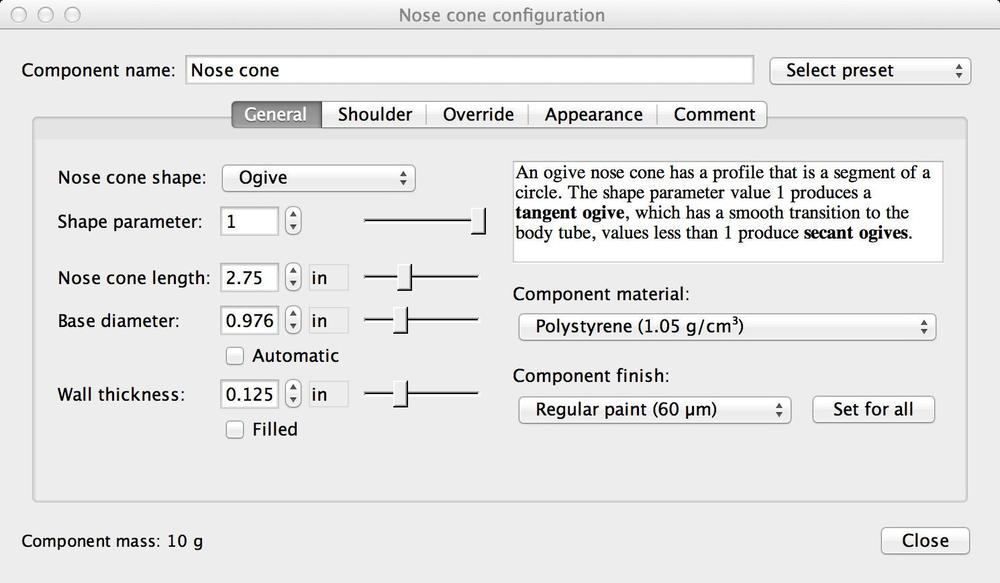
Fill in the values for the nose cone you have selected. There are two parts to a nose cone, the tip and shoulder. The General tab we started on only includes the tip. Click on the Shoulder tab, shown in Figure 23-34, and fill in the appropriate values for the shoulder. So what are the appropriate values? One way to find out is to measure the nose cone. You might also find dimensions on the manufacturer’s website.

Close the nose cone dialog and click on the body tube icon to add a body tube to the rocket. This opens a dialog where you can enter the size of the body tube (Figure 23-35). You can find common body tube sizes back in Table 3-4 from Chapter 3. Manufacturers will also provide details on the sizes and materials of their body tubes, so you can check the manufacturer’s website for less common body tube sizes. Fill in the values for your rocket and close the dialog.

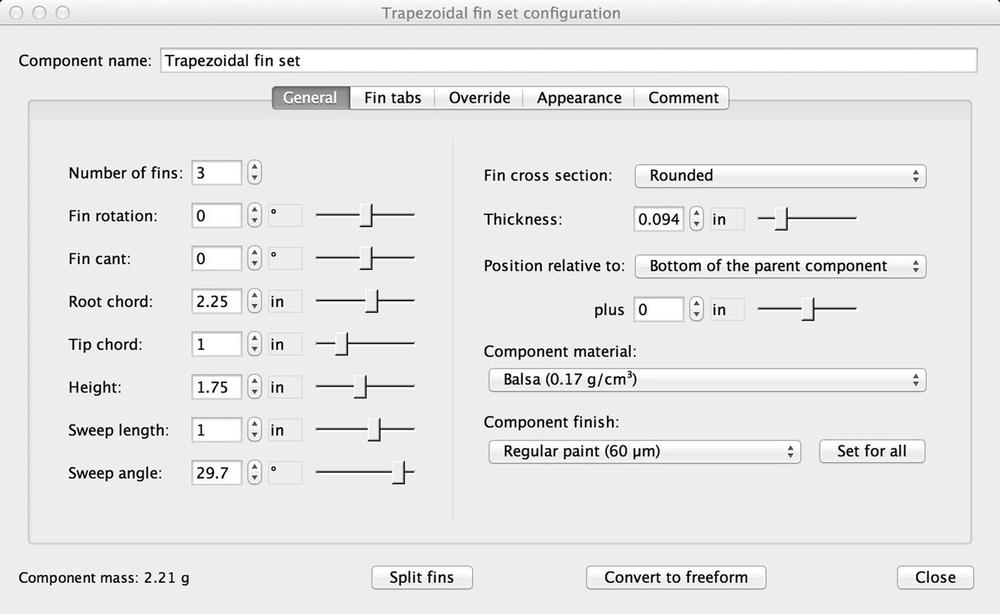
Fins are next. You want to add the fins to the body tube, not the nose cone, so be sure and select the body tube by clicking on it in either the list of components or the image. Then click on the fin icon that matches the shape you’ve selected and fill in the values for your rocket in the resulting dialog (Figure 23-36). Don’t forget the values on the right. You need to select the proper fin material, fin cross section, thickness, and finish, too.
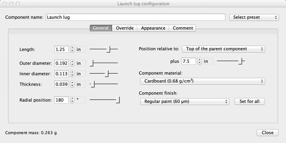
Follow the same pattern to fill in the details for the launch lug (Figure 23-37). Again, the launch lug is attached to the body tube, so be sure to select the body tube by clicking on it before clicking on the icon for the launch lug.
With the outside of the rocket complete, it’s time to turn our attention to the interior. Select the body tube, and then click on the inner tube icon.
There are two tabs where values need to be set, and a few others you may want to look through for other options. The first is the General tab, where you set the tube size and length (Figure 23-38).

This tube will be used as a motor mount, so click on the Motor tab (Figure 23-39) and select the checkbox indicating that this is a motor mount. The motor on Juno is also designed to hang 1/4” out of the rear of the rocket, so the motor overhang value needs to be set to 0.25”.

The motor mount is held in place with centering rings. Close the motor mount dialog, select the body tube again, and then add a centering ring. Fill in the values as shown in Figure 23-40. The outer and inner diameter will be filled in automatically when the centering ring is positioned properly. Add a second centering ring near the other end of the motor mount.

Sometimes your rocket will have a component that isn’t on the list of components. These components still matter, since their mass affects both the center of gravity and the overall mass of the rocket. The engine hook is a good example. We add these components as mass objects—things that have a general shape and mass, but otherwise have no impact on the rocket simulation.
Figure 23-41 shows how to configure a mass component for the engine hook. The specific size is not all that important, as long as the overall mass and the location of the center of mass are reasonably accurate. It might be tough to find the mass of a component, though, especially a light one. You may find the mass on a manufacturer’s website, but how can you accurately measure the mass of something like an engine hook that is very light, when typical scales may only measure to the closest gram? One way is to weigh 10 or so of the objects at once and divide the overall weight by the number of objects.

Follow the same pattern to add a parachute and shock cord to the body tube, as seen in Figures 23-42 and 23-43. While they tend to be near the nose cone when packed, I have always suspected they slide down toward the motor when the motor fires. Putting the mass of the parachute and shock cord lower in the rocket is the conservative choice, so that’s where I put them.
If the rocket is stable with the parachute near the motor, it will still be stable if the parachute actually stays near the nose cone, since shifting the center of gravity forward makes the rocket more stable.


Simulating the Rocket
The reason for designing the rocket in OpenRocket was to make it easier to run the simulation. At this point you should check the performance of the rocket. Of course, you need to select a motor, and the weight and power of the motor could affect whether the rocket is stable. What if you want to use A motors, but they are not powerful enough to lift the rocket off the pad quickly enough? Or what if you want to use a C motor, but the weight of the C motor makes the rocket unstable? I’ve seen both of these situations with rockets. A common engineering practice in this situation is to bracket the problem. The simulation needs to be done with two motors: the least powerful you intend to use and the heaviest you intend to use. For Eris, this means Estes D and E motors.
We covered how to check the center of gravity back in Chapter 7. Once the motor is loaded into the simulation, it’s right there on the main screen, above and to the right of the rocket, as seen in Figure 23-44. The rocket will be stable as long as the Stability factor is at least 1. A value of 1 to 2 is ideal. While values over 2 are acceptable, they indicate an overstable rocket that might have trouble in high wind. Check for stability with the heaviest motor. If that one works, lighter motors will, too.
You will need to make design changes if the rocket is not stable. You can make the fins larger, add more fins, or move them further toward the rear of the rocket, perhaps by using swept fins. You can also make the body tube longer, moving the center of gravity toward the nose of the rocket. Another alternative is to add weight to the nose.
The ground hit velocity tells you how fast the rocket will be traveling when it hits the ground, which tells you if the parachute size is appropriate. When you bracket engines, this value won’t change much unless the motor sizes are dramatically different, such as changing from a 2 3/4"-long D motor to a 3 3/4"-long E motor, or unless the payload weight changes. The landing speed should be between 3.5 m/s and 4.5 m/s. Try a larger or smaller parachute if the speed is well outside this range. Select the parachute that gives a landing speed closest to this range.

The remaining two values change a lot from motor to motor, so you need to check them for each motor you plan to use in the rocket. The first is velocity off of the rod. As you know from Chapter 7, the rocket should be traveling at 30 mph, or about 13.4 m/s, when it leaves the rod. Rockets sometimes fly successfully coming off the rod a bit slower, but it is best to stick with this speed or a higher speed whenever possible. If the rocket is not leaving the launch rod at an appropriate speed, you will need to either reduce the weight of the rocket, lengthen the launch rod, or increase the initial thrust of the rocket.
The last thing to check is the velocity at deployment. This is the speed the rocket is traveling when the parachute opens. The best way to check this value is to try all of the available delay times for a particular motor. Choose the one with the lowest speed at ejection. If two ejection charges have values for speed at deployment that are close, it is likely that the rocket is traveling up when the ejection charge fires for the shorter delay, and down for the longer delay. In that case, you will generally pick the longer delay time to allow the rocket to reach the maximum possible altitude.
Not all simulators do this, but OpenRocket has another nice feature. There is a colored dot to the left of each simulation. This indicates if OpenRocket found any issues. It will, for example, turn red if the rocket is not stable. As engineers, we should always check the values ourselves, but it’s nice to have the software double-check our results.
Construction
Once the design is complete, it’s time to build the rocket. You’re well prepared to build it after reading this book and building a few of the rockets.
Once you have assembled the rocket, double-check the simulation results for center of gravity. If you can, check the overall mass, too. You can check the mass on a kitchen or school laboratory scale. It’s easy to check the location of the center of gravity by installing the parachute and motor, then balancing the rocket on your finger. You can change the simulation if the measured values are significantly different from the simulated values, and then rerun the simulations to make sure the rocket will fly safely.
Flight Testing
Simulations have their place, but you should always test the rocket in flight. The general practice is to fly the rocket on the smallest possible motor for the first flight. That way, if there are any mistakes in the design or the build, they’re not amplified by the power of a large motor! It’s also important to test the rocket with the heaviest motor to check its stability.
Test flights should be done with the smallest possible crowd. You should make sure all of the spectators are aware the launch is a test flight, and make sure they are all standing, facing the rocket, and paying attention when it is launched. At our club launches, the LCO yells “Heads up!” for any test launch so people are aware they should pay closer than normal attention.
If you’ve done everything carefully up to this point, pushing the launch button should just confirm your engineering skills with a flawless flight. On the occasions when that doesn’t happen, take the time to identify the cause of the failure. Decide right away what you will do differently in the future to prevent the same failure. Everyone makes mistakes, and everyone has failures. The mark of a good engineer is learning from those mistakes so they don’t happen again. The mark of a great engineer is carefully following accepted practice and watching other people’s mistakes so very few mistakes are made in the first place.
Odd Rockets
Up to this point, all of the rockets in this book have been relatively normal, and each has had a purpose. They were carefully chosen to teach some aspect of rocketry, demonstrating unique recovery methods, different kinds of payloads, or how small or large model rockets can be.
Enough with normal—let’s have some fun!
Odd rockets, sometimes called oddrocs, are rockets that don’t look like rockets at all. You can make anything fly if you have enough power, and if the center of gravity is far enough ahead of the center of pressure. One example is a Styrofoam Easter egg. Drill it out for a motor and launch lug and add some 18"-long dowels, and it flies quite nicely. The rocket is very light once the motor pops out, so featherweight recovery works well. You can come up with lots of holiday or other unusually themed rockets.

Fins come in all sorts of odd configurations. A favorite at many launches is called a tube rocket, where a cluster of body tubes replaces the traditional fin. Be a bit careful when designing these rockets, though. The tubes add a significant amount of weight to the rear of the rocket. You don’t want to make the fin tubes very long, as that would move the center of gravity back far enough to make the rocket unstable.

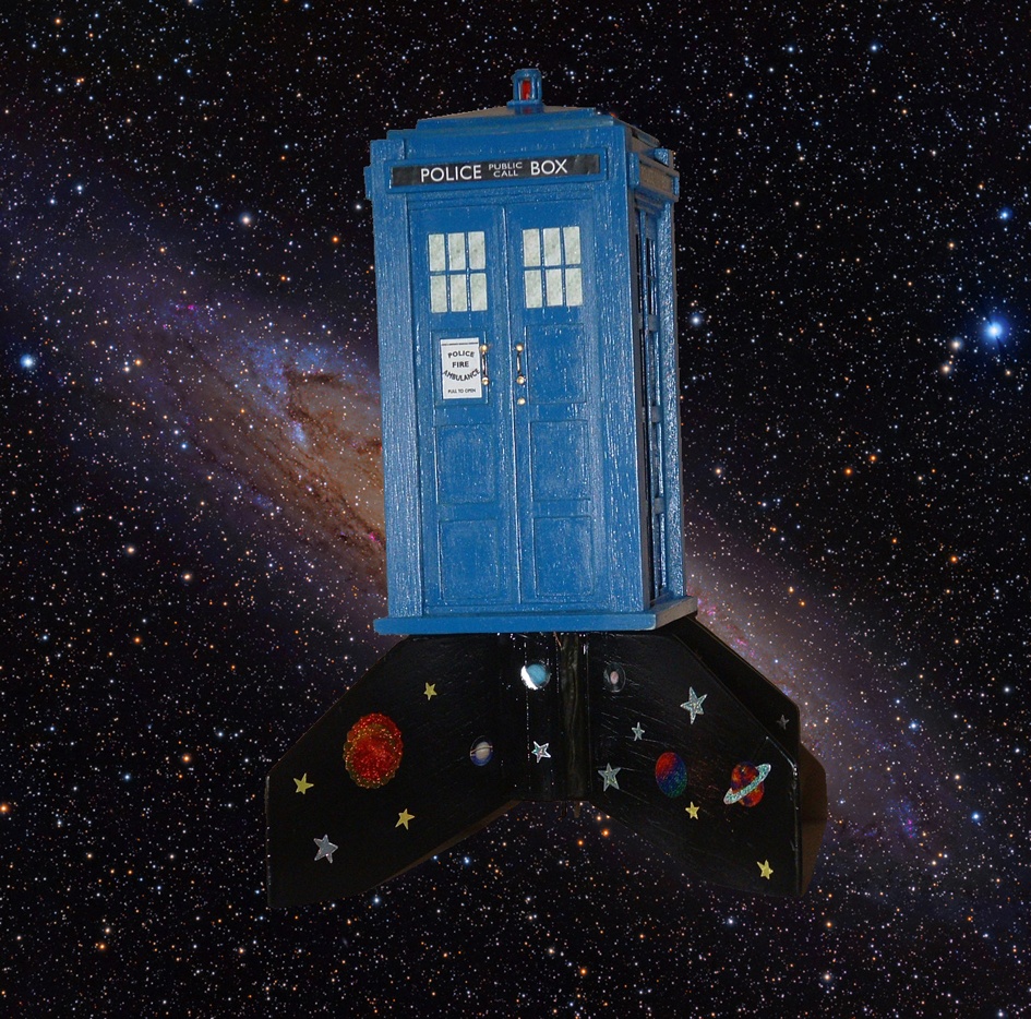
When I said you could make anything fly with enough power and an appropriate choice of centers of gravity and pressure, I meant that literally. Figure 23-47 shows a great example—it’s a flying Tardis, paying homage to the Dr. Who TV series.
Some model rockets aren’t that odd, but they are very cool. Scale rockets fall into that category. Researching a rocket to build a good scale kit is a great way to learn about the history of space flight, as well as technical aspects of aerodynamics and astrodynamics. Figure 23-48 shows a rocket that is both an odd rocket and a scale model—it’s a scale model of the very first liquid-propelled rocket ever built. Robert Goddard flew the original on March 16, 1926. This rocket is a kit produced by FlisKits.

Finally, let’s take a look at an odd use for an otherwise normal rocket. Figure 23-49 shows the garter toss at the wedding of Steve and Susan Foy. The rocket is painted like a tuxedo, and carried the garter! A second rocket, white with silver lace, carried a part of the bouquet for the bouquet toss. It was quite a sight seeing guys in tuxedos and women in dresses vaulting fences to chase down the rockets!

The Outer Limits
Rocketry can take you in many different directions. One person in our club is really good at photography from rockets. Another is an expert on the V2. Another has published papers on supersonic flight based on high-power rockets that fly at around Mach 3.5.
Whether rocketry takes you in one of these directions or somewhere totally different, I wish you the best in your experiences.