INTRODUCTION
In Chapter 2, I provided a summary overview of the types of kits available today and the relative merits of each type of kit in terms of material types, degree of accuracy and limitations. In this chapter I will cover the construction of wagon and van kits as a prelude to kit conversions and scratch building rolling stock, which I will cover in more detail later. I also provide a brief overview of the range of kits on offer and specifically consider the varying skill levels required to complete them.
I have used worked examples to show the techniques and issues that a modeller should bear in mind when constructing different types of kits – from basic to specialized.
Before looking at the way these kits are put together, it is useful to cover some basic principles that apply no matter how simple, or complicated, the kit.
STARTING WITH THE INSTRUCTIONS
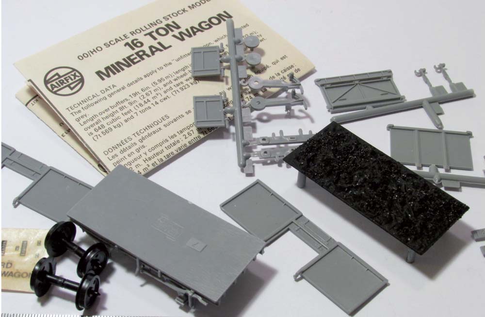
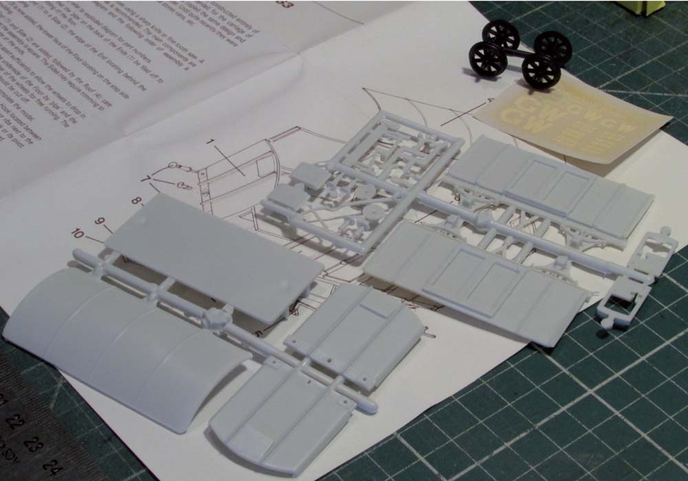
The most important part of building any kit is to read the instructions all the way through before starting anything. This will help you to get a picture in your mind of how the wagon or van is going to materialize from the collection of parts sitting in front of you on the workbench or table, as shown in Figs 29 and 30. In the case of most, but not all, models there will also be a series of sketches or drawings provided with the kit, illustrating the key stages of the construction process, showing how and where parts fit together. This, unfortunately, is not always to the same standard and on some kits you may only get a list of instructions, or construction steps, whilst sometimes you may be lucky and get an exploded diagram of part or all of the model and a picture of what the finished article should look like when you have toiled away at it for a few hours or days. In these circumstances, photographs of the prototype are even more important; the photographs will help to clarify what needs to go where on the model, especially if the model is of a prototype where there may have been numerous changes or adaptations over the operating life.
Fig. 29 Laying out the parts of the model on the workbench before you start building enables you to look through the instructions and familiarize yourself with all the parts.
Fig. 30 In the case of the Airfix Models BR Mineral open wagon kit, the instructions provided are clear and easy to understand.
Some kits are provided with only a very limited set of instructions and possibly an exploded diagram, from which the modeller is supposed to build the kit. These types of kits in the main are aimed at the more experienced modeller, who will probably have a good idea of what the wagon or van is going to look like before starting the model kit.
FIRST STEPS
Dry runs of some stages of the kit construction are a useful exercise in not just giving you an understanding of how things fit together before you fix them permanently, but also it is a way of checking that you have all the appropriate parts and that nothing is missing. There is nothing more infuriating when modelling than working through a kit only to get stumped when you cannot find the next piece because it has been mislaid or even lost.
As a tip, I always keep all the pieces for any kit that I am working on either in a re-sealable bag or plastic box with a lid, to ensure that nothing gets lost. The box can also be used to collect together all the additional detailing parts that I will need for the wagon or van, before starting to build the kit, again to make sure that I do not need to order or buy something part way through a project. This I find is a good way of checking I have everything and a good way of stock-taking components that I can then replenish in good time before starting something new.
As with most things in life, the quality of the product, i.e. the finished kit, is directly proportional to the amount of time that you spend making it. If you rush through the kit, sticking things together, without cleaning off joints or checking with dry runs to ensure that they fit together correctly, or not waiting until joints have hardened off, for example, you will likely end up with a van or wagon that will not look right, invariably will not run smoothly and, worst of all, may end up breaking or falling apart and need re-building. This could result in the kit being completely ruined, which would be a waste of time, effort and money if you have to scrap something and start all over again. In these times of austerity, I am sure that unless you are financially flush with funds for your hobby, having to ‘buy that expensive kit again’ won’t go down well with the domestic financial director.
The trick is to learn to be patient. I have been guilty of rushing things in the past and learnt the subsequent lessons; I now try to be patient and leave things to harden off or dry for several days between key stages of the construction process. Some of this is driven by the need to carry out other things around the home or even work (!), but the results are obvious to me in the production of better models, which I hope you will agree from the photographs of the rolling stock that I have made that have been included in this book.
PREPARATORY WORK
As part of the process of building a kit, you also need to think before you start about how you are going to finish it off with painting and decals, and to a lesser degree, where preferred, the application of weathering. During the construction process, or even before, it is often better and easier to paint all, or at least some, sections or key parts before fixing together; whilst for other parts it is better to paint after construction has been completed; for example, the overall body after you have formed the corner joints.
Preparing kits or parts of kits before construction is also a vital part of the kit building process. Fettling, as it is often referred to, is the process of cleaning away any flash or imperfections in the kit parts that may have been produced during the kit moulding process. This only really applies to kits or parts made from white metal, plastic or resin that have been cast or moulded. Brass kits tend to be etched frets, with only minor cleaning up of the burrs where parts are removed from the fret required as part of the preparation process.
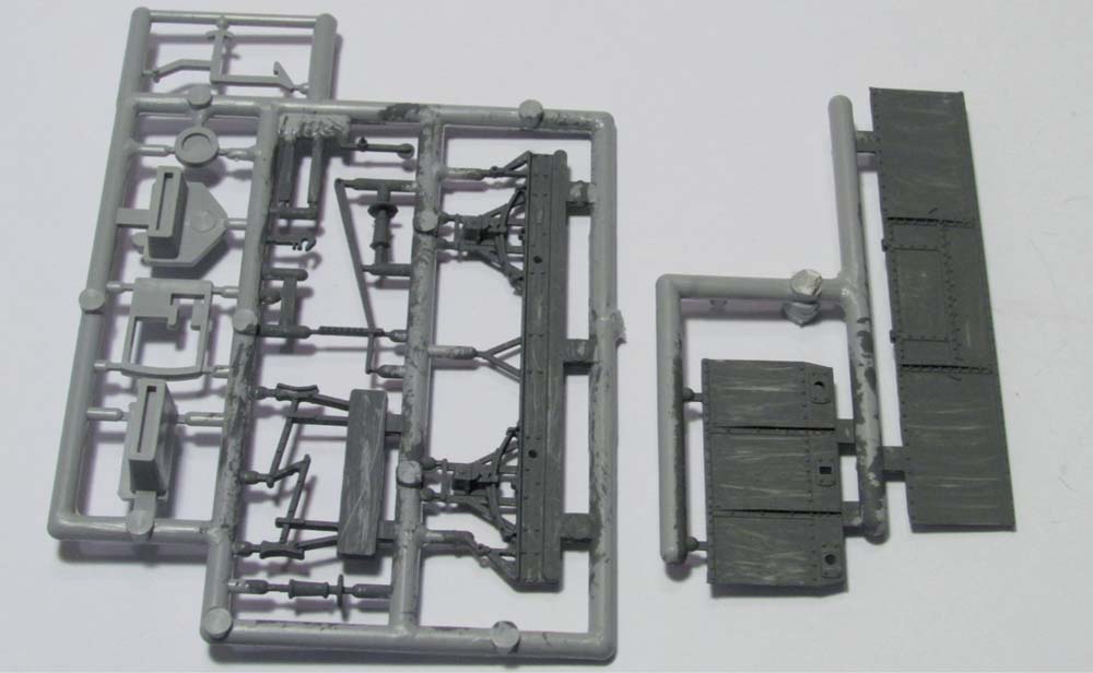
Fig. 31 It is often helpful to pre-paint some or all of the parts of kit prior to removal from the sprues for construction.
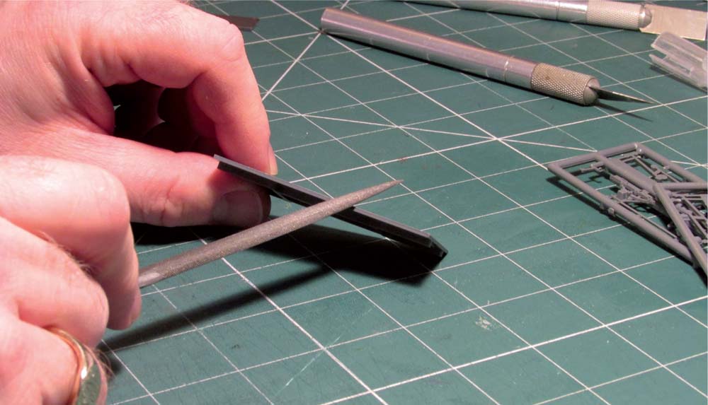
Fig. 32 After removing the parts from the sprues using a craft knife, razor saw or side cutters, fine filing adjustments to parts should be carefully undertaken with a fine file.
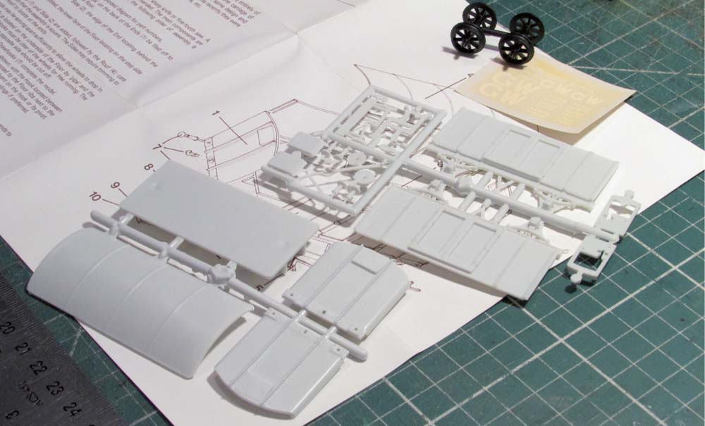
Fig. 33 Example of a Ratio van kit parts and instruction sheet removed from the packaging and laid out for inspection.
It is important also to bear in mind that as a result of the casting process for white metal and etching of brass, the metal will need cleaning and de-greasing to get rid of the compounds used in the production process that coat the metal, before priming and painting the metal parts.
CONSTRUCTING A BASIC KIT
To provide some guidance and advice on the construction of straightforward or simple rolling stock kits, I will describe the process from opening the box to completing the decals and running on the layout. Along the way I will explain how to overcome common problems and will provide tips to help the beginner through the process. For the basis of this exercise, I have assumed a complete beginner is approaching the construction of a piece of rolling stock for the first time.
In Chapter 2, I went through the process of identifying what tools might be needed, and in the earlier part of this chapter I discussed some of the preparatory activities that are required before starting to build a kit; now it is time to have a go at building something.
BUILDING A VAN KIT
For the purposes of this example, I chose an old Ratio Iron Mink kit (Ratio ref: 5063, newer models Ratio ref: 563) that I had in my box of kits waiting to be made. The first part of the process is to open the box containing the kit and carefully remove the parts, some if not all of which may be attached to sprues, and lay the parts on the working surface. For the Iron Mink kit, it is apparent at first glance that this kit comprises six main parts, plus some detail components and a set of plastic wheels.
The instructions are typical of this type of kit, comprising a single-sided sheet with written instructions and an exploded diagram of how all the parts go together. To provide further information as to what the finished wagon should look like, reference to a photograph of the prototype would be useful and for those looking at Great Western railway wagons, the invaluable reference sources provided by Russell (1971) and Atkins et al. (2013) are highly recommended.
After reading all of the instructions and reviewing the drawing, the first step is to remove the parts in the sequence suggested in the assembly instructions. As a tip, do not remove smaller parts from the sprues until required for assembly, as they are likely to get lost or broken. For this type of kit, painting can easily be left until the kit has been constructed, as there are no difficult-to-access parts or fine detail parts requiring pre-construction painting.
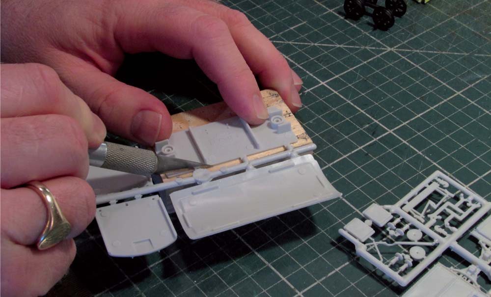
Fig. 34 When removing parts from the sprue, it is recommended that the parts be supported using one of the blocks of wood that you have collected for your model making.
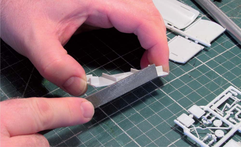
Fig. 35 Cleaning up the cut marks and removing unwanted materials from the moulding process, referred to as flash, can be completed with needle files.
When removing the parts from the moulding sprues, it is advisable to use a sharp craft knife and support the part and sprue connection on a piece of wood to prevent damage to, or deformation of, the part during removal, as shown in Fig. 34. Alternatively it is possible to use specialist sprue cutters. However, in either case, the use of fine files will be necessary to remove flash and unwanted material at the sprue connection, as shown in Fig. 35.
When using files to tidy up the parts, do this carefully and a small bit at a time to avoid damage. It is also helpful to check the part against the photographs of the prototype to ensure that the model will look correct, whilst you are carrying out the fettling. When you are happy with the fettling of the parts, do a dry run of the assembly stage to check that the parts fit together correctly. If necessary carry out further fine adjustments with fine files or glass paper, again going through this process a small bit at a time to avoid damaging the model.
Fig. 36 All the main parts have been removed and prepared for dry run assembly before construction.
After the dry run of one end and one sidewall, it will be necessary to check that the floor fits correctly before the side and end walls are fixed together. In the case of the Iron Mink van kit, the instructions indicate that the moulding pips on the inside face of the walls need to be filed flat, to ensure a snug fit of the floor with the end wall. This needs to be done before fixing any of the parts together.
At this stage you also need to decide whether you plan to use the buffers and coupling hook details for the buffer beam as supplied in the kit, or whether you want to replace them with alternative detail parts. In Chapter 4, we will look at using alternative components to details of wagons and vans, and the installation of these will be discussed further there. Assuming that you wish to proceed with the buffers and coupling hook as supplied in the kit, these parts need to be carefully removed from the sprue and inserted into the holes provided on the buffer beam, which is integral to the end walls on this kit.
The buffers and coupling hooks are small and extremely fragile parts that can easily be damaged or lost when removing from the sprue. To do this carefully I find the best solution is to support the sprue and part on a piece of wood and whilst cutting the part free, place one of your fingers on the part to gently hold it in place so that it does not twist, break or fly off to disappear somewhere on the floor.
Checking the fit of the buffers and coupling hook in the pre-drilled holes in the buffer beams is carried out before fixing permanently with drops of liquid polystyrene cement. When the parts have set, the kit can then be constructed following the steps and drawings in the assembly instructions for guidance. To get the best results do not rush, and use liquid polystyrene cement applied either with the fine needle applicator or a brush. Using small spots of adhesive, bring the joints together and check to ensure that the joint is square, then apply a further thin stream of adhesive to the inside of the joint to strengthen and reinforce the joint.
This particular kit goes together easily and quickly after all the preparatory work I have described and the final shape of the wagon soon becomes apparent. When both sides of the wagon have been fixed together, it is advisable to check that it is square by using a flat glass tile on which to sit the model. At this stage it is also a good idea to spring open the axle boxes and drop in the wheel sets to check alignment and that the wheels are running freely in the axle boxes. Set the model aside to dry if all is well.
Whilst the body of the kit is drying, take the roof and remove from the sprue. The edges of the roof will require fine fettling with glass paper and fine files to remove flash and to ensure that it is ready to fix to the body.
The brake gear and brake lever can be removed from the sprue and checked for fitting to the model. The brake gear on the Iron Mink van only fits on one side, indicated by the locating pips on the underside of the wagon floor. With the wheels in place, check the fit of the brake gear and adjust as necessary with a fine file to ensure a snug fit. It is important that the brake shoes are in line with the wheel treads, but do not impede the free movement of the wheels, as shown in Fig. 38. When you are happy with the fit, fix in place with adhesive. Reference to prototype photographs comes in useful at this point, as the fitting of brake gear to many wagons and vans varies considerably, with similar vehicles fitted with brake gear on one or both sides.
Fig. 37 When the sole bars have been fixed to the body, the wheels should be installed to check accuracy and that they are free-running.
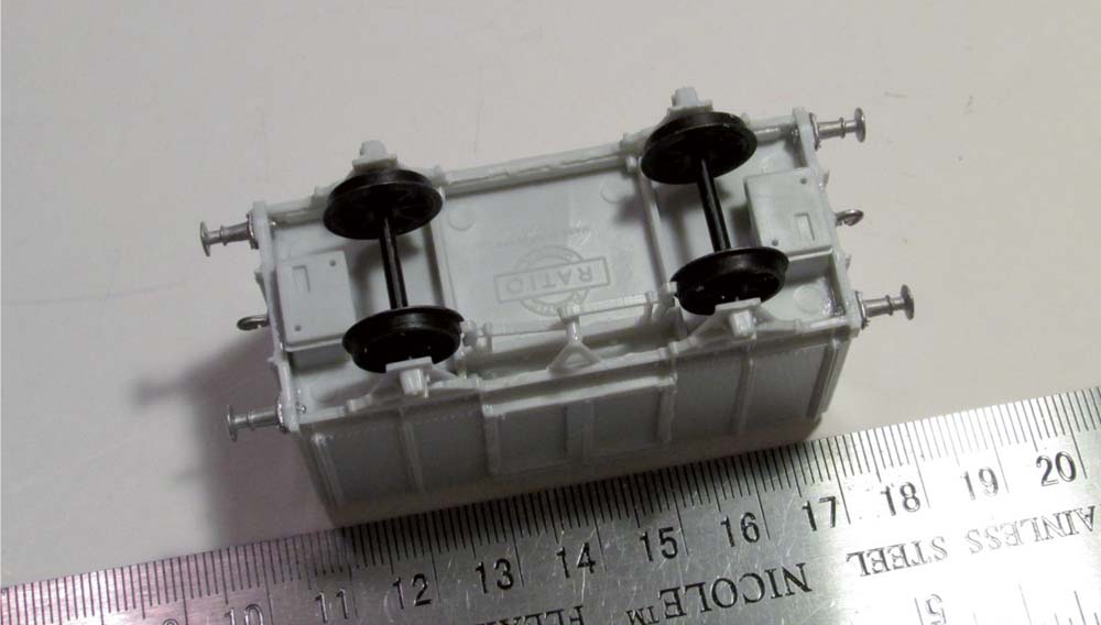
Fig. 38 Underside view of the van kit during construction to show the addition of brake gear, which is carefully aligned to ensure that the brake shoes are in line with the wheel treads.
The brake lever fits at one end to the ‘V’ hanger on the sole bar and at the other end to the sole bar above the axle box. A trial run shows that these fixing points require the lever to arch between the two points. This lever is a fine detail part that can easily break, so to fix this without breaking I recommend that you first glue the joint and fix to the ‘V’ hanger and let it harden off for a couple of hours. Once dried, apply a spot of glue to the sole bar fixing point and gently push the lever into position; hold in place by hand or with a weight and let the glue harden off before removing.
To provide some additional ballast to the model, fix a steel weight to the floor inside the van. The weight should be placed centrally on the floor and held in place with contact adhesive. The amount of ballast to be added is down to personal preference, but I like to add some to all wagons and vans that I build, as it improves the track adhesion and thus the running qualities of the finished model. Do not overdo the ballast, as your locomotive might begin to struggle with a train load of heavily ballasted wagons to move.
The type of coupling to be used also depends on your personal preference. The tension lock coupling supplied with the kit is quite large. It is perfectly possible to use three-link couplings, utilizing the hole for the dummy coupling hook. I use tension lock couplings on my layout, so I complete the kit accordingly, except that I replace the supplied coupling with a smaller Bachmann mini-coupling (Bachmann ref: 36-025) as this is less obtrusive.
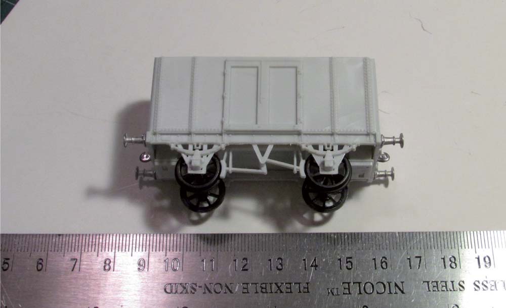
Once all the body has dried, and before fixing the roof, the body and underframe can be painted all over GWR freight wagon grey, as shown in Fig. 39. Wheel sets should be removed during painting and it is important to take care not to get any paint in the axle box bearings, as this will affect the smooth running of the wheels. The roof should be painted white if representing a newly out-shopped wagon, or can be painted white then weathered grey to represent a wagon that has been in service. When the paint is dry the roof can be fixed to the body, although I tend to fix the roof and body together after I have applied the decals, as it makes it easier to hold the wagon before the roof is fixed in place.
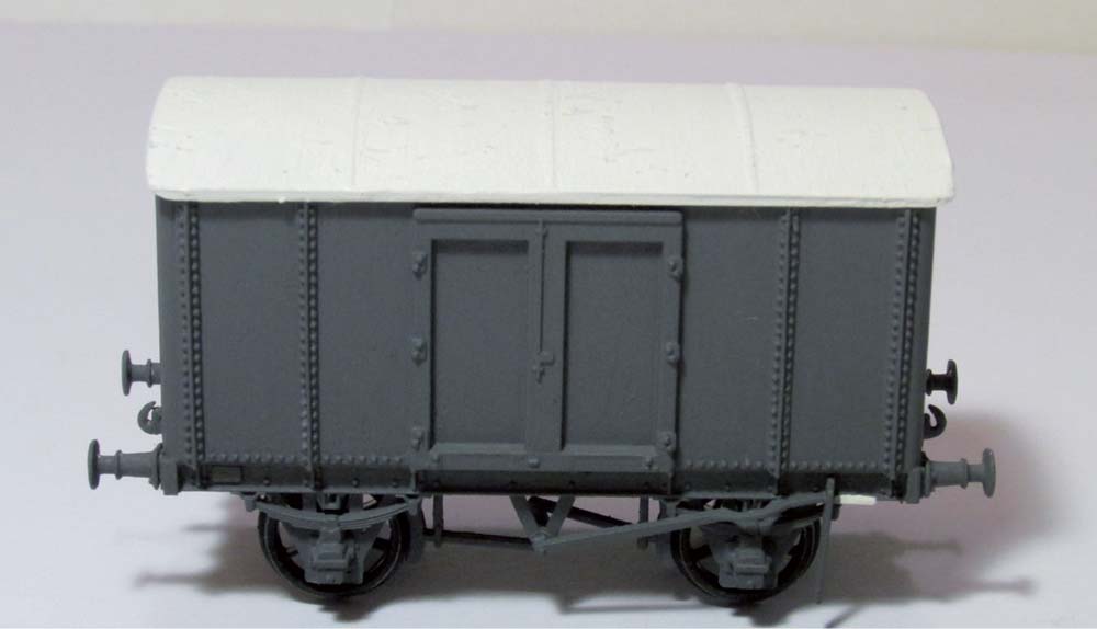
Fig. 39 On completion of the assembly, the body work has been painted in the appropriate railway company colours and the roof placed loosely on the body to check alignment and fitting.
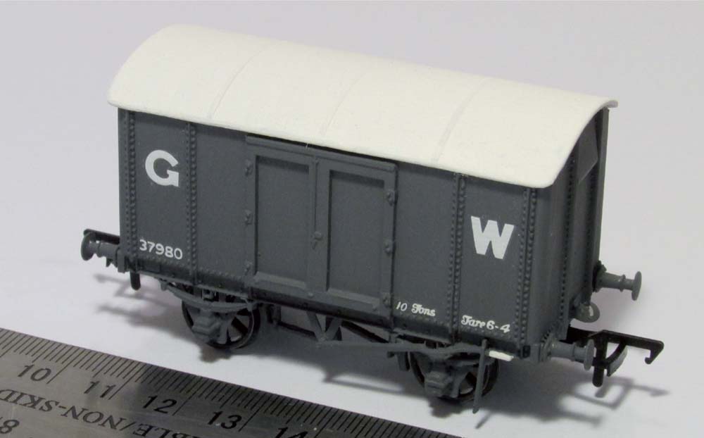
Fig. 40 When the painting has been completed and allowed to dry, the final detail to be added to bring the kit alive as a piece of model rolling stock is the addition of decals and couplings.
Fig. 41 The completed Ratio kit of the GWR Iron Mink van makes a nice addition to the rolling stock fleet.
The completed model is now ready-to-run on your layout. This type of kit can be built and finished quite quickly: typically, after preparation, all the fixing and modifying can be completed in a couple of hours, with painting and decals application to finish. However, do not rush; let the adhesives dry thoroughly for at least twenty-four hours before starting any of the painting. Let the paint dry (two coats may be required) at least twenty-four hours between coats before adding the decals. The result is a nice, well-built, neat model, which will look good on your layout and which you know you have built, rather than just lifted it out of a box – a very satisfying feeling.
CONSTRUCTING AN OPEN WAGON KIT
Constructing a basic open wagon kit is not too dissimilar to the method for a van kit, as described in the previous section, except that there is a need to paint the inside of the completed model and that you need to be aware that mistakes made during construction cannot be hidden under a roof! In addition, you will probably need to consider fabricating a load for the wagon, unless you wish to run it empty.
For this example, I used a Cooper Craft coal wagon (Cooper Craft ref: 1002), to which I added metal fine-scale wheels (Gibson 12mm diameter, eight-spoke) with brass bearings and white metal buffers (ABS) to the correct GWR pattern, and I replaced the tension lock couplings supplied with the kit with Bachmann mini-type (ref: 36-025).
This type of kit benefits from painting most of the parts before cutting from the sprues, so a coat of GWR wagon grey was duly applied to the parts required, checking against the instructions for the correct parts needed to complete the kit. The alternate and spare parts not required for the kit were carefully removed from the sprues and transferred to my stock of parts kept in my spares’ box for future use in scratch building or kit conversions.
The kit is then constructed following the instructions as supplied, which comprise a list of logical steps for construction and exploded parts’ drawings to show the relationship between the various parts for those not familiar with this type of wagon kit. Starting with the underframe, the first step is to install brass bearings to the axle boxes and fix in place with a spot of super glue, as described in more detail in Chapter 4, whilst the sole bars were still attached to the sprues.
To ensure good running qualities and no wobbling of the finished wagon, I fixed the sole bars to the underside of the wagon floor and then dropped in the wheel sets to check alignment of axle boxes and that all was square and the wheels were free-running. It is best to then leave the wagon overnight to allow the glue to harden off. I tend to use a glass plate to put the wagon on, wedged between two blocks of wood, to ensure that the axles remain square to the body and wheel sets.
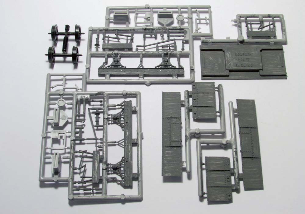
Fig. 42 The basic parts of a simple open wagon kit, such as the Cooper Craft coal wagon kit, with some of the parts painted before removal from the sprue.
Whilst waiting for the underframe to harden off, the next step is to prepare the white metal buffers. Using a 2mm diameter drill bit, first bore out the pre-drilled holes in the buffer beam by gently twisting a pin vice with the drill bit clamped in place. The shaft of the buffers to go into the holes in the buffer beam will probably need fine adjustment with a needle file to ensure a snug push fit through the holes. Do not force the buffers through the holes as this will stress the plastic and could lead to the buffer beam distorting or even breaking.
When you are happy with the fit of the buffers, these are inserted and a spot of contact adhesive (for example, UHU) is used on the rear face of the buffer beam to hold them in place. A coupling hook can also be inserted and fixed at the same time, either the plastic one supplied with the kit or a replacement white metal component. The wagon ends can then be left to harden off overnight.
The next step is to add brake gear and Dean Churchward (DC) brake handles to the underframe before adding the wagon body, starting at one end and working around the wagon one side at a time, as shown in Fig. 43. I found that to ensure a flush fit of the end walls of the wagon to the underframe, it was necessary to remove any excess buffer shank protruding from the rear face of the buffer beam. To do this, I carefully trimmed the shanks using a side cutter (white metal is soft and easily cut), followed by the use of fine files to smooth the cut surface.
Liquid polystyrene cement is used to fix all of the plastic kit components together and is applied sparingly using the needle applicator on the glue pot or with a small brush.
When the body is square at the corners, it is then left to harden off upside down on a glass tile to ensure a square flat top surface to the wagon sides. When dry, use fine files and fine-grade glass paper to round off the wagon corners between the top edge and the lower edge rivet strip detail to match the profile of the prototype, as shown in Fig. 44.
Rounding off the corners should be carried out gently and a small bit at time, checking regularly to see that the corner remains vertical and square at the inner joint edges. Use a photograph of the prototype to compare what the final shape should look like. Do not attack the model as though you are grinding down the edge of a door, otherwise the wagon will end up with misshaped corners or, worse still, too much of the plastic body will be removed and you will end up with a hole!
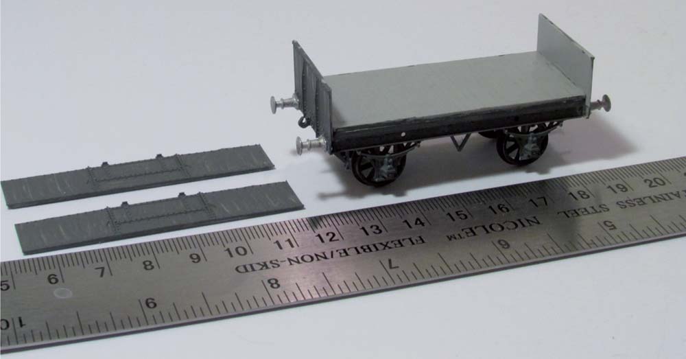
Fig. 43 After removing and cleaning up the parts, bodywork construction commences with the underframe and then addition of the wagon ends and sides.
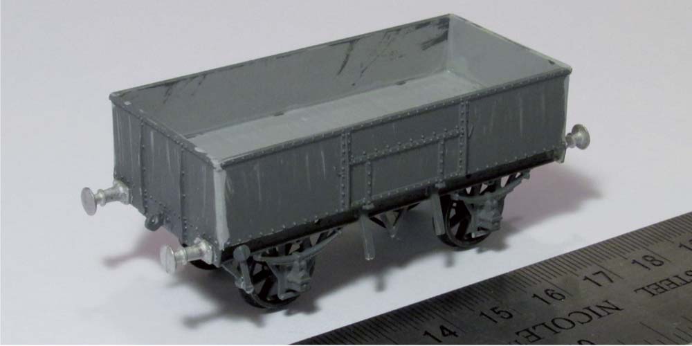
Fig. 44 To improve the look of the finished model use a flat-face file to round off the body corners to match the prototype.
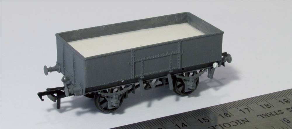
Fig. 45 Final painting of the wagon prior to application of decals and the trial fit of a false floor for the wagon load, described further in Chapter 4.
When satisfied with the shape of the corners, apply a second coat of GWR wagon grey paint and pick out the brake handles in white, as shown in Fig. 45. You will also note that in Fig. 45 I have begun the process of adding a false floor and load, as described in Chapter 4 and shown in Figs 110–114.
Transfers were Pressfix from the HMRS range, as I prefer these to the waterslide decals provided with the kit (see Fig. 115). As the wagon is open, you have the choice as to whether you wish to add a load or run it empty. I chose to add a load of coal for use on my layout and constructed a load as described in Chapter 4.
CONSTRUCTING PRE-PRINTED KITS
Another type of kit, although less common these days, is the pre-printed wagon kit, where the decals have been printed on to a pre-painted or coloured plastic body. All the modeller needs to do is carefully cut the parts from the sprues and fix together. A couple of examples are included in this section (an open wagon, van and tank wagon) for reference, to show how these types of kits are put together and, more importantly, to provide a few tips for the modeller when working with these types of kits.
The quality of the kits and moulding is very good. The key issues with these types of kits are the careful removal of the parts and the sparing use of glue to fix them together to avoid spoiling the coloured body parts and pre-printed decals. All the examples that are included here make up into nice well-detailed wagons, although the Slater’s open wagon and Ratio van are unfortunately both discontinued items at the time of writing. The examples used here were obtained from eBay for reasonable prices of approximately £10 per kit including postage.
CONSTRUCTION OF A PRE-PRINTED VAN KIT
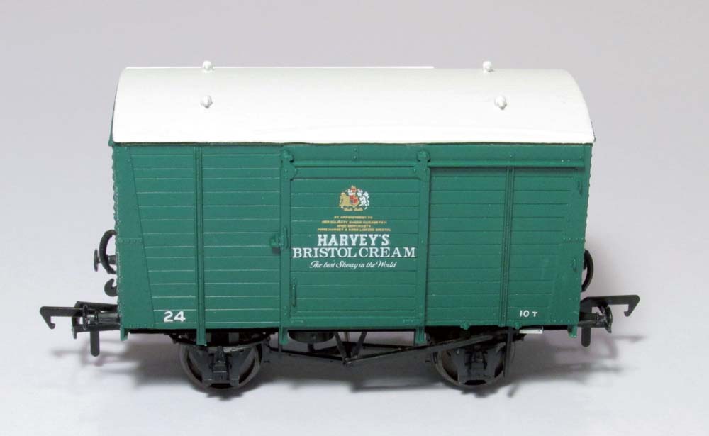
The Ratio pre-printed kit for the Harvey’s Bristol Cream van is a relatively old kit, but it is possible to occasionally pick up unmade examples of the kit at sales, swap meets or from on-line auctions. This van kit included metal wheels and brass bearings.
Construction of the van kit is relatively simple and straightforward. The instructions provided are clear and concise, and when combined with the exploded parts’ drawing provide a reasonably comprehensive set of instructions for putting the kit together. As discussed earlier, it is important to read the instructions fully before starting and to familiarize yourself with the parts and, with the aid of the exploded drawing, to visualize how the kit will go together before starting anything.
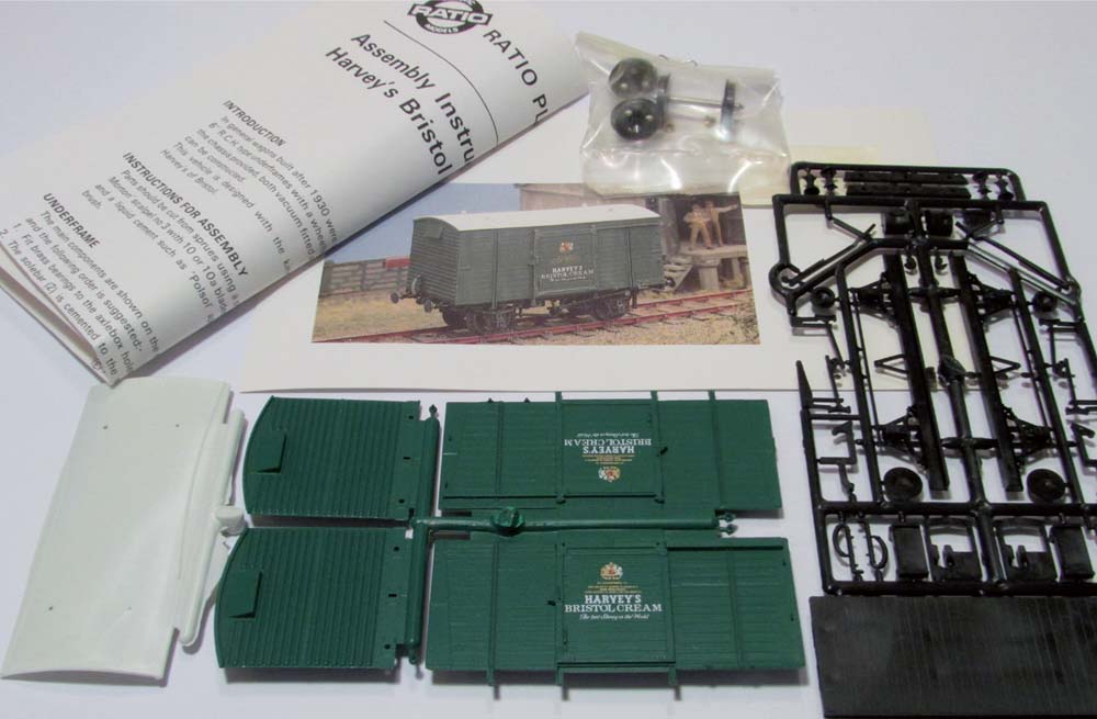
Fig. 46 The Ratio Models pre-printed Harvey’s Bristol Cream van kit as removed from the box to study before construction.
I found that to install the brass bearings in the axle boxes it was necessary to drill out the boxes with a 2mm diameter bit, to ensure that when inserted, the flange on the bearing fitted flush with the inside face of the axle box. To drill out the axle boxes, take a 2mm drill bit and, using a pin vice or Archimedes’ fine drill, twist the bit by hand to remove a small bit at a time, being careful to check that the drill bit does not go too far into the axle box.
After checking to ensure the correct depth, I then used a spot of cyanoacrylate (super glue) in each axle box and pressed home the brass bearings using the flat end of my tweezers or a small screwdriver to get a flush fit, being careful not to damage the bearing. All of this work on the fitting of bearings is accomplished either before removing the sole bars from the sprue or after removing them but before commencing construction of the underframe.
Following the instructions provided, the underframe is constructed first by fixing the sole bars on to each side of the main floor component, as shown in Fig. 47. This was placed with the upper floor surface down on to a glass tile to ensure that it stayed flat and then the wheel sets were installed to check all was square, i.e. that the axles were perpendicular to the floor edges and the wheels were free-running in the bearings. I use a small block of wood each side of the underframe to keep it all square whilst the adhesive is drying and I leave the wheels in place whilst the glue hardens off to ensure that it remains square. Put this to one side and leave overnight to dry to get the best results.
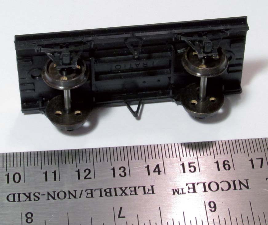
Fig. 47 The kit is best started with the completion of the underframe construction before adding the bodywork.
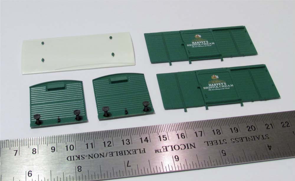
Fig. 48 With pre-coloured body parts, removal of the parts from the sprue and cleaning up needs to be carefully carried out to prevent damage to the outer finished surface.
Fig. 49 The fine detail parts to add to the kit are also pre-coloured and when fixing care should be taken not to over-apply the adhesive.
Whilst the underframe was drying, I removed the body parts and cleaned up the flash from the moulding process as preparation for the next stage of construction. When the underframe has hardened off, the next stage was to add the detailing parts, starting with the brake gear, then the vacuum cylinder and then the brake lever.
The kit as supplied has axle box tie bars moulded in place, which need to be removed according to the instructions. If the tie bars are carefully cut flush with the axle box at each end, you will be left with two pieces of thin plastic rod – I use this to form the link bars between the two sets of brake gear. This is not part of the instructions, but a way of adding a bit more detail to your wagon kit, a subject covered in more detail in the next chapter.
Once finished with the brake gear and connecting rods, the next stage was to fit the coupling of choice. The mounting blocks supplied with the kit for the tension lock coupler were cut from the sprue for use with my preferred choice of coupling, the Bachmann mini-type, although other types and methods of coupling can be considered and it is at this stage, before commencing the construction further, that the modeller needs to check and fit their preferred coupling arrangement.
Before constructing the body of the van, I fixed the buffers and cosmetic coupling hooks to each buffer beam that forms part of the end wall mouldings. It is easier to fit these components with the end wall lying flat on the work surface, rather than when the body has been fixed together. It is often necessary to ream out the holes for the buffers and the coupling hook, all of which is less fiddly and easier to undertake prior to construction. Once happy that the buffers and hooks are fitted squarely, these can be left for the glue to harden off.
The body was constructed around the floor/ underframe sub-assembly, starting with one end wall and one sidewall. When satisfied that these walls are squarely joined and fixed, the second sidewall and end wall can be added to form the whole box of the body. The upright vacuum pipes shown fitted to the wagon should be added after the body has been fixed together, as they will easily get knocked off or damaged if added before fixing the body together.
The ventilators were cut from the sprue and carefully pushed through the pre-drilled holes in the roof, before fixing with a spot of glue on the underside of the roof. Fixing the ventilators in this way avoids any unsightly glue build-up on the top surface of the roof. When dry, the roof and ventilators were painted matt white and left to dry before fixing the roof to the body. If preferred the underframe could be painted matt black and the brake lever handle picked out in white.
CONSTRUCTION OF A PRE-PRINTED TANK WAGON
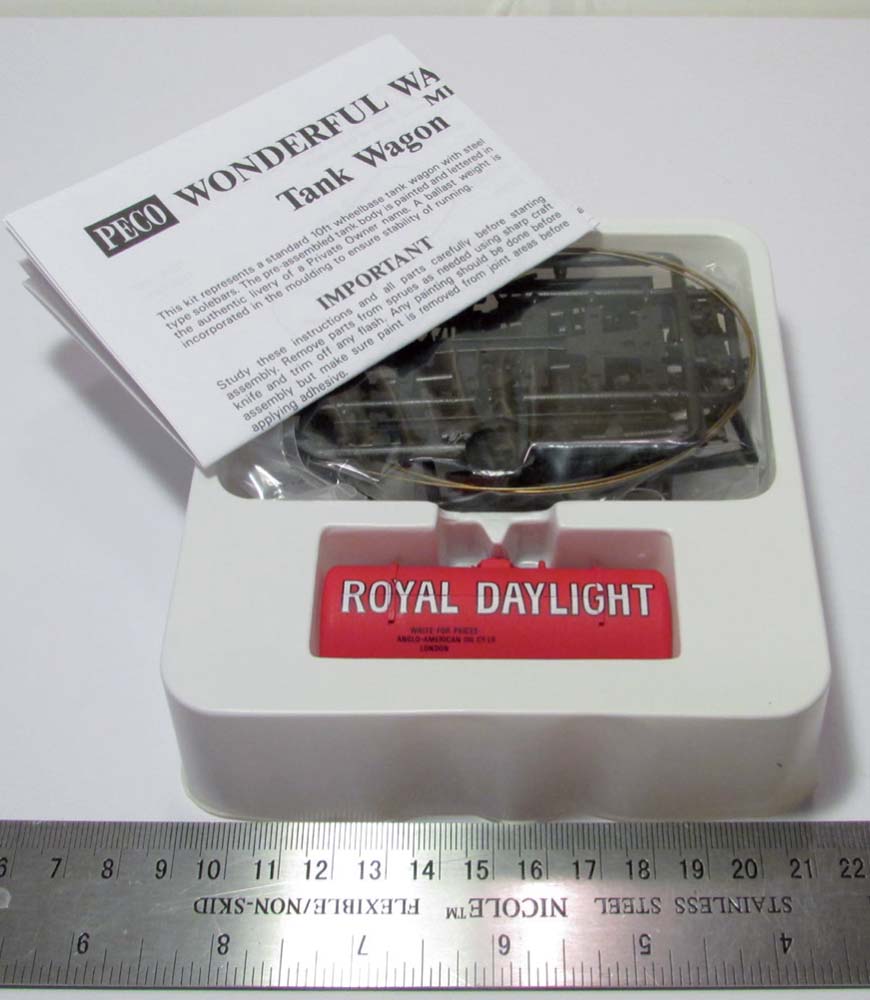
The PECO tank wagon kit is one of four types of tank wagon that can still be picked up for around £10 to £12 (at the time of writing) and the Royal Daylight fuel tank wagon illustrated here makes an extremely neat and well-modelled item. I have used another version of the tank wagon kit, the United Dairies milk tank, as the basis for a conversion project, to create a representation of a GWR milk tank wagon, as described further in Chapter 5. The PECO tank wagon kits are weighted with metal weights inside the tank body and make up, with care, into a model that runs extremely well on the plastic (Hardlon) wheels provided, which if preferred could be replaced by metal wheel sets.
Fig. 50 The completed model when carefully put together is difficult to distinguish from RTR items and makes a colourful addition to your PO wagon fleet.
The PECO Royal Daylight tank wagon kits come in a box with the main tank already preformed, painted and lettered and displayed in the window on the box lid. Opening the box reveals a tray of parts and a comprehensive instruction sheet, with both written instructions and a step-by-step picture guide.
The kits comprise relatively few parts (see Fig. 52) to be fixed together and a finished model can be accomplished in a relatively short period of time. The one important point to bear in mind with this type of kit is the choice of adhesive to use to fix the parts together. The varied types of plastic used in the kit construction necessitate the use of a super glue type adhesive; standard polystyrene cement will not fix some of the material types together.
The instructions are clear and easy to follow; the only additional advice would be to make sure that you do a dry run of each section, so that you understand what the final piece will look like before fixing permanently with the super glue.
Adding additional or extra detail to the model is for preference; I chose to model the kit as per the instructions and did not add any additional detail components, except for adding the connecting bar between the two sets of brake gear on each side of the wagon, using an off-cut of the thicker gauge wire supplied with the kit for use as tension rods. For the purposes of this example, I also chose to use the Hardlon wheels supplied with the kit, running in the PECO plastic bearings, as these proved to run extremely well.
Once the chassis was completed, I opted to paint all of the underframe matt black to hide glue marks, areas where fine adjustments had been made using a file and to take the ‘plastic look’ off the finished model.
Fig. 51 The PECO Wonderful Wagon tank wagon kits come in a protective tray that can be used as your temporary storage for parts during the assembly process.
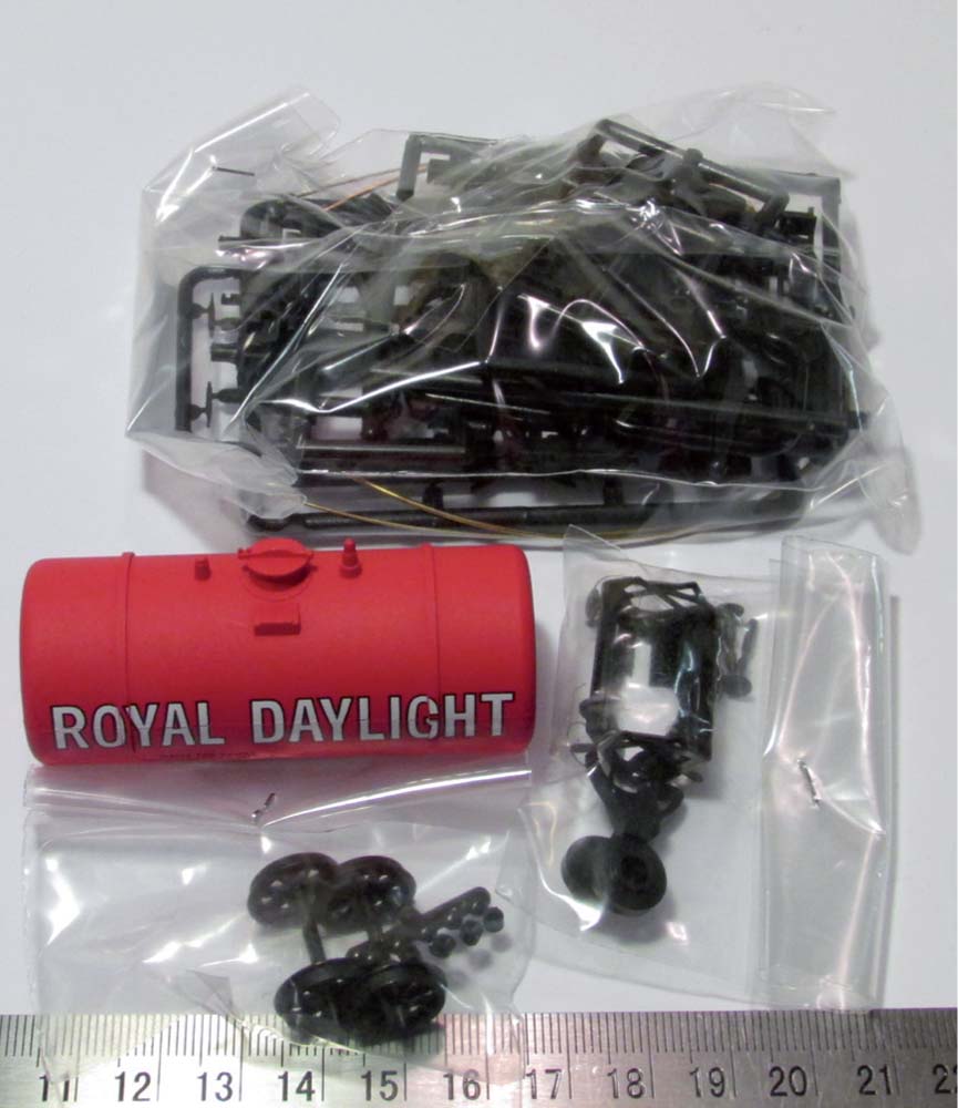
Fig. 52 The pre-formed and painted tank in its finished livery and decals; chassis parts in one bag, metal ‘W’ irons in another, and wheels and bearings in another.
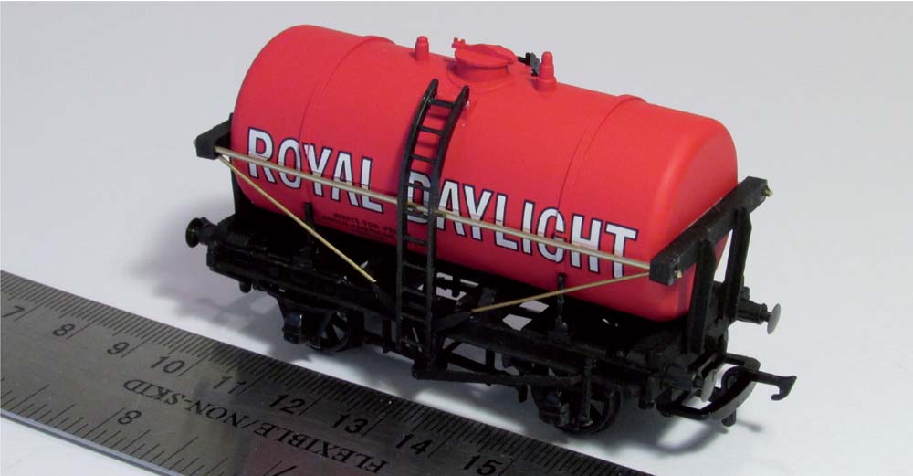
Fig. 53 The construction of the model can be quickly and easily accomplished and the completed model looks good on the layout.
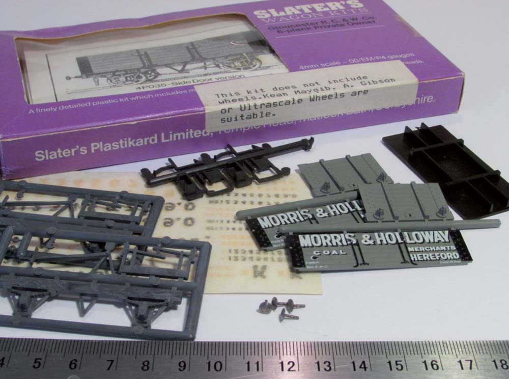
Fig. 54 An example of a pre-printed open wagon is one of the many formerly produced by Slater’s Plastikard, such as this example of a coal wagon kit representing a Morris and Holloway of Hereford prototype.
CONSTRUCTING A PRE-PRINTED OPEN WAGON
The Slater’s pre-printed open wagon, used as an example here, is currently not available as a new kit, but unbuilt examples of this particular model, and many more similar wagons, can still be picked up at swap meets, fairs or via on-line auctions for reasonable prices around the £10 mark. This particular example is the ‘Morris and Holloway’, Coal Merchants of Hereford wagon with a grey overall body, ironwork picked out in black, black underframe and white shaded-black lettering.
The Slater’s pre-printed open wagon kits do not come with wheels and bearings, so it is up to the modeller to supply metal wheels and bearings from another source. In this case I opted to use Gibson 12mm diameter open-spoke wheels and brass bearings.
The ends and sides were carefully removed from the sprues and, following the instructions, one end and one sidewall were fixed together after cleaning up the sprue mould points and mitre joints at the corners. I made use of my glass tile here to check that the joint was square and the top edges were flat when joined. I also used a small 90-degree set square to check that the joint was a right angle. This process was repeated for the other end wall and sidewall and then both sub-assemblies were left to harden off before proceeding.
As the sides of the wagon body are pre-printed, it is essential to be sparing with the application of liquid adhesive to the mitre joints, to prevent surplus glue squeezing out of the joint during fixing, on to the pre-coloured and lettered surfaces. I found that the use of ‘Revell Contacta Professional’ with application of the liquid cement via a fine needle applicator to be extremely useful in these circumstances. The trick is to apply a small amount, even a few drops, sufficient for the joint to hold and then go over the inside of the joint with a fine stream of liquid cement to strengthen the join.
Whilst the body sections were hardening, I took the opportunity to paint the underframe and ironwork detail on the sole bar matt black using a fine brush. The painted parts were left to dry for twenty-four hours before proceeding further. Construction of the kit then progressed following the instructions provided. The body side sub-assemblies were fixed together before dropping the floor in to place. The only change from the instructions that I made to the kit was that I chose to replace the plastic coupling hooks with white metal components.
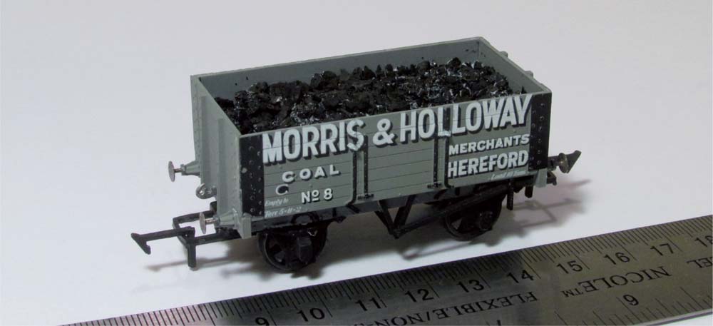
Fig. 55 The completed model ready-to-run requires very little additional painting and the addition of a coal load adds to the realism of the model.
On completion of the wagon, I opted to fit a permanent coal load to the wagon, using the technique described in Chapter 4, and added a makers’ plate and wagon running number using Pressfix decals.
CONSTRUCTING MORE COMPLICATED KITS
The construction of more complicated wagon kits should not be seen as something for the more advanced modeller. The kits produced by the likes of Parkside Dundas, 51L, Cambrian Models and others, as well as in the past by the likes of Colin Ashby, Ian kirk, Falcon Brassworks and others, only differ from the more straightforward kits by the number of parts required, the inclusion of more detailed parts requiring sub-assembly before construction of the overall kit and the requirement on the part of the modeller to provide paint, couplings, wheels and decals of choice.
CONSTRUCTING MORE COMPLICATED PLASTIC KITS
The construction of these types of plastic kits is very similar to the construction of the more basic kit, except that there is usually much more detail and sub-assembly work required to complete the overall model. Good examples of the more complicated plastic kits are the ones supplied by Parkside Dundas, of which I have built a fair number over the years, as well as using some of their kits as the basis for conversions, as shown in Chapter 5.
Typically these kits comprise much more choice in terms of components that can be used to create different versions of the prototype and therefore it is essential that when looking to start on one of these types of kits you carry out your research and try and get a picture or two of the completed prototype to which you can refer.
As examples of this type of kit, I have included some images of completed models from the Parkside Dundas range that I currently have operating on my layout, some of which were built over thirty years ago but which are still going strong. Of these kits the most complex, or perhaps most fiddly to get right, is probably the Bloater wagon with all the external additional detail that can be added, as shown in Fig. 57.
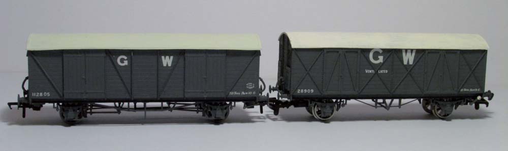
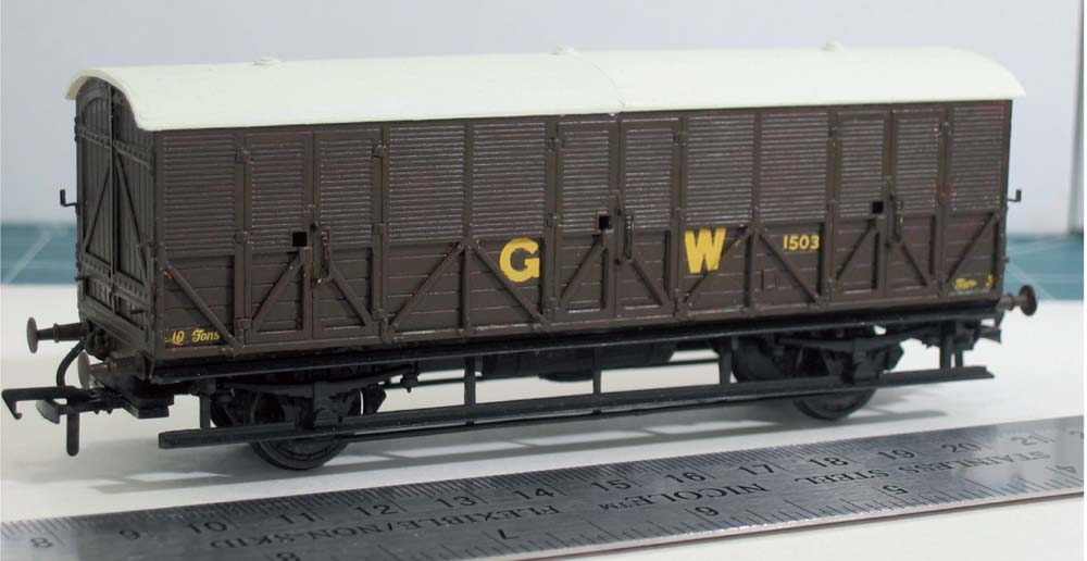
Fig. 56 The Parkside GWR Mink D and Mink G van kits are more detailed and require the modeller to provide decals.
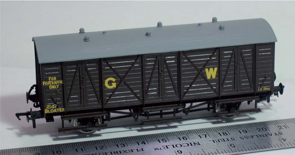
Fig. 57 The additional fine detail evident on the Parkside Bloater kit requires a steady hand and patience, but the finished model is worth the effort.
The key lesson that I learned when building these kits was that it is important to take your time and not to rush during the construction process. To watch the completed model, nicely detailed and painted, running on your layout is extremely satisfying and justification for the time spent putting it together. In Chapter 4, I have included a step-by-step guide to building and detailing a more complicated kit.
CONSTRUCTION OF A WHITE METAL WAGON KIT
To show the techniques used for the construction of a white metal kit, a 51L white metal kit of a Cambrian Railway open wagon has been used as a worked example. The kit as supplied comprises a number of white metal parts, two pieces of plasticard and two brass frets. The white metal parts form the main body, as well as the detail components for the brake gear and buffers. One of the two pieces of plasticard is embossed to represent wooden planks for the wagon floor, whilst the second, thinner sheet of plasticard is intended as packing material below the floor.
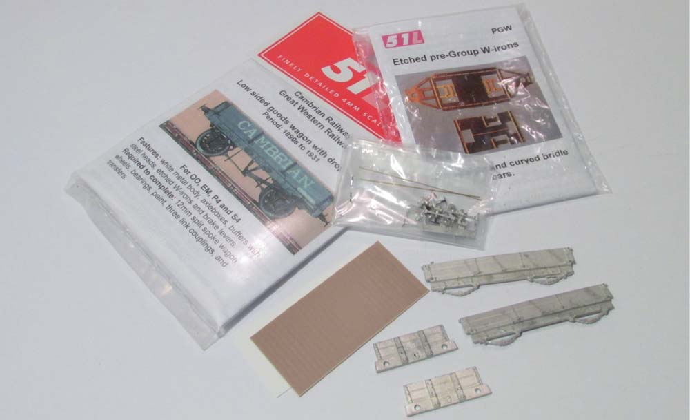
Fig. 58 The 51L white-metal kit of a Cambrian Railway’s slate wagon provides a simple open wagon kit of an unusual prototype.
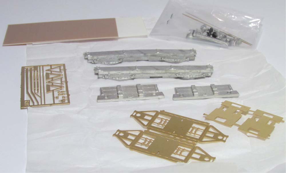
Fig. 59 The kit comprises a selection of brass and white-metal components, as well as plasticard for the floor, requiring the modeller to use a number of different adhesives to complete the model.
The first of the two brass frets supplied has etched parts for the brake lever and ‘V’ hangers. The second brass fret is for the ‘W’ irons and supporting frames to build either a rigid or a compensated (rocking) chassis, as shown in Fig. 59. Starting with the brass fret, the ‘W’ irons were removed with a sharp pair of fine scissors and the parts fold up along the half-etch lines. A tip here is to apply a thin stream of solder or adhesive to the inside of the fold line to reinforce the part.
Using a 2mm diameter drill bit ream out the holes in the ‘W’ irons for the brass axle bearings. This may also require the use of a fine, round broach or file to open out the hole to accept the bearing. Insert the bearings, being sure to insert them the correct way round, and push so that they are flush with the internal face of the ‘W’ iron. Take the white metal axle box castings and carefully ream out the holes that go over the brass bearing. The white metal components are soft, so any reaming needs to be carried out a small amount at a time to avoid any risk of damage to the part.
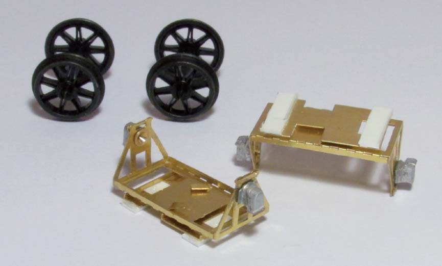
Fig. 60 The first part of the model to make up is the etched brass compensation units; these are folded up and the wheels test-fitted.
When satisfied with the fit, the white metal part should sit over the brass bearing and flush with the external face of the ‘W’ iron. This can then be held in place by streaming a small amount of super glue around the join using a fine piece of wire. Leave to set, then spring the ‘W’ irons apart gently and drop in the wheel sets to check that they are free-running. Next, fold up the brass base plate and test fit to the ‘W’ iron sub-assembly. The plates can be folded up to make either a rigid or rocking chassis; the choice is down to the modeller. When completed, set aside these elements of the kit and start on the body.
The main wagon body comprises four white metal parts, with the sole bars and springs forming part of the sidewall castings. Clean off the flash from the moulding process and then take one end and one side and fix together. Use a flat glass tile to ensure that the parts are level and check that the corner is 90 degrees. Whilst these parts are setting, repeat the process for the second end and sidewalls. Leave both sub-assemblies to dry for at least a couple of hours, then fix together and check to ensure it is square, then leave overnight to harden off.
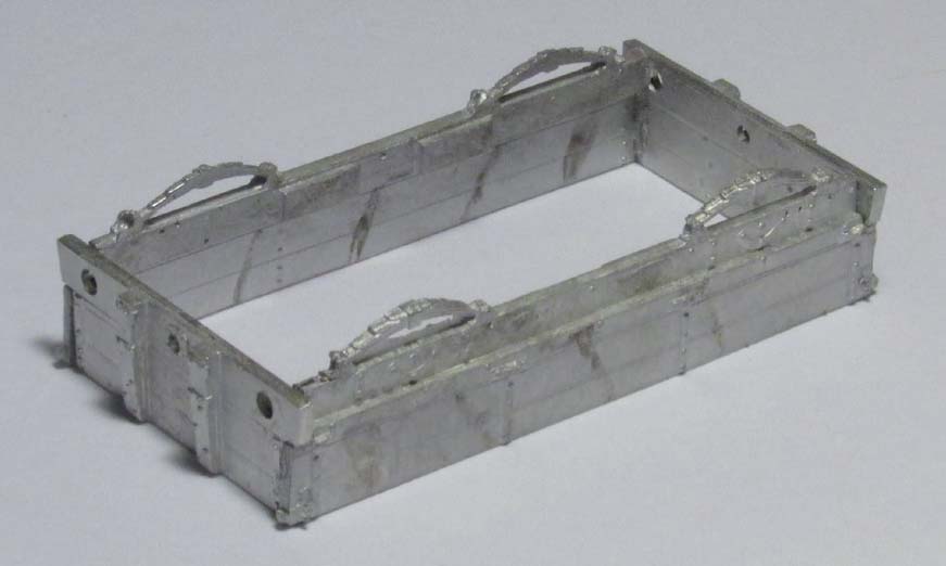
Fig. 61 The white metal bodywork is fixed utilizing a flat glass tile surface to ensure it remains square until set.
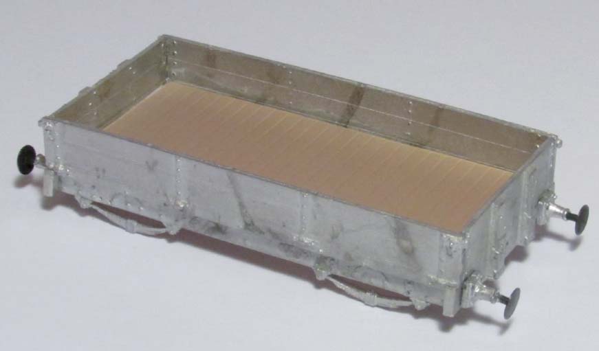
Fig. 62 The plasticard sub-floor and floor sections are inserted from above into the body and fixed securely in place with impact adhesive.
Measure the internal dimensions of the wagon body and cut the floor and sub-floor to size. Bore out the holes for buffers and coupling hooks, and fix in place. Install the floors as described in the instructions and as shown in Fig. 62. Place the folded-up ‘W’ irons on the underside of the floor to check the height relative to the springs. On the example that I constructed, I needed to add 1mm of plasticard packing to raise the level of the ‘W’ irons. When satisfied, fix in place and check running qualities.
When the ‘W’ irons are fixed, install the ‘V’ hangers on the internal and external face of the sole bar. Prior to placement, the ‘V’ hanger should be bored out with a 0.5mm drill to allow insertion of a connecting rod formed from brass wire, as shown in Fig. 63. The white metal brake gear will also need to have the central crank opened out with the same drill bit. To ensure all of the pieces of the brake gear are aligned, first fix the brake gear in place between the wheels, ensuring alignment with the wheel treads (see Fig. 64). I found it was necessary to use a scrap piece of plasticard to provide support to the brake gear.
Fig. 63 Assembly of etched brass ‘V’ hanger and brake lever can be undertaken whilst the body is hardening off.

Fig. 64 The compensation units should be fixed to the floor and, where necessary, plasticard packing added to ensure that the wheels are aligned with axle box springs.
Next thread the brass wire through the brake gear and then thread the brass internal and external ‘V’ hangers on to the same piece of wire, using 0.5mm wire as a jig to check alignment. Fix in place with a spot of super glue, fixing the external ‘V’ hanger in place last. I found the external ‘V’ hanger needed to be trimmed to the correct length – check with a trial fit before fixing in place. Use a piece of the 0.5mm wire at least 20mm long to ensure it extends well beyond the ‘V’ hanger and brake gear. Fold up the brake lever and ratchet from the etch parts; fix the lever in place threaded on to the 0.5mm wire and hold in place with a spot of super glue. When hardened, trim the wire with side cutters.
The plasticard floor for the kit is embossed to represent planking and is supplied in a brown colour. I used the GWR wagon grey as a thin wash coat over the floor to let some of the brown show through to represent a used wooden floor. Using photographs of the prototype from Green (1997), decals were applied using HMRS Pressfix sheets.
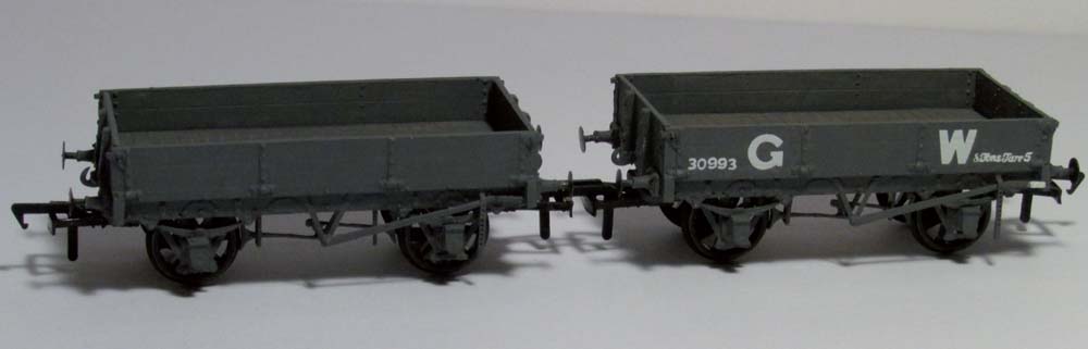
Fig. 65 The wagon on the left has been painted and is awaiting decals to match the completed model shown on the right.
These wagons were originally built by the Cambrian Railways to primarily transport dressed slate from the quarries/mines in North Wales to the rest of the country or to the ports for export around the world. You could consider fabricating a slate wagon load for your finished wagon or, alternatively, resin cast slate loads are available from a number of sources for painting. Scratch building a load could be considered using thin card or plasticard.
CONSTRUCTION OF A BRASS WAGON KIT
Brass kits are generally perceived to be more complicated kits for the more experienced modeller. Typically, these kits require the modeller to provide wheel sets and brass bearings, but generally come with much more detail than would be typically found in a plastic or white metal kit. The level of additional detail and improved running performance of the completed model due to the weight are some of the reasons for making models out of brass. However, it is down to the skill of the modeller, as discussed earlier, and brass kits tend to be more expensive, but when built well and carefully finished off, they do look extremely nice on your layout.
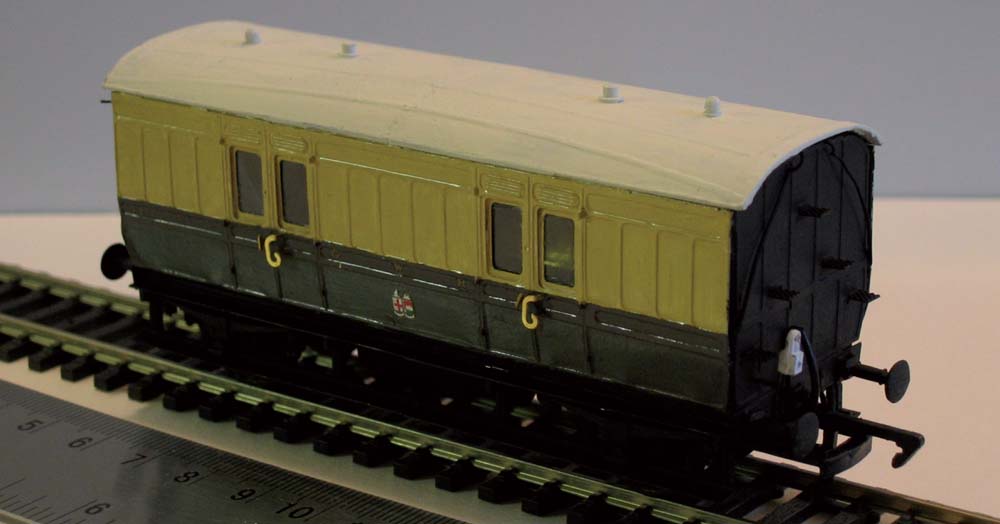
To show the construction of brass kits I have looked at examples that I have made for both part and complete kits. One of the first brass kits that I attempted was the construction of the Shire Scenes GWR W1 Parcels Van. This kit comprises brass body sides, to which you can, if preferred, add brass end walls from the same or another supplier. The kit makes use of the Ratio GWR four-wheel coach kits for a donor underframe and roof, and if not using brass coach ends, you could also re-use the plastic coach ends. The construction of this kit was described in an article that I wrote for Railway Modeller, published in 2010, and from this I learned some extremely useful lessons and techniques for working in this medium, which I have highlighted below.
First, the instructions provided with the Shire Scenes kits are straightforward but could do with more detail and illustrations, and whilst they probably make sense to an experienced model maker, they would likely cause some head scratching from a less experienced modeller. It is essential to read all of the instructions before starting any of the work. The brass frets were clean and needed no clean-up of flash, just careful removal, with either a sharp knife or sharp scissors, of the relevant parts as required. The kit makes up into an excellent model with just the odd dab of cyanoacrylate glue required to hold folded sections in place.
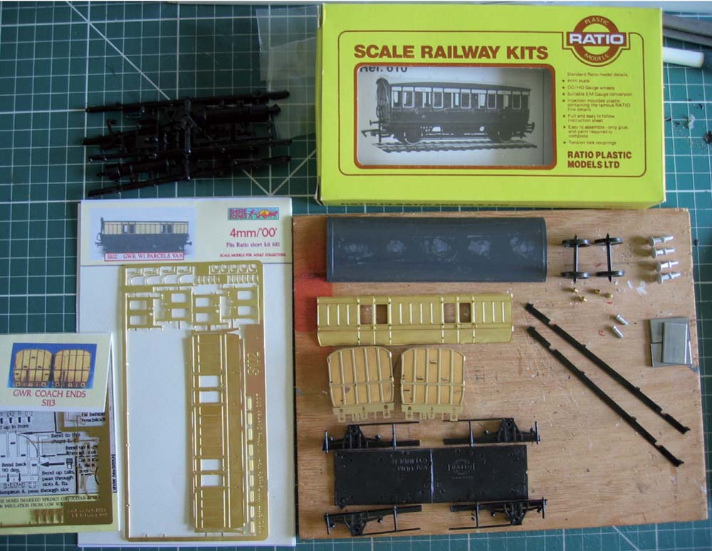
Fig. 66 As a starter kit in brass, the Shire Scenes etched brass body conversion kit to produce a W1 Parcels Van is a good start, making use of a Ratio four-wheel coach for the underframe and roof sections.
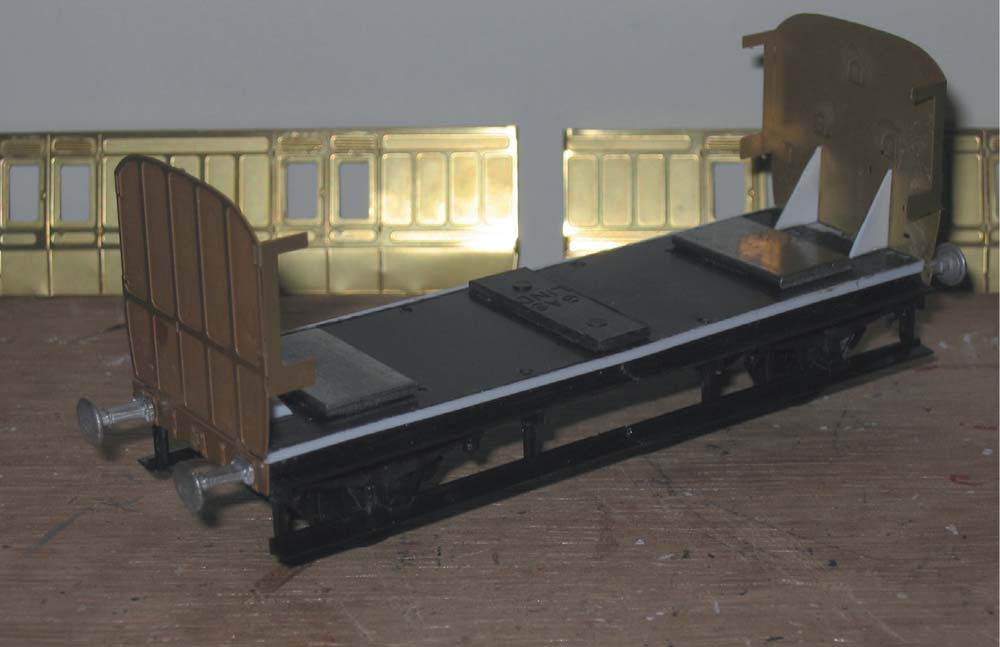
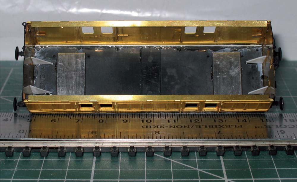
Fig. 67 As part of the construction process, the underframe is shortened and brass replacement end walls added before the brass sides are shaped to match.
Bending the tumblehome on the lower portion of the coach sides, i.e. the slight inward bend of the bottom of the coach sides, was the only difficult task with the construction of this kit. The instructions supplied with the kit were a bit vague on this process, so I used the following method to accomplish the correct shape to the bodywork. I started by carefully bending the coach sides between my thumb and fingers working slowly from one end to the other. If this is done a small bit at a time and with patience, I found that you can achieve a good, even shape to the body sides to match the correct overall profile required. This was checked against the end profile of the replacement brass end walls to ensure that they would match when brought together to form the body.
Installation of the droplights required careful folding of very small tabs, which when inserted into the preformed holes in the coach sides form the door hinges. To get these tabs folded and the whole assembly shaped to match the inside curvature of the sides, I found to be quite difficult and required a lot of patience to get it right. Once achieved though, the result was worth the effort.
The replacement coach end sections are cut from the fret and the various folds made to the side returns and the buffer beam details, with use of super glue as required, to hold parts in place. Buffers were then added and allowed to harden off before attaching the coach ends to each end of the floor.
The instructions with the Shire Scenes kit state that the floor, sole-bars/side steps and roof from the donor Ratio coach kit will need to be shortened by approximately 8mm. Having measured this before construction started though, I was not convinced this was completely accurate. Therefore, I opted to first fold up the brass section coach sides and ends, and then measure these completed sub-assemblies to get the actual length required for the floor and so on. The amount of shortening may vary depending on the construction of the brass sides and to some degree by the moulded plastic parts of the Ratio chassis kit.
Once I offered up the sides to the floor, I could then determine by how much the floor, associated running gear and steps needed to be reduced. To keep the ‘W’ irons in the correct position relative to the prototype, I opted to cut a section from the middle of the relevant parts of the underframe, rather than trim a section from each end. I then re-joined the shortened halves together to form the new underframe for the brass kit (see Fig. 67). The method of shortening the chassis is not stated on the instructions for the Shire Scenes kit and is an extremely fiddly task that requires patience on the part of the modeller to ensure clean and square joints, as well as to limit damage to the Ratio kit parts.
Fig. 68 With the body shell completed, the curvature of the sides, referred to as the tumblehome, has been formed to match the end wall profile.
To achieve the shortened chassis, the floor was measured up with cut lines marked at 49.5mm from each end. A razor saw was used to cut the floor along these lines and then each half filed smooth and square. The two ends were re-joined on a flat glass surface and glued together with liquid polystyrene cement. The floor was then put to one side to dry whilst a similar operation was carried out on the sole-bar/’W’ irons and then the side steps. On reassembly, I found that the axle tie bars and the side steps were quite fragile and I opted to reinforce the joints with short sections of plastic card strip located on the inside of the assembly and thus not visible unless the model is turned upside down and, once painted black, almost invisible. Alternatively, the plastic tie rods could be removed and replaced with suitably sized brass rod.
The axle boxes were drilled out to 2mm diameter to accept the brass bearings, which were fitted before gluing the sides on to the floor. Once fitted, the wheels were installed to check free-running before they were hardened off. Clasp-style brake shoes and other underframe detailing were then added at this stage and then the entire chassis assembly was then put to one side to harden off.
The same principle of cutting out a central section to reduce the length was also applied to the roof, so as to maintain the end profiles. Cutting the central section out with two cut lines perpendicular to the long axis of the roof ensured that the roof rain-strip detail was not unduly affected. To ensure the correct length for the roof, this operation was left until after the coach ends and sides had been attached to the floor and allowed to set. Before any cutting took place, the moulded gas lamp tops were carefully removed and the roof section filed flat to remove these protuberances.
The roof section was then marked and a central piece about 9mm in length was removed with two cuts of a razor saw. The two ends were then filed on the cut lines and re-joined using liquid polystyrene cement to ensure a ‘melting’ of the plastic sections into one another and thus reduce the visibility of the joint line on the re-assembled roof. The removed central section was shaped with a craft knife and re-used as a strengthening section on the inside of the roof, under the join line of the two ends. Once the glue had hardened off, the roof joint was carefully filed to smooth out the join line.
Once the underframe assembly had hardened off, the first stage was to attach the coach ends. This was accomplished with super glue and I used small right-angle triangle sections, formed from plastic card on the inside of the model, to ensure that the coach ends were at 90 degrees to the floor and square. Once set, work could then begin on adding the detail parts to end of the coach.
Fig. 69 A completed GWR W1 Parcels Van conversion with painting, decals and fine details added.
The coach sides were then added and, if the instructions on folding the top side returns are followed, they effectively ‘hang’ off the side returns from the coach ends. When putting the parts together in a trial assembly, I found that the Ratio plastic floor unit was about 1mm too narrow; so thin, plastic card packing strips were fashioned and glued to each side of the floor to get the correct width. Once satisfied with the fit of the sides, these were then attached with super glue. I found that running the tip of the super glue tube along the join between the bottom of the coach side and the floor also helped to strengthen this joint after the initial fix, as seen in Fig. 68.
Turning to the roof, the shortened section was offered up to the body and fine adjustments made by filing to achieve the correct fit. The positions of the shell ventilators and gas lamp tops were marked on the roof using the prototype information. Holes were drilled in the roof to accept the white metal replacement components, which were fitted to the roof before painting and final fixing to the body. Before fitting the roof, the body and underframe were painted appropriate colours and glazing added to the door windows (see Fig. 69).
Following on from the Parcels Van, I have since completed a number of other kits in brass, including the Shire Scenes GWR Siphon C milk wagon and the 51L GWR Horse Box. The Shire Scenes Siphon C is another body kit similar to the W1 Parcels Van, except that the body is formed from two layers of brass fret and the wagon ends are integral to the kit, not separate additions.
The kit again makes use of the Ratio four-wheel coach chassis and roof, duly modified to the correct length, similar to the process described above for the W1 Parcels Van. The kit costs around £18 and is an extremely good starter kit for those modellers graduating to brass from plastic. Whilst the modifications to the roof and chassis are fiddly, providing care is taken the resulting product is a very good model (see Fig. 70).
Fig. 70 A range of kit conversions is available from Shire Scenes, including the four-wheel GWR Siphon C Van.
When making up my kit of the Siphon C, I chose to use metal fine-scale wheels running in brass bearings in lieu of the wheels provided with the Ratio coach kit, as well as adding a white metal vacuum cylinder, vacuum pipes and buffers to give the correct pattern to match the prototype and to provide additional ballast weight to improve the running characteristics of the finished model.
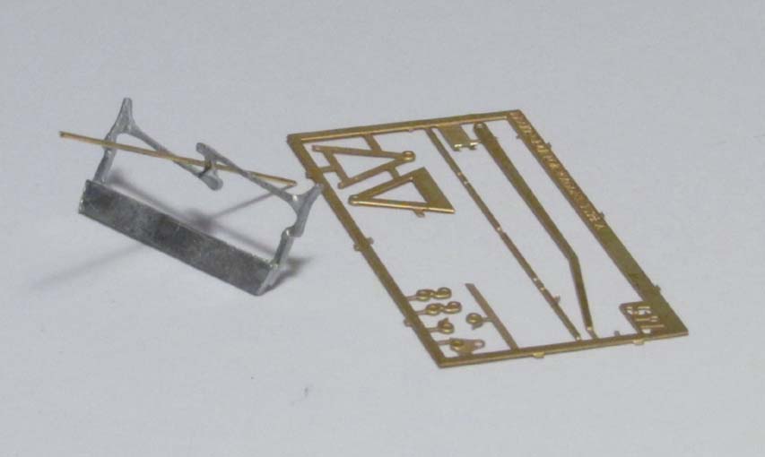
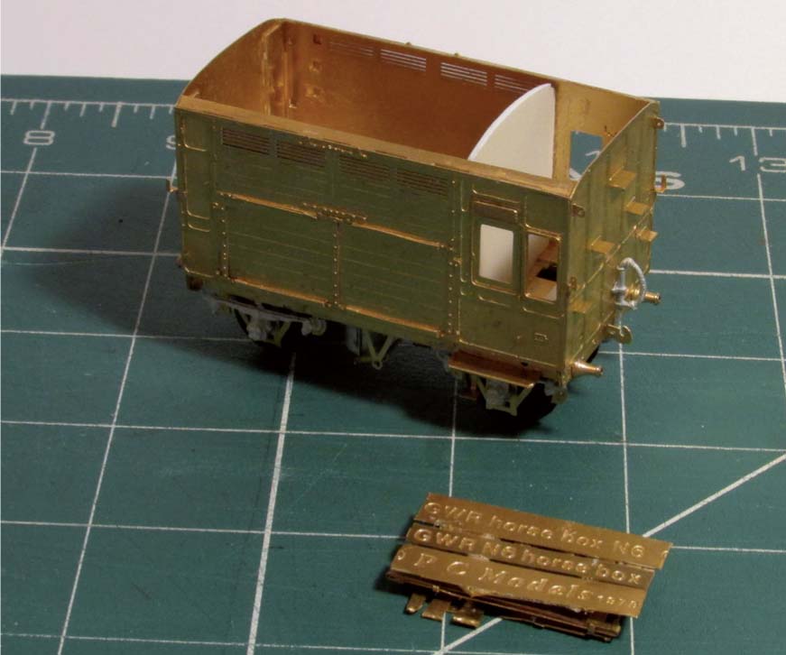
In terms of the 51L brass kit of the GWR N6 Horse Box, this kit comes in one large fret, including compensation units for the wheel sets, as shown in Fig. 71. Additional parts also included with the kit comprise a section of plastic card for the internal walls, turned brass and steel sprung buffers, white metal axle boxes, springs, vacuum cylinder and other detail parts, and a selection of brass wire for the hand rails and brake rods.
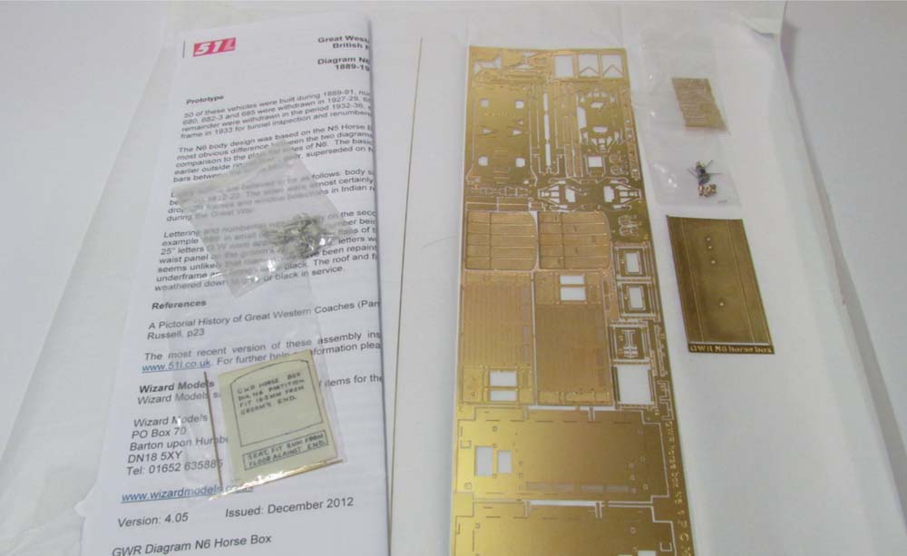
Fig. 71 An example of a complete brass wagon kit is the etched brass fret for the GWR Horse Box produced by 51L. This kit includes all but a few fine detail parts on a single brass fret. Additional white metal components are also provided, along with a section of plasticard for the internal wall and seating.
A small fret for brass three-link couplings is supplied, although I chose to add small tension lock couplings (Bachmann ref: 36-025) for use on my layout. The couplings and mounting blocks, plus the fine-scale 14mm diameter Mansell pattern wheels and brass bearings were the only components I needed to add to the kit, except paint and decals.
The 51L kit differs from the Shire Scenes kits in that the instructions provided are much more comprehensive and suggest a logical sequence for construction of the kit, as well as some sketches to show some of the key stages in the completion of the smaller detail parts. Rather than describe the construction sequence in detail here, I have just included some additional notes based on my experience, which could be read in conjunction with the instructions supplied with the kit and which may be applicable to other kits.
The first part of the kit to build is the chassis, by folding up the ends and ‘V’ hangers as already described (see Fig. 72). The buffer shanks are added at this stage and I found it useful to use one of the buffers as a jig to ensure the holes in the shank and bush are aligned prior to fixing. The next stage is the fitting of the internal body sides and the end walls to give a box structure. When adding the end walls, start with the end that has steps, as the lower steps are on the locating tabs of the sidewalls. Once this is square with the sidewalls, then add the other end wall.
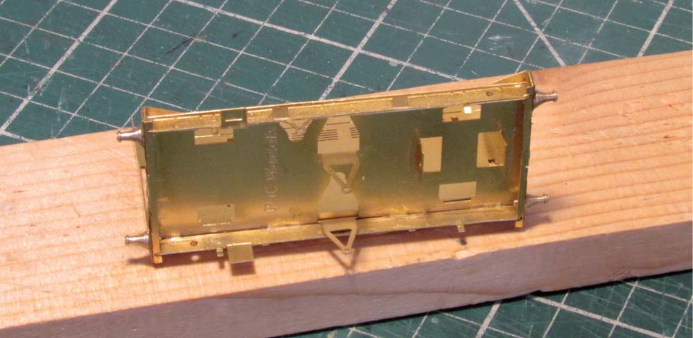
Fig. 72 The model is built as a series of layers, beginning with the underframe folded up. The sole bar overlays are added and the buffer beam and buffer shanks fixed in position.
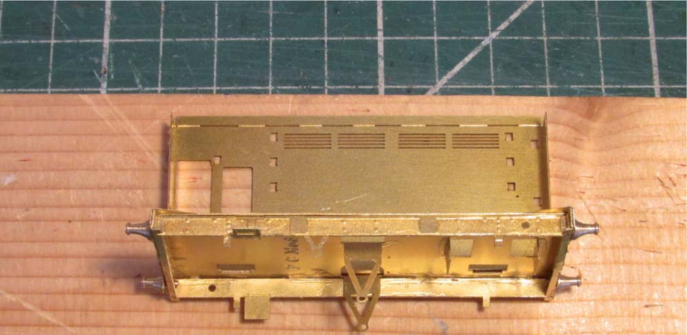
Fig. 73 The inner sidewalls are added to the underframe starting with one long side and then working around the body to form a complete a box structure.
Fig. 74 The outer sidewalls and the details to the end walls are then added to complete the body. On this model waste brass strips from the fret were used to form additional ballast weight to fix inside the wagon body.
The key point when fixing the sides together is that the lower tab, bent at 90 degrees, sits on the chassis and slots over the protruding tabs from the sole bar inner. So it is important to make sure that your solder or glue does not flow around the top edges of the tabs protruding through the flow through the floor, otherwise you will have to clean them up to remove excess materials to enable the sides to sit flush on the chassis.
I chose to add ballast to the wagon kit and fixed two brass strips across the middle of the wagon at this stage of the body construction, on which the ballast would be fixed later (see Fig. 74). The next stage of the process was to work on the construction of the underframe detail. When folding up the ‘W’ irons and clasp brake sub-assemblies for each axle (one rigid and one rocking), be aware of what type of coupling arrangement you wish to fit on to the completed wagon. I use tension lock couplings, so to ensure space for the coupler and mounting block, it was necessary to omit the outer brake block connecting bars and the safety loop.
From my experience, I would recommend that you work slowly and patiently on this type of kit. The parts fix together well, but you need to make sure that you put them together in the correct sequence. As I have noted previously, use dry runs to test fit and work out the best sequence of construction. During the construction of the underframe details, check fitting and running of the wheels regularly; I found the need to make small adjustments to the brake gear and safety loops.
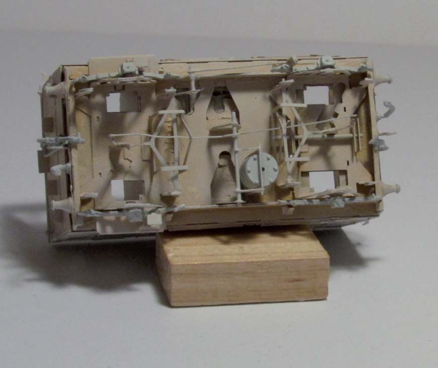
Fig. 75 A view of the underside of the completed wagon after application of primer, showing rocking compensation unit to the right-hand side of the image. The underframe detail has been added and the kit is awaiting matt black top coat for completion.
PAINTING YOUR MODELS
As well as considering the materials and tools required for kit or scratch building, it is also important to consider how you want to paint the completed model, as well as the application of appropriate decals. In this section I will consider some points on painting and provide some comments on decals in the following section.
WHEN TO DO THE PAINTING
The first question is whether to paint before or after construction, and the answer is not always the same. A review of the pros and cons of when to carry out painting has been presented in the table The Pros and Cons of Painting at Various Stages.
THE PROS AND CONS OF PAINTING AT VARIOUS STAGES
| Before Construction | |
| Pros | Cons |
● Easier to paint fine detail whilst parts are still on the sprues● Easier to hold sprue and paint detail without getting paint on other parts or details● Enables you to be able to paint internal or hard-to-access parts the right colour |
● Where the part is cut from the sprue, it will still need to be touched up with paint● You may need to sand joints and get clean edges on the components so that they will adhere and therefore the parts may need re-painting after the joint has set● Glue marks after construction will need to be touched up |
| After Construction | |
| Pros | Cons |
● Depending on the quality of mould, cast or etch, and your ability as a modeller, you may have to fettle joints or parts to fit together, and then paint to cover all this over● Cover up glue marks and joint lines with paint | ● Some fine detail parts are difficult or impossible to paint when the model has been put together |
The comments listed in the table suggest that the best compromise is to paint fine detail and internal components before and external parts after construction. This is where reading and understanding the instructions provided, before you do anything else, is important. If you understand how and when parts are assembled, this will let you identify which parts need painting before building and what can be left until the model is built, or at least largely built.
TYPES OF PAINT
The most common paints used for models are enamels and acrylics. The choice is down to individual choice and preference. Enamel paints are very common for all types of modelling in matt, satin and gloss finishes, and are readily available in a wide range of colours and shades (see Fig. 76). Enamel paints are hard-wearing and for railway modelling many of the railway company paint liveries have been replicated by a number of specialist paint suppliers of enamel paints.
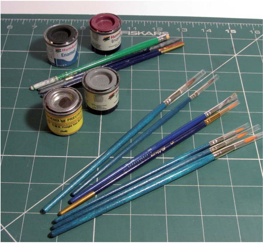
Fig. 76 A wide selection of enamel paints is available for the modeller produced by Humbrol, Phoenix and others. Phoenix produce paints to match numerous railway company liveries. A variety of fine brushes is useful for painting your completed model.
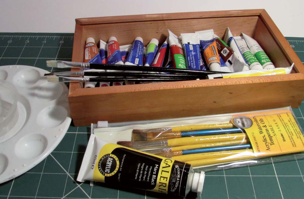
Fig. 77 To bring out fine detail and add weathering effects, it is possible to use a selection of good quality acrylic paints with suitable brushes and mixing palette.
Acrylic paints (see Fig. 77) are also available in a wide spectrum of colours and can easily be blended to produce just about any shade or colour required. Being water-based, I have found that acrylic paints are less hard-wearing, but being relatively quick drying they are excellent for weathering and dry brushing techniques. I tend to use enamel paints for the base colour coats and then sometimes use acrylic paints to highlight details or provide light weathering.
HAND PAINTING OR AIR BRUSHES
I do all my painting by hand with a selection of brushes, with the exception of the use of aerosol paints (generally car body spray paints), which I often use to prime metal components prior to painting. I am pleased with the quality of painting that I achieve by hand painting. It is also possible to achieve excellent finish quality using air brushes. On a personal level, I have always been put off by the cost of an air brush and compressor in the past and have stuck with my tried and tested hand-painting techniques. It is essential for hand painting that one uses good quality brushes and that the brushes are thoroughly cleaned straight after each painting session.
The cost of air brushes and the range available today is considerable and prices have reduced in relative terms as a result of the increasing availability and ranges on offer. However, I have not yet been tempted to have a go, as I still prefer the hand-painting techniques I have honed building all types of kits over the last thirty years or more. I am sure there will be many readers who will have an equally strong preference for the use of air brushes and the quality of finishes that they can achieve using these tools. At the end of the day, it is down to personal preferences and circumstances.
My advice to a beginner would be to try kit building and use the relatively cheap option of a paint brush first. If you decide to develop kit and scratch building as an area of your railway modelling, then consider investing in an air brush and associated equipment.
APPLICATION OF DECALS
On completion of the painting of your model, the final finishing touch is to add the decals appropriate to the railway company or private owner and period being modelled.
The application of decals is an area where there is likely to be some debate. Many of the kits available today at the less expensive and more straightforward to build end of the market often come with waterslide decals. Generally these decals include the basic company letter, load, tare and a selection of running from which to choose. The more complicated kits for the more experienced modeller tend not to include the decals, leaving it up to the individual to decide on the type and style of decals, based on the time period and area being modelled.
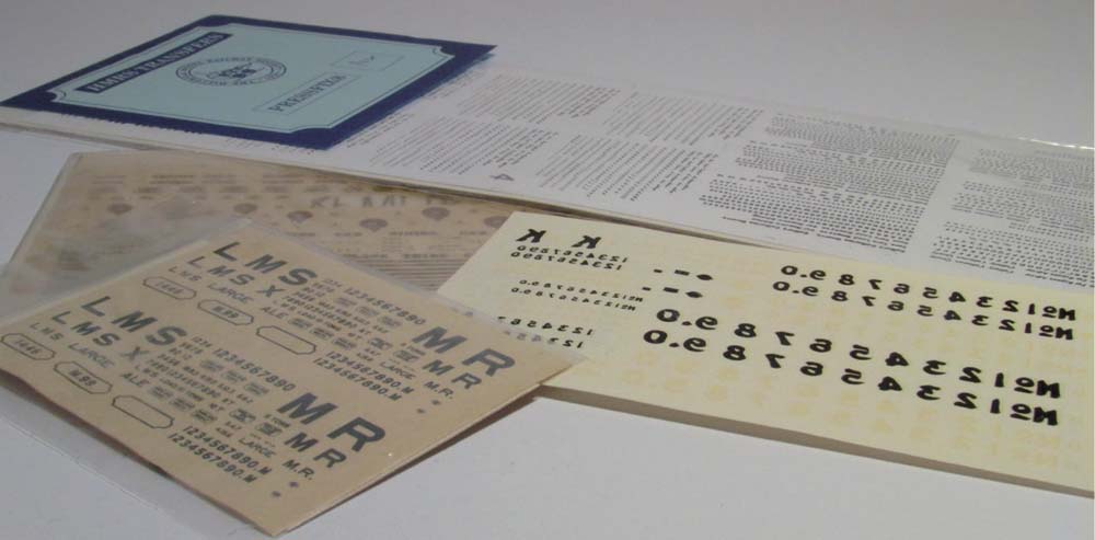
Fig. 78 To complete the model rolling stock, a selection of Pressfix (produced by HMRS) and/ or waterslide decals can be used for company or owner details.
More detailed and expansive sheets of decals are available to the modeller from a number of commercial sources and generally fall in to three main categories: waterslide, Pressfix and Methfix. Out of preference, having used all three types, I prefer to use Pressfix decals and tend to use the sheets available from the Historical Model Railway Society (HMRS), unless it is something highly specialized, for which I may use waterslide decals from suppliers such as Modelmaster Decals or Fox Transfers.
Decal application instructions seem to vary by supplier and, as with kit instructions, it is advisable to read through any instructions before starting work on the kit. For my preferred Pressfix decals, I have a few simple tools that I have to hand when applying decals to my models and would recommend the same:
I use a fine scalpel to score around each decal on the front paper and then to carefully separate the front from the backing paper. I always use tweezers to peel off each loosened decal and to place the decal in the desired position on the model. Using a combination of the scalpel and tweezers enables me to fine tune the placement to try and get it exactly correct, with reference to the photographs of the prototype, as discussed elsewhere.
The plastic right angle is used to ensure that the positioning of the decals is square and perpendicular to the base of the wagon, where necessary. It is also useful as a straight edge when positioning numbers or text to ensure that all the individual numbers and letters are aligned.
The old paint brush is used to apply water to the back of the decal once positioned and for fine movement to correct the alignment. Once the backing paper has thoroughly soaked through, the brush is used to remove the backing paper from the decal and to flood the area with water to remove surplus adhesive. The tissue or absorbent cloth is used to mop up the water and press the decal firmly on to the model to ensure that it affixes. I use my finger nail to run gently over the decals where these extend over planking or strapping detail on the wagon body to ensure the decal fits to the contours of the body.
The last element noted above is patience – this is extremely important when fixing lots of decals on your finished model. Do not be tempted to rush, as a crooked line of decals will be obvious on a completed model and it would be a shame to have to scrape off the decals and start again.