5.2 Collaboration Profiles
During an exchange of messages between different parties, it’s important to be able to label the different entities with an identifier to facilitate the readability of the interface configured in SAP PO.
As the name states, collaboration profiles represent a set of Integration Directory artifacts used to identify and designate the parties and systems involved in an integration scenario. This is irrespective of whether they play the role of sender or receiver in the scenario, which means that the party either sends or receives a message from SAP PO. The collaboration profiles help to uniquely identify an application system or organization taking part in an integration scenario.
The communication profile is made up of artifacts comprising party, communication component (business system and business component), and communication channels. Each of those artifacts will be explored in the following sections.
5.2.1 Party
A party is generally used as an identifier for an organization. If your organization exchanges messages with external companies or business partners, consider using a party to represent the external organization. Parties therefore are mostly used in business-to-business (B2B) scenarios. They represent a higher level of abstraction and a grouping of the real applications participating in a communication. You don’t need a party for your own organization; you can instead directly define the communication component without a party.
When naming the party, use a name that is meaningful and represents the actual organization that you’re dealing with (e.g., Coca-Cola). You can use internationally recognized identifiers (or alternative identifiers) to guarantee that the party is uniquely identified.
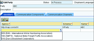
As indicated in Figure 5.3, you can choose the type of unique identifier to be used from the Agency field. You can choose from among the following identifiers:
- 009 (EAN - International Article Numbering Association)
- 166 (NMFTA - National Motor Freight Traffic Association)
- 016 (Dun & Bradstreet Corporation)
Figure 5.3 Alternative Identifier Options for a Party in the Integration Directory
After selecting an agency identifier, the Scheme field will be automatically filled in. Then, the only remaining action is to manually enter the actual unique identifier “ID” (for Integration Directory) under the Name field. You’ll need to get the identifier of the company from the relevant agency, based on the chosen agency.
Note
You can also attach communication components under a party.
5.2.2 Communication Component
A communication component represents the real application system involved in an exchange of messages. We can distinguish two main types of communication components: business systems and business components. We’ll explore each of those now.
Business System
A business system is created in the SLD and is linked to a technical system in your landscape. When the real application system (of types SAP NetWeaver AS ABAP, SAP NetWeaver AS Java, standalone, or third party) exists in your landscape, it should be considered a business system.
A business system can’t be created in the Integration Directory, but you can import it from the SLD by following these steps:
- Right-click on the left panel or on Communication Components Without Party, and select Assign Business System.
- Follow the wizard, and you’ll be presented with a list of all the business systems present in the SLD (but not yet imported into the Integration Directory).
- Select the business system(s) that you would like to import into the Integration Directory, and click on Finish.
- The business system(s) are created, added to a change list, and visible in the Integration Directory.
When you’re finished, the created business systems will have an orange circle around them to indicate that they aren’t yet activated and are thus invisible to other developers.
Because the business system is defined in the SLD, the type of service interface (message) it can send or receive is controlled and defined from the SLD. While doing the configuration, if you want to be able to select a service interface from a business system, then make sure that the technical system related to the business system in question is linked to the software component (SC) under which the service interfaces are located. This notion of linking the technical system to the relevant SCs was explained in more detail in Chapter 3.
Business Component
A business component can be used to label a virtual business system, which needs to be used in an exchange of messages. The word “virtual” is used here to indicate that it doesn’t need to be a physical system in your landscape. It can simply be a logical grouping unit or any other part of your landscape that you would like to label as a logical unit. It can, for instance, be handy to represent an SAP Business Process Management (SAP BPM) process.
Note
A business component doesn’t exist in the SLD and can manually and locally be created in the Integration Builder. After you’ve manually added the business component to the Integration Builder, you need to attach service interfaces (outbound and inbound) to it, which can be used to send and receive messages.
To create a new business component in the Integration Directory, follow these steps:
- If you want to create the business component as part of a party, then first create the party, and navigate to its communication component (as explained in Section 5.2.1). Then, proceed to step 3.
- If the business component belongs to your organization and not to an external party, then expand the arrow next to the communication component without a party, as can be seen next to the party named ABC in Figure 5.2.
- Right-click on the business component and select New.
- Specify the desired name in the Communication Component field.
After successfully creating a business component, you’ll need to maintain outbound service interfaces (under the Sender tab) and inbound service interfaces (under the Receiver tab). Without this step, you won’t be able to configure interface flows based on the concerned service interface and newly created business component.
To add a service interface under a Sender or Receiver tab of the business component, follow these steps:
- Open the business component.
- Open the Sender tab.
- Insert a new row, and assign the outbound service interfaces that you want the business component to be able to send.
- Open the Receiver tab.
- Insert a new row, and assign the inbound service interfaces that you want the business component to be able to receive.
- Save and activate.
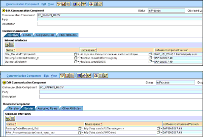
See Figure 5.4 for an example of what the business component looks like after you’ve added the needed service interfaces to the Sender and Receiver tabs.
Figure 5.4 Added Service Interfaces (Inbound and Outbound) in the Business Component
5.2.3 Communication Channel
A communication channel can be created for a business system or business component and represents a connection from or to a particular system. When creating a communication channel, you need to provide a unique (and preferably meaningful) name.
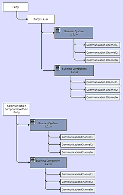
Figure 5.5 depicts the different objects in the Collaboration Profile area and how they relate to each other. You can see that business systems and business components can be created under a party (if they are external systems) or within the Communication Component Without Party area. Both business systems and components can contain an unlimited number of channels.
A communication channel has a number of attributes and properties, which we’ll explore in Section 5.3.
Figure 5.5 Collaboration Profile Tree
In addition, a communication channel needs to be linked to a communication component (business system or business component). Its name needs to be unique within the communication component to which it belongs. The communication channel contains three main tabs: Parameters, Identifiers, and Modules. These tabs are discussed in the following sections.
Parameters
The Parameters tab mostly contains specific attributes that relate to the adapter used, as follows:
-
Adapter Type
In this attribute, you select the type of adapter that you need for this specific communication. You can make a selection from a dropdown containing a list of SAP standard adapters. Adapter types from third-party providers (or your own custom adapter) and those that are installed in your system will also be selectable from this list. This adapter list is pulled from the ES Repository in an SAP Basis software component and the http://sap.com/xi/XI/System namespace.
Note that the adapter type might have a different version, depending on the version of SAP PO you’re running. More details on the different adapter types will be provided in Section 5.3. -
Direction
A direction helps to specify whether the connection is used by a sender or receiver system. You can distinguish between sender and receiver channels. Depending on the communication protocol used, a sender communication channel will behave differently from a receiver communication channel. To illustrate, a communication channel reading a file (sender channel) from a file system will contain details such as the directory in which the file is contained, the file name, and the polling interval. In contrast, a communication channel that writes a file (receiver channel) to a file system also needs the folder to write to and the file name but doesn’t need a polling interval.
A sender channel deals with how to convert an incoming message (from an external system) from another format into a format internally used in SAP PO or SAP PI. A receiver channel deals with converting a message from the SAP PO-specific format or SAP PI-specific format into a format expected by the receiver system. This SAP PO or SAP PI internal format is also referred to as the XI message protocol, which is covered in Section 5.5. -
Transport Protocol
Depending on the chosen adapter type, you might be given a choice of different transport protocols. Some common transport protocol choices include HTTP 1.1 and HTTPS. The file adapter, for instance, provides Network File System (NFS) and File Transfer Protocol (FTP) as options. -
Message Protocol
The message protocol choices also depend on the adapter type that you selected. -
Adapter Engine
This attribute gives you the chance to specify under which adapter engine the channel needs to run. This is very useful if your SAP PO installation operates together with some decentralized adapter engines. You then can choose among the different adapter engines via a dropdown list. If you don’t have a decentralized adapter engine, then the default adapter engine will be selected for you by default.
Note
A decentralized adapter engine runs as a standalone engine and provides a totally independent runtime environment. Using a decentralized adapter engine can improve your performance, decrease processing time, and provide runtime isolation.
Identifiers
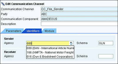
Identifiers are relevant in cases when a party is involved. As indicated in Section 5.2.1, it’s possible to specify various identifiers to uniquely identify the party. When multiple identifiers are used in a party, the communication channel’s Identifiers tab enables you to choose which one of the existing identifiers is to be used for this specific communication channel. You can use a dropdown list to select the appropriate agency (see Figure 5.6).
Figure 5.6 Choosing an Identifier in the Communication Channel
Module
This tab enables you to choose the different adapter modules to be executed during runtime. Each module entry in the communication channel is also referred to as a module processor. When a new communication channel is created, it comes with some default modules, depending on the chosen adapter type. The following are a few of the default modules:
-
CallSapAdapter
Mostly present as the first module for the file, Simple Object Access Protocol (SOAP) sender, and Java Database Connectivity (JDBC) adapters. -
sap.com/com.sap.aii.af.soapadapter/XISOAPAdapterBean
Used for the receiver SOAP adapter. -
sap.com/com.sap.aii.adapter.mail.app/XIMailAdapterBean
Used for the mail adapter. -
RfcAFBean
Used for the Remote Function Call (RFC) adapter.
Note
Note that a SOAP adapter (with HTTP) is restricted and can’t easily be extended with extra adapter modules. You’ll need to use one of the Apache extensible Interaction System (Axis) transport protocol variants to extend it.
In addition to the modules just listed, SAP delivers an additional set of modules by default with an SAP PO installation. See Table 5.1 for a list of some default modules delivered with the adapter framework and their uses.
Table 5.1 List of SAP Standard Modules and Their Uses
These modules can’t be selected from the tab; instead, you’ll need to manually enter the name of the module in the Module name field. Names of modules delivered with the adapter framework by SAP are always preceded with the prefix AF_Modules/. For example, to use XMLAnonymizerBean, you’ll need to use the module name AF_Modules/XMLAnonymizerBean.
In addition, make sure to choose the Local Enterprise Bean value in the Type dropdown list. You can add as many adapter modules as you need. They will be processed in a sequential order, and the output of one will become the input of the following one.
If you intend to extend the configuration of your communication channel with a list of adapter modules (custom modules or SAP-delivered ones), then it’s important to place them in the right sequence and position in the module processor. The decision of where to place your module will depend on the following factors:
- Whether your communication channel will be supporting a synchronous or asynchronous interface
- Whether it’s a sender or receiver channel
- Which message protocol is used in the channel
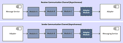
For asynchronous processing, the adapter module is always placed at the end of the chain. For a receiver channel, it’s important to first place any other module (customer or provided by SAP). In Figure 5.7, these other modules are represented by modules A, B, and C. Place the adapter module (the adapter module box with the dashed line in the figure) at the end of the chain and just before the adapter
In the case of a sender channel, start by placing all other modules, and leave the adapter module for the end—just before the messaging service.
Figure 5.7 Adapter Module Processor for an Asynchronous Sender and Receiver Channel
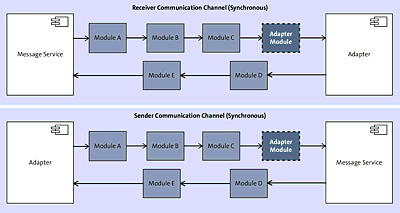
For synchronous processing, the same rules apply as for the asynchronous communication. The only difference is that you can place more adapter modules (customer or provided by SAP) after the adapter to handle the response message. As such, all modules before the adapter module will apply to the request message, and the ones after the adapter will affect the response message. Figure 5.8 shows different possibilities of places to position the module, depending on whether it’s a sender or receiver channel.
Figure 5.8 Adapter Module Processor and Appropriate Position of Modules for Synchronous Sender and Receiver Channel
For every configured module, you can also add module parameters at the bottom, in the Module Configuration area of the screen.
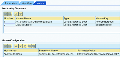
See Figure 5.9 for an example of the configuration of the XMLAnonymizerBean module. The XMLAnonymizerBean is placed before the adapter module (CallSapAdapter). The module is configured as follows:
-
Processing Sequence:
- Module Name: AF_Modules/XMLAnonymizerBean
- Type: Local Enterprise Bean
- Module Key: “AnonymizerBean” (You can give it any module key name.)
-
Module Configuration:
- Module Key: AnonymizerBean (This needs to match the one chosen in the Processing Sequence area; you can select it from the dropdown.)
- Parameter Name: “anonymizer.acceptNamespaces”
- Parameter Value: “http://rojoconsultancy.com/demo/book''
Figure 5.9 Example of XMLAnonymizerBean Configuration
The following statements apply to this module:
- In some scenarios, you might be required to change the namespace prefix to a specific value. The module is used to change the namespace’s prefix of the incoming XML message to another prefix value.
- In the Parameter Value section, you need to specify the namespace and the prefix to be keep. All other namespaces and prefixes that aren’t specified will be removed.
- The namespace and the prefix are separated with a space.
- If you don’t want a prefix to be present in your output message, use two single quotes ('') as a prefix.
- You can specify multiple namespaces and prefixes.
- If the module is used without the anonymizer.acceptNamespaces parameter, then all the namespaces in the incoming message will be removed.
All other namespaces and prefixes found in the message that aren’t in the preceding list will be removed.
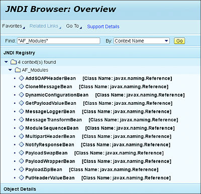
In the example shown in Figure 5.10, the prefix associated with the namespace http://rojoconsultancy.com/demo/book in the incoming XML message will be removed.
Figure 5.10 JNDI Browser: Overview Screen
As time passes and new versions of SAP PO are released, the number of modules delivered with the adapter framework will probably increase. You can use the Java Naming and Directory Interface (JNDI) to confirm or discover the modules that have been deployed as part of the adapter framework on your SAP PO installation. To do that, follow these steps:
- Log in to the SAP NetWeaver Administrator via http://<hostname>:<port>/nwa, where <hostname> is the hostname of the SAP NetWeaver system, and <port> is the port number of the SAP NetWeaver system.
- Navigate to Troubleshooting • Java, and then click on the JNDI Browser link.
- On the next screen, enter “AF_Modules” in the Find field. Then, select Context Name from the dropdown of the By field. Click on the Go button.
- You’ll see the results of your search. You need to collapse the AF_Modules result because the adapters delivered with the adapter framework start with the AF_Modules prefix in front of their actual names. Refer to Figure 5.10 as a reference for what the JNDI Browser: Overview screen looks like.
Note that even though a comprehensive number of adapter modules are available, you might come across requirements that aren’t supported with the currently existing set of modules. Luckily, you can create your own custom adapter modules. Given that the adapter engine and framework is based on the SAP NetWeaver AS Java, you’ll need a basic knowledge of Java to successfully implement your own additional functionality. To facilitate your Java development, you’ll need to make use of the SAP NetWeaver Developer Studio as the development tool.
Developing a custom module adapter for SAP PO is beyond the scope of this chapter, but it is possible.
5.2.4 Communication Component without a Party
The decision to choose whether to create a party or a communication component without a party depends on your answer to the following question: Is the application system in question part of your organization or an external organization?
If the application is part of your organization, then use a communication component without a party. Otherwise, use a party. You don’t have to stick to this approach, but we believe it’s a good way to keep things separate and to easily identify when you’re dealing with external systems.
ASMAs are attributes that provide extra information about messages. This information isn’t part of the message’s payload, but rather is included as header data. Depending on the adapter used, SAP provides the ability to read and write these message header data/attributes. These attributes are different for each adapter type. The details of the attributes available for each adapter can be accessed in the SAP BASIS SC and the http://sap.com/xi/XI/System namespace. You can look it up in the ES Repository.
The attributes are placed under the corresponding adapter type, so to access any attribute related to the file adapter you’ll need to use the http://sap.com/xi/XI/System/File namespace. For the JMS-specific adapter attributes, use the http://sap.com/xi/XI/System/JMS namespace.
Some of the attributes of the file adapter include the following:
- FileName
- FileEncoding
- Directory
- FileType
- SourceFileSize
- SourceFileTimeStamp
- SourceFTPHost
These attributes can be accessed and manipulated from the mapping by using a user-defined function (UDF). An example of a UDF to overwrite the value in the filename attribute of the file adapter is provided in Listing 5.1.
DynamicConfiguration conf = (DynamicConfiguration) container.getTransformationParameters().
   get(StreamTransformationConstants.DYNAMIC_CONFIGURATION);
DynamicConfigurationKey fileName = DynamicConfigurationKey.
   create("http://sap.com/xi/XI/System/File","FileName");
conf.put(FileName, "foo.txt");
Listing 5.1 UDF to Overwrite the Value of the Filename Attribute of the File Adapter
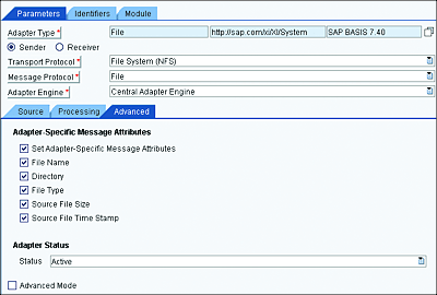
To make the new overwritten filename value affect your communication (receiver), you’ll need to activate the ASMA on the communication channel. Doing so will make the receiver communication channel use the new value of the filename attribute to write the file. To do this, follow these steps:
- Open the communication channel (sender or receiver) in question.
- On the Advanced tab, select the Set Adapter-Specific Message Attributes. See Figure 5.11 for a communication channel configuration example.
Figure 5.11 The Adapter-Specific Message Attributes Enabled in the Communication Channel
After activating the Set Adapter-Specific Message Attributes checkbox, all the attributes selected will be available in the dynamic configuration and can be read and modified. The dynamic configuration can then be used to change the name of the file to be written in a receiver communication channel.
As a result of activating the ASMA (see Figure 5.12), the dynamic configuration now contains details about the file name, file size, file type, directory, and timestamp of the file, which were picked up by the file communication channel.
Figure 5.12 Impact of Activating the ASMA on the Dynamic Configuration
