Working with resistors in series, parallel, and combination
Creating a voltage-divider circuit
Looking at how a potentiometer varies resistance
My favorite science fiction villains are the Borg from Star Trek: The Next Generation.
They had a saying: “Resistance is futile.”
In the Star Trek
world, it turned out that resistance against the Borg wasn’t futile. Picard and the rest of the crew of the Enterprise
resisted and eventually triumphed over the Borg.
In the electronics world, resistance is not futile. In fact, resistance can be very useful. Without resistance, electronics would not be possible. Electronics is all about manipulating the flow of current, and one of the most basic ways to manipulate current is to reduce it through resistance. Without resistance, current would flow unregulated and there would be no way to coax it into doing useful work.
In this chapter, you learn what resistance is and how to work with resistors,
which are little devices that let you intentionally introduce resistance into your circuits. You also learn about a fundamental relationship in the nature of electricity: the relationship between voltage, current, and resistance. This relationship is expressed in a simple mathematical formula called Ohm’s law.
(Not to worry; the
math isn’t complicated. If you know how to multiply and divide, you can understand Ohm’s law.) And finally, you learn the most common ways resistors are used in circuits.
What Is Resistance?
As you already know, a conductor
is a material that allows current to flow, and an insulator
is a material that doesn’t. Good conductors allow current to flow with abandon, without impediments. Examples of good conductors include the metals copper and aluminum. Carbon is also an excellent conductor. Good insulators, on the other hand, erect solid walls that completely block current. Examples of good insulators include glass, Teflon, and plastic. The key factor that determines whether a material is a conductor or an insulator is how readily its atoms give up electrons to move charge along. Most atoms are very possessive of their electrons, and are therefore good insulators. But some atoms don’t have a strong hold on their outermost electrons. Those atoms are good conductors.
If a conductor and an insulator are mixed together, the result is a compound that conducts current, but not very well. Such a compound has resistance —
that is, it resists the flow of current. The degree to which the compound resists current depends on the exact mix of elements that make up the compound.
For example, a conducting material such as carbon might be mixed with an insulating material such as ceramic. If the mix is mostly carbon, the overall resistance of the mixture will be low. If the mix is mostly ceramic, the overall resistance will be high.
The truth is, all
materials have some resistance. Even the best conductors have a small but measurable amount of resistance. The only exceptions are certain materials called superconductors
that, when chilled to unbelievably low temperatures, conduct with 100 percent efficiency. Unfortunately, you can’t buy superconductors at RadioShack, and even if you could, you can’t buy a freezer at Sears powerful enough to chill the stuff down to absolute zero.
Measuring Resistance
Resistance is measured in units called ohms,
represented by the Greek letter omega (
). The standard definition of one ohm
is simple: It’s the amount of resistance required to allow one ampere of current to flow when one volt of potential is
applied to the circuit. In other words, if you connect a one-ohm resistor across the terminals of a one-volt battery, one amp of current will flow through the resistor.
A single ohm (
) is actually a very small amount of resistance. Resistances in the hundreds, thousands, or even millions of ohms are usually called for in electronic circuits.
In Book 1, Chapter 8
, you learn that you can measure resistance of a circuit using an ohmmeter,
which is a standard feature found in most multimeters. The procedure is simple: First, you disconnect all voltage sources from the circuit; then, you touch the ohmmeter’s two probes to the ends of the circuit and read the resistance (in ohms) on the meter.
Here are a few other points to consider about resistance and ohms:
The abbreviations k
(for kilo
) and M (for mega
) are used for thousands and millions of ohms. Thus, a 1,000-ohm resistance is written as
, and a 1,000,000-ohm resistance is written as
.
For the purposes of most electronic circuits, you can assume that the resistance value of ordinary wire is zero ohms (
). In reality, however, only superconductors have a resistance of
. Even copper wire has some resistance. Because of that, the resistance of wire is usually measured in terms of ohms per kilometer or per mile. Electronic circuits usually deal with wires that are at most a few inches or feet long, not kilometers or miles.
Short circuits also have essentially zero resistance.
Just as ordinary wire and short circuits can be considered to have zero resistance, insulators and open circuits can be considered to have infinite resistance, and in reality, there’s no such thing as completely infinite resistance. If you connect two wires to the terminals of a battery and hold the wires apart, a voltage difference exists between the ends of those two wires, and a very small current will travel between them — even through the air because air doesn’t have infinite resistance. This current is extraordinarily small — too small to even measure — but it’s there nonetheless. Electric currents are literally everywhere.
The unit ohm
is named after the famous German physicist Georg Ohm,
who was the first to explain the relationship between voltage, current, and resistance in 1827.
Actually, the discovery was first made by a British scientist named Henry Cavendish more than 45 years earlier, but Cavendish never published his work. If he had, resistance would be measured in cavens, not ohms.
Looking at Ohm’s Law
The term Ohm’s law
refers to one of the fundamental relationships found in electric circuits: that, for a given resistance, current is directly proportional to voltage. In other words, if you increase the voltage through a circuit whose resistance is fixed, the current goes up. If you decrease the voltage, the current goes down.
Ohm’s law expresses this relationship as a simple mathematical formula:
In this formula, V
stands for voltage (in volts), I
stands for current (in amperes), and R
stands for resistance (in ohms). (You may be wondering why V
stands for voltage here, but in other equations voltage is sometimes represented by the letter E
. Although scientists sometimes argue over whether V or E should be used in various circumstances, for the most part V and E are interchangeable when referring to voltage.)
Here’s an example of how to calculate voltage in a circuit with a lamp powered by the two AA cells. Suppose you already know that the resistance of the lamp is
, and the current flowing through the lamp is 250 mA, which is the same as 0.25 A. Then, you can calculate the voltage as follows:
Ohm’s law is incredibly useful because it lets you calculate an unknown voltage, current, or resistance. In short, if you know two of these three quantities you can calculate the third.
Go back (if you dare) to your high-school algebra class and remember that you can rearrange the terms in a simple formula such as Ohm’s law to create other equivalent formulas. In particular:
If you don’t know the voltage, you can calculate it by multiplying the current by the resistance:
If you don’t know the current, you can calculate it by dividing the voltage by the resistance:
If you don’t know the resistance, you can calculate it by dividing the voltage by the current:
To convince yourself that these formulas work, look again at the circuit with a lamp that has
of resistance connected to two AA batteries for a total voltage of 3 V. Then you can calculate that the current flowing through the lamp is 0.25 A (or 250 mA), as follows:
If you know the battery voltage (3 V) and the current (250 mA, which is 0.25 A), you can calculate that the resistance of the lamp is
, like this:
Wasn’t going back to high school algebra fun? Next thing you know, you’re going to start looking for a prom date.
The most important thing to remember about Ohm’s law is that you must always do the calculations in terms of volts, amperes, and ohms. For example, if you measure the current in milliamps (which you usually will in electronic circuits), you must convert the milliamps to amperes by dividing by 1,000. For example, 250 mA is 0.25 A.
Here are a few other things you should keep in mind concerning Ohm’s law:
Remember how I say in the preceding section that the definition of one ohm is the amount of resistance that allows one ampere of current to flow when one volt of potential is applied to it? This definition is based on Ohm’s law. If V
is 1 and I
is 1, then R
must also be 1.
If you wonder why the symbols for voltage and resistance are V
and R
, which make perfect sense, but the symbol for current is I
, which makes no sense, it has to do with history. The unit of measure for current — the ampere — is named after André-Marie Ampère, a French physicist who was one of the pioneers of early electrical science. The French word he used to describe the strength of an electric current was intensité
– in English, intensity.
Thus, amperage is a measure of the intensity of the current. Hence the letter I.
In the interest of international cooperation, the term volt
is named for the Italian scientist Alessandro Volta, who invented the first electric battery in 1800. (Actually, his full name was Count Alessandro Giuseppe Antonio Anastasio Volta. But that won’t be on the test.)
Introducing Resistors
A resistor
is a component that’s designed to provide a specific amount of resistance in a circuit. Because resistance is an essential element of nearly every electronic circuit, you’ll use resistors in just about every circuit that you build.
Although resistors come in a variety of sizes and shapes, the most common type of resistor for hobby electronics is the carbon film resistor,
shown in Figure 2-1
. These small resistors consist of a layer of carbon laid down on an insulating material and contained in a small cylinder, with wire leads attached to both ends. The resistor itself is about
inch long, and the leads are about an inch long, making the entire thing about
inches long.
Resistors are blind to the polarity in a circuit. Thus, you don’t have to worry about installing them backwards. Current can pass equally through a resistor in either direction.
In schematic diagrams, a resistor is represented by a jagged line, like the one shown in the margin. The resistance value is typically written next to the resistor symbol. In addition, an identifier such as R1 or R2 is also sometimes written next to the symbol.
In some schematics, particularly those drawn in Europe, the symbol shown in the margin is used instead of the jagged line.
Resistors are used for many reasons in electronic circuits. The three most popular are
Limiting current:
By introducing resistance into a circuit, resistors can limit the amount of current that flows through the circuit. In accordance with Ohm’s law, if the voltage in a circuit remains the same, the current will decrease if you increase the resistance.
Many electronic components have an appetite for current that must be regulated by resistors. One of the best known are light-emitting diodes (LEDs), which are a special type of diode that emits visible light when current runs through it. Unfortunately, LEDs don’t know when to step away from the table when it comes to consuming current. That’s because they have very little internal resistance. Unfortunately, LEDs don’t have much tolerance for current, so too much current will burn them out. As a result, it’s always prudent — essential, in fact — to place a resistor in series with an LED to keep the LED from burning itself up. (You can learn more about LEDs in Chapter 5
of this minibook.)
You can use Ohm’s law to your advantage when using current-limiting resistors. For example, if you know what the supply voltage is and you know how much current you need, you can use Ohm’s law to determine the right resistor to use for the circuit as explained in the preceding section.
Dividing voltage:
You can also use resistors to reduce voltage to a level that’s appropriate for specific parts of your circuit. For example, suppose your circuit is powered by a 3 V battery but a part of your circuit needs 1.5 V. You could use two resistors of equal value to split this voltage in half, yielding 1.5 V. For more information, see the section “Dividing Voltage
,” later in this chapter.
Resistor/capacitor networks:
Resistors can be used in combination with capacitors for a variety of interesting purposes. You learn about this use of resistors in Chapter 3
of this minibook.
Reading Resistor Color Codes
You can determine the resistance provided by a resistor by examining the color codes
that are painted on the resistor. These little stripes of bright colors indicate two important factoids about the resistor: its resistance in ohms and its tolerance,
which indicates how close to the indicated resistance value the resistor actually is.
Most resistors have four stripes of color. The first three stripes indicate the resistance value, and the fourth stripe indicates the tolerance. Some resistors have five stripes of color, with four representing the resistance value and the last one the tolerance.
If you’re uncertain from which side of the resistor to read the colors, start with the side closest to the color stripe. The first stripe is usually painted very close to the edge of the resistor; the last stripe isn’t as close to the edge.
Reading a resistor’s value
To read a resistor’s color code, refer to Table 2-1
. Here’s the procedure for determining the value of a resistor with four stripes:
Orient the resistor so you can read the stripes properly.
You should read the stripes from left to right. The first stripe is the one that’s closest to one end of the resistor. If this stripe is on the right side of the resistor, turn the resistor around so the first stripe is on the left.
Look up the color of the first stripe to determine the value of the first digit.
For example, if the first stripe is yellow, the first digit is 4.
Look up the color of the second stripe to determine the value of the second digit.
For example, if the first stripe is violet, the second digit is 7.
Look up the color of the third stripe to determine the multiplier.
For example, if the third stripe is brown, the multiplier is 10.
Multiply the two-digit value by the multiplier to determine the resistor’s value.
For example, 47 times 10 is 470. Thus, a yellow-violet-brown resistor is
.
TABLE 2-1
Resistor Color Codes (Resistance Values)
Color
Digit
Multiplier
Black
0
1
Brown
1
10
Red
2
100
Orange
3
1 k
Yellow
4
10 k
Green
5
100 k
Blue
6
1 M
Violet
7
10 M
Gray
8
100 M
White
9
1,000 M
Gold
0.1
Silver
0.01
If a resistor has five stripes, the first three stripes are the value digits, and the fourth stripe is the multiplier. The fifth stripe is the tolerance, as described in the next section.
Here are a few examples that should help you understand how to read resistor codes:
Color Stripes
Digit Values
Multiplier (in Ohms)
Resistor Value
Brown - black - brown
10
10
Brown - black - red
10
100
Red - red - orange
22
1 k
Red - red – yellow
22
10 k
Yellow - violet – black
47
0.1
Understanding resistor tolerance
The value indicated by the stripes painted on a resistor provides an estimate of the actual resistance. The exact resistance varies by a percentage that depends on the tolerance
factor of the resistor.
For example, a
resistor with a
percent tolerance actually has a value somewhere between 5 percent above and 5 percent below
, which works out to somewhere between
and
. A
resistor with a 10 percent tolerance has an actual value somewhere between
and
.
Why the approximations? Simply because it costs more money to manufacture resistors to very close tolerances, and for most electronic circuits, a 5 percent or 10 percent margin of error is perfectly acceptable. For example, if you’re building a circuit to limit the current flowing through a component to 200 mA, it probably won’t matter much if the actual current is a little above or below 200 mA. Thus, a 5 percent or 10 percent tolerance resistor is acceptable.
If your application demands higher precision, you can spend a bit more money to buy higher-tolerance resistors. But
percent or
percent tolerance resistors are fine for most work, including all the circuits presented in this book (unless otherwise indicated).
The tolerance of a resistor is indicated in the resistor’s last color stripe, as listed in Table 2-2
.
Resistors are like brakes for electric current. Like the brakes in your car, resistors work by applying the electrical equivalent of friction to flowing current. This friction inhibits the flow of current by absorbing some of the current’s energy and dissipating it in the form of heat. Whenever you use a resistor in a circuit, you must make sure that the resistor is capable of handling the heat.
The power rating
of a resistor indicates how much power a resistor can handle before it becomes too hot and burns up. You may remember from Book 1, Chapter 2
that power is measured in units called watts.
The more watts a resistor can handle, the larger and more expensive the resistor is.
Most resistors are designed to handle
W or
W. You can also find resistors rated for
W or 1 W, but they’re rarely needed in the types of electronic projects you build in this book. Unless otherwise stated, all the resistors used in this book are rated at
W.
Unfortunately, you can’t tell a resistor’s power rating just by looking at it. Unlike resistance and tolerance, there are no color codes for wattage. However, the size of the resistor is a good indicator of its power rating. Power ratings are written on the packaging when you buy new resistors. After you work with them for a while, you’ll come to quickly recognize the size difference between resistors of different power ratings.
If you want to be safe, you can calculate the power demands required of a particular resistor in your circuits. First, use Ohm’s law to calculate the voltage across the resistor and the current that will pass through the resistor. For example, if a
resistor will have 3 V across it, you can calculate that 30 mA of current will flow through the resistor by dividing the voltage by the resistance (
, which is 30 mA).
Once you know the voltage and the current, you can calculate the power that will be dissipated by the resistor by using the power formula you learn about back in Book 1, Chapter 2
:
Thus, the power dissipated by the resistor will be just 0.09 W, well under the maximum that can be handled by a
W (0.25 W) resistor. (A
W resistor should be able to handle this amount of power too, but it’s always better to err on the large side when it comes to power ratings.)
Limiting Current with a Resistor
One of the most common uses for resistors is to limit the current flowing through a component. Some components, such as light-emitting diodes, are very sensitive to current. A few milliamps of current is enough to make an LED glow; a few hundred milliamps is enough to destroy the LED.
Project 10 shows you how to build a simple circuit that demonstrates how a resistor can be used to limit current to an LED. The schematic diagram for this circuit is shown in Figure 2-2
.
Before we get into the construction of the circuit, here’s a simple question: Why a
resistor? Why not a larger or a smaller value? In other words, how do you determine what size resistor to use in a circuit like this?
The answer is simple: Ohm’s law, which can easily tell you what size resistor to use, but you must first know the voltage and current. In this case, the voltage is easy to figure out: You know that two AA batteries provide 3 V. To figure out the current, you just need to decide how much current is acceptable for your circuit. The technical specifications of the LED tell you how much current the LED can handle. In the case of a standard 5 mm red LED (the kind you can buy at RadioShack for about $1.50), the maximum allowable current is 28 mA. To be safe and make sure that you don’t destroy the LED with too much current, round the maximum current down to 25 mA.
To calculate the desired resistance, you divide the voltage (3 V) by the current (0.025 A). The result is
.
Do not
connect the LED directly to the battery without a resistor. If you do, the LED will flash brightly, and then it will be dead forever.
Project 10: Using a Current-Limiting Resistor
In this project, you build a simple circuit that uses a resistor to limit the current to an LED. Without this current-limiting resistor, too much current would flow through the LED and the LED would be destroyed.
The only tools you need for this project are perhaps a small Phillips-head screwdriver to open the battery holder, and wire cutters and strippers to cut and strip the jumper wire.
Parts
Two AA batteries
One battery holder (RadioShack 2700408)
One red LED, 5mm (RadioShack 2760209)
One solderless breadboard (RadioShack 2760003)
One 1-inch jumper wire
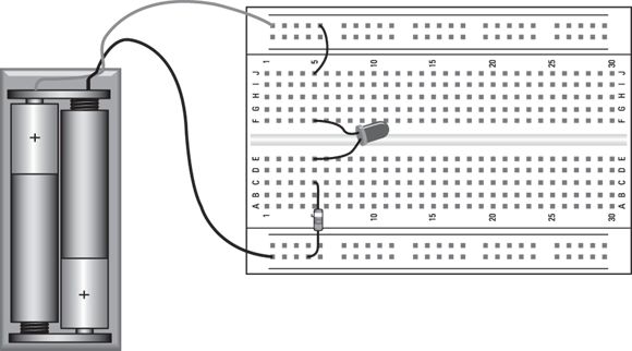
Steps
Connect the battery holder.
Orient the breadboard so that hole A1 is near the top left. Then, insert the black lead in the negative (–) bus strip on the left side of the breadboard and the red lead in the positive (+) bus strip on the right side of the breadboard.
Any location on the correct bus will be fine, but I recommend you insert the leads into the holes at the very end of the breadboard.
Connect the resistor.
Insert one end of the resistor into the breadboard in hole C5, and insert the other lead into any nearby hole in the positive voltage bus strip on the left side (the strip that’s connected to the red battery wire).
Connect the LED.
Notice that the leads of the LED aren’t the same length; one lead is shorter than the other. Insert the longer lead (called the anode
) into hole E5 and the shorter lead (called the cathode
) into hole F5.
Note that the circuit won’t work if you insert the LED backward.
Connect the short jumper wire to the LED to the negative bus.
Insert one end of the jumper in hole J5 and the other end in any hole on the negative bus at the right side of the breadboard.
Insert the batteries.
The LED lights up. If it doesn’t, double-check your connections to make sure the circuit is assembled correctly. If it still doesn’t light up, try a different battery.
Combining Resistors
Suppose you’ve designed the perfect circuit, and it calls for a
resistor in a critical spot. You run down to your local RadioShack and are miffed because you can’t find any
resistors. So you go online and search your favorite online suppliers and are even more miffed to discover that they don’t have
resistors either. You can buy
resistors and
resistors, but no one seems to have any
resistors.
Is it time to give up? Or must you settle for a
resistor and hope it will be close enough?
Certainly not!
All you have to do is use two or more resistors in combination to create the resistance that you need. Such a combination of resistors is sometimes called a resistor network.
You can freely substitute a resistor network for a single resistor whenever you want.
There are two basic ways to combine resistors: in series (strung end to end) and in parallel (side by side). The following sections explain how you calculate the total resistance of a network of resistors in series and in parallel.
You’ll need to put your thinking cap on when you read through the following sections. Ohm’s law is simple enough, but the math calculations required to calculate parallel resistors can get a little complex. The math isn’t horribly complicated, but it isn’t trivial, either.
Combining resistors in series
Calculating the total resistance for two or more resistors strung end to end — that is, in series — is simple: You simply add the resistance values to get the total resistance.
For example, if you need 1,100 ohms of resistance and can’t find an
resistor, you can combine a
resistor and a 100 Ω resistor in series. Adding these two resistances together gives you a total resistance of
.
You can place more than two resistors in series if you want. You just keep adding up all the resistances to get the total resistance value. For example, if you need
of resistance, you could use a
resistor and eight
resistors in series.
Figure 2-3
shows how serial resistors work. Here, the two circuits have identical resistances. The circuit on the left accomplishes the job with one resistor; the circuit on the right does it with three. Thus, the circuits are equivalent.
Any time you see two or more resistors in series in a circuit, you can substitute a single resistor whose value is the sum of the individual resistors. Similarly, any time you see a single resistor in a circuit, you can substitute two or more resistors in series as long as their values add up to the desired value.
The total resistance of resistors in series is always greater than the resistance of any of the individual resistors. That’s because each resistor adds its own resistance to the total.
Combining resistors in parallel
You can also combine resistors in parallel to create equivalent resistances. However, calculating the total resistance for resistors in parallel is a bit more complicated than calculating the resistance for resistors in series.
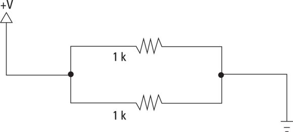
As the circuit shown in Figure 2-4
illustrates, when you combine two resistors in parallel, current can flow through both resistors at the same time. Although each resistor does its job to hold back the current, the total resistance of two resistors in parallel is always less than the resistance of either of the resistors because the current has two pathways through which to go.
So how do you calculate the total resistance for resistors in parallel? Very carefully. Here are the rules:
First, the simplest case: resistors of equal value in parallel. In this case, you can calculate the total resistance by dividing the value of one of the individual resistors by the number of resistors in parallel. For example, the total resistance of two,
resistors in parallel is
and the total resistance of four,
resistors is
.
Unfortunately, this is the only case that’s simple. The math when resistors in parallel have unequal values is more complicated.
If only two resistors of different values are involved, the calculation isn’t too bad:
In this formula, R1 and R2 are the values of the two resistors.
Here’s an example, based on a
and a
resistor in parallel:
For three or more resistors in parallel, the calculation begins to look like rocket science:
The dots at the end of the expression indicate that you keep adding up the reciprocals of the resistances for as many resistors as you have.
In case you’re crazy enough to actually want to do this kind of math, here’s an example for three resistors whose values are
,
, and
:
As you can see, the final result is
. That’s more precision than you could possibly want, so you can probably safely round it off to
, or maybe even
.
Mixing series and parallel resistors
Resistors can be combined to form complex networks in which some of the resistors are in series and others are in parallel. For example, Figure 2-5
shows a network of three,
resistors and one
resistor. These resistors are arranged in a mixture of serial and parallel connections.
The way to calculate the total resistance of a network like this is to divide and conquer. Look for simple series or parallel resistors, calculate their total resistance, and then substitute a single resistor with an equivalent value. For example, you can replace the two
resistors that are in series with a single
resistor. Now, you have two,
resistors in parallel. Remembering that the total resistance of two resistors with the same value is half the resistance value, you can replace these two,
resistors with a single
resistor. You’re now left with two,
resistors in series. Thus, the total resistance of this circuit is
.
Deceptively simple, eh?
Combining resistors in series and parallel
Project 11 lets you do a little hands-on work with some simple series and parallel resistor connections so you can see firsthand how the calculations described in the previous three sections actually work in the real world. You’ll probably find that due to the individual variations of actual resistors (due to their manufacturing tolerances) the calculated resistances don’t always match the resistance of the actual circuits. But in most cases, the variations aren’t significant enough to affect the operation of your circuits.
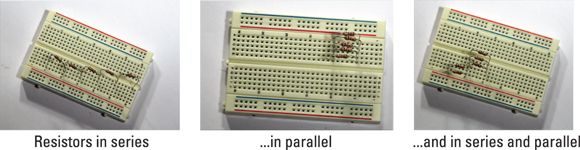
In this project, you assemble five resistors into three different configurations. The first has all five resistors in series. The second has them all in parallel. And the third creates a network of two sets of parallel resistors that are connected in series. Figure 2-6
shows how these three configurations appear when assembled.
FIGURE 2-6:
The assembled resistors for Project 11.
Project 11: Resistors in Series and Parallel
In this project, you experiment with resistors in series and in parallel. You need a multimeter with an ohmmeter function to measure the resistances.
Parts
One solderless breadboard (RadioShack 2760003)
Five
W resistors (brown-black-red)
One multimeter with an ohmmeter function
Steps
Set your multimeter to its ohmmeter function with a range large enough to measure at leastof resistance.
On my ohmmeter, the closest range is
.
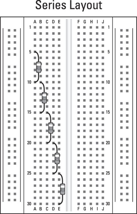
Insert the fiveresistors in series.
Use the following holes on the breadboard:
Resistor
First Lead
Second Lead
1
A5
A10
2
B10
B15
3
C15
C20
4
D20
D25
5
E25
E30
Refer to the Series Layout diagram for the layout of these resistors.
Using your multimeter, measure the resistance of each resistor individually, and then measure the total resistance of two, three, four, and five resistors in series.
To do these measurements, place the meter probes on the leads at the breadboard holes indicated in Table 2-3
. Write your actual measurements in the column on the far right.
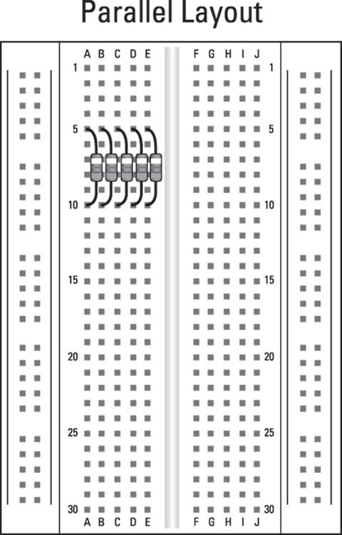
Rearrange the resistors into a parallel circuit.
Remove the resistors and reinsert them into the following holes:
Resistor
First Lead
Second Lead
1
A5
A10
2
B5
B10
3
C5
C10
4
D5
D10
5
E5
E10
Refer to the Parallel Layout diagram for the layout of these resistors.
Use your ohmmeter to measure the resistance of the parallel resistor circuit.
Because there are five
resistors, your measurement should be approximately
.
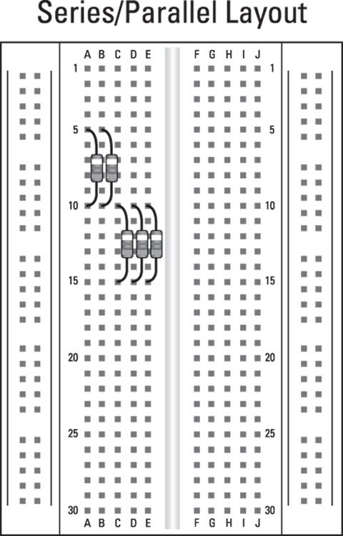
Rearrange the resistors into a series/parallel network.
Remove resistors 3, 4, and 5 and insert them as follows:
Resistor
First Lead
Second Lead
1
A5
A10
2
B5
B10
3
C10
C15
4
D10
D15
5
E10
E15
Refer to the Series/Parallel Layout diagram for the layout of these resistors.
This configuration has the first two resistors in one parallel circuit and the other three in a second parallel circuit. The two parallel circuits are connected to form a series circuit.
Use your ohmmeter to measure the resistance of two parallel circuits and the entire circuit.
You’re done! Unless you’re a glutton for punishment. In that case, feel free to experiment with other combinations of series and parallel resistor circuits. Grab some resistors with other values and throw them into the mix. Each time, do the math to predict what the resulting resistance should be. With some practice, you’ll get good at calculating resistor networks.
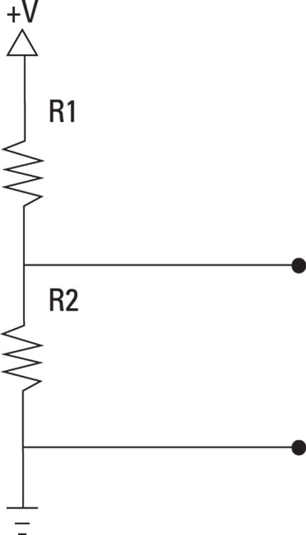
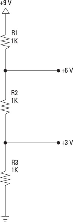
One interesting and useful property of resistors is that if you connect two resistors together in series, you can tap into the voltage at the point between the two resistors to get a voltage that is a fraction of the total voltage across both resistors. This type of circuit is called a voltage divider,
and is a common way to reduce voltage in a circuit. Figure 2-7
shows a typical voltage-divider circuit.
When the two resistors in the voltage divider are of the same value, the voltage is cut in half. For example, suppose your circuit is powered by a 9 V battery, but your circuit really only needs 4.5 V. You could use a pair of resistors of equal value across the battery leads to provide the necessary 4.5 V.
When the resistors are of different values, you must do a little math to calculate the voltage at the center of the divider. The formula is as follows:
For example, suppose you’re using a 9 V battery, but your circuit requires 6 V. In that case, you could create a voltage divider using a
resistor for R1 and a
resistor for R2. Here’s the math:
As you can see, these resistor values cut the voltage down to 6 V.
Dividing Voltage with Resistors
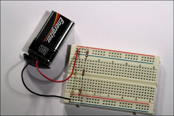
In Project 12, you build a simple voltage divider circuit on a solderless breadboard to provide either 3 V or 6 V from a 9 V battery. The assembled circuit is shown in Figure 2-8
.
FIGURE 2-8:
The assembled voltage divider circuit.
Project 12: A Voltage Divider Circuit
In this project, you build a simple voltage divider circuit using three 1 kΩ resistors, and you use the ohmmeter function of your multimeter to measure the effect of the divider.
Parts
One solderless breadboard (RadioShack 2760003)
One 9 V battery
One 9 V battery snap holder (RadioShack 2700325)
Three
resistor (brown-black-red)
One multimeter with a voltmeter function
Steps
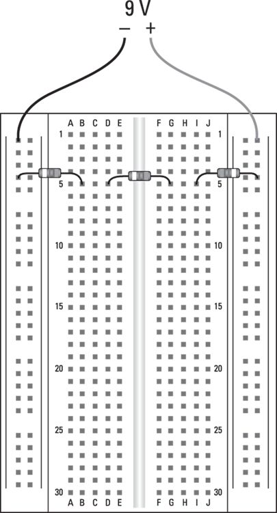
Connect the battery holder.
Insert the black lead into the first hole in the ground bus (on the side nearest column A). Then insert the red lead in the first hole in the positive voltage bus (on the side nearest column J).
Insert the resistors.
Place the resistor leads into the holes indicated in the following table:
Resistor
First Lead
Second Lead
1
Ground bus near row 5
B5
2
D5
G5
3
I5
Positive bus near row 5
Connect the battery.
Use the voltmeter to observe how the voltage is divided.
Set the voltmeter to a range that will measure at least 10 V DC. Then take the measurements indicated in Table 2-5
by touching the meter leads to the resistor leads that are plugged into the holes indicated in the table:
You’re done!
Be sure to unplug the battery from the circuit. If you leave it plugged in, current will continue to flow through the series resistor circuit, and the battery will soon go dead.
Many circuits call for a resistance that can be varied by the user. For example, most audio amplifiers include a volume control that lets the user turn the volume up or down, and you can create a simple light dimmer by varying the resistance in series with a lamp.
A variable resistor is properly called a potentiometer,
or just pot
for short. A potentiometer is simply a resistor with three terminals. Two of the terminals are permanently fixed on each end of the resistor, but the middle terminal is connected to a wiper that slides in contact with the entire surface of the resistor. Thus, the amount of resistance between this center terminal and either of the two side terminals varies as the wiper moves.
Figure 2-9
shows how a typical potentiometer looks from the outside. The resistive track and slider (properly called the wiper
) are enclosed within the metal can, and the three terminals are beneath it. The rod that protrudes from the top of the metal can is connected to the wiper so that when the user turns the rod, the wiper moves across the resistor to vary the resistance.
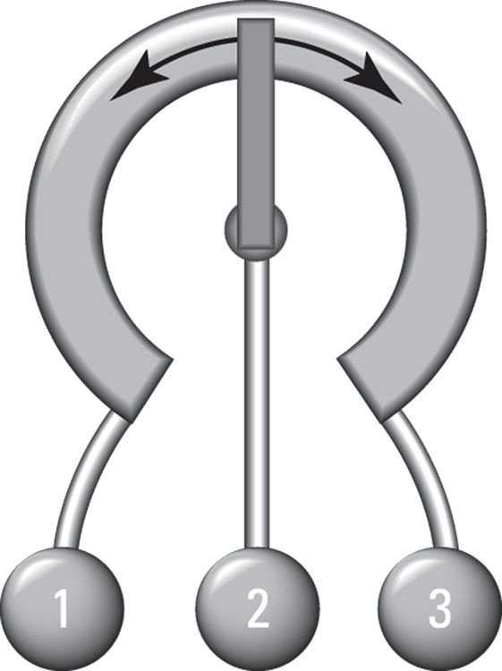
Figure 2-10
shows how a potentiometer works on the inside. Here, you can see that the resistor is made of a semicircular piece of resistive material such as carbon. The two outer terminals are connected to either end of the resistor. The wiper, to which the third terminal is connected, is mounted so that it can rotate
across the resistor. When the wiper moves, the resistance between the center terminal and the other two terminals changes.
The symbol used for a potentiometer in schematic diagrams is shown in the margin. As you can see, the center tap of the resistor is indicated by an arrow that is meant to reflect that the value of the resistance at this terminal varies when the wiper moves.
Potentiometers are rated by their total resistance. The resistance between the center terminal and the two other terminals always adds up to the total resistance rating of the potentiometer. For example, the two resistances split by a
potentiometer always add up to
. When the dial is exactly in the center, both resistances are
. As you move the wiper one way or the other, one resistance increases while the other decreases; but in all cases, the total of the two resistances always adds up to
.
Here are a few other rambling thoughts to keep in mind about potentiometers:
Potentiometers come in a wide variety of shapes and sizes. With a little hunting around in stores or on the Internet, you should be able to find the perfect potentiometer for every need.
Some potentiometers are very small and can be adjusted only by the use of a tiny screwdriver. This type of pot is called a trim pot
, designed to make occasional fine-tuning adjustments to your circuits.
Some potentiometers have switches incorporated into them so that when you turn the knob all the way to one side or pull the knob out, the switch operates to either open or close the circuit.
When the wiper reaches one end of the resistor or the other, the resistance between the center terminal and the terminal on that end is essentially zero. Keep this point in mind when you’re designing circuits. To avoid circuit paths with no resistance, it’s common to put a small resistor in series with a potentiometer.
In some potentiometers, the resistance varies evenly as you turn the dial. For example, if the total resistance is
, the resistance at the halfway mark is
, and the resistance at the one-quarter mark is
. This type of potentiometer is called a linear taper
potentiometer because the resistance change is linear.
Many potentiometers, however, aren’t linear. For example, potentiometers designed for audio applications usually have a logarithmic taper
, which means that the resistance doesn’t vary evenly as you move the dial.
Some variable resistors have only two terminals: one on an end of the resistor itself, the other attached to the wiper. This type of variable resistor is properly called a rheostat
, but most people use the term potentiometer
or pot
to refer to both two- and three-terminal variable resistors.
 Understanding and measuring resistance
 The truth is, all
materials have some resistance. Even the best conductors have a small but measurable amount of resistance. The only exceptions are certain materials called superconductors
that, when chilled to unbelievably low temperatures, conduct with 100 percent efficiency. Unfortunately, you can’t buy superconductors at RadioShack, and even if you could, you can’t buy a freezer at Sears powerful enough to chill the stuff down to absolute zero.
The truth is, all
materials have some resistance. Even the best conductors have a small but measurable amount of resistance. The only exceptions are certain materials called superconductors
that, when chilled to unbelievably low temperatures, conduct with 100 percent efficiency. Unfortunately, you can’t buy superconductors at RadioShack, and even if you could, you can’t buy a freezer at Sears powerful enough to chill the stuff down to absolute zero. ). The standard definition of one ohm
is simple: It’s the amount of resistance required to allow one ampere of current to flow when one volt of potential is
applied to the circuit. In other words, if you connect a one-ohm resistor across the terminals of a one-volt battery, one amp of current will flow through the resistor.
). The standard definition of one ohm
is simple: It’s the amount of resistance required to allow one ampere of current to flow when one volt of potential is
applied to the circuit. In other words, if you connect a one-ohm resistor across the terminals of a one-volt battery, one amp of current will flow through the resistor. ) is actually a very small amount of resistance. Resistances in the hundreds, thousands, or even millions of ohms are usually called for in electronic circuits.
 , and a 1,000,000-ohm resistance is written as
  .
. ). In reality, however, only superconductors have a resistance of
  . Even copper wire has some resistance. Because of that, the resistance of wire is usually measured in terms of ohms per kilometer or per mile. Electronic circuits usually deal with wires that are at most a few inches or feet long, not kilometers or miles.
 , and the current flowing through the lamp is 250 mA, which is the same as 0.25 A. Then, you can calculate the voltage as follows:


 of resistance connected to two AA batteries for a total voltage of 3 V. Then you can calculate that the current flowing through the lamp is 0.25 A (or 250 mA), as follows:
 , like this:
 The most important thing to remember about Ohm’s law is that you must always do the calculations in terms of volts, amperes, and ohms. For example, if you measure the current in milliamps (which you usually will in electronic circuits), you must convert the milliamps to amperes by dividing by 1,000. For example, 250 mA is 0.25 A.
 inch long, and the leads are about an inch long, making the entire thing about
  inches long.
 In schematic diagrams, a resistor is represented by a jagged line, like the one shown in the margin. The resistance value is typically written next to the resistor symbol. In addition, an identifier such as R1 or R2 is also sometimes written next to the symbol.
 In some schematics, particularly those drawn in Europe, the symbol shown in the margin is used instead of the jagged line.
 Many electronic components have an appetite for current that must be regulated by resistors. One of the best known are light-emitting diodes (LEDs), which are a special type of diode that emits visible light when current runs through it. Unfortunately, LEDs don’t know when to step away from the table when it comes to consuming current. That’s because they have very little internal resistance. Unfortunately, LEDs don’t have much tolerance for current, so too much current will burn them out. As a result, it’s always prudent — essential, in fact — to place a resistor in series with an LED to keep the LED from burning itself up. (You can learn more about LEDs in
  .
.


 resistor with a
  percent tolerance actually has a value somewhere between 5 percent above and 5 percent below
  , which works out to somewhere between
  and
and  . A
. A  resistor with a 10 percent tolerance has an actual value somewhere between
  and
and  .
. percent or
  percent tolerance resistors are fine for most work, including all the circuits presented in this book (unless otherwise indicated).


 W or
W or  W. You can also find resistors rated for
  W or 1 W, but they’re rarely needed in the types of electronic projects you build in this book. Unless otherwise stated, all the resistors used in this book are rated at
  W.
W. resistor will have 3 V across it, you can calculate that 30 mA of current will flow through the resistor by dividing the voltage by the resistance (
 , which is 30 mA).
 W (0.25 W) resistor. (A
  W resistor should be able to handle this amount of power too, but it’s always better to err on the large side when it comes to power ratings.)
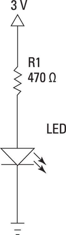
 resistor? Why not a larger or a smaller value? In other words, how do you determine what size resistor to use in a circuit like this?
 .
. Do not
connect the LED directly to the battery without a resistor. If you do, the LED will flash brightly, and then it will be dead forever.
Do not
connect the LED directly to the battery without a resistor. If you do, the LED will flash brightly, and then it will be dead forever.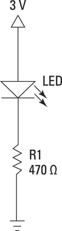
 resistor in a critical spot. You run down to your local RadioShack and are miffed because you can’t find any
  resistors. So you go online and search your favorite online suppliers and are even more miffed to discover that they don’t have
  resistors either. You can buy
  resistors and
  resistors, but no one seems to have any
  resistors.
 resistor and hope it will be close enough?
 resistor, you can combine a
  resistor and a 100 Ω resistor in series. Adding these two resistances together gives you a total resistance of
  .
. of resistance, you could use a
  resistor and eight
  resistors in series.
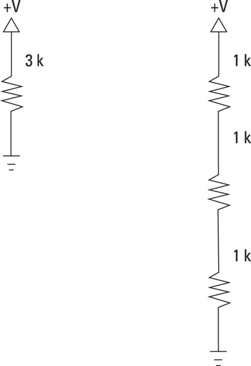
 resistors in parallel is
  and the total resistance of four,
  resistors is
  .
.
 and a
and a  resistor in parallel:
 ,
,  , and
, and  :
:
 . That’s more precision than you could possibly want, so you can probably safely round it off to
  , or maybe even
  .
. resistors and one
  resistor. These resistors are arranged in a mixture of serial and parallel connections.
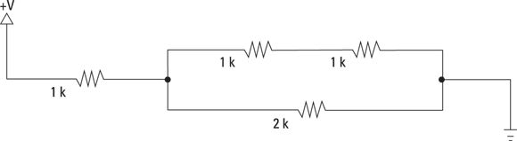
 resistors that are in series with a single
  resistor. Now, you have two,
  resistors in parallel. Remembering that the total resistance of two resistors with the same value is half the resistance value, you can replace these two,
  resistors with a single
  resistor. You’re now left with two,
  resistors in series. Thus, the total resistance of this circuit is
  .
.
 W resistors (brown-black-red)
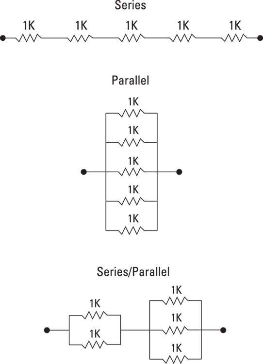
 of resistance.
 .
. resistors in series.
 resistors, your measurement should be approximately
  .
.


 resistor for R1 and a
  resistor for R2. Here’s the math:
 resistor (brown-black-red)
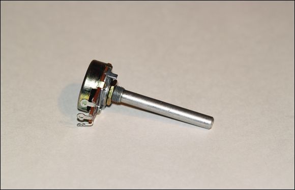
 The symbol used for a potentiometer in schematic diagrams is shown in the margin. As you can see, the center tap of the resistor is indicated by an arrow that is meant to reflect that the value of the resistance at this terminal varies when the wiper moves.
 potentiometer always add up to
  . When the dial is exactly in the center, both resistances are
  . As you move the wiper one way or the other, one resistance increases while the other decreases; but in all cases, the total of the two resistances always adds up to
  .
. , the resistance at the halfway mark is
  , and the resistance at the one-quarter mark is
  . This type of potentiometer is called a linear taper
potentiometer because the resistance change is linear.
. This type of potentiometer is called a linear taper
potentiometer because the resistance change is linear.