A little bit of knowledge can sometimes be a problem. For instance, if you think that with only a joist and rafter span table you can do your own structural design, you are mistaken. Though you could get by in most conventional stud-framed houses, timber-framed dwellings are less forgiving. There are no tables for members that are notched or mortised. There are no tables for joints. One reason I wrote this book is that there are few timber-framed house plans (and no other books) available for the builder without an engineering background. In the hall-and-parlor house design outlined in this book, the timbers and their joints have already been sized to meet the loads shown in the table on this page.
With the exception of the roof load, these numbers are consistent with most building codes, though you should check with your local code official. Roof loads are more variable and depend on the amount of snow or wind in your area. Again, check with your local official. The timber sizes included here are designed to meet or exceed these loadings using eastern white pine for all but the main posts and braces. Though it is one of the weakest of commercially available species, it is inexpensive and readily available in the Northeast. If you follow the framing plans, use the grades of timber specified, cut reasonably close tolerances on the joints, sheath the structure properly, and use the building as a residence (and not an anvil warehouse), your frame should stand indefinitely, barring any natural disasters.
Ground Floor: |
40 psf (pounds per square foot) live load |
Second floor: |
30 psf live load |
Attic floor: |
30 psf live load |
Roof: |
40 psf live load |
If, on the other hand, you wish to modify the design, have larger loading requirements, or just want to understand structural design, you can follow along through the design of a couple of members. These examples should not, however, be considered a substitute for a complete engineering-level structural understanding.
The first-floor joists in our design are spaced every 2 feet 6 inches on center. Changing this spacing affects the loading on each joist. Those joists in the end bays span greater distances than those in the central bay. I have designed the joists for the larger span of the two bay types and recommended the same joist size and joinery for both spans. The span for members is usually taken as the center-to-center distance of the members supporting them. Thus, the span for the 14-foot bay is 13 feet 2 inches. The loading on a joist is the sum of the live load (from the code) and the dead load (the weight of the flooring system). On this house, a typical dead load might look like the following:
¾-inch hardwood (maple) finish floor |
2.75 psf |
¾-inch spruce subfloor |
1.66 psf |
pine floor joist |
3.10 psf |
(estimated size 6×7, with 7.76 pounds per foot of length for each 2.5 square feet of floor it supports) |
|
Total dead load |
7.51 psf |
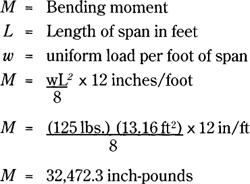
I erred on the side of safety and assumed an even 10 psf dead load. Added to the live load of 40 psf, the floor load totals 50 psf. Since each joist supports 2.5 square feet of floor for every foot of its length, its loading is 125 pounds per foot of length. Next, I will demonstrate how to investigate the joist for bending, deflection, and horizontal shear. As each of these could cause problems — if not collapse — the joist must be checked for all three forms of stress.
Bending. A joist will break when the stresses in the wood exceed the allowable bending stresses. Breaks usually occur in the middle of the joist. During extreme loading, the fibers in the upper half of the joist are compressed beyond their capacity and those in the lower half are stretched (placed in tension) beyond their capacity. The fibers in the middle or neutral axis are under little or no stress; the greatest stresses occur on the top and bottom surfaces. Structural steel I-beams are shaped with more material where the greatest bending stresses occur. In technical terms, a floor joist is simply supported, which means it spans between two supports. Calculating the stresses of a joist is relatively easy:
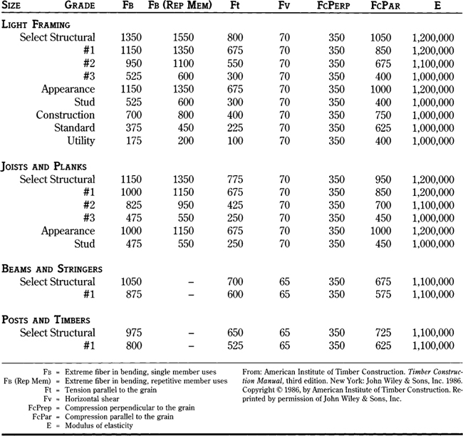
To determine our joist size from this bending moment, plug in the bending strength value for the chosen species of wood. What value do we use? The allowable unit stresses vary with the cross-sectional size of the member. The larger the member, the lower the unit stress, which is because larger members tend to have larger checks and more hidden defects. Structural dimension lumber is divided into four categories by size (see the table above).
Light framing |
2-4 inches thick, 2-4 inches wide |
Structural joists and planks |
2-4 inches thick, 5 inches or wider |
Beams and stringers |
5 inches or thicker, width more than 2 inches greater than thickness |
Posts and timbers |
5×5 or larger, width less than or equal to 2 inches more than thickness |
Each size classification has its various grades (see chart of design values for eastern white pine on page 178).
Our joist will probably fall into the joists and planks category. With #1 grade, use Fb = 1000, which goes into the formula:
S = M/Fb S = 32,472.3/1000 = 32.47
M = bending moment |
Fb = extreme fiber in bending from table |
S = section modulus |
This section modulus is a number that represents the size and cross section of a beam. If we know S, we can select timber sizes. The S required to meet the bending moment is 32.47. How large a timber is needed to meet this? To determine S for a given beam:
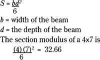
Since this amount is slightly greater than required, this size passes the bending test.
Deflection. Now, I will check the 4×7 to see if it meets the deflection criteria. The formula for a simply supported and uniformly loaded beam is:
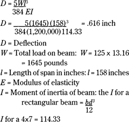
The maximum allowable deflection is set by the building code. Though sagging floors may not be a structural problem, they can cause cracking plaster, sloping floors, and make china cabinets rattle when you walk by, as well as create a feeling of uneasiness. Thus, deflection is typically limited to 1/360th of the span when considering just the live load, or 1/240th of the span when considering both the live and dead loads. Since the loading in this case includes both live and dead loads already, I will use 1/240. Thus, the allowable deflection is 158/240 or .658 inch. Since .624 inch is less than the limit, the beam is fine.
Shear. There are two types of shear: vertical and horizontal. Vertical shear is mostly a concern in masonry work — because of the fiber structure of wood, vertical shear is not a concern for timber-framed buildings. Horizontal shear must be considered, however. A floor joist can meet the above bending and deflection requirements but still fail in horizontal shear. But what is horizontal shear?
DESIGN VALUES FOR EASTERN WHITE PINE
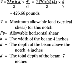
Consider a beam made up of two stacked boards. When weight is applied, the boards sag and slide against each other. They slide the most at their ends and not at all in the middle of the span. Horizontal shearing, then, is this sliding action in a single beam and it, too, is greatest at the beam’s ends and null in the middle of the span. Shear is a problem in timber-framed buildings when members are notched or otherwise reduced in cross section at joints. The ends of our first-floor joists must be reduced in depth where they enter the sills. Otherwise, the sills would have to be 3 or 4 inches deeper in section than the floor joist to provide wood below the joint. Since 10- or 11-inch deep sills are not practical, the joist is notched down in depth at the ends to work with an 8-inch deep sill. When a joist fails in horizontal shear at its notched end, a crack develops at the notch, though we don’t actually see the two halves sliding against each other. Once the halves slide a fraction of an inch, the cohesion between the fibers is broken. The joist acts like two beams, with an unsupported lower beam and an upper beam that is not strong enough to support the load. A joist notched with a square-cornered notch tends to concentrate these shearing stresses at the corners of the notch. It is common to see failures of joists notched in this way in old structures. The best way to handle the stress is to angle the cut back at approximately 45 degrees to spread out the stresses. By removing additional wood, the joist is strengthened. It is common to see in old structures that joists cut in this way have not failed. In fact, such joists would usually break in the center of the span from bending rather than fail at the notch in shear. I know of a house with approximately 8-inch diameter log joists, just flattened on the top, that were notched down to only 1½ inches deep and 6 inches wide at their ends. After 250 years, these joists have not failed.

The floor joists are reduced in depth where they enter the sill to keep the sill size manageable. Avoid stress concentration there by angling the joist back from the notch.
Notching a joist at the ends does not affect either bending or deflection, just the allowable shear. I must check the shear by first determining the load on the joist end. In a uniformly loaded beam such as a floor joist, the weight on each end is half the total load on the beam, or one-half of 1645, or 822.5 pounds. There are two formulas, one for square-cornered notches and the other for tapered- or angled-corner notches. I will solve for each type.
A joist with a square-cornered notch is not sufficient in this case to support the loads.
Angled-corner notch
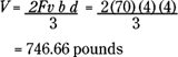
In this case, d is the depth of the beam at the notch. Although this angled notch is considerably stronger, it still isn’t sufficient. Since we don’t want to cut notches any deeper into the sills and girders or make the sills and girders deeper, the joists need to be wider. If we try a 5×7 joist, a funny thing happens. Because the joist is 5 inches thick, it falls into the size category of posts and timbers. Using the same grade (#1), the allowable horizontal shear is now 65. The V for a 5×7 reduced to a 5×4 at the end is 866.66 pounds. Since that is greater than 826, it passes the shear test. But, since the new size changed the dimensions to the posts and timbers category, the other allowable stresses have also been reduced. The allowable bending stress (Fb) is now only 800. After determining the required section modulus again, it becomes apparent that a 5×7 is not quite strong enough.
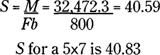
It just squeaks by, but it is too close for comfort. If a joist were slightly undersized, there could be a problem. I prefer to use the next larger size.
S for a 6×7 is 49, which is more than sufficient to meet bending requirements. For deflection, E in the new category is also less: 1,100,000 instead of 1,200,000. But a 6×7 has a higher I value that more than makes up for the reduction in the modulus of elasticity. From the deflection formula, the actual deflection for a 6×7 is .448 inches, which is well under the maximum allowable deflection of .624 inches. The foregoing calculations show that horizontal shear is an important sizing factor for timbers reduced at their ends. It is also clear that wider, more squarish beams perform better for horizontal shear. For bending and deflection, narrower but deeper beams perform better. What we need, then, is a beam that is the best compromise between the two. Traditionally, beam cross sections varied depending on their method of conversion from the log and the use of the building. Although I discuss conversion elsewhere, I can tell you that squarish beams are easier to hew from round logs. Narrow stock like 2×8s are easy to saw out. In old barns, the floor joists are often logs hewn on the top and sometimes the bottom as well. They are wider than deep, and although these floors may sag considerably under heavy loads, they will not fail in horizontal shear or bending. Deflection was not a concern for the farmer, but ultimate strength was. In fact, the sagging was a sort of visual gauge of the floor’s capacity. A stiff floor of 2×12s that is overloaded will not sag appreciably but it will fail abruptly; such a floor lacks visual clues as to its strength.
As plastered ceilings became popular in the latter parts of the eighteenth century, joists became narrower but deeper to increase the stiffness of the ceiling, which was necessary to keep the plaster from cracking. Thus, 2×8s and 2×10s became common in houses. These joists were usually notched where they entered the carrying timber (typically of the same depth as the joists) with the square-cornered variety to gain nailing for lath. They were often notched to half their depth and joists split at the notch from shear are common.
In this design, the second-floor joists need not be as heavy. The second-floor loading is less than the first’s and the entire joist end can be housed into the girding beam. The girding beam is not under the same constraints as the sills and can be deeper in cross section as necessary. Although there is more work involved, fully housed joists are stronger in horizontal shear and provide a bit more finished appearance for the living space. The girding beams support the second-floor joists and are a key structural element. I will next examine how to go about sizing such a beam.
Though there are four of these members in the second floor, I only designed for the one with the greatest loading and then made all four the same. The end wall girding beams are supported by the vertical wall planks and support only half a floor bay. I will look at one of the two center girding beams.
These beams carry half of the floor on either side, an 11-foot wide floor. In the two interior crossframes, a one-story (prick) post supports each girding beam. The brace at the other end picks up some vertical weight, though not all of it, and the span can be adjusted to reflect this. I will use 10.5 feet as the span. A beam continuous over three or more supports is stronger than a simply supported one, but since joinery reduces the cross section over the posts, think of each span as separate beams. This errs on the side of safety. The beam receives its loads only at the joist locations, and each joist carries a floor section 2.5 feet wide.
Live load: |
30 psf |
Dead load: |
10 psf |
Total load: |
40 psf |
At each of the loading points, the load is 2.5 feet × 11 feet × 40 psf = 1100 pounds. The load of the beam must also be added to this number. Assuming an 8×10 beam of eastern white pine and about 14 pounds per linear foot, the beam has about 35 pounds added to each loading point. To determine the bending stress, I use a different formula (from Parker and Ambrose [1984], p. 72) because the beam is loaded at three points rather than uniformly.

To determine the required section modulus, divide M (35,752.5) by the allowable bending stress for pine, which is 800 (#1, post and timbers). Thus, the required section modulus is 44.7. If the floor joists just sat on top of the girding beam without notching, a 6×8 timber would probably suffice. However, when a beam is notched or mortised to accept other members, the beam is weakened where wood is removed. How much wood and where exactly you remove it determines the final strength. It is important to determine the actual section modulus at the joist notches where the beam is weakest. The section modulus of the beam at these notches is not just the cross sectional area of the beam remaining after the notching; it is very important where the wood is removed. If wood is removed on the top or bottom surfaces, the beam is weakened substantially. If it is removed from the middle near the neutral axis, it is hardly weakened at all, which is apparent from various illustrated cross sections and their resultant percentage of full strength.
COMPARATIVE CROSS SECTIONS THROUGH GIRDING BEAM AT JOIST LOCATIONS

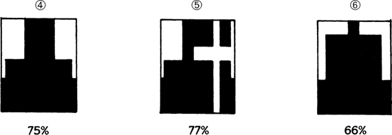
Example 1 shows a full 8×10 beam without any cuts. Example 2 shows a beam with mortises cut for soffit tenons with diminished haunches. Because the wood on the top and bottom surfaces is virtually uncut, it is approximately 95 percent of full strength. It would seem that structurally this is the ideal joint for floor joists. The only drawback is that the cutting and assembly of the frame becomes a bit more time consuming. Example 3 is the same joint but with ⅞-inch peg holes for each mortise. S is now 72 percent of full strength, a significant change. There is an argument, though, that the wood removed by the peg hole from the upper half (compression half) is replaced by a tight-fitting peg. Example 4 has simple drop-in joist pockets and is approximately 75 percent of full strength. Example 5 is the actual section in this design in the middle of the span. It has a drop-in joist on one side and a tying joist with a peg hole on the other side. It is 77 percent of full strength. The final example has a drop-in lap dovetail on either side. Because most of the top surface is notched, it has the lowest strength, though there is more wood left than examples 3,4, and 5; it is about 66 percent of full strength. I decided on an 8×10 notched as in example 5, giving us a section modulus of about 103, far more than the 45 required. An 8×10 is used because there should be some depth below the joist pockets and wood left between them on the top side. Using a smaller timber is not practical. Here is an example of sizing a member mostly to accommodate the joinery.
How does one figure the actual section modulus of a beam or post where it is notched? The process is a bit too involved to be included herein, but to find out more see pages 30 to 31 of Simplified Design of Structural Wood (Parker 1979).
Bearing. A beam can meet all the above criteria but still lack sufficient bearing area where it sits on its supports and crushing of the fibers can result. In other words, design joints with sufficient weight-bearing area on both members. First, determine the load on the joint. Then, divide the load by the allowable compression value for the particular species and grade. Use Fc (compression parallel to grain) for loads bearing on end grain such as a post shoulder. Use Fc Perp (compression perpendicular to grain) for loads bearing on side grains such as joist pockets.
There are, of course, many other timbers to size in this design as well as other loads, such as wind and earthquake loads. The above examples are provided only to demonstrate the complexity of design of a timber-framed structure. A thorough study of all the loads on the timbers and joints is beyond the scope of this book. Structural engineers are best suited to analyze timber-framed structures.