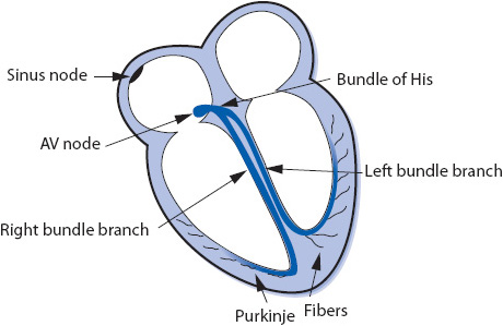
Figure 3-1. The conduction system of the heart.
KNOWLEDGE COMPETENCIES
1. Correctly identify key elements of electrocardiogram (ECG) waveforms, complexes, and intervals:
• P wave
• QRS complex
• T wave
• ST segment
• PR interval
• QT interval
• RR interval
• Rate (atrial and ventricular)
2. Compare and contrast the etiology, ECG characteristics, and management of common cardiac rhythms and conduction abnormalities:
• Sinus node rhythms
• Atrial rhythms
• Junctional rhythms
• Ventricular rhythms
• AV blocks
3. Describe the indications for, and use of, temporary pacemakers, defibrillation, and cardioversion for the treatment of serious cardiac arrhythmias.
Continuous monitoring of cardiac rhythm in the critically or acutely ill patient is an important aspect of cardiovascular assessment. Frequent analysis of electrocardiogram (ECG) rate and rhythm provides for early identification and treatment of alternations in cardiac rhythm, as well as abnormal conditions in other body systems. This chapter presents a review of basic cardiac electrophysiology and information essential to the identification and treatment of common cardiac arrhythmias. Advanced cardiac arrhythmias, and 12-lead ECG interpretation, are described in Chapter 18, Advanced ECG Concepts.
The electrical impulse of the heart is the stimulus for cardiac contraction. The cardiac conduction system is responsible for the initiation of the electrical impulse and its sequential spread through the atria, atrioventricular (AV) junction, and ventricles. The conduction system of the heart consists of the following structures (Figure 3-1):

Figure 3-1. The conduction system of the heart.
Sinus node: The sinus node is a small group of cells in the upper right atrium that functions as the normal pacemaker of the heart because it has the highest rate of automaticity of all potential pacemaker sites. The sinus node normally depolarizes at a regular rate of 60 to 100 times/min.
Atrioventricular (AV) node: The AV node is a small group of cells in the low right atrium near the tricuspid valve. The AV node has three main functions:
1. Its major job is to slow conduction of the impulse from the atria to the ventricles to allow time for the atria to contract and empty their blood into the ventricles.
2. Its rate of automaticity is 40 to 60 beats/min and can function as a backup pacemaker if the sinus node fails.
3. It screens out rapid atrial impulses to protect the ventricles from dangerously fast rates when the atrial rate is very rapid.
Bundle of His: The bundle of His is a short bundle of fibers at the bottom of the AV node leading to the bundle branches. Conduction velocity accelerates in the bundle of His and the impulse is transmitted to both bundle branches.
Bundle branches: The bundle branches are bundles of fibers that rapidly conduct the impulse into the right and left ventricles. The right bundle branch travels along the right side of the interventricular septum and carries the impulse into the right ventricle. The left bundle branch has two main divisions: the anterior fascicle and the posterior fascicle, which carry the impulse into the left ventricle.
Purkinje fibers: The Purkinje fibers are hairlike fibers that spread out from the bundle branches along the endocardial surface of both ventricles and rapidly conduct the impulse to the ventricular muscle cells. Cells in the Purkinje system have automaticity at a rate of 20 to 40 beats/min and can function as a backup pacemaker if all other pacemakers fail.
The electrical impulse normally begins in the sinus node and spreads through both atria in an inferior and leftward direction, resulting in depolarization of the atrial muscle. When the impulse reaches the AV node, its conduction velocity is slowed before it continues into the ventricles. When the impulse emerges from the AV node, it travels rapidly through the bundle of His and down the right and left bundle branches into the Purkinje network of both ventricles, and results in depolarization of the ventricular muscle. The spread of this wave of depolarization through the heart produces the classic surface ECG, which can be recorded by an electrocardiograph (ECG machine) or monitored continuously on a bedside cardiac monitor.
The ECG waveforms, complexes, and intervals are illustrated in Figure 3-2.
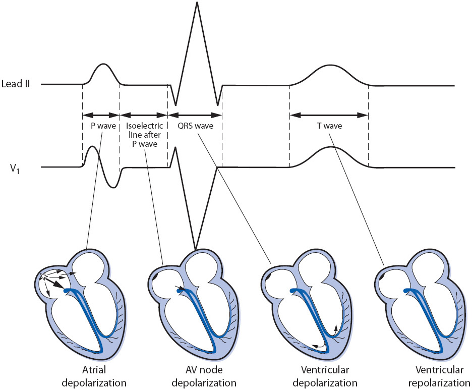
Figure 3-2. Electrocardiographic waves, complexes, and intervals in leads II and V1.
The P wave represents atrial muscle depolarization. It is normally 2.5 mm or less in height and 0.11 second or less in duration. P waves can be upright, inverted, or biphasic depending on how the electrical impulse conducts through the atria and on which lead it is being recorded.
The QRS complex represents ventricular muscle depolarization. A Q wave is an initial negative deflection from baseline. An R wave is the first positive deflection from baseline. An S wave is a negative deflection that follows an R wave. The shape of the QRS complex depends on the lead being recorded and the ventricular activation sequence; not all leads record all waves of the QRS complex. Regardless of the shape of the complex, ventricular depolarization waves are called QRS complexes (Figure 3-3). The width of the QRS complex represents intraventricular conduction time and is measured from the point at which it first leaves the baseline to the point at which the last wave ends. Normal QRS width is 0.04 to 0.10 second in an adult. When describing the shape of the QRS complex in writing, a capital letter is used when the voltage of a wave is 5 mm or more, and a lower case letter is used for smaller waves, as in Figure 3-3.
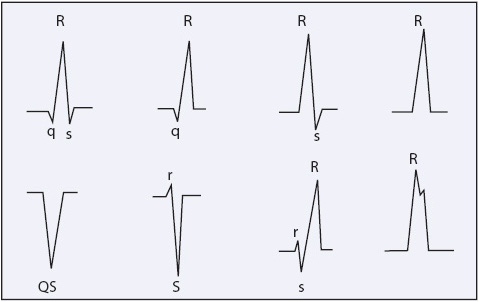
Figure 3-3. Examples of different configurations of QRS complexes. (Jacobson C, Marzlin K, Webner C. Cardiovascular Nursing Practice: A Comprehensive Resource Manual and Study Guide for Clinical Nurses. Burien, WA: Cardiovascular Nursing Education Associates; 2007.)
The T wave represents ventricular muscle repolarization. It follows the QRS complex and is normally in the same direction as the QRS complex. T waves can be upright, flat, or inverted depending on many things, including the presence of myocardial ischemia, electrolyte levels, drug effect, myocardial disease, and the lead being recorded.
The U wave is a small, rounded wave that sometimes follows the T wave and is thought to be due to repolarization of the M-cells (mid-myocardial cells) in the ventricles. U waves should be positive, especially when the T wave is positive. Large U waves can be seen when repolarization is abnormally prolonged, with hypokalemia, or with certain drugs.
The PR interval is measured from the beginning of the P wave to the beginning of the QRS complex and represents the time required for the impulse to travel through the atria, AV junction, and to the Purkinje system. The normal PR interval in adults is 0.12 to 0.20 second. The PR segment extends from the end of the P wave to the beginning of the QRS complex.
The ST segment represents early ventricular repolarization. It begins at the end of the QRS complex (J point) and extends to the beginning of the T wave. The J point is where the QRS complex ends and the ST segment begins. The ST segment should be at the isoelectric line.
The QT interval measures the duration of ventricular depolarization and repolarization and varies with age, gender, and heart rate. The QT interval is measured from the beginning of the QRS complex to the end of the T wave. Because heart rate greatly affects the length of the QT interval, the QT interval must be corrected to a heart rate of 60 beats/min (QTc). This correction is usually done using the Bazett formula:
QTc = measured QT interval divided by the square root of the RR interval (all measurements in seconds)
The QTc should not exceed 0.45 second in men and 0.46 second in women.
The ECG is a graphic record of the electrical activity of the heart. The spread of the electrical impulse through the heart produces weak electrical currents that can be detected and amplified by the ECG machine and recorded on calibrated graph paper. These amplified signals form the ECG tracing, consisting of the waveforms and intervals described previously, that are inscribed onto grid paper. The grid on the paper consists of a series of small and large boxes, both horizontal and vertical; horizontal boxes measure time, and vertical boxes measure voltage (Figure 3-4). On the horizontal axis, each small box is equal to 0.04 second, and each large box is equal to 0.20 second. On the vertical axis, each small box measures 1 mm and is equal to 0.1 mV; each large box measures 5 mm and is equal to 0.5 mV. In addition to the grid, most ECG papers place a vertical line in the top margin at 3-second intervals or place a mark at 1-second intervals.
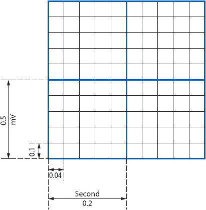
Figure 3-4. Time and voltage lines on ECG paper at standard paper speed of 25 mm/s. Horizontal axis measures time: each small box = 0.04 second, one large box = 0.20 second. Vertical axis measures voltage and also represents mm of ST segment deviation: each small box = 0.1 mV or 1 mm, one large box = 0.5 mV or 5 mm. (Gilmore SB, Woods SL. Electrocardiography and vectorcardiography. In: Woods SL, Froelicher ES, Motzer SU, eds. Cardiac Nursing. 3rd ed. Philadelphia, PA: JB Lippincott; 1995:291.)
Cardiac monitoring provides continuous observation of the patient’s heart rate and rhythm and is a routine nursing procedure in all types of critical care and telemetry units as well as in emergency departments, postanesthesia recovery units, and many operating rooms. Cardiac monitoring has also become common in areas where patients receive treatments or procedures requiring conscious sedation or where the administration of certain medications could result in cardiac arrhythmias. The goals of cardiac monitoring can range from simple heart rate and basic rhythm monitoring to sophisticated arrhythmia diagnosis and ST-segment monitoring for cardiac ischemia detection. Cardiac monitoring can be done using a 3-wire, 5-wire, or 10-wire cable, which connects the patient to the cardiac monitor or portable telemetry box.
The choice of monitoring lead is based on the goals of monitoring in a particular patient population and by the patient’s clinical situation. Because arrhythmias are the most common complication of ischemic heart disease and myocardial infarction (MI), monitoring for arrhythmia diagnosis is a priority in these patients. Although many arrhythmias can be recognized in any lead, research consistently shows that leads V1 and V6, or their bipolar equivalents MCL1 and MCL6, are the best leads for differentiating wide QRS rhythms (Table 3-1). The QRS morphologies displayed in these leads are useful in differentiating ventricular tachycardia (VT) from supraventricular tachycardia with aberrant intraventricular conduction and for recognizing right and left bundle branch block (see Chapter 18, Advanced ECG Concepts).
TABLE 3-1. EVIDENCE-BASED PRACTICE: BEDSIDE CARDIAC MONITORING FOR ARRHYTHMIA DETECTION
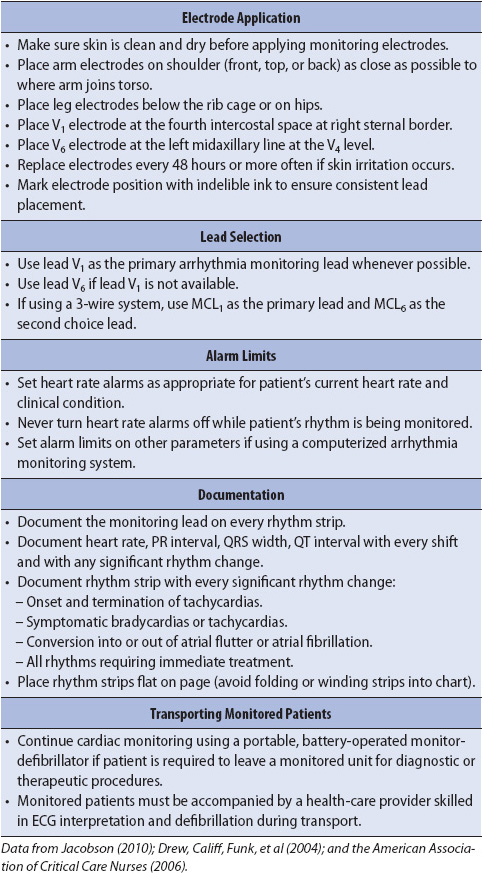
Correct placement of monitoring electrodes is critical to obtaining accurate information from any monitoring lead. Most currently available bedside monitors utilize either a 3-wire or a 5-wire monitoring cable. A 5-wire system offers several advantages over the 3-wire system (Table 3-2). With a 5-wire system, it is possible to monitor more than one lead at a time and it is possible to monitor a true unipolar V1 lead, which is superior to its bipolar equivalent MCL1 in differentiating wide QRS rhythms. With a 5-wire system, all 12 standard ECG leads can be obtained by selecting the desired lead on the bedside monitor and moving the one chest lead to the appropriate spot on the thorax to record the precordial leads V1 through V6 (see Chapter 18, Advanced ECG Concepts). Figure 3-5 illustrates correct lead placement for a 5-wire system. Arm electrodes are placed on the shoulders as close as possible to where the arms join the torso. Placing the arm electrodes on the posterior shoulder keeps the anterior chest area clear for defibrillation paddles if needed, and avoids irritating the skin in the subclavicular area where an intravenous (IV) catheter might need to be placed. Leg electrodes are placed at the level of the lowest ribs on the thorax or on the hips. The desired V or precordial lead is obtained by placing the chest electrode at the appropriate location on the chest and selecting “V” on the bedside monitor. To monitor in V1, place the chest electrode in the fourth intercostal space at the right sternal border. To monitor in V6, place the chest electrode at the left midaxillary line at the V4 level (V4 level is fifth intercostal space, midclavicular line).
TABLE 3-2. ADVANTAGES OF COMMON MONITORING LEADS
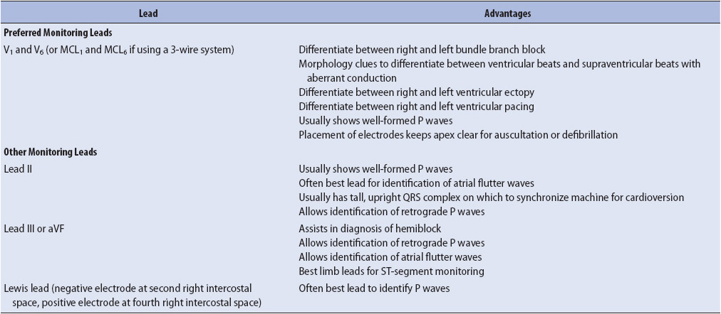
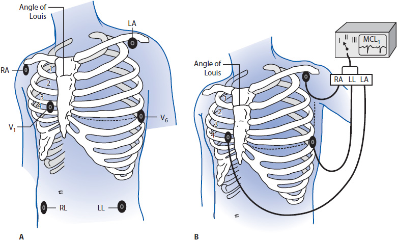
Figure 3-5. (A) Correct electrode placement for using a 5-wire monitoring cable. Right and left arm electrodes are placed on the shoulders and right and left leg electrodes are placed low on the thorax or on the hips. With the arm and leg electrodes placed as illustrated, leads I, II, III, aVR, aVL, and aVF can be obtained by selecting the desired lead on the bedside monitor. To obtain lead V1 place the chest lead in the fourth intercostal space at the right sternal border and select “V” on the bedside monitor. To obtain lead V6, place the chest lead at the level of V4 in the left midaxillary line and select “V” on the bedside monitor. (B) Correct lead placement for obtaining MCL1 and MCL6 using a 3-wire lead system. Place the right arm electrode on the left shoulder; the left arm electrode in the fourth intercostal space at the right sternal border; and the left leg electrode at the level of V4 in the left midaxillary line. To monitor in MCL1, select lead I on the bedside monitor. To monitor in MCL6, select lead II on the bedside monitor. (Adapted from Drew BJ. Bedside electrocardiogram monitoring. AACN Clin Issues Crit Care Nurs. 1993;4:26, 28.)
When using a 3-wire monitoring system with electrodes placed in their conventional locations on the right and left shoulders and on the left hip or low thorax, leads I, II, or III can be monitored by selecting the desired lead on the bedside monitor. It is not possible to obtain a true unipolar V1 or V6 lead with a 3-wire system. In this case, the bipolar equivalents MCL1 and MCL6 can be used as substitutes for V1 and V6 but to obtain them requires placing electrodes in unconventional places. Figure 3-5 shows electrode placement for a 3-wire system that allows the user to monitor either MCL1 or MCL6. Place the right arm electrode on the left shoulder, the left arm electrode at the V1 position (fourth intercostal space at the right sternal border), and the left leg electrode in the V6 position (fifth intercostal space at the left midaxillary line). With electrodes in this position, select “lead I” on the monitor to obtain MCL1 and switch to lead II on the monitor to record MCL6.
The electrode sites on the skin should be clean, dry, and relatively flat. Shave hair, if present, and clean the skin with alcohol to remove any oils. Mildly abrade the skin with a gauze or abrading pad supplied on electrode packaging to improve transmission of the ECG signal. Apply the pregelled electrodes to the chest in the appropriate locations. Set the heart rate alarm limits based on the patient’s clinical situation and current heart rate. Bedside monitoring systems have default alarms that adjust the high- and low-rate limits based on the learned heart rate. Electrodes are changed often enough to prevent skin breakdown and provide artifact-free tracings.
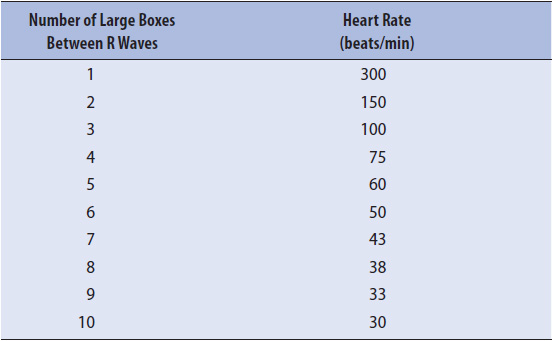
Heart rate can be obtained from the ECG strip by several methods. The first, and most accurate if the rhythm is regular, is to count the number of small boxes (one small box = 0.04 second) between two R waves, and then divide that number into 1500. There are 1500 boxes of 0.04-second interval in a 1-minute strip (Figure 3-6A). Another method is to count the number of large boxes (one large box = 0.20 second) between two R waves, and then divide that number into 300 or use a standardized table (Table 3-3).
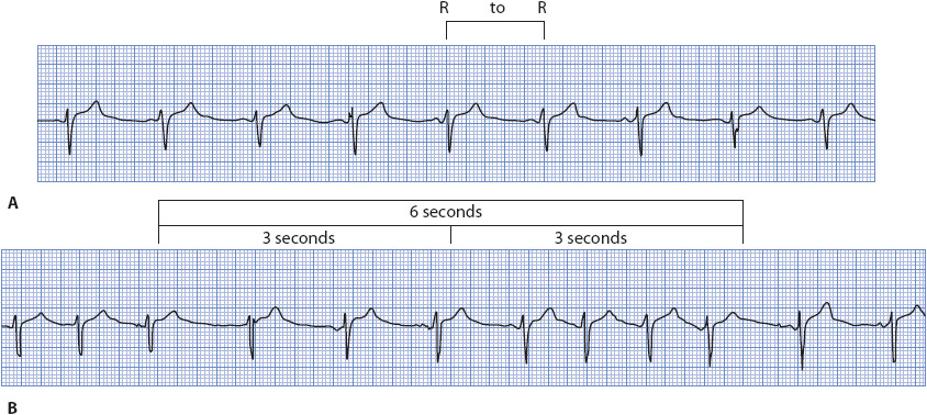
Figure 3-6. (A) Heart rate determination for a regular rhythm using little boxes between two R waves. One RR interval is marked at the top of the ECG paper. There are 25 little boxes between these two R waves. There are 1500 little boxes in a 60-second strip. By dividing 1500 by 25, one calculates a heart rate of 60 beats/min. Heart rate can also be determined for a regular rhythm counting large boxes between R waves. There are five large boxes between R waves. There are 300 large boxes in a 60-second strip. By dividing 300 by 5, one calculates a heart rate of 60 beats/min. (B) Heart rate determination for a regular or irregular rhythm using the number of RR intervals in a 6-second strip and multiplying by 10. There are seven RR intervals in this example. Multiplying by 10 gives a heart rate of 70 beats/min. (Gilmore SB, Woods SL. Electrocardiography and vectorcardiography. In: Woods SL, Froelicher ES, Motzer SU, eds. Cardiac Nursing. 3rd ed. Philadelphia, PA: JB Lippincott; 1995:295.)
TABLE 3-3. HEART RATE DETERMINATION USING THE ELECTROCARDIOGRAM LARGE BOXES
The third method for computing heart rate, especially useful when the rhythm is irregular, is to count the number of RR intervals in 6 seconds and multiply that number by 10. The ECG paper is usually marked at 3-second intervals (15 large boxes horizontally) by a vertical line at the top of the paper (Figure 3-6B). The RR intervals are counted, not the QRS complexes, to avoid overestimating the heart rate.
Any of these three methods can also be used to calculate the atrial rate by using P waves instead of R waves.
Correct determination of the cardiac rhythm requires a systematic evaluation of the ECG. The following steps are used to determine the cardiac rhythm:
1. Calculate the atrial (P wave) rate.
2. Calculate the ventricular (QRS complex) rate.
3. Determine the regularity and shape of the P waves.
4. Determine the regularity, shape, and width of the QRS complexes.
5. Measure the PR interval.
6. Interpret the arrhythmia as described later.
An arrhythmia is any cardiac rhythm that is not normal sinus rhythm. An arrhythmia may result from altered impulse formation or altered impulse conduction. The term ectopic refers to any beat or rhythm that arises from a location other than the sinus node. Ectopic beats can arise in the atria, AV junction, or ventricles. Arrhythmias are named by the place where they originate and by their rate. Arrhythmias are grouped as rhythms originating:
1. in the sinus node.
2. in the atria.
3. in the AV junction.
4. in the ventricle.
5. AV blocks
The etiology, ECG characteristics, and treatment of the basic cardiac arrhythmias are presented here and summarized in Chapter 26, Cardiac Rhythms, ECG Characteristics, and Treatment Guide.
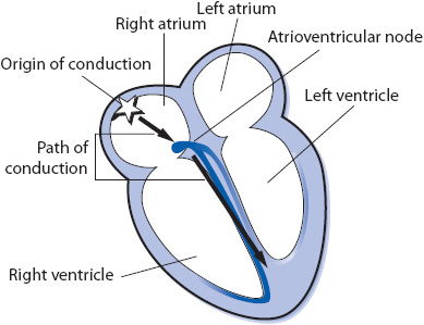
Figure 3-7. Rhythms originating in the sinus node.
• Rate: 60 to 100 beats/min.
• Rhythm: Regular.
• P waves: Precede every QRS complex; consistent in shape.
• PR interval: 0.12 to 0.20 second.
• QRS complex: 0.04 to 0.10 second.
• Conduction: Normal through atria, AV node, bundle branches, and ventricles.
• Example of normal sinus rhythm: Figure 3-8.

Figure 3-8. Normal sinus rhythm.
All aspects of sinus bradycardia are the same as normal sinus rhythm except the rate is slower. It can be a normal finding in athletes and during sleep. Sinus bradycardia may be a response to vagal stimulation, such as carotid sinus massage, ocular pressure, or vomiting. Sinus bradycardia can be caused by inferior MI, myxedema, obstructive jaundice, uremia, increased intracranial pressure, glaucoma, anorexia nervosa, and sick sinus syndrome. Sinus bradycardia can be a response to several medications, including digitalis, beta-blockers, and some calcium channel blockers.
• Rate: Less than 60 beats/min.
• Rhythm: Regular.
• P waves: Precede every QRS; consistent in shape.
• PR interval: Usually normal (0.12-0.20 second).
• QRS complex: Usually normal (0.04-0.10 second).
• Conduction: Normal through atria, AV node, bundle branches, and ventricles.
• Example of sinus bradycardia: Figure 3-9.

Figure 3-9. Sinus bradycardia.
Treatment of sinus bradycardia is not required unless the patient is symptomatic. If the arrhythmia is accompanied by hypotension, confusion, diaphoresis, chest pain, or other signs of hemodynamic compromise or by ventricular ectopy, 0.5 mg of atropine IV is the treatment of choice. Attempts are made to decrease vagal stimulation. If the arrhythmia is due to medications, they are held until their need has been reevaluated. Temporary or permanent pacing may be necessary.
Sinus tachycardia is a sinus rhythm at a rate greater than 100 beats/min. Sinus tachycardia is a normal response to exercise and emotion. Sinus tachycardia that persists at rest usually indicates some underlying problem, such as fever, acute blood loss, shock, pain, anxiety, heart failure, hypermetabolic states, or anemia. Sinus tachycardia is a normal physiologic response to a decrease in cardiac output; cardiac output is the product of heart rate and stroke volume. Sinus tachycardia can be caused by the following medications: atropine, isoproterenol, epinephrine, dopamine, dobutamine, norepinephrine, nitroprusside, and caffeine.
• Rate: Greater than 100 beats/min.
• Rhythm: Regular.
• P waves: Precede every QRS; consistent in shape; may be buried in the preceding T wave.
• PR interval: Usually normal; may be difficult to measure if P waves are buried in T waves.
• QRS complex: Usually normal.
• Conduction: Normal through atria, AV node, bundle branches, and ventricles.
• Example of sinus tachycardia: Figure 3-10.

Figure 3-10. Sinus tachycardia.
Treatment of sinus tachycardia is directed at the underlying cause. This arrhythmia is a physiologic response to a decrease in cardiac output, and it should never be ignored, especially in the cardiac patient. Because the ventricles fill with blood and the coronary arteries perfuse during diastole, persistent tachycardia can cause decreased stroke volume, decreased cardiac output, and decreased coronary perfusion secondary to the decreased diastolic time that occurs with rapid heart rates. Carotid sinus pressure may slow the heart rate temporarily and thereby help in ruling out other arrhythmias.
Sinus arrhythmia occurs when the sinus node discharges irregularly. It occurs frequently as a normal phenomenon and is commonly associated with the phases of respiration. During inspiration, the sinus node fires faster; during expiration, it slows. Digitalis toxicity may also cause this arrhythmia. Sinus arrhythmia looks like normal sinus rhythm except for the sinus irregularity.
• Rate: 60 to 100 beats/min.
• Rhythm: Irregular; phasic increase and decrease in rate, which may or may not be related to respiration.
• P waves: Precede every QRS complex; consistent in shape.
• PR interval: Usually normal.
• QRS complex: Usually normal.
• Conduction: Normal through atria, AV node, bundle branches, and ventricles.
• Example of sinus arrhythmia: Figure 3-11.

Figure 3-11. Sinus arrhythmia.
Treatment of sinus arrhythmia usually is not necessary. If the arrhythmia is thought to be because of digitalis toxicity, then digitalis is held. Atropine increases the rate and eliminates the irregularity.
Sinus arrest occurs when sinus node firing is depressed and impulses are not formed when expected. The result is an absent P wave at the expected time. The QRS complex is also missing, unless there is escape of a junctional or ventricular impulse. If only one sinus impulse fails to form, this is usually called a sinus pause. If more than one sinus impulse in a row fails to form, this is termed a sinus arrest. Because the sinus node is not forming impulses regularly as expected, the PP interval in sinus arrest is not an exact multiple of the sinus cycle. Causes of sinus arrest include vagal stimulation, carotid sinus sensitivity, and MI interrupting the blood supply to the sinus node. Drugs such as digitalis, beta-blockers, and calcium channel blockers can also cause sinus arrest.
• Rate: Usually within normal range but may be in the bradycardia range.
• Rhythm: Irregular due to absence of sinus node discharge.
• P waves: Present when sinus node is firing and absent during periods of sinus arrest. When present, they precede every QRS complex and are consistent in shape.
• PR interval: Usually normal when P waves are present.
• QRS complex: Usually normal when sinus node is functioning and absent during periods of sinus arrest, unless escape beats occur.
• Conduction: Normal through atria, AV node, bundle branches, and ventricles when sinus node is firing. When the sinus node fails to form impulses, there is no conduction through the atria.
• Example of sinus arrest: Figure 3-12.

Figure 3-12. Sinus arrest.
Treatment of sinus arrest is aimed at the underlying cause. Drugs that are thought to be responsible are discontinued and vagal stimulation is minimized. If periods of sinus arrest are frequent and cause hemodynamic compromise, 0.5 mg of atropine IV may increase the rate. Pacemaker therapy may be necessary if other forms of management fail to increase the rate to acceptable levels.
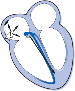
Figure 3-13. Arrhythmias originating in the atria.
A premature atrial complex (PAC) occurs when an irritable focus in the atria fires before the next sinus node impulse is due to fire. PACs can be caused by caffeine, alcohol, nicotine, heart failure (HF), pulmonary disease, interruption of atrial blood supply by myocardial ischemia or infarction, anxiety, and hypermetabolic states. PACs can also occur in normal hearts.
• Rate: Usually within normal range.
• Rhythm: Usually regular except when PACs occur, resulting in early beats. PACs usually have a noncompensatory pause (interval between the complex preceding and that following the PAC is less than two normal RR intervals) because premature depolarization of the atria by the PAC usually causes premature depolarization of the sinus node as well, thus causing the sinus node to “reset” itself.
• P waves: Precede every QRS complex. The configuration of the premature P wave differs from that of the sinus P waves because the premature impulse originates in a different part of the atria, with atrial depolarization occurring in a different pattern. Very early P waves may be buried in the preceding T wave.
• PR interval: May be normal or long depending on the prematurity of the beat; very early PACs may find the AV junction still partially refractory and unable to conduct at a normal rate, resulting in a prolonged PR interval.
• QRS complex: May be normal, aberrant (wide) or absent, depending on the prematurity of the beat. If the ventricles have repolarized completely, they will be able to conduct the early impulse normally, resulting in a normal QRS. If the PAC occurs during the relative refractory period of the AV node, bundle branches or ventricles, the impulse will conduct aberrantly and the QRS will be wide. If the PAC occurs very early during the complete refractory period of the AV node, bundle branches or ventricles, the impulse will not conduct to the ventricles and the QRS will be absent.
• Conduction: PACs travel through the atria differently from sinus impulses because they originate from a different spot; conduction through the AV node, bundle branches, and ventricles is usually normal unless the PAC is very early.
• Example of PAC: Figure 3-14A, B.
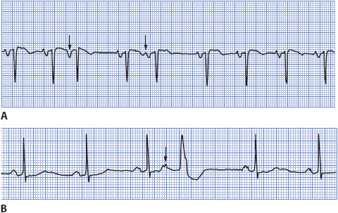
Figure 3-14. (A) PAC conducted normally in the ventricle. (B) PAC conducted aberrantly in the ventricle.
Treatment of PACs usually is not necessary because they do not cause hemodynamic compromise. Frequent PACs may precede more serious arrhythmias such as atrial fibrillation. Treatment is directed at the cause. Drugs such as beta-blockers, disopyramide, procainamide, flecainide, and propafenone can be used to suppress atrial activity, but this is rarely necessary.
Wandering atrial pacemaker (WAP) refers to rhythms that exhibit varying P-wave morphology as the site of impulse formation shifts from the sinus node to various sites in the atria or into the AV junction. This occurs when two (usually sinus and junctional) or more supraventricular pacemakers compete with each other for control of the heart. Because the rates of these competing pacemakers are almost identical, it is common to have atrial fusion occur as the atria are activated by more than one wave of depolarization at a time, resulting in varying P-wave morphology. Wandering atrial pacemaker can be due to increased vagal tone that slows the sinus pacemaker or to enhanced automaticity in atrial or junctional pacemaker cells, causing them to compete with the sinus node for control.
• Rate: 60 to 100 beats/min. If the rate is faster than 100 beats/min, it is called multifocal atrial tachycardia (MAT).
• Rhythm: May be slightly irregular.
• P waves: Varying shapes (upright, flat, inverted, notched) as impulses originate in different parts of the atria or junction. At least three different P-wave shapes should be seen.
• PR interval: May vary depending on proximity of the pacemaker to the AV node.
• QRS complex: Usually normal.
• Conduction: Conduction through the atria varies as they are depolarized from different spots. Conduction through the bundle branches and ventricles is usually normal.
• Example of WAP: Figure 3-15.

Figure 3-15. Wandering atrial pacemaker.
Treatment of WAP usually is not necessary. If slow heart rates lead to symptoms, atropine can be given. Treatment of MAT is directed toward eliminating the cause, including hypoxia and electrolyte imbalances. Antiarrhythmic therapy is often ineffective. Beta-blockers, verapamil, flecainide, amiodarone, and magnesium may be successful.
Atrial tachycardia (AT) is a rapid atrial rhythm occurring at a rate of 120 to 250 beats/min and can be due to abnormal automaticity or to reentry within the atrium (Figure 3-16). When the arrhythmia abruptly starts and terminates, it is called paroxysmal atrial tachycardia. Rapid atrial rate can be caused by emotions, caffeine, tobacco, alcohol, fatigue, or sympathomimetic drugs. Whenever the atrial rate is rapid, the AV node begins to block some of the impulses attempting to travel through it to protect the ventricles from excessively rapid rates. In normal healthy hearts, the AV node can usually conduct each atrial impulse up to rates of about 180 to 200 beats/min. In patients with cardiac disease or who are on AV nodal blocking drugs such as digitalis, beta blockers or calcium channel blockers, the AV node may not be able to conduct each impulse and AT with block occurs. Atrial tachycardia with block may indicate digitalis toxicity.
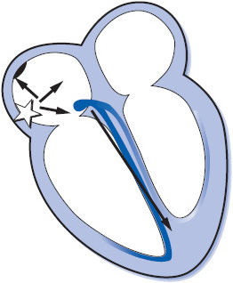
Figure 3-16. Atrial tachycardia.
• Rate: Atrial rate is 120 to 250 beats/min.
• Rhythm: Regular unless there is variable block at the AV node.
• P waves: Differ in shape from sinus P waves because they are ectopic. Precede each QRS complex but may be hidden in preceding T wave. When block is present, more than one P wave will appear before each QRS complex.
• PR interval: May be shorter than normal but often difficult to measure because of hidden P waves.
• QRS complex: Usually normal but may be wide if aberrant conduction is present.
• Conduction: Usually normal through the AV node and into the ventricles. In atrial tachycardia with block, some atrial impulses do not conduct into the ventricles. Aberrant ventricular conduction may occur if atrial impulses are conducted into the ventricles while the bundle branches or ventricles are still partially refractory.
• Example of atrial tachycardia: Figure 3-17.

Figure 3-17. Atrial tachycardia.
Treatment of AT is directed at eliminating the cause, if possible, controlling the ventricular rate, and reestablishing sinus rhythm. If the patient is hemodynamically unstable due to a rapid AT, cardioversion can be attempted, although automatic ATs usually do not respond to cardioversion. Some ATs may terminate with IV adenosine, but more often IV verapamil or diltiazem, or an IV beta-blocker, is used for acute therapy to slow the ventricular rate, and they may occasionally terminate the AT. Other drugs that can be tried to suppress AT are procainamide, flecainide, propafenone, amiodarone, or sotalol. Catheter ablation is a class I recommendation for preventing recurrent AT. See Table 3-4 for class I recommendations for management of AT.
TABLE 3-4. GUIDELINES FOR MANAGEMENT OF SUPRAVENTRICULAR ARRHYTHMIAS (CLASS I RECOMMENDATIONS ONLY)

In atrial flutter (Figure 3-18) the atria are depolarized at rates of 250 to 350 times/min. Classic or typical atrial flutter is due to a fixed reentry circuit in the right atrium around which the impulse circulates in a counterclockwise direction, resulting in negative flutter waves in leads II and III and an atrial rate between 250 and 350 beats/min (most commonly 300 beats/min). At such rapid atrial rates, the AV node usually blocks at least half of the impulses to protect the ventricles from excessive rates. Causes of atrial flutter include rheumatic heart disease, atherosclerotic heart disease, thyrotoxicosis, heart failure, and myocardial ischemia or infarction. Because the ventricular rate in atrial flutter can be quite fast, symptoms associated with decreased cardiac output can occur. Mural thrombi may form in the atria due to the fact that there is no strong atrial contraction, and blood stasis occurs, leading to a risk of systemic or pulmonary emboli.
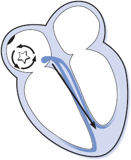
Figure 3-18. Atrial flutter.
• Rate: Atrial rate varies between 250 and 350 beats/min, most commonly 300. Ventricular rate varies depending on the amount of block at the AV node. New onset atrial flutter usually has a ventricular rate around 150 beats/min, and rarely 300 beats/min if 1:1 conduction occurs to the ventricles. With AV nodal blocking drug therapy, the ventricular rate is usually in the normal range, commonly around 75 beats/min.
• Rhythm: Atrial rhythm is regular. Ventricular rhythm may be regular or irregular because of varying AV block.
• F waves: F waves (flutter waves) are seen, characterized by a very regular, “sawtooth” pattern. One F wave is usually hidden in the QRS complex, and when 2:1 conduction occurs, F waves may not be readily apparent.
• FR interval (flutter wave to the beginning of the QRS complex): May be consistent or may vary.
• QRS complex: Usually normal; aberration can occur.
• Conduction: Usually normal through the AV node and ventricles.
• Example of atrial flutter: Figure 3-19A, B.
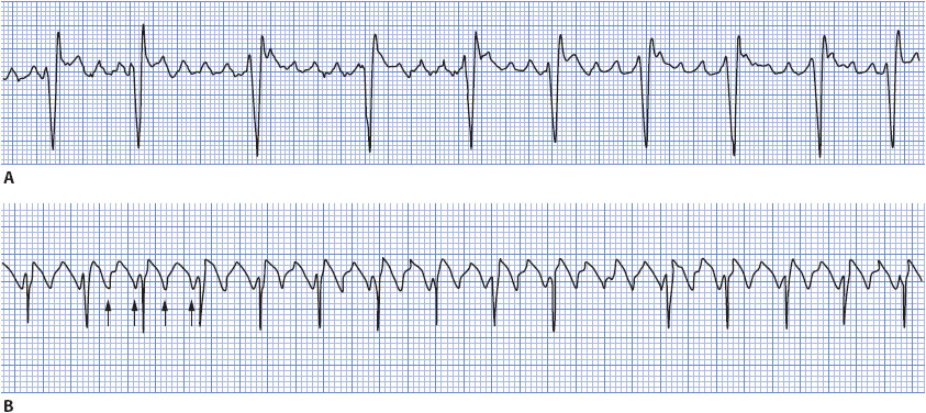
Figure 3-19. (A) Atrial flutter with 4:1 and 5:1 conduction. (B) Atrial flutter with 2:1 conduction.
The immediate goal of treatment depends on the hemodynamic consequences of the arrhythmia. Ventricular rate control is the priority if cardiac output is markedly compromised due to rapid ventricular rates. Electrical (direct current) cardioversion may be necessary as an immediate treatment, especially if 1:1 conduction occurs. IV calcium channel blockers (verapamil or diltiazem) or beta-blockers can be used for ventricular rate control. Conversion to sinus rhythm can be accomplished by electrical cardioversion, drug therapy, or overdrive atrial pacing. Drug therapy for atrial flutter is the same as that for atrial fibrillation and is discussed in the next section on atrial fibrillation. Drugs that slow the atrial rate, like flecainide or propafenone, should not be used unless the ventricular rate has been controlled with an AV nodal blocking agent (a calcium channel blocker, beta-blocker, or digitalis). The danger of giving these drugs alone is that the atrial rate may decrease from 300 beats/min to a slower rate, making it possible for the AV node to conduct each impulse and resulting in even faster ventricular rates (Table 3-4).
Atrial fibrillation (AF) is an extremely rapid and disorganized pattern of depolarization in the atria, and is the most common arrhythmia seen in clinical practice (Figure 3-20). Atrial fibrillation commonly occurs in the presence of atherosclerotic or rheumatic heart disease, thyroid disease, HF, cardiomyopathy, valve disease, pulmonary disease, MI, congenital heart disease, and after cardiac surgery. Atrial fibrillation is classified into three categories: paroxysmal, episodes that last < 7 days and often < 24 hours; persistent, episodes that last > 7 days and often require electrical or pharmacological cardioversion; and permanent, longstanding AF that is usually present for more than a year and has failed cardioversion or in which cardioversion is considered futile. The term recurrent is used when the patient has two or more episodes of AF, and the term lone AF is used when AF occurs in the absence of cardiac disease or any other known cause (usually in people < 60 years of age). Nonvalvular AF occurs in patients without mitral valve disease, prosthetic valve, or history of valve surgery.
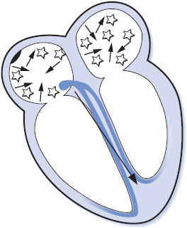
Figure 3-20. Atrial fibrillation.
Atrial fibrillation has several adverse consequences that require prompt recognition and treatment in order to prevent complications:
1. Decreased cardiac output due to loss of atrial kick, rapid ventricular rate, and irregular ventricular rhythm. Cardiac output is dependent on adequate ventricular filling, and the loss of atrial contraction and the rapid ventricular rate that commonly occurs in AF contribute to reduced ventricular filling.
2. Tachycardia-induced cardiomyopathy can occur whenever the ventricular rate is rapid for a prolonged period of time. This is more common in asymptomatic patients who are unaware that they are in AF.
3. Thromboembolism because of formation of clots in the fibrillating atria, usually in the left atrial appendage. Stroke is the most common and potentially devastating embolic event, but pulmonary embolus and embolization to any other part of the body can also occur.
• Rate: Atrial rate is 400 to 600 beats/min or faster. Ventricular rate varies depending on the amount of block at the AV node. In new AF, the ventricular response is usually quite rapid, 160 to 200 beats/min; in treated atrial fibrillation, the ventricular rate is controlled in the normal range of 60 to 100 beats/min.
• Rhythm: Irregular; one of the distinguishing features of AF is the marked irregularity of the ventricular response.
• F waves: Not present; atrial activity is chaotic with no formed atrial impulses visible; irregular F waves are often seen, and vary in size from coarse to very fine.
• PR interval: Not measurable; there are no P waves.
• QRS complex: Usually normal; aberration is common.
• Conduction: Conduction within the atria is disorganized and follows a very irregular pattern. Most of the atrial impulses are blocked within the AV junction. Those impulses that are conducted through the AV junction are usually conducted normally through the ventricles. If an atrial impulse reaches the bundle branch system during its refractory period, aberrant intraventricular conduction can occur.
• Example of atrial fibrillation: Figure 3-21 A, B.
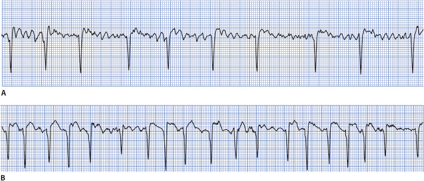
Figure 3-21. (A) Atrial fibrillation with a controlled ventricular response. (B) Atrial fibrillation with an uncontrolled ventricular response.
Treatment of AF is directed toward eliminating the cause, controlling ventricular rate, restoring and maintaining sinus rhythm, and preventing thromboembolism. The American College of Cardiology, American Heart Association, European Society of Cardiology, and the Heart Rhythm Society have collaborated to publish guidelines for the management of AF. The American Heart Association and American Stroke Association released a science advisory on oral antithrombotic drugs for the prevention of stroke in nonvalvular atrial fibrillation in 2011. See Table 3-5 for the guidelines class I recommendations for management of AF.
TABLE 3-5. GUIDELINES FOR MANAGEMENT OF ATRIAL FIBRILLATION AND ATRIAL FLUTTER (CLASS I RECOMMENDATIONS ONLY)

Ventricular rate control is aimed at improving hemodynamics and relieving symptoms. New onset AF often results in a very rapid ventricular rate that can be mildly to moderately symptomatic or cause extreme hemodynamic instability. Patients with Wolff-Parkinson-White (WPW) syndrome have an accessory pathway that can conduct atrial fibrillation impulses directly into the ventricle via the accessory pathway, resulting in an extremely rapid ventricular rate that can cause ventricular fibrillation and sudden cardiac death (see Chapter 18). In the unstable patient, ventricular rate control is a priority, and electrical cardioversion may be necessary if the patient is hemodynamically unstable because of rapid ventricular rate. Intravenous calcium channel blockers (eg, diltiazem, verapamil) and beta-blockers are commonly used in the acute situation for ventricular rate control but should be used with caution in the presence of heart failure or hypotension and are contraindicated if WPW is present. Beta-blockers, calcium channel blockers, and digitalis can be used orally for long-term rate control.
Rhythm control is restoration of sinus rhythm using pharmacologic or electrical cardioversion, and maintenance of sinus rhythm using antiarrhythmic drugs. Antiarrhythmic drugs with a class I recommendation for pharmacological cardioversion of AF are flecainide, dofetilide, propafenone, and ibutilide; amiodarone is a class IIa recommendation. Drug therapy is most effective in restoring sinus rhythm when started within 7 days of AF onset. There are no drugs with a class I recommendation for maintenance of sinus rhythm, but several antiarrhythmics can be effective, including amiodarone, dofetilide, dronedarone, flecainide, propafenone, and sotalol. Oral beta-blocker therapy is often used to try to prevent postoperative AF in patients undergoing cardiac surgery. Refer to specific drug guidelines for patient selection criteria.
Preventing thromboembolism is a goal in all patients with AF regardless of rhythm or rate control strategy. Antithrombotic therapy is recommended for all patients with AF, except those with lone AF or those with contraindications. The risk of stroke must be weighed against the risk of bleeding when considering drug therapy for thromboembolism prevention. The CHADS2 risk index is commonly used to assess stroke risk in AF patients: C = congestive heart failure, H = hypertension, A = age > 75 years, D = diabetes, and S = history of stroke or TIA. CHADS2 assigns 2 points for a history of stroke or TIA and 1 point for each of the other risk factors. Oral anticoagulation with warfarin to maintain INR between 2.0 and 3.0 (target INR = 2.5) is the usual recommendation for patients with a CHADS2 score of 2 or higher. Aspirin or aspirin with clopidogrel is an alternative in low risk patients or those with contraindications. Dabigatran, rivaroxaban, and apixaban are three new oral drugs recently approved by the FDA for stroke prevention in patients with nonvalvular AF. Table 3-5 contains class I recommendations for thromboembolism prevention in patients with AF or atrial flutter.
Radiofrequency (RF) catheter ablation and surgical management of AF include AV node ablation, pulmonary vein ablation, surgical or ablation Maze procedures, and occlusion or surgical removal of the left atrial appendage. These procedures are briefly described here.
Radiofrequency AV node ablation is the most common nonpharmacologic method of rate control in AF and is usually done only when drug therapy for rate control is ineffective or not tolerated. RF energy is directed at the AV node to heat the tissue and destroy its ability to conduct impulses to the ventricle. This procedure results in complete AV block and requires a ventricular pacemaker implant to maintain an adequate ventricular rate. AV node ablation does not stop atrial fibrillation; therefore, patients must be chronically anticoagulated to prevent stroke.
Radiofrequency ablation of AF trigger sites in the pulmonary veins or atria is the mainstay of ablation therapy for AF. The most common site of AF triggers is the first 2-4 cm inside the pulmonary veins leading into the left atrium, although triggers can be present in multiple sites within both atria. The most successful procedures are segmental ostial pulmonary vein isolation (PVI) and circumferential PVI. In segmental ostial PVI, specific sites of electrical conduction in the ostia of the pulmonary veins are ablated. In circumferential PVI, continuous ablation lesions encircle the ostia of all four pulmonary veins, usually in two pairs (ie, one circle of lesions around the left pulmonary veins and another circle around the right pulmonary veins). These ablation lesions completely isolate the pulmonary veins from the atrial myocardium and prevent conduction from trigger sites in to the atria.
The Cox-Maze III procedure involves creation of multiple incisions within both atria using the “cut and sew” technique during cardiac surgery. The incisions create scars in the atria that direct the impulse from the sinus node to the AV node through both atria in an orderly fashion and prevent reentry of impulses that could lead to AF. Similar scars can be created using bipolar RF ablation clamps (Cox-Maze IV procedure), which still requires cardiac surgery and cardiopulmonary bypass. Catheter-based RF ablation procedures create the lesions from the endocardial approach and are done percutaneously in the electrophysiology laboratory rather than requiring surgery.
Left atrial appendage (LAA) amputation is done along with surgical Cox-Maze procedures as well as with mitral valve procedures to reduce the likelihood of thromboembolism, since most clots develop in the LAA during AF. Left atrial appendage occlusion devices can be inserted via the right femoral vein and into the LAA through a trans-septal approach and expanded within the LAA to seal it from the rest of the atrium, thus trapping clots and preventing them from embolizing.
A supraventricular tachycardia by definition is any rhythm at a rate faster than 100 beats/min that originates above the ventricle or utilizes the atria or AV junction as part of the circuit that maintains the tachycardia. Technically, this can include sinus tachycardia, AT, atrial flutter, atrial fibrillation, and junctional tachycardia. However, the term SVT is meant to be used to describe a regular, narrow QRS tachycardia in which the exact mechanism cannot be determined from the surface ECG. If P waves or atrial activity such a fibrillation or flutter waves can be clearly seen, then the mechanism can usually be identified. Occasionally in AT the P waves are hidden in preceding T waves and in that case use of the term SVT is appropriate.
The two most common arrhythmias for which the term SVT is appropriate are AV nodal reentry tachycardia (AVNRT) and circus movement tachycardia (CMT) that occurs when an accessory pathway is present, such as in WPW. Another term used to describe CMT is AV reentry tachycardia (AVRT) but CMT is used here to prevent confusion between these two common arrhythmias. The mechanisms of these SVTs are described in detail in Chapter 18, Advanced Arrhythmia Interpretation. ECG characteristics of both SVTs are very similar and described here.
• Rate: 140-250 beats/minute.
• Rhythm: Regular.
• P waves: Usually not visible. In AVNRT, the P wave is hidden in the QRS or barely peeking out at the end of the QRS. In CMT, the P wave is usually present in the ST segment, but is often not visible.
• PR interval: Not measurable, since P waves are usually not visible.
• QRS complex: Usually normal.
• Conduction: In AVNRT, the impulse travels in a small circuit that includes the AV node as one limb of the circuit and a slower conducting pathway just outside the AV node as the second limb of the circuit. The impulse depolarizes the atria in a retrograde direction at the same time as it depolarizes the ventricles through the normal His-Purkinje system, resulting in a regular narrow QRS tachycardia. In CMT, the impulse follows a reentry circuit that includes the atria, AV node, ventricles, and accessory pathway. The most common type of CMT is called orthodromic CMT, in which the impulse travels from atria to ventricles through the normal AV node and His-Purkinje system, then back to the atria from the ventricles through the accessory pathway. This results in a regular, narrow QRS tachycardia because the ventricles are depolarized via the normal conduction system. If the circuit reverses direction and the ventricles depolarize through conduction down the accessory pathway, this is called antidromic CMT, and the resulting tachycardia has a wide QRS complex.
• Example of SVT: See Figure 3-23 A, B.

Figure 3-23. (A) SVT at a rate of 190 beats/min found to be AVNRT at electrophysiology study. (B) SVT at a rate of 214 found to be CMT at electrophysiology study.
These SVTs are usually well tolerated and often paroxysmal in nature. If the ventricular rate is very rapid and sustained, symptoms such as palpitations, dizziness, or syncope can occur.
Vagal maneuvers such as carotid sinus massage, Valsalva’s maneuver, gagging or coughing, drinking ice water, or putting the face in ice water may be effective in terminating the tachycardia. Adenosine (6 mg given rapidly IV, may repeat with 12 mg if necessary) is the most effective drug to terminate the tachycardia. Drugs that slow AV conduction, like calcium channel blockers (diltiazem, verapamil) or beta-blockers, can terminate tachycardia and can be used long term to prevent recurrences. Synchronized cardioversion can be used if drugs are contraindicated or fail to terminate tachycardia. Radiofrequency ablation offers a cure for AVNRT and CMT. See Table 3-4 for class I recommendations for management of supraventricular tachycardias.
Cells surrounding the AV node in the AV junction are capable of initiating impulses and controlling the heart rhythm (Figure 3-24). Junctional beats and junctional rhythms can appear in any of three ways on the ECG depending on the location of the junctional pacemaker and the speed of conduction of the impulse into the atria and ventricles:
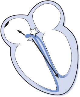
Figure 3-24. Arrhythmias originating in the AV junction.
• When a junctional focus fires, the wave of depolarization spreads backward (retrograde) into the atria as well as forward (antegrade) into the ventricles. If the impulse arrives in the atria before it arrives in the ventricles, the ECG shows a P wave (usually inverted because the atria are depolarizing from bottom to top) followed immediately by a QRS complex as the impulse reaches the ventricles. In this case the PR interval is very short, usually 0.10 second or less.
• If the junctional impulse reaches both the atria and the ventricles at the same time, only a QRS is seen on the ECG because the ventricles are much larger than the atria and only ventricular depolarization will be seen, even though the atria are also depolarizing.
• If the junctional impulse reaches the ventricles before it reaches the atria, the QRS precedes the P wave on the ECG. Again, the P wave is usually inverted because of retrograde atrial depolarization, and the RP interval (distance from the beginning of the QRS to the beginning of the following P wave) is short.
Premature junctional complexes (PJCs) are due to an irritable focus in the AV junction. Irritability can be because of coronary heart disease or MI disrupting blood flow to the AV junction, nicotine, caffeine, emotions, or drugs such as digitalis.
• Rate: 60 to 100 beats/min or whatever the rate of the basic rhythm.
• Rhythm: Regular except for occurrence of premature beats.
• P waves: May occur before, during, or after the QRS complex of the premature beat and are usually inverted.
• PR interval: Short, usually 0.10 second or less when P waves precede the QRS.
• QRS complex: Usually normal but may be aberrant if the PJC occurs very early and conducts into the ventricles during the refractory period of a bundle branch.
• Conduction: Retrograde through the atria; usually normal through the ventricles.
• Example of a PJC: Figure 3-25.

Figure 3-25. Premature junctional complexes.
Treatment is not necessary for PJCs.
Junctional rhythms can occur if the sinus node rate falls below the rate of the AV junctional pacemakers or when atrial conduction through the AV junction has been disrupted. Junctional rhythms commonly occur from digitalis toxicity or following inferior MI owing to disruption of blood supply to the sinus node and the AV junction. These rhythms are classified according to their rate. Junctional rhythm usually occurs at a rate of 40 to 60 beats/min, accelerated junctional rhythm occurs at a rate of 60 to 100 beats/min, and junctional tachycardia occurs at a rate of 100 to 250 beats/min.
• Rate: Junctional rhythm, 40 to 60 beats/min; accelerated junctional rhythm, 60 to 100 beats/min; junctional tachycardia, 100 to 250 beats/min.
• Rhythm: Regular.
• P waves: May precede or follow QRS.
• PR interval: Short, 0.10 second or less.
• QRS complex: Usually normal.
• Conduction: Retrograde through the atria; normal through the ventricles.
• Example of junctional rhythm and accelerated junctional rhythm: Figure 3-26A, B.
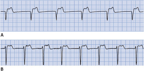
Figure 3-26. (A) Junctional rhythm. (B) Accelerated junctional rhythm.
Treatment of junctional rhythm rarely is required unless the rate is too slow or too fast to maintain adequate cardiac output. If the rate is slow, atropine is given to increase the sinus rate and override the junctional focus or to increase the rate of firing of the junctional pacemaker. If the rate is fast, drugs such as verapamil, propranolol, or beta-blockers may be effective in slowing the rate or terminating the arrhythmia. Because digitalis toxicity is a common cause of junctional rhythms, the drug should be held.
Ventricular arrhythmias originate in the ventricular muscle or Purkinje system and are considered to be more dangerous than other arrhythmias because of their potential to initiate VT and severely decrease cardiac output (Figure 3-27). However, as with any arrhythmia, ventricular rate is a key determinant of how well a patient can tolerate a ventricular rhythm. Ventricular rhythms can range in severity from mild, well-tolerated rhythms to pulseless rhythms leading to sudden cardiac death.
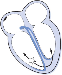
Figure 3-27. Arrhythmias originating in the ventricles.
Premature ventricular complexes (PVCs) are caused by premature depolarization of cells in the ventricular myocardium or Purkinje system or to reentry in the ventricles. PVCs can be caused by hypoxia, myocardial ischemia, hypokalemia, acidosis, exercise, increased levels of circulating catecholamines, digitalis toxicity, caffeine, and alcohol, among other causes. PVCs increase with aging and are more common in people with coronary disease, valve disease, hypertension, cardiomyopathy, and other forms of heart disease. PVCs are not dangerous in people with normal hearts but are associated with higher mortality rates in patients with structural heart disease or acute MI, especially if left ventricular function is reduced. PVCs are considered potentially malignant when they occur more frequently than 10 per hour or are repetitive (occur in pairs, triplets, or more than three in a row) in patients with coronary disease, previous MI, cardiomyopathy, and reduced ejection fraction.
• Rate: 60 to 100 beats/min or the rate of the basic rhythm.
• Rhythm: Irregular because of the early beats.
• P waves: Not related to the PVCs. Sinus rhythm is usually not interrupted by the premature beats, so sinus P waves can often be seen occurring regularly throughout the rhythm. P waves may occasionally follow PVCs due to retrograde conduction from the ventricle backward through the atria. These P waves are inverted.
• PR interval: Not present before most PVCs. If a P wave happens, by coincidence, to precede a PVC, the PR interval is short.
• QRS complex: Wide and bizarre; greater than 0.10 second in duration. These may vary in morphology (size, shape) if they originate from more than one focus in the ventricles (multifocal PVCs).
• Conduction: Impulses originating in the ventricles conduct through the ventricles from muscle cell to muscle cell rather than through Purkinje fibers, resulting in wide QRS complexes. Some PVCs may conduct retrograde into the atria, resulting in inverted P waves following the PVC. When the sinus rhythm is undisturbed by PVCs, the atria depolarize normally.
• Example of PVCs: Figure 3-28A, B.
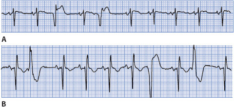
Figure 3-28. Premature ventricular complexes.
The significance of PVCs depends on the clinical setting in which they occur. Many people have chronic PVCs that do not need to be treated, and most of these people are asymptomatic. There is no evidence that suppression of PVCs reduces mortality, especially in patients with no structural heart disease. If PVCs cause bothersome palpitations, patients are told to avoid caffeine, tobacco, other stimulants, and try stress reduction techniques. Low-dose beta-blockers may reduce PVC frequency and the perception of palpitations and can be used for symptom relief. In the setting of an acute MI or myocardial ischemia, PVCs may be precursors of more dangerous ventricular arrhythmias, especially when they occur near the apex of the T wave (R on T PVCs). Unless PVCs result in hemodynamic instability or symptomatic VT, most providers elect not to treat them. If PVCs are to be treated, IV lidocaine or amiodarone are the drugs usually used. Procainamide can also be used IV for acute control. Beta-blockers are often effective in suppressing repetitive PVCs and have become the drugs of choice for treating post-MI PVCs that are symptomatic. Several antiarrhythmic drugs are effective in reducing the frequency of PVCs but are not recommended due to the risk of proarrhythmia and their association with sudden cardiac death in patients with structural heart disease.
Ventricular rhythm occurs when an ectopic focus in the ventricle fires at a rate less than 50 beats/min. This rhythm occurs as an escape rhythm when the sinus node and junctional tissue fail to fire or fail to conduct their impulses to the ventricle. Accelerated ventricular rhythm occurs when an ectopic focus in the ventricles fires at a rate of 50 to 100 beats/min. The causes of this accelerated ventricular rhythm are similar to those of VT, but accelerated ventricular rhythm commonly occurs in the presence of inferior MI when the rate of the sinus node slows below the rate of the latent ventricular pacemaker. Accelerated ventricular rhythm is a common arrhythmia after thrombolytic therapy, when reperfusion of the damaged myocardium occurs.
• Rate: Less than 50 beats/min for ventricular rhythm and 50 to 100 beats/min for accelerated ventricular rhythm.
• Rhythm: Usually regular.
• P waves: May be seen but at a slower rate than the ventricular focus, with dissociation from the QRS complex.
• PR interval: Not measured.
• QRS complex: Wide and bizarre.
• Conduction: If sinus rhythm is the basic rhythm, atrial conduction is normal. Impulses originating in the ventricles conduct via muscle cell-to-cell conduction, resulting in the wide QRS complex.
• Example of escape ventricular rhythm and accelerated ventricular rhythm: Figure 3-29 A, B.
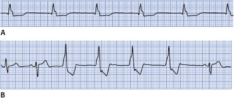
Figure 3-29. (A) Escape ventricular rhythm. (B) Accelerated ventricular rhythm.
The treatment of accelerated ventricular rhythm depends on its cause and how well it is tolerated by the patient. This arrhythmia alone is usually not harmful because the ventricular rate is within normal limits and usually adequate to maintain cardiac output. Suppressive therapy is rarely used because abolishing the ventricular rhythm may leave an even less desirable heart rate. If the patient is symptomatic because of the loss of atrial kick, atropine can be used to increase the rate of the sinus node and overdrive the ventricular rhythm. If the ventricular rhythm is an escape rhythm, then treatment is directed toward increasing the rate of the escape rhythm or pacing the heart temporarily. Usually, accelerated ventricular rhythm is transient and benign and does not require treatment.
Ventricular tachycardia (VT) is a rapid ventricular rhythm at a rate greater than 100 beats/min. VT can be classified according to: (1) duration, nonsustained (lasts less than 30 seconds), sustained (lasts longer than 30 seconds), or incessant (VT present most of the time); and (2) morphology (ECG appearance of QRS complexes), monomorphic (QRS complexes have the same shape during tachycardia), polymorphic (QRS complexes vary randomly in shape), or bidirectional (alternating upright and negative QRS complexes during tachycardia). Polymorphic VT that occurs in the presence of a long QT interval is called torsades de pointes (meaning “twisting of the points”). The most common cause of VT is coronary artery disease, including acute ischemia, acute MI, and prior MI. Other causes include cardiomyopathy, valvular heart disease, congenital heart disease, arrhythmogenic right ventricular dysplasia, cardiac tumors, cardiac surgery, and the proarrhythmic effects of many drugs. See Chapter 18 for more information on ventricular tachycardias and the differential diagnosis of wide QRS tachycardias.
• Rate: Ventricular rate is faster than 100 beats/min.
• Rhythm: Monomorphic VT is usually regular, polymorphic VT can be irregular.
• P waves: Dissociated from QRS complexes. If sinus rhythm is the underlying basic rhythm, they are regular. P waves may be seen but are not related to QRS complexes. P waves are often buried within QRS complexes.
• PR interval: Not measurable because of dissociation of P waves from QRS complexes.
• QRS complex: Usually 0.12 second or more in duration.
• Conduction: Impulse originates in one ventricle and spreads via muscle cell-to-cell conduction through both ventricles. There may be retrograde conduction through the atria, but more often the sinus node continues to fire regularly and depolarize the atria normally.
• Example of VT: Figure 3-30.

Figure 3-30. Monomorphic ventricular tachycardia.
Immediate treatment of VT depends on how well the rhythm is tolerated by the patient. The two main determinants of patient tolerance of any tachycardia are ventricular rate and underlying left ventricular function. VT can be an emergency if cardiac output is severely decreased because of a very rapid rate or poor left ventricular function.
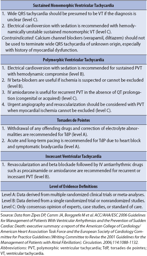
Hemodynamically unstable VT is treated with synchronized cardioversion. If VT is pulseless then immediate defibrillation is required. VT that is hemodynamically stable can be treated with drug therapy. Amiodarone is often the drug of choice but lidocaine or procainamide can also be used. Drugs used to treat VT on a long-term basis include amiodarone, sotalol, and beta-blockers. Some VTs can be treated with radiofrequency catheter ablation to abolish the ectopic focus. The implantable cardioverter defibrillator is frequently used for recurrent VT in patients with reduced ejection fractions or drug refractory VT. See Table 3-6 for class I recommendations for management of ventricular arrhythmias.
TABLE 3-6. GUIDELINES FOR MANAGEMENT OF VENTRICULAR ARRHYTHMIAS (CLASS I RECOMMENDATIONS ONLY)
Ventricular fibrillation (VF) is rapid, ineffective quivering of the ventricles and is fatal without immediate treatment (Figure 3-31). Electrical activity originates in the ventricles and spreads in a chaotic, irregular pattern throughout both ventricles. There is no cardiac output or palpable pulse with VF.

Figure 3-31. Ventricular fibrillation.
• Rate: Rapid, uncoordinated, ineffective.
• Rhythm: Chaotic, irregular.
• P waves: None seen.
• PR interval: None.
• QRS complex: No formed QRS complexes seen; rapid, irregular undulations without any specific pattern.
• Conduction: Multiple ectopic foci firing simultaneously in ventricles and depolarizing them irregularly and without any organized pattern. Ventricles are not contracting.
• Example of ventricular fibrillation: Figure 3-32.

Figure 3-32. Ventricular fibrillation.
Ventricular fibrillation requires immediate defibrillation. Synchronized cardioversion is not possible because there are no formed QRS complexes on which to synchronize the shock. Cardiopulmonary resuscitation (CPR) must be performed until a defibrillator is available, and then defibrillation at 200 J (biphasic defibrillation) or 360 J (monophasic defibrillation) is recommended followed by CPR and drug therapy. Antiarrhythmic agents such as lidocaine, amiodarone, or magnesium are commonly used in an effort to convert VF. Once the rhythm has converted, maintenance therapy with IV antiarrhythmic agents is continued. Beta-blockers and amiodarone appear to be the most effective agents for long-term drug therapy options. The implantable cardioverter defibrillator has become the standard of care for survivors of VF that occurs in the absence of acute ischemia.
Ventricular asystole is the absence of any ventricular rhythm: no QRS complex, no pulse, and no cardiac output (Figure 3-33). Ventricular asystole is always fatal unless the cause can be identified and treated immediately. If atrial activity is still present the term ventricular standstill is used.
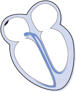
Figure 3-33. Ventricular asystole.
• Rate: None.
• Rhythm: None.
• P waves: May be present if the sinus node is functioning.
• PR interval: None.
• QRS complex: None.
• Conduction: Atrial conduction may be normal if the sinus node is functioning. There is no conduction into the ventricles.
• Example of ventricular asystole: Figure 3-34.

Figure 3-34. Ventricular asystole.
Cardiopulmonary resuscitation must be initiated immediately if the patient is to survive. IV epinephrine and vasopressin are the only drugs currently recommended for treating asystole. The cause of asystole should be determined and treated as rapidly as possible to improve the chance of survival. Asystole has a very poor prognosis despite the best resuscitation efforts because it usually represents extensive myocardial ischemia or severe underlying metabolic problems. Pacing and atropine are no longer recommended for treatment for asystole.
The term atrioventricular block is used to describe arrhythmias in which there is delayed or failed conduction of supraventricular impulses into the ventricles. AV blocks have been classified according to location of the block and severity of the conduction abnormality.
First-degree AV block is defined as prolonged AV conduction time of supraventricular impulses into the ventricles (Figure 3-35). This delay usually occurs in the AV node, and all impulses conduct to the ventricles, but with delayed conduction times. First-degree AV block can be due to coronary heart disease, rheumatic heart disease, or administration of digitalis, beta-blockers, or calcium channel blockers. First-degree AV block can be normal in people with slow heart rates or high vagal tone.
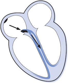
Figure 3-35. First-degree AV block.
• Rate: Can occur at any sinus rate, usually 60 to 100 beats/min.
• Rhythm: Regular.
• P waves: Normal; precede every QRS complex.
• PR interval: Prolonged above 0.20 second.
• QRS complex: Usually normal.
• Conduction: Normal through the atria, delayed through the AV node, and normal through the ventricles.
• Example of first-degree AV block: Figure 3-36.

Figure 3-36. First-degree AV block.
Treatment of first-degree AV block is usually not required, but the rhythm should be observed for progression to more severe block.
Second-degree AV block occurs when one atrial impulse at a time fails to be conducted to the ventricles. Second-degree AV block can be divided into two distinct categories: type I block, occurring in the AV node, and type II block, occurring below the AV node in the bundle of His or bundle-branch system (Figure 3-37).
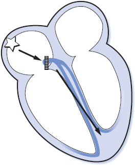
Figure 3-37. Type I second-degree AV block.
Type I second-degree AV block, often referred to as Wenckebach block, is a progressive increase in conduction times of consecutive atrial impulses into the ventricles until one impulse fails to conduct, or is “dropped.” The PR intervals gradually lengthen until one P wave fails to conduct and is not followed by a QRS complex, resulting in a pause, after which the cycle repeats itself. This type of block is commonly associated with inferior MI, coronary heart disease, aortic valve disease, mitral valve prolapse, atrial septal defects, and administration of digitalis, beta-blockers, or calcium channel blockers.
• Rate: Can occur at any sinus or atrial rate.
• Rhythm: Irregular. Overall appearance of the rhythm demonstrates “group beating.”
• P waves: Normal. Some P waves are not conducted to the ventricles, but only one at a time fails to conduct to the ventricle.
• PR interval: Gradually lengthens on consecutive beats. The PR interval preceding the pause is longer than that following the pause (unless 2:1 conduction is present).
• QRS complex: Usually normal unless there is associated bundle branch block.
• Conduction: Normal through the atria; progressively delayed through the AV node until an impulse fails to conduct. Ventricular conduction is normal. Conduction ratios can vary, with ratios as low as 2:1 (every other P wave is blocked) up to high ratios such as 15:14 (every 15th P wave is blocked).
• Example of second-degree AV block type I: Figure 3-38.

Figure 3-38. Second-degree AV block, type I.
Treatment of type I second-degree AV block depends on the conduction ratio, the resulting ventricular rate, and the patient’s tolerance for the rhythm. If ventricular rates are slow enough to decrease cardiac output, the treatment is atropine to increase the sinus rate and speed conduction through the AV node. At higher conduction ratios where the ventricular rate is within a normal range, no treatment is necessary. If the block is due to digitalis, calcium channel blockers, or beta-blockers, those drugs are held. This type of block is usually temporary and benign, and seldom requires pacing, although temporary pacing may be needed when the ventricular rate is slow.
Type II second-degree AV block is sudden failure of conduction of an atrial impulse to the ventricles without progressive increases in conduction time of consecutive P waves (Figure 3-39). Type II block occurs below the AV node and is usually associated with bundle branch block; therefore, the dropped beats are usually a manifestation of bilateral bundle branch block. This form of block appears on the ECG much the same as type I block except that there is no progressive increase in PR intervals before the blocked beats and the QRS is almost always wide. Type II block is less common than type I block, but is a more serious form of block. It occurs in rheumatic heart disease, coronary heart disease, primary disease of the conduction system, and in the presence of acute anterior MI. Type II block is more dangerous than type I because of a higher incidence of associated symptoms and progression to complete AV block.
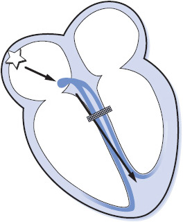
Figure 3-39. Type II second-degree AV block.
• Rate: Can occur at any basic rate.
• Rhythm: Irregular due to blocked beats.
• P waves: Usually regular and precede each QRS. Periodically a P wave is not followed by a QRS complex.
• PR interval: Constant before conducted beats. The PR interval preceding the pause is the same as that following the pause.
• QRS complex: Usually wide because of associated bundle branch block.
• Conduction: Normal through the atria and through the AV node but intermittently blocked in the bundle branch system and fails to reach the ventricles. Conduction through the ventricles is abnormally slow due to associated bundle branch block. Conduction ratios can vary from 2:1 to only occasional blocked beats.
• Example of second-degree AV block type II: Figure 3-40.

Figure 3-40. Second-degree AV block, type II.
Treatment usually includes pacemaker therapy because this type of block is often permanent and progresses to complete block. External pacing can be used for treatment of symptomatic type II block until transvenous pacing can be initiated. Atropine is not recommended because it may result in further slowing of ventricular rate by increasing the number of impulses conducting through the AV node and bombarding the diseased bundles with more impulses than they can handle, resulting in further conduction failure.
High-grade (or advanced) AV block is present when two or more consecutive atrial impulses are blocked when the atrial rate is reasonable (less than 135 beats/min) and conduction fails because of the block itself and not because of interference from an escape pacemaker. High-grade AV block may be type I, occurring in the AV node, or type II, occurring below the AV node. The importance of high-grade block depends on the conduction ratio and the resulting ventricular rate. Because ventricular rates tend to be slow, this arrhythmia is frequently symptomatic and requires treatment.
• Rate: Atrial rate less than 135 beats/min.
• Rhythm: Regular or irregular, depending on conduction pattern.
• P waves: Normal. Present before every conducted QRS, but several P waves may not be followed by QRS complexes.
• PR interval: Constant before conducted beats. May be normal or prolonged.
• QRS complex: Usually normal in type I block and wide in type II block.
• Conduction: Normal through the atria. Two or more consecutive atrial impulses fail to conduct to the ventricles. Ventricular conduction is normal in type I block and abnormally slow in type II block.
• Example of high-grade AV block: Figure 3-41.

Figure 3-41. High-grade AV block.
Treatment of high-grade block is necessary if the patient is symptomatic. Atropine can be given and is generally more effective in type I block. An external pacemaker may be required until transvenous pacing can be initiated, and permanent pacing is often necessary in type II high-grade block.
Third-degree AV block is complete failure of conduction of all atrial impulses to the ventricles (Figure 3-42). In third-degree AV block, there is complete AV dissociation; the atria are usually under the control of the sinus node, although complete block can occur with any atrial arrhythmia; and either a junctional or ventricular pacemaker controls the ventricles. The ventricular rate is usually less than 45 beats/min; a faster rate could indicate an accelerated junctional or ventricular rhythm that interferes with conduction from the atria into the ventricles by causing physiologic refractoriness in the conduction system, thus causing a physiologic failure of conduction that must be differentiated from the abnormal conduction system function of complete AV block. Causes of complete AV block include coronary heart disease, MI, Lev disease, Lenègre disease, cardiac surgery, congenital heart disease, and drugs that slow AV conduction such as digitalis, beta-blockers, and calcium channel blockers.
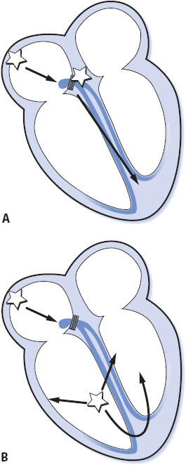
Figure 3-42. Third-degree AV block (complete block). (A) Third-degree AV block with junctional escape pacemaker. (B) Third-degree AV block with ventricular escape pacemaker. (Gilmore SB, Woods SL. Electrocardiography and vectorcardiography. In: Woods SL, Froelicher ES, Motzer SU, eds. Cardiac Nursing. 3rd ed. Philadelphia, PA: JB Lippincott; 1995:291.)
• Rate: Atrial rate is usually normal. Ventricular rate is less than 45 beats/min.
• Rhythm: Regular.
• P waves: Normal but dissociated from QRS complexes.
• PR interval: No consistent PR intervals because there is no relationship between P waves and QRS complexes.
• QRS complex: Normal if ventricles are controlled by a junctional pacemaker. Wide if controlled by a ventricular pacemaker.
• Conduction: Normal through the atria. All impulses are blocked at the AV node or in the bundle branches, so there is no conduction to the ventricles. Conduction through the ventricles is normal if a junctional escape rhythm occurs, and abnormally slow if a ventricular escape rhythm occurs.
• Examples of third-degree AV block: Figure 3-44A,B.
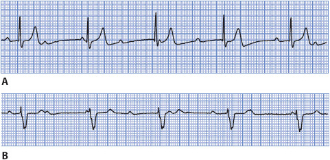
Figure 3-44. (A) Third-degree AV block with a junctional escape pacemaker at a rate of about 36 beats/min. (B) Third-degree AV block with a ventricular escape pacemaker at a rate of about 40 beats/min.
Third-degree AV block can occur without significant symptoms if it occurs gradually and the heart has time to compensate for the slow ventricular rate. If it occurs suddenly in the presence of acute MI, its significance depends on the resulting ventricular rate and the patient’s tolerance. Treatment of complete heart block with symptoms of decreased cardiac output includes external pacing until transvenous pacing can be initiated. Atropine can be given but is not usually effective in restoring conduction.
If the heart fails to generate or conduct impulses to the ventricle, the myocardium can be electrically stimulated using a cardiac pacemaker. A cardiac pacemaker has two components: a pulse generator and a pacing electrode or lead. Temporary cardiac pacing is indicated in any situation in which bradycardia results in symptoms of decreased cerebral perfusion or hemodynamic compromise and does not respond to drug therapy. Signs and symptoms of hemodynamic instability are hypotension, change in mental status, angina, or pulmonary edema. Temporary pacing is also used to terminate some rapid reentrant tachycardias by briefly pacing the heart at a faster rate than the existing rate. When pacing is stopped, the sinus node may resume control of the rhythm if the tachycardia has been terminated. This type of pacing is termed overdrive pacing to distinguish it from pacing for bradycardic conditions.
Temporary cardiac pacing is accomplished by transvenous, epicardial, or external pacing methods. If continued cardiac pacing is required, insertion of permanent pacemakers is done electively. The following section presents an overview of temporary ventricular pacing principles. A more detailed explanation of pacemaker functions is covered in Chapter 18, Advanced ECG Concepts.
Transvenous pacing is usually done by percutaneous puncture of the internal jugular, subclavian, antecubital, or femoral vein and advancing a pacing lead into the apex of the right ventricle so that the tip of the pacing lead contacts the wall of the ventricle (Figure 3-45A). The transvenous pacing lead is attached to an external pulse generator that is kept either on the patient or at the bedside. Transvenous pacing is usually necessary only for a few days until the rhythm returns to normal or a permanent pacemaker is inserted.
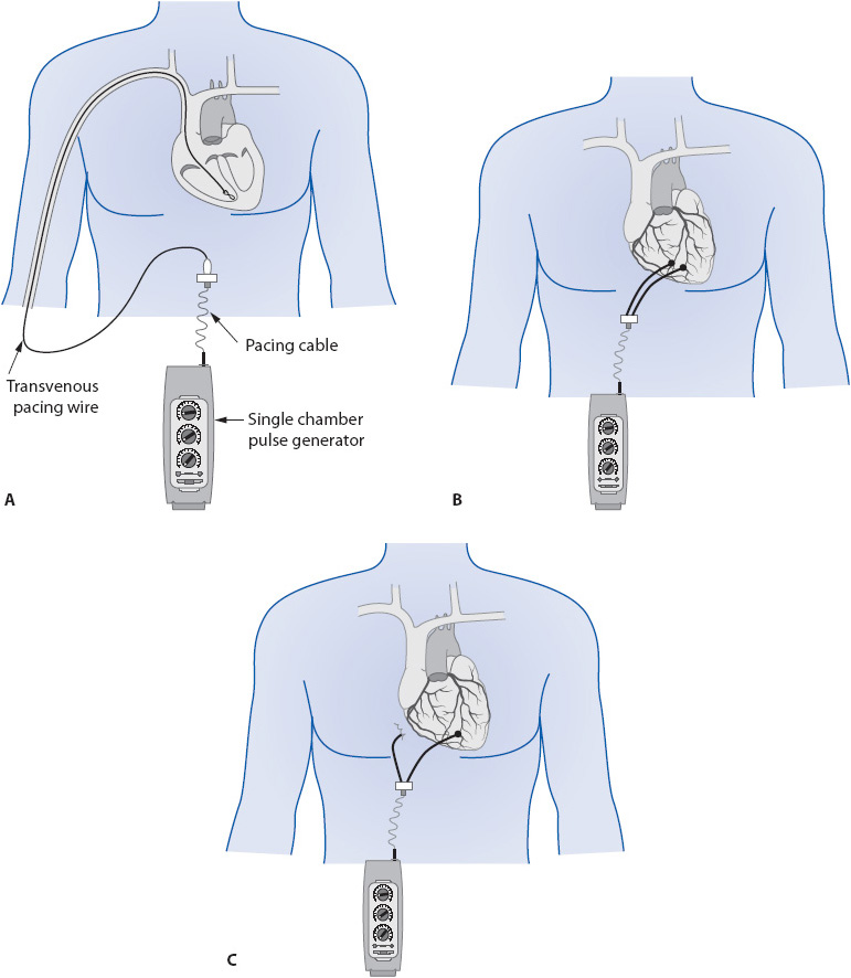
Figure 3-45. Temporary single chamber ventricular pacing. (A) Transvenous pacing with pacing lead in apex of right ventricle. (B) Bipolar epicardial pacing with two epicardial wires on ventricle. (C) Unipolar epicardial pacing with one wire on ventricle and one ground wire in mediastinum.
Epicardial pacing is done through electrodes placed on the atria or ventricles during cardiac surgery. The pacing electrode end of the lead is looped through or loosely sutured to the epicardial surface of the atria or ventricles and the other end is pulled through the chest wall, sutured to the skin, and attached to an external pulse generator (Figure 3-45B,C). A ground wire is often placed subcutaneously in the chest wall and pulled through with the other leads. The number and placement of leads varies with the surgeon.
The basic components of a cardiac pacing system are the pulse generator and the pacing lead. The pulse generator contains the power source (battery) and all of the electronic circuitry that controls pacemaker function. A temporary pulse generator is a box that is kept at the bedside and is usually powered by a regular 9-V battery. It has controls on the front that allow the operator to set pacing rate, strength of the pacing stimulus (output), and sensitivity settings (Figure 3-46).
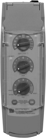
Figure 3-46. Temporary pacemaker pulse generator. (Medtronic, Inc., Minneapolis, MN.)
The pacing lead is an insulated wire used to transmit the electrical current from the pulse generator to the myocardium. A unipolar lead contains a single wire and a bipolar lead contains two wires that are insulated from each other. In a unipolar lead, the electrode is an exposed metal tip at the end of the lead that contacts the myocardium and serves as the negative pole of the pacing circuit. In a bipolar lead, the end of the lead is a metal tip that contacts myocardium and serves as the negative pole, and the positive pole is an exposed metal ring located a few millimeters proximal to the distal tip.
Electrical current flows in a closed-loop circuit between two pieces of metal (poles). For current to flow, there must be conductive material (ie, a lead, muscle, or conductive solution) between the two poles. In the heart, the pacing lead, cardiac muscle, and body tissues serve as conducting material for the flow of electrical current in the pacing system. The pacing circuit consists of the pacemaker pulse generator (the power source), the conducting lead (pacing lead), and the myocardium. The electrical stimulus travels from the pulse generator through the pacing lead to the myocardium, through the myocardium, and back to the pulse generator, thus completing the circuit.
Temporary transvenous pacing is done using a bipolar pacing lead with its tip in the apex of the RV (see Figure 3-45A). Epicardial pacing can be done with either bipolar or unipolar leads. The term bipolar means that both of the poles in the pacing system are in or on the heart (see Figure 3-45B). In a bipolar system, the pulse generator initiates the electrical impulse and delivers it out the negative terminal of the pacemaker to the pacing lead. The impulse travels down the lead to the distal electrode (negative pole or cathode) that is in contact with myocardium. As the impulse reaches the tip, it travels through the myocardium and returns to the positive pole (or anode) of the system, completing the circuit. In a transvenous bipolar system, the positive pole is the proximal ring located a few millimeters proximal to the distal tip. The circuit over which the electrical impulse travels in a bipolar system is small because the two poles are located close together on the lead. This results in a small pacing spike on the ECG as the pacing stimulus travels between the two poles. If the stimulus is strong enough to depolarize the myocardium, the pacing spike is immediately followed by a P wave if the lead is in the atrium, or a wide QRS complex if the lead is in the ventricle.
A unipolar system has only one of the two poles in or on the heart (see Figure 3-45C). In a temporary unipolar epicardial pacing system, a ground lead placed in the subcutaneous tissue in the mediastinum serves as the second pole. Unipolar pacemakers work the same way as bipolar systems, but the circuit over which the impulse travels is larger because of the greater distance between the two poles. This results in a large pacing spike on the ECG as the impulse travels between the two poles.
The two main functions of a pacing system are capture and sensing. Capture means that a pacing stimulus results in depolarization of the chamber being paced (Figure 3-47A). Capture is determined by the strength of the stimulus, which is measured in milliamperes (mA), the amount of time the stimulus is applied to the heart (pulse width), and by contact of the pacing electrode with the myocardium. Capture cannot occur unless the distal tip of the pacing lead is in contact with healthy myocardium that is capable of responding to the stimulus. Pacing in infarcted tissue usually prevents capture. Similarly, if the catheter is floating in the cavity of the ventricle and not in direct contact with myocardium, capture will not occur. In temporary pacing, the output dial on the face of the pulse generator controls stimulus strength, and can be set and changed easily by the operator. Temporary pulse generators usually are capable of delivering a stimulus of 0.1 to 20 mA.
Figure 3-47. (A) Ventricular pacing with 100% capture. Arrows show pacing spikes, each one followed by a wide QRS complex indicating ventricular capture. (B) Rhythm strip of a ventricular pacemaker in the demand mode. There is appropriate sensing of intrinsic QRS complexes and appropriate pacing with ventricular capture when the intrinsic QRS complexes fall below the preset rate of the pacemaker. The seventh beat is fusion between the intrinsic QRS and the paced beat, a normal phenomenon in ventricular pacing.
Sensing means that the pacemaker is able to detect the presence of intrinsic cardiac activity (Figure 3-47B). The sensing circuit controls how sensitive the pacemaker is to intrinsic cardiac depolarizations. Intrinsic activity is measured in millivolts (mV), and the higher the number, the larger the intrinsic signal; for example, a 10-mV QRS complex is larger than a 2-mV QRS. When pacemaker sensitivity needs to be increased to make the pacemaker “see” smaller signals, the sensitivity number must be decreased; for example, a sensitivity of 2 mV is more sensitive than one of 5 mV.
A fence analogy may help to explain sensitivity. Think of sensitivity as a fence standing between the pacemaker and what it wants to see, the ventricle; for example, if there is a 10-ft-high fence (or a 10-mV sensitivity) between the two, the pacemaker may not see what the ventricle is doing. To make the pacemaker able to see, the fence needs to be lowered. Lowering the fence to 2 ft would probably enable the pacemaker to see the ventricle. Changing the sensitivity from 10 to 2 mV is like lowering the fence—the pacemaker becomes more sensitive and is able to “see” intrinsic activity more easily. Thus, to increase the sensitivity of a pacemaker, the millivolt number (fence) must be decreased.
A pacemaker programmed to an asynchronous mode paces at the programmed rate regardless of intrinsic cardiac activity. This can result in competition between the pacemaker and the heart’s own electrical activity. Asynchronous pacing in the ventricle is unsafe because of the potential for pacing stimuli to fall in the vulnerable period of repolarization and cause VF.
The term demand means that the pacemaker paces only when the heart fails to depolarize on its own, that is, the pacemaker fires only “on demand.” In demand mode, the pacemaker’s sensing circuit is capable of sensing intrinsic cardiac activity and inhibiting pacer output when intrinsic activity is present. Sensing takes place between the two poles of the pacemaker. A bipolar system senses over a small area because the poles are close together, and this can result in “undersensing” of intrinsic signals. A unipolar system senses over a large area because the poles are far apart, and this can result in “oversensing.” A unipolar system is more likely to sense myopotentials caused by muscle movement and inappropriately inhibit pacemaker output, potentially resulting in periods of asystole if the patient has no underlying cardiac rhythm. The demand mode should always be used for ventricular pacing to avoid the possibility of VF.
A paced ventricular beat begins with a pacing spike, which indicates that an electrical stimulus was released by the pacemaker (Figure 3-48). If the pacing stimulus is strong enough to depolarize the ventricle, the spike is followed by a wide QRS complex and a T wave that is oriented in the opposite direction of the QRS complex. Figure 3-47A illustrates ventricular pacing with 100% capture.
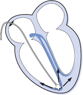
Figure 3-48. Temporary pacing lead in RV apex.
Figure 3-47B is the ECG of a ventricular pacemaker that is functioning correctly in the demand mode. The pacemaker generates an impulse when it senses that the heart rate has decreased below the set pacing rate. Therefore, the pacemaker senses the intrinsic cardiac rhythm of the patient and only generates an impulse when the rate falls below the preset pacing rate. Refer Chapter 18, Advanced ECG Concepts, for more detailed information on single and dual chamber pacing.
Temporary transvenous pacing leads are bipolar and have two tails, one marked “positive” or “proximal” and the other marked “negative” or “distal,” that are connected to the pulse generator. To initiate ventricular pacing using a transvenous lead (see Figure 3-45A):
1. Connect the negative terminal of the pulse generator to the distal end of the pacing lead.
2. Connect the positive terminal of the pulse generator to the proximal end of the pacing lead.
3. Set the rate at 70 to 80 beats/min or as ordered by physician.
4. Set the output at 5 mA, then determine stimulation threshold and set two to three times higher.
5. Set the sensitivity at 2 mV and adjust according to sensitivity threshold.
To initiate bipolar ventricular pacing (two leads on the ventricle; see Figure 3-45B):
1. Connect the negative terminal of the pulse generator to one of the ventricular leads.
2. Connect the positive terminal of the pulse generator to the other ventricular lead.
3. Set the rate at 70 to 80 beats/min or as ordered.
4. Set the output at 5 mA, then determine stimulation threshold and set two to three times higher.
5. Set the sensitivity at 2 mV and adjust according to sensitivity threshold.
To initiate unipolar ventricular pacing (one lead on the ventricle; see Figure 3-45C):
1. Connect the negative terminal of the pulse generator to the ventricular lead.
2. Connect the positive terminal of the pulse generator to the ground lead.
3. Set the rate at 70 to 80 beats/min or as ordered by physician.
4. Set the output at 5 mA, then determine stimulation threshold and set two to three times higher.
5. Set the sensitivity at 2 mV and adjust according to sensitivity threshold. See Chapter 18, Advanced ECG Concepts, for information on how to obtain capture and sensing thresholds.
The emergent nature of many bradycardic rhythms requires immediate temporary pacing. Because transvenous catheter placement is difficult to accomplish quickly, external pacing is the preferred method for rapid, easy initiation of cardiac pacing in emergent situations until a transvenous pacemaker can be inserted. External pacing is done through large-surface adhesive electrodes attached to the anterior and posterior chest wall and connected to an external pacing unit (Figure 3-49). The pacing current passes through skin and chest wall structures to reach the heart; therefore, large energies are required to achieve capture. Sedation and analgesia are usually needed to minimize the discomfort felt by the patient during pacing. Transcutaneous pacing spikes are usually very large, often distorting the QRS complex. The presence of a pulse with every pacing spike confirms ventricular capture.
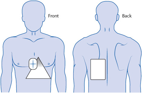
Figure 3-49. External pacemaker with pacing electrode pads on anterior and posterior chest and back.
Defibrillation is the therapeutic delivery of electrical energy to the myocardium to terminate life-threatening ventricular arrhythmias (VF and pulseless VT). The defibrillating shock depolarizes all cells in the heart simultaneously, stopping all electrical activity and allowing the sinus node to resume its function as the normal pacemaker of the heart. Early defibrillation is the only treatment for VF or pulseless VT and should not be delayed for any reason when a defibrillator is available. If a defibrillator is not immediately available, CPR should be started until a defibrillator arrives.
Defibrillation is done externally using two paddles or adhesive pads applied to the skin in the anterolateral position (Figure 3-50A). One paddle or pad is placed under the right clavicle to the right of the sternum and the other paddle or pad is placed to the left of the cardiac apex. If paddles are used, place conductive gel pads on the patient’s skin, then place paddles on the gel pads using 25 lb of pressure to decrease transthoracic impedance and protect the skin from burns. Avoid placing paddles over medication patches or over pacemaker or implantable cardioverter defibrillator (ICD) pulse generators.
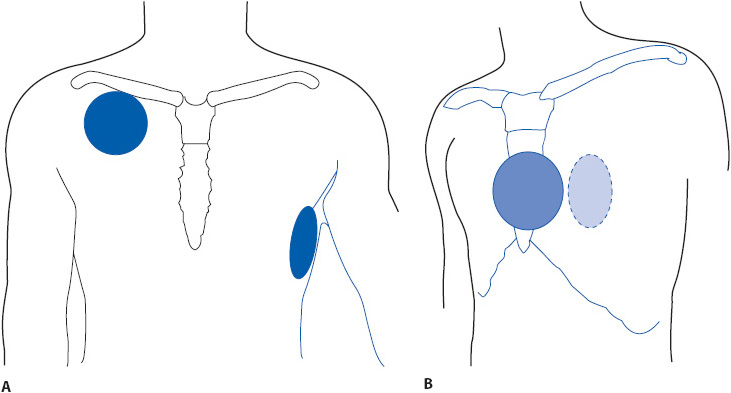
Figure 3-50. Paddle or adhesive pad placement for external defibrillation via (A) anterolateral position and (B) anteroposterior position.
Advanced Cardiac Life Support (ACLS) guidelines recommend an initial energy of 360 J with a monophasic defibrillator and the manufacturer’s recommended energy level for biphasic defibrillators. If the manufacturer’s suggested energy level is not known, a 200-J shock is recommended. Make sure no one is touching the patient, the bed, or anything attached to the patient when the shock is delivered; call “all clear” and visually verify before delivering the shock. Depress the discharge button to release the energy. If using paddles, depress both discharge buttons (one on each paddle) simultaneously. The shock is delivered immediately when buttons are pushed (Figure 3-50A). Immediately resume CPR for 2 minutes before rhythm and pulse check (this may be modified in a monitored situation where ECG and hemodynamic monitoring is available).
An automatic external defibrillator (AED) is a device that incorporates a rhythm-analysis system and a shock advisory system for use by trained laypeople or medical personnel in treating victims of sudden cardiac death. The American Heart Association recommends that AEDs should be available in selected areas where large gatherings of people occur and where immediate access to emergency care may be limited, such as on airplanes, in airports, sports stadiums, health and fitness facilities, and so on. It is well known that early defibrillation is the key to survival in patients experiencing VF or pulseless VT. Any delay in the delivery of the first shock, including delays related to waiting for the arrival of trained medical personnel and equipment, can decrease the chance of survival. The availability of an AED in public areas can prevent unnecessary delays in treatment and improve survival in victims of sudden cardiac death.
Operation of an AED is quite simple and can be performed by laypeople. Instructions for use are printed on the machines and voice commands also guide the operator in using the AED. Adhesive pads are placed in the standard defibrillation position on the chest (see Figure 3-50A), the machine is turned on, and the rhythm analysis system analyzes the patient’s rhythm. If the rhythm analysis system detects a shockable rhythm, such as VF or rapid VT, a voice advises the operator to shock the patient. Delivery of the shock is a simple maneuver that only involves pushing a button. The operator is advised to “stand clear” prior to delivering the shock. After a shock is delivered, the system prompts the operator to resume CPR. After 2 minutes of CPR it prompts the operator to stop CPR while it reanalyzes the rhythm.
Cardioversion is the delivery of electrical energy that is synchronized to the QRS complex so that the energy is delivered during ventricular depolarization in order to avoid the T wave and the vulnerable period of ventricular repolarization. The delivery of electrical energy near the T wave can lead to ventricular fibrillation. Synchronized cardioversion is used to terminate both supraventricular and ventricular tachycardias and is usually an elective procedure, although it should be performed urgently if the patient is hemodynamically unstable. Cardioversion can be performed via anterolateral electrode placement (see Figure 3-50A) or via anteroposterior (AP) electrode placement (see Figure 3-50B). Anteroposterior placement is preferred because less energy is required and the success rate is higher when energy travels through the short axis of the chest. Either paddles or hands-free adhesive pads can be used.
Sedation is required for cardioversion since the patient is usually awake and alert and able to feel the pain caused by the procedure. Sedation can be accomplished with drugs like midazolam (Versed), methohexital (Brevital Sodium), propofol, or others at the discretion of the physician; or an anesthesiologist may be used to administer deep sedation. Because sedation is used, an emergency cart, emergency drugs (lidocaine, epinephrine, amiodarone, atropine), sedation-reversal agent, O2-delivery equipment, and suction equipment should be immediately available; and an O2 saturation monitor and noninvasive blood pressure (BP) monitoring should be done continuously during the procedure and until the patient is completely awake and recovered.
Initial energy level for cardioversion is typically 50 to 100 J and varies with different arrhythmias. If the first shock is unsuccessful, energy level is increased for subsequent shocks. The machine must be synchronized to the QRS complex for cardioversion. Most machines put a bright dot or similar marker on the QRS complex when in the “synch” mode (Figure 3-51B). The machine will not discharge its energy until it sees the synch marker. Make sure to visually verify that the synch marker is actually on the QRS complex and not on a tall T wave. When delivering energy during cardioversion, push and hold the discharge button until the energy is delivered; the synchronized machine will not discharge until it sees a QRS complex. When the energy is released, the machine automatically returns to the asynchronous mode, so if subsequent shocks are needed the machine must be resynchronized.
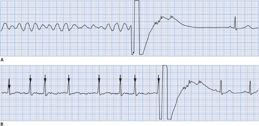
Figure 3-51. (A) Defibrillation of VF to sinus rhythm. (B) Cardioversion of atrial fibrillation to sinus rhythm. Note the synchronization mark on the QRS.
Brenyo, AJ, Aktas, MK. Non-pharmacologic management of atrial fibrillation. Am J Cardiol. 2011;108:317-325.
Calkins, H. Supraventricular tachycardia: atrioventricular nodal reentry and Wolff-Parkinson-White syndrome. In Fuster V, Walsh RA, Harrington RA. eds. Hurst’s The Heart. 13th ed. New York: McGraw Hill. 2011: 987-1005.
Jacobson, C. Arrhythmias and conduction disturbances. In Woods SL, Froelicher ES, Motzer SU, Bridges EJ. eds. Cardiac Nursing. 6th ed. Philadelphia: Lippincott Williams & Wilkins. 2010: 333-387.
Jacobson, C. Gerity, D. Pacemakers and implantable difibrillators. In Woods SL, Froelicher ES, Motzer SU, Bridges EJ. eds. Cardiac Nursing. 6th ed. Philadelphia: Lippincott Williams & Wilkins. 2010: 655-704.
Jacobson C, Marzlin K, Webner C. Cardiovascular Nursing Practice: A Comprehensive Resource Manual and Study Guide for Clinical Nurses. Burien, WA: Cardiovascular Nursing Education Associates. 2007.
Kenny, T. The Nuts and Bolts of Cardiac Pacing. Malden, MA: Blackwell Futura. 2005.
Kerber, RE. Indications and techniques of electrical defibrillation and cardioversion. In Fuster V, Walsh RA, Harrington RA. eds. Hurst’s The Heart. 13th ed. New York: McGraw Hill. 2011: 1088-1093.
Link, MS, Atkins, DL, Passman, RS, et al. Electrical therapies: automated external defibrillators, defibrillation, cardioversion, and pacing: 2010 American Heart Association Guidelines for Cardiopulmonary Resuscitation and Emergency Cardiovascular Care. Circulation. 2010:122(suppl 3), Part 6, S706–S719.
Olgin, J, Zipes, DP. Specific arrhythmias: diagnosis and treatment. In Bonow RO, Mann DL, Zipes DP, Libby P. eds. Braunwald’s Heart Disease—A Textbook of Cardiovascular Medicine. 9th ed. Philadelphia: Elsevier. 2011: 771-824.
Prystowsky, EN, Padanilam, BJ, Waldo, AL. Atrial fibrillation, atrial flutter, and atrial tachycardia. In Fuster V, Walsh RA, Harrington RA. eds. Hurst’s The Heart. 13th ed. New York: McGraw Hill. 2011: 963-986.
Pugazhendhi, V, Ellenbogen, KA. Bradyarrhythmias and pacemakers. In Fuster V, Walsh RA, Harrington RA. eds. Hurst’s The Heart. 13th ed. New York: McGraw Hill. 2011: 1025-1057.
Rho, RW, Page, RL. Ventricular arrhythmias. In Fuster V, Walsh RA, Harrington RA. eds. Hurst’s The Heart. 13th ed. New York: McGraw Hill. 2011: 1006-1024.
Advanced Cardiovascular Life Support Provider Manual. Dallas, TX: American Heart Association. 2011.
Blomstrom-Lundqvist C, Scheinman MM, Aliot EM, et al. ACC/AHA/ESC Guidelines for the Management of Patients with Supraventricular Arrhythmias - Executive Summary. A Report of the American College of Cardiology/American Heart Association Task Force on Practice Guidelines and the European Society of Cardiology Committee for Practice Guidelines (Writing Committee to Develop Guidelines for the Management of Patients With Supraventricular Arrhythmias). Circulation. 2003:108;1871-1909.
Bourgault, A. (2008). AACN Practice Alert: Dysrhythmia Monitoring. Aliso Viejo, CA: American Association of Critical Care Nurses. http://www.aacn.org
Drew, BJ, Califf, RM, Funk, M, et al. Practice standards for electrocardiographic monitoring in hospital settings. Circulation. 2004:110;2721-2746.
Furie, KL, Goldstein, LB, Albers, GW, et al. Oral antithrombotic agents for the prevention of stroke in nonvalvular atrial fibrillation: a science advisory for healthcare professionals from the American Heart Association/American Stroke Association. Stroke, 2012:43;3442-3453.
Fuster, V, Ryden, LE, Cannom, DS, et al. 2011 ACCF/AHA/HRS focused updates incorporated into the ACC/AHA/ESC 2006 guidelines for the management of patients with atrial fibrillation: a report of the American College of Cardiology Foundation/American Heart Association Task Force on Practice Guidelines. Circulation, 2011:123;e269–e367.
Jacobson C. Bedside cardiac monitoring. In Burns S, ed. AACN Protocols for Practice: Noninvasive Monitoring. 2nd ed. Boston: Jones and Bartlett; 2006.
Wann, LS, Curtis, AB, January, CT, et al. 2011 ACCF/AHA/HRS focused update on the management of patients with atrial fibrillation (updating the 2006 guideline): a report of the American College of Cardiology Foundation/American Heart Association Task Force on Practice Guidelines. Circulation. 2011(a):123; 104-123.
Wann, LS, Curtis, AB, January, CT, et al. 2011 ACCF/AHA/HRS focused update on the management of patients with atrial fibrillation (update on dabigatran): a report of the American College of Cardiology Foundation/American Heart Association Task Force on Practice Guidelines. Circulation. 2011(b):123;1144-1150.
Zipes, D, Camm, A, Borggrefe, M, et al. ACC/AHA/ESC 2006 guidelines for management of patients with ventricular arrhythmias and the prevention of sudden cardiac death: a report of the American College of Cardiology/American Heart Association Task Force and the European Society of Cardiology Committee for Practice Guidelines Circulation, 2006:114;e385-e484.