A flash opens up a whole new world of photographic possibilities. You are no longer dependent on just the ambient light but can now add illumination exactly where and when you want it. Called Speedlights since they were introduced back in the 1960s, the Nikon flashes are compact, powerful, and pretty easy to use right out of the box.
The Nikon Speedlights (in fact, all flashes) are amazing pieces of technology. They produce a bright, consistent flash of light over and over again and yet are small enough to fit in your pocket. They don’t need to be plugged into a power source but instead run on regular batteries that can be purchased anywhere.
The four basic components to a flash are the flash tube, a transformer, the capacitor, and a power source. When the flash is turned on the transformer takes the low voltage energy from the power source (AA batteries in the case of most Speedlights), turns it into high voltage energy, and fills the capacitor. When you trigger the Speedlight, the energy in the capacitor is released and fires the flash tube to create a quick, bright, burst of light. When the capacitor is filled again, the flash is ready to fire once more. The recycle time depends on the freshness of the batteries, and how much of the capacitor was drained on the previous flash. The more power that the flash needs, the longer it takes to recharge the capacitor, the longer you have to wait between flashes, and the quicker you will drain the batteries.
Once the capacitor has fully charged, the flash lets you know it is ready to fire by illuminating the ready lamp on the back of the unit. If the flash is mounted on the camera a flash ready indicator through the viewfinder. It is possible to fire the flash before it has a full charge but you don’t get the full illumination power if you do.
The true marvel is that you can choose to manually or automatically adjust the amount of energy from the capacitor that is used, thereby changing the power of the flash and the amount of illumination. Put the flash in TTL (Through The Lens) mode to change flash power automatically based on what the camera sees, or use Manual mode to control the output yourself. When the output of the flash is adjusted, the intensity of the flash doesn’t actually change, but instead the length of the flash either increases or decreases depending on the power setting. The longer the duration of the flash, the more light is produced.
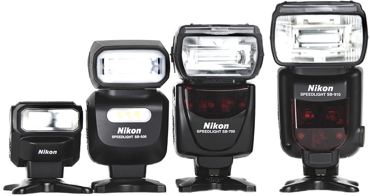
The current Nikon Speedlights range from the simple SB-300 all the way to the feature-laden SB-910 ( Figure 5.1 ). Each of the current flashes works with the full line of Nikon DSLRs and many of the Nikon COOLPIX cameras. The way I look at it, the SB-300 is a low-end flash for those who need a just a little extra light right on the camera. This flash does not have any of the wireless controls of the more advanced flashes. The lineup offers a couple of mid-level flashes for those wanting more power, flexibility, and the Advanced Wireless Lighting (AWL) functions. These flashes, the SB-500 and SB-700, cost a little more but allow for greater creative control over your images. Then there is the top-of-the-line flash, the SB-910. This is the unit with all the bells and whistles, the cream of the crop, and the most advanced choice in the Nikon lineup. It also comes with the heftiest price tag and retails for more than twice as much as the midrange units.
The SB-300 AF Speedlight is the simplest of the Nikon flashes. Although it can help to add some extra light to your images, it is really quite limited in function, especially compared to the SB-500. The SB-300 has a power switch and a ready lamp on the back, and you can angle the flash head up and down. Limited in its ability, this Speedlight cannot be used off-camera as part of an Advanced Wireless Lighting setup. Because the flash head does not rotate, you can bounce the flash in one direction only. This is the least powerful of the Nikon Speedlights and runs off two AAA batteries.
The SB-300 cannot be used as a Commander or a remote for off-camera work.
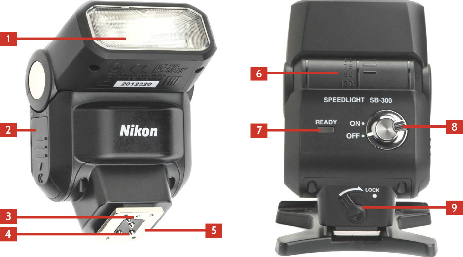
Figure 5.2 shows the SB-300’s features.
1. Flash head : The flash head contains the flash tube.
2. Battery chamber cover : The SB-300 takes two AAA batteries. Sliding the cover toward the base of the flash opens the battery compartment.
3. Mounting lock pin : There is a small pin that when extended locks the flash into the hot shoe or the flash stand. The mounting foot lock (9 ) controls the mounting lock pin.
4. Hot shoe contacts : These are contacts that pass the information between the flash and camera.
5. Mouting foot : This is the metal foot that connects the flash to the hot shoe on the camera or the flash stand.
6. Flash head tilt scale : This scale shows the vertical position of the flash head to 120 degrees.
7. Ready light : When the flash is ready to fire, this light comes on.
8. On/Off : This switch turns the flash on and off.
9. Mounting foot lock : This lever locks and unlocks the flash when it is attached to the hot shoe of a camera or on the flash stand.
Released in late 2014, the SB-500 is the newest addition to the Speedlight family, and it has a feature that is unique among all the current Speedlights. Not only does the SB-500 have a regular flash, it also has a built-in, 100-lux LED video light that you can set to three power levels. This is the first, and currently only, Speedlight to have this capability.
The SB-500 can be used as a remote in the AWL mode using the A or B group only using channel 3 and as a Commander only when attached to the Nikon D810 or the Nikon D750. The SB-500 takes two AA batteries and can go through them pretty quickly when using the LED video light.
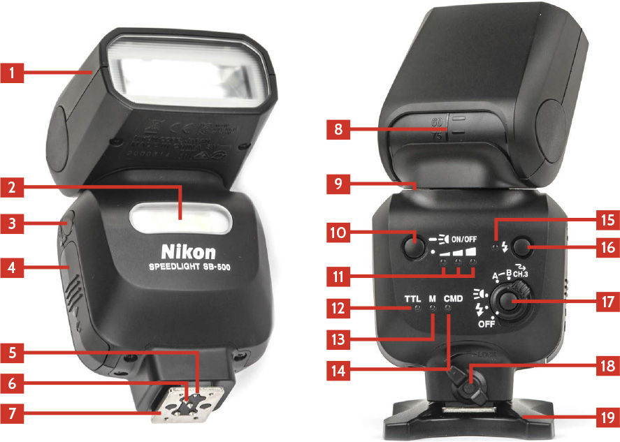
Figure 5.3 shows the SB-500’s features.
1. Flash head : The flash head contains the flash tube.
2. LED light : The LED light is housed in the body of the flash and is not adjustable like the flash head.
3. Wireless triggering sensor : The Advanced Wireless Lighting capabilities of the Creative Lighting System use line-of-sight triggering, and this is the sensor on the flash that reads the light from the Commander unit when the SB-500 is in Remote mode. You need to be careful that this sensor is visible to the Commander for the system to work properly.
4. Battery chamber cover : The SB-500 takes two AA batteries. Sliding the cover toward the base of the flash opens the battery compartment.
5. Mounting lock pin : There is a small pin that when extended locks the flash into the hot shoe or the flash stand. The mounting foot lock (18 ) controls the mounting lock pin.
6. Hot shoe contacts : These are contacts that pass the information between the flash and camera.
7. Mounting foot : This is the metal foot that connects the flash to the hot shoe on the camera or the flash stand.
8. Flash head tilt scale : This scale shows the vertical position of the flash head to 90 degrees.
9. Flash head rotate scale : This scale shows the horizontal position of the flash head. It can rotate 180 degrees left or right.
10. LED power setting button : Tapping this button cycles through the power settings of the LED. Press and hold the button to turn the LED on and off.
11. LED power setting indicator : These lights show the current power setting of the LED lamp.
12. TTL indicator : When lit, the flash is in TTL mode.
13. Manual mode indicator : When the flash is in Manual mode, this light is lit. The flash can be placed in Manual mode only by selecting Manual in the Optional Flash menu on the camera.
14. Commander mode indicator : The SB-500 Speedlight can be used as a Commander when mounted on a Nikon D750 or Nikon D810. When in this mode, the Commander indicator light is illuminated.
15. Ready light : When the flash is ready to fire, this lamp is red.
16. Test fire button : When the ready light is glowing red, pressing this button fires the flash.
17. On/Off/LED/Remote : This switch turns the flash on and sets the mode. You can set it to either regular flash, LED, Group A, or Group B.
18. Mounting foot lock : This lever locks and unlocks the flash when it is attached to the hot shoe of a camera or on the flash stand.
19. Flash stand : The SB-500 comes with a hard-plastic flash stand that allows the flash to be placed off-camera. The stand has a tripod socket on the bottom allowing the stand to be placed on a tripod or light stand.
The SB-500 comes with a soft case and a Speedlight stand but does not have a diffusion dome or any color-correcting gels. The SB-500 does not have a sync terminal or the ability to use an external power pack. This flash is also noticeably more compact than the SB-700 and SB-910.
The SB-500 works as a TTL flash when attached to the camera. All you have to do is mount it on the camera hot shoe and turn it on. The flash has no real controls, but instead the camera controls the flash mode and power. The only controls on the flash allow you to change the mode from flash to LED light and then to set the flash into the Remote mode.
The Nikon SB-500 can be used as a Commander to control the off-camera remote flashes but only when used with the D810 and D750 camera models. The SB-500 needs to be mounted on the camera hot shoe; then, in the camera menu system, choose Commander mode under the Optional flash setting. You can then set up to two groups in one of four channels. When the SB-500 is in Commander mode, the Commander mode indicator (14 ) is illuminated.
The SB-500 can be used as a remote flash in either the A or B group using channel 3. Setting the flash as a remote unit is easy; all you have to do is rotate the on/off/LED/remote switch (17 ) to either the A or the B.
The SB-700 was released in 2010 as an update to the SB-600. This Speedlight can act as either a Commander or a remote. When used as a Commander, it can trigger remote Speedlights in two groups, A and B, and when used as a remote can be part of the A, B, or C group. This flash has a convenient slide switch that enables you to change the pattern of the light easily from Standard for general photography to Center-Weighted for portraits or to Even for group shots or lighting interiors. The SB-700 has two hard-plastic color-correcting filters that the flash can read and in turn send the proper white balance information to the camera. The SB-700 also has a built-in bounce card that the SB-600 lacked and comes with a diffusion dome and a stand.
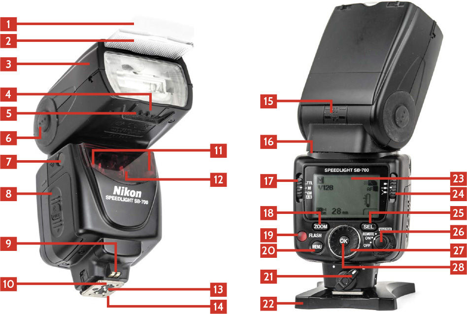
Figure 5.4 shows the SB-700’s features.
1. Built-in bounce card : This built-in white plastic bounce card is meant to bounce a little light when the flash head is not pointed directly at the subject.
2. Built-in wide flash diffuser : When this diffuser is pulled out and placed over the flash head, the light from the flash is spread out to cover the area covered by a 14mm focal length. The zoom on the flash is automatically set to 14mm when it is in use.
3. Flash head : The flash head contains the flash tube and the mechanism that zooms the flash head. The SB-700 automatically sensors the focal length of the lens attached and adjusts the zoom to match.
4. Filter detectors : When the hard-plastic filter is attached to the flash head, the flash can read the filter and set the white balance automatically.
5. Diffusion dome detector : The SB-700 can tell when the supplied diffusion dome is attached and automatically adjusts the zoom.
6. Flash head tilting/rotating lock release button : Pressing this button allows you to adjust the tilt and rotation of the flash head. The flash head can rotate left or right 180 degrees and can tilt up 90 degrees.
7. Sensor for wireless triggering : The Advanced Wireless Lighting capabilities of the Creative Lighting System use line-of-sight triggering, and this is the sensor on the flash that reads the light from the Commander when in Remote mode. You need to be careful that this sensor is visible to the Commander for the system to work properly.
8. Battery chamber cover . The SB-700 takes four AA batteries. Sliding the cover toward the base of the flash opens the battery compartment.
9. AF-Assist contacts : These contacts are used to communicate between the flash and camera when the AF-Assist Illuminator (12 ) is needed.
10. Mounting lock pin : There is a small pin that when extended locks the flash into the hot shoe or the flash stand. The mounting foot lock (28 ) controls the mounting lock pin.
11. Remote ready light : When the SB-700 is in Remote mode, there are two lights that will flash in the front of the flash, letting you know it is ready to fire. The front placement makes it easier to see when the flash is placed off-camera.
12. AF-Assist Illuminator : In low-light situations and when the attached DSLR is set to Single-Subject Auto-Focus, the built-in LED projects a red light on your subject to help the camera achieve focus.
13. Hot shoe contacts : These are contacts that pass the information between the flash and camera.
14. Mounting foot : This is the metal foot that connects the flash to the hot shoe on the camera or the flash stand.
15. Flash head tilt scale : This scale shows the vertical position of the flash head from –7 degrees to 90 degrees.
16. Flash head rotate scale : This scale shows the horizontal position of the flash head. It can rotate 180 degrees left or right.
17. Mode switch : This switch controls which mode the flash is in. Just slide it between TTL, Manual, and GN.
18. Zoom button : You can change the zoom of the flash by pressing this button. It cycles through the zoom range of the flash.
19. Ready light/test button : This light comes on when the flash is ready to fire. Pressing the button will trigger the flash.
20. Menu button : Press the menu button to open the custom setting menu. You can then use the selector dial (27 ) to choose an item and the OK button (28 ) to open that setting menu.
21. Mounting foot lock : This lever locks and unlocks the flash when it is attached to the hot shoe of a camera or on the flash stand.
22. Flash stand : The SB-700 comes with a hard-plastic flash stand that allows the flash to be placed off-camera. The stand has a tripod socket on the bottom allowing the stand to be placed on a tripod or light stand.
23. LCD screen : The LCD screen shows the current setting for the flash.
24. Flash pattern selector switch : The SB-700 has three different illumination patterns that are set here by sliding the switch up or down. The Standard setting is the basic pattern used for most situations. The Center-Weighted pattern puts more of the flash in the center of the frame and less on the edges. The light falls off quicker than with the Standard setting. The final pattern is the Even setting where the light does not fall off at the edges as much as the Standard or Center-Weighted patterns.
25. SEL button : This button allows you to change a selected setting on the flash depending on the mode. Press the SEL button to highlight the setting and then use the selector dial (27 ) and to adjust the setting and the OK button (28 ) to confirm it. On the LCD screen there will be an icon above the SEL button depicting what it is currently set to adjust.
26. On/Off/Remote/Master switch : This is the power switch that turns the flash on and allows you to easily set the mode from regular flash to Remote or Commander mode. You will need to press the button in the middle of the switch to Remote or Commander mode.
27. Selector dial : You can rotate the selector dial to change settings on the flash depending on the current mode.
28. OK button : The OK button has two functions. The first is when pressed once to confirm a setting. The second is when you hold the button down for a second, which then opens the custom functions menu.
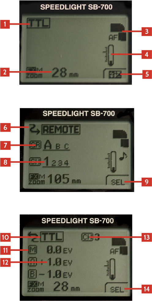
Figure 5.5 shows the information on the SB-700’s LCD screen.
1. Flash mode : This shows the current setting of the flash. Pressing the Mode button cycles through the modes available on the flash.
2. Zoom setting : This shows the current zoom setting of the flash. It will change depending on the lens attached, the focal length, and any diffusers attached.
3. Flash graphic : This shows that the AF-Assist Illuminator (12 ) is working, the angle of the flash head, and the pattern of the light.
4. Temperature gauge : This shows how hot the flash is getting. If the flash gets too hot, it will shut off automatically.
5. Label : This shows the function of the button right below the screen. In normal use, it is set to adjust the flash compensation.
6. Wireless mode icon : This arrow icon shows that the flash is in Advanced Wireless mode.
7. Remote group : This shows what group the remote is currently set to.
8. Remote channel : This shows the current channel the flash is set for.
9. Label : This shows the function of the button right below the screen when in Remote mode; here it is set to act as the SEL button.
10. Master flash mode : This shows what mode all the remote flashes will use. The mode is changed by the slider switch on the back left of the flash. The mode is set for all the groups at once.
11. Group icon : The A and B icons stand for the two groups that the SB-700 can trigger. The M is for the Master flash on the camera.
12. Group power adjustment : The power adjustment for each group is shown here, either as a fraction when in Manual mode or as + or – stops of light.
13. Channel : This is the channel that the Commander is set to. The remotes need to be on the same channel to work.
14. Label : This shows the function of the button right below the screen in Commander mode where it is set to act as the SEL button.
The SB-700 can act as a Commander (or Master) flash controlling an unlimited number of remote flash units in two groups, A or B, using one of four channels. To use the SB-700 in Commander mode, just follow these steps:
1. Put the flash on the camera and lock it in place using the mounting foot lock.
2. Turn the power switch to MASTER.
3. Set the mode switch to TTL, Manual, or GN.
4. Press the SEL button to cycle through the channels and groups.
5. When on a group, use the dial to adjust the power for that selected group and then press the SEL button to go to the next one.
6. When the channel is highlighted, use the dial to pick between the four available channels.
Remember that all the remote flashes need to be using the same channel as the Commander and in groups A and B.
The SB-700 can be used as a remote for off-camera flash. You can set the SB-700 to the A, B, or C group and use any of the four channels. To use the SB-700 in Remote mode, follow these steps:
1. Turn the power switch to REMOTE.
2. Press the SEL button to switch between the Group mode (GR) and the Channel (CH).
3. When in the Group mode, use the dial to select the A, B, or C group.
4. When in the Channel setting, use the dial to select between channels 1, 2, 3, and 4.
Remember that all the remote flashes need to be using the same channel as the Commander. You also need to make sure that if you are using group C, you are using a Commander that supports group C, such as the SU-800, SB-800, SB-900, or SB-910.
The SB-910 is the current top-of-the-line Speedlight. It is the biggest, most powerful Nikon flash available. The SB-910 is a small upgrade to the discontinued SB-900, with a few small cosmetic changes including illuminated Function, Mode, and Menu buttons and a reworked thermal cut-off circuit.
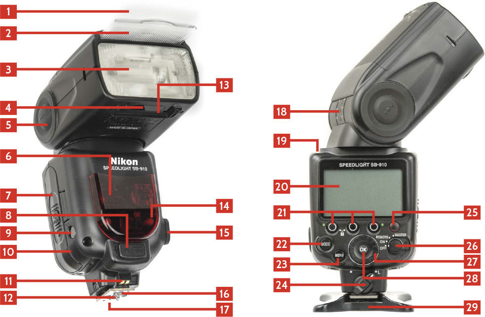
Figure 5.6 shows the SB-910’s features.
1. Built-in bounce card : This built-in white plastic bounce card is meant to bounce a little light when the flash head is not pointed directly at the subject.
2. Built-in wide flash diffuser : When this diffuser is pulled out and placed over the flash head, the light from the flash is spread out to cover the area covered by a 17mm focal length. The zoom on the flash is automatically set to 17mm when it is in use.
3. Flash head : The flash head contains the flash tube and the mechanism that zooms the flash head. The SB-910 automatically sensors the focal length of the lens attached and adjusts the zoom to match.
4. Filter detectors : When the hard-plastic filter is attached to the flash head, the flash can read the filter and set the white balance automatically
5. Flash head tilting/rotating lock release button : Pressing this button allows you to adjust the tilt and rotation of the flash head. The flash head can rotate left or right 180 degrees and can tilt from 90 degrees up to –7 degrees down.
6. AF-Assist Illuminator : In low-light situations and when the attached DSLR is set to Single-Subject Auto-Focus, the built-in LED projects a red light on your subject to help the camera achieve focus.
7. Battery chamber cover : The SB-910 takes four AA batteries. Sliding the cover toward the base of the flash opens the battery compartment.
8. External battery terminal : This port is where the external battery pack (SD-9) plugs into the flash. You need to remove the plastic plug on the flash before you can plug the battery in.
9. Sensor for wireless triggering : The Advanced Wireless Lighting capabilities of the Creative Lighting System use line-of-sight triggering, and this is the sensor on the flash that reads the light from the Commander when in Remote mode. You need to be careful that this sensor is visible to the Commander for the system to work properly.
10. Sensor for non-TTL auto flash : This sensor allows the flash to read the light being bounced off the subject, allowing the flash to meter the light instead of relying on the TTL information from the camera.
11. AF-Assist contacts : These contacts are used to communicate between the flash and camera when the AF-Assist Illuminator (6 ) is needed.
12. Hot shoe contacts : These are contacts that pass the information between the flash and camera.
13. Diffusion dome detector : The SB-910 can tell when the supplied diffusion dome is attached and automatically adjusts the zoom.
14. Remote ready light : When the SB-910 is in Remote mode, there are two lights that will flash in the front of the flash, letting you know it is ready to fire. The front placement makes it easier to see when the flash is placed off-camera.
15. Sync terminal : This port allows you to use a sync cable to fire your flashes.
16. Mounting lock pin : There is a small pin that when extended locks the flash into the hot shoe or the flash stand. The mounting foot lock (28) controls the mounting lock pin.
17. Mounting foot : This is the metal foot that connects the flash to the hot shoe on the camera or the flash stand.
18. Flash head tilt scale : This scale shows the vertical position of the flash head from –7 degrees to 90 degrees.
19. Flash head rotate scale : This scale shows the horizontal position of the flash head. It can rotate 180 degrees left or right.
20. LCD : The LCD screen on the back of the SB-910 shows the currently selected flash functions and gives the function buttons context.
21. Function buttons : The SB-910 has three buttons located under the LCD that have different functions depending on the flash mode. Their function is annotated above each button on the LCD screen. From left to right as you look at the back of the flash, these are function buttons 1, 2, and 3.
22. Mode button : The Mode button controls which mode the flash is in. Press the button to cycle through the flash modes.
23. Zoom button : You can change the zoom of the flash by pressing this button. It cycles through the zoom range of the flash.
24. Mounting foot lock : This lever locks and unlocks the flash when it is attached to the hot shoe of a camera or on the flash stand.
25. Ready light/test button : This light comes on when the flash is ready to fire. Pressing the button will trigger the flash.
26. On/Off/Remote/Master switch : This is the power switch that turns the flash on and allows you to easily set the mode from regular flash to Remote or Commander mode. You will need to press the button in the middle of the switch to Remote or Commander mode.
27. Selector dial : You can rotate the selector dial to change settings on the flash depending on the current mode.
28. OK button : The OK button has two functions. The first is when pressed once to confirm a setting. The second is when you hold the button down for a second, which then opens the custom functions menu.
29. Flash stand : The SB-910 comes with a hard-plastic flash stand that allows the flash to be placed off-camera. The stand has a tripod socket on the bottom allowing the stand to be placed on a tripod or light stand.
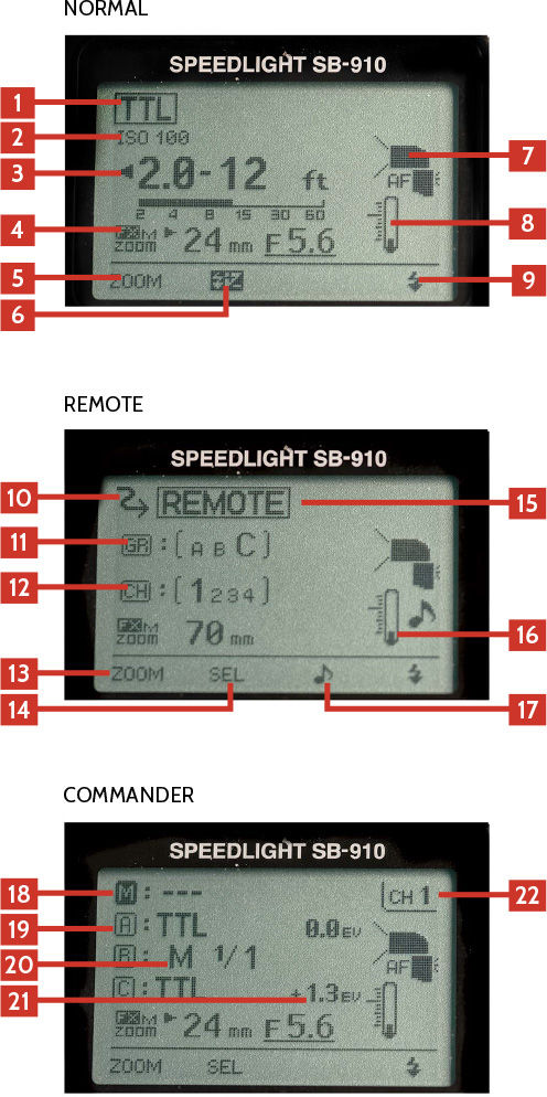
Figure 5.7 shows the information on the SB-910’s LCD screen.
1. Flash mode : This shows the current setting of the flash. Pressing the Mode button cycles through the modes available on the flash.
2. Camera ISO : This shows the current ISO of the camera that the flash is attached to.
3. Effective flash output range : This shows the effective range of the flash with the current settings.
4. Zoom setting : This shows the current zoom setting of the flash. It will change depending on the lens attached, the focal length, and whether any diffusers are attached.
5. Label 1 : This shows the function of the function button right below the screen. In normal use, it is set to the Zoom button.
6. Label 2 : This shows the function of the function button right below the screen. In normal use, it is set to flash compensation button.
7. Flash graphic : This shows at the AF-Assist Illuminator is working, the angle of the flash head and the pattern of the light.
8. Temperature gauge : This shows how hot the flash is getting. If the flash gets too hot, it will shut off automatically.
9. Label 4 : This shows the function of the Test button right below the screen. It can either test the flash or fire the modeling light function.
10. Wireless Mode icon : This arrow icon shows that the flash is in Advanced Wireless mode.
11. Remote group : This shows what group the remote is currently set to.
12. Remote channel : This shows the current channel the flash is set for.
13. Label 1 : This shows the function of the function button right below the screen. In Remote use, it is set to the Zoom button.
14. Label 2 : This shows the function of the function button right below the screen. In Remote mode, it is set to SEL or the select function.
15. Remote Mode icon : When in Remote mode, the flash shows the word “REMOTE” across the back.
16. Sound icon : The SB-910 can be set to beep when ready to fire in Remote mode. This icon shows that status of sound setting.
17. Label 3 : This shows the function of the function button right below the screen; in Remote mode, it is set to sound.
18. Master flash mode : This shows what mode the SB-910 attached to the camera will use if it is going to add light to the scene. In this example the --- means that the flash will not be adding any light.
19. Group icon : The A, B, and C icons stand for the three groups that the SB-910 can trigger.
20. Group flash mode : The mode for each group can be different. Here is where you can easily see and adjust the flash modes.
21. Group power adjustment : The power adjustment for each group is shown here, either as a fraction when in Manual mode or as + or – stops of light.
22. Channel : The channel that the Commander is set to. The remotes need to be on the same channel to work.
The SB-910 Speedlight can be used as a Commander unit to control an unlimited number of remote flash units in three groups using one of four channels. To use the SB-910 as a Commander, just follow these steps:
1. Mount the flash on the camera and turn the mounting foot lock to the right to lock the flash on the camera.
2. Turn the flash to Master mode using the power switch.
3. Use the function button 1 to cycle through the A, B, and C groups along with the Master flash.
4. With the selected group highlighted, press the Mode button to select the mode for that group from the following choices:
--- means that the group is turned off and will not fire.
TTL sets the group to TTL mode, and the camera will control the power of the flash based on the light that the camera reads in the scene.
M is Manual mode, where you control the power of the flash as a fraction.
A is Aperture mode.
5. Use function button 2 to select the flash output.
6. Adjust the flash output of the selected group by using the Select dial and then press the OK button.
7. Press function button 2 to select the channel. Pressing the button cycles through the four available channels.
Remember that all the remote flashes need to be using the same channel as the Commander to work.
The SB-910 can be used as a remote for off-camera flash. The SB-910 can be set to the A, B, or C group and use any of the four channels. To use the SB-900 in Remote mode, follow these steps:
1. Turn the power switch to REMOTE.
2. Press function button 2 to switch between the Group mode (GR) and the channel (CH).
3. When in the Group mode, use the Select dial to select the A, B, or C group.
4. When in the Channel setting, use the Select dial to select between channels 1, 2, 3, and 4.
Remember that all the remote flashes need to be using the same channel as the Commander. You also need to make sure that if you are using group C, you are using a Commander that supports group C, such as the SU-800, SB-800, SB-900, or SB-910.
There are two specialized Nikon Speedlights, the SB-R200 remote unit and the SU-800 Commander unit. The SB-200 is a small unit meant to be attached to the front of the lens for close-up work and cannot be mounted on the camera hot shoe or used without a separate flash in Commander mode or the SU-800 as a trigger. The SU-800 Commander is a dedicated unit used to trigger off-camera Speedlights in Advanced Wireless Lighting usage.
The SB-R200 is a specialized Speedlight designed mainly for close-up work. This Speedlight cannot be used alone but instead is used as a remote unit triggered by either a Speedlight in Commander mode, an SU-800 Commander unit, or a built-in flash set to Commander mode. The SB-R200 doesn’t have a standard mounting foot and cannot be mounted on a camera hot shoe. The SB-R200 can be used in the A, B, or C group in one of four channels.
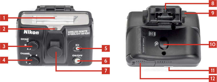
Figure 5.8 shows the SB-R200’s features.
1. Flash head : The flash head of the SB-R200 is basically the whole body of the flash. The flash head does not zoom.
2. Target light : This light helps you aim the SB-R200. It can be turned on remotely using the SU-800 or the SB-R200 target light switch (4 ).
3. Group dial : This determines the group to which the SB-R200 is set. Just rotate the dial to change between A, B, and C.
4. Channel dial : This sets the channel that the flash uses to communicate between the Commander and the remote. Turn the dial to pick the channel you want to use, 1, 2, 3, or 4.
5. Target light switch : Pressing this turns the target light (2 ) on or off.
6. On/Off button : Turns the flash on and off.
7. TTL cord terminal : The SB-R200 can be used with older cameras that do not have Creative Lighting System capability by using the SU-800 and the optional TTL SC-30 cord. The cord from the SU-800 plugs in here.
8. Mounting foot : The mounting foot of the SB-R200 is made to attach to the SX-1 attachment ring. Once the flash is mounted, slide the lock into place.
9. Foot adjustment release button : The SB-R200 attaches to the SX-1 attachment ring and not to the camera hot shoe. The position of the flash can be adjusted by pressing in these buttons and sliding the flash around.
10. Sensor for wireless control : This is the sensor that the Commander flash needs to see in order to trigger this unit. The sensor is on the bottom because this is the part that faces the camera when the flash is attached to the front of the lens using the SX-1 attachment ring.
11. Ready light : This light illuminates when the flash is ready to fire.
12. Battery chamber : The SB-R200 takes one CR123A (3V) lithium battery. Slide the battery chamber cover to the outside of the flash to open.
13. Stand (not shown) : The SB-R200 comes with a special stand that allows the flash to be used without the SX-1 attachment ring.
The SB-R200 is always in Remote mode and cannot be used any other way. The controls for the flash are on the top, with the power button on the right and two dials on the left. Just set the group with the top dial and the channel with the bottom dial, and the flash is ready to go. The sensor that the Commander flash needs to “see” is located under the flash, perfectly positioned to activate the flash when the SB-R200 is used as part of the Nikon close-up kit, which is covered in Chapter 6 .
The Nikon SU-800 is a compact unit that uses infrared signals to trigger the remote flashes. The SU-800 does not add any illumination to the scene because it has no flash tube. The advantage to the SU-800 is that it costs a lot less than the SB-910 and has the same ability to act as a Commander for unlimited flashes in groups A, B, and C.
You can reset the SU-800 Commander to the factory defaults by pressing and holding the on/off and mode buttons simultaneously. The LCD panel will blink three times.
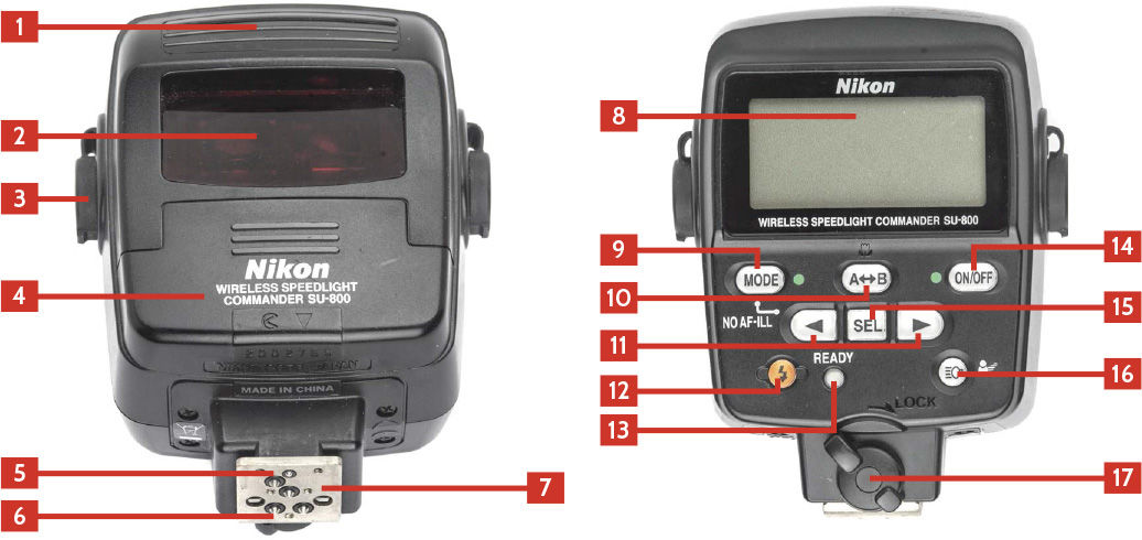
Figure 5.9 shows the SU-800’s features.
1. Commander transmit window : The infrared transmitter is behind this window.
2. AF-Assist Illuminator : In low-light situations and when the attached DSLR is set to Single-Subject Auto-Focus, the built-in LED projects a red light on your subject to help the camera achieve focus.
3. TTL cord terminal : You can connect the SU-800 to the SB-R200 using an optional SC-20 TTL cord while using a camera that doesn’t support Creative Lighting System.
4. Battery chamber : The SU-800 takes one CR123A (3V) lithium battery. Slide the battery chamber cover down toward the mounting foot to open.
5. Mounting lock pin : When the mounting foot lock lever (17) is turned, this pin locks the SU-800 to the camera so that the unit.
6. Hot shoe contacts : These are contacts that pass the information between the flash and camera.
7. Mounting foot : This is the metal foot that connects the flash to the hot shoe on the camera or the flash stand.
8. LCD panel : This shows the settings used on the SU-800.
9. Mode button : When a group is selected, pressing this cycles through the modes that group can be set to.
10. A–B select button : When used in Close-Up mode, this button is used to set the units in Groups A and B to fire.
11. Left and right arrow buttons : This allows you to navigate the SU-800 menus.
12. Test fire button : Pressing this fires any remote flashes.
13. Ready light : This comes on when the unit is ready to fire.
14. On/Off button : Pressing this button turns the SU-800 on and off.
15. Select button : This allows you to set the current settings.
16. Target light button : Press this to turn the target light on the SB-R200 on or off when used with the SB-R200.
17. Mounting foot lock lever : Turning this lever engages the mounting lock pin (5 ) securing the SU-800 to the camera.
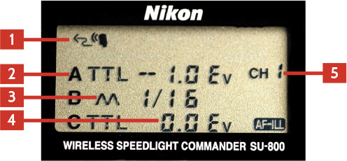
Figure 5.10 shows the information on the SU-800’s LCD screen.
1. Remote mode icon : This shows that the SU-800 is in Advanced Wireless mode.
2. Group icons : You can control the A, B, or C group from the Commander.
3. Mode : This shows which mode the group is set to. Each group can be set to a different mode.
4. Group power adjustment : The power adjustment for each group is shown here, either as a fraction when in Manual mode or as + or – stops of light.
5. Channel : The channel that the Commander is set to. The remotes need to be on the same channel to work.
The SU-800 Commander works in the Commander mode only. Follow these quick steps to get started:
1. Mount the SU-800 on the camera and engage the locking lever.
2. Turn the SU-800 on by pressing the on/off button.
3. Press the SEL button to navigate to Group A, B, and C settings.
4. Press the Mode button to change the mode for the selected group.
5. Press the arrow buttons to adjust the power of the group.
6. Press the SEL to get to the channel and then use the arrow keys to select the channel you want to use.
Make sure the remote flashes are set to the same channel, and you are good to go.
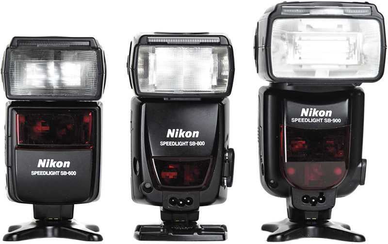
Although the older flashes discussed in this section ( Figure 5.11 ) have been discontinued by Nikon, many are still available as used gear and work great. In fact, I continue to use a few of these quite frequently. They all work with the Nikon Creative Lighting System, and just because they are older doesn’t make them useless.
Note
The only older flash that I don’t recommend is the discontinued SB-400. You can’t use it as part of the Advanced Wireless Lighting setup nor does the flash head allow for bouncing the light. The SB-400 was designed simply as a more powerful alternative to the built-in flash, and better choices are now on the market.
The SB-600 was released in 2004 and discontinued in 2010 and was the second flash to be part of the Creative Lighting System but was also compatible with the older digital and film cameras. The SB-600 was designed to be used on the camera as a dedicated flash unit or as a remote flash unit triggered by another flash in Commander mode. The SB-600 cannot be used as a controller to trigger remote flashes.
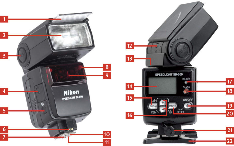
Figure 5.12 shows the SB-600’s features.
1. Built-in wide flash diffuser : When pulled out and placed over the flash head, this diffuser spreads out the light from the flash to cover an area sufficient for a 14mm focal length. The zoom on the flash is automatically set to 14mm when it is in use.
2. Flash head : The flash head contains the flash tube and the mechanism that zooms the flash head. The SB-600 automatically sensors the focal length of the lens attached and adjusts the zoom to match.
3. Flash head tilting/rotating lock release button : Pressing this button allows you to adjust the tilt and rotation of the flash head. The flash head can rotate left or right 180 degrees and can tilt from 90 degrees up to –7 degrees down.
4. Battery chamber cover : The SB-600 takes four AA batteries. Sliding the cover toward the base of the flash opens the battery compartment.
5. Sensor for wireless triggering : The Advanced Wireless Lighting capabilities of the Creative Lighting System use line-of-sight triggering, and this is the sensor on the flash that reads the light from the Commander when in Remote mode. You need to be careful that this sensor is visible to the light from the Commander for the system to work properly.
6. AF-Assist contacts : These contacts are used to communicate between the flash and camera when the AF-Assist Illuminator (11 ) is needed.
7. Hot shoe contacts : These are contacts that pass the information between the flash and camera.
8. Remote ready light : When the SB-600 is in Remote mode, there are two lights that will flash in the front of the flash, letting you know it is ready to fire. The front placement makes it easier to see when the flash is placed off-camera.
9. AF-Assist Illuminator : In low-light situations and when the attached DSLR is set to Single-Subject Auto-Focus, the built-in LED projects a red light on your subject to help the camera achieve focus.
10. Mounting lock pin : There is a small pin that when extended locks the flash into the hot shoe or the flash stand. The mounting foot lock (21) controls the mounting lock pin.
11. Mounting foot : This is the metal foot that connects the flash to the hot shoe on the camera or the flash stand.
12. Flash head tilt scale : This scale shows the vertical position of the flash head 90 degrees.
13. Flash head rotate scale : This scale shows the horizontal position of the flash head. It can rotate 180 degrees left to 90 degrees right.
14. LCD : The LCD screen on the back of the flash shows the current settings.
15. Zoom button : You can change the zoom of the flash by pressing this button. It cycles through the zoom range of the flash. When pressed with the – button (14) for two seconds, the custom menu opens.
16. + and – buttons : These are used to navigate and adjust the settings on the flash.
17. Ready light : This light comes on when the flash is ready to fire.
18. Test button : Pressing this button will trigger the flash.
19. On/Off switch : This is the power switch that turns the flash on and off.
20. Mode button : The Mode button controls which mode the flash is in. Press the button to cycle through the flash modes.
21. Mounting foot lock : This lever locks and unlocks the flash when it is attached to the hot shoe of a camera or on the flash stand.
22. Flash stand : The SB-600 comes with a hard-plastic flash stand that allows the flash to be placed off-camera. The stand has a tripod socket on the bottom allowing the stand to be placed on a tripod or light stand.
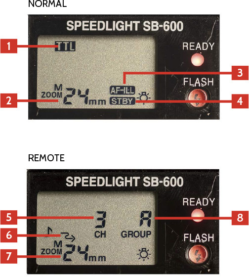
Figure 5.13 shows the information on the SB-600’s LCD screen.
1. Flash mode : The text in this position will show the mode the flash is set to. Pressing the Mode button cycles through the flash modes.
2. Zoom : This shows the current zoom of the flash head.
3. AF-Assist Illuminator : The flash can use the AF-assist illuminator when this is lit.
4. Standby : This shows that the flash is being used in Standby mode, which conserves power by powering down after 40 seconds.
5. Remote channel : This shows the current channel being used by the SB-600 in remote mode.
6. Remote flash icon : This mode shows that the camera is in the Advanced Wireless mode.
7. Zoom position : This shows the zoom position of the flash head in remote mode.
8. Remote group : This is the group to which the remote is set.
The SB-600 can be used as a remote in the A, B, or C group in one of four channels. To use the SB-600 as a remote flash, just follow these steps:
1. Turn on the flash by pressing the on/off button.
2. Press and hold the Zoom button and the – button at the same time.
3. Press the + button until you see the Advanced Wireless Lighting symbol; it looks like a squiggly arrow pointing to the right.
4. Press the Mode button to change from off to on.
5. Press the on/off button.
6. Press the Mode button until the number above the CH starts to blink and then press the + or – button to change the channel.
7. Press the Mode button until the letter above the GROUP starts to blink and then use the + or – button to select the group.
The SB-600 is now ready to be used as a remote flash; just make sure that the Commander flash is using the same channel.
Considered by many to be the best flash that Nikon has ever produced, the Nikon SB-800 is still sought after by many photographers for its power and versatility, as well as its ability to be both a remote or Commander in the Creative Lighting System.
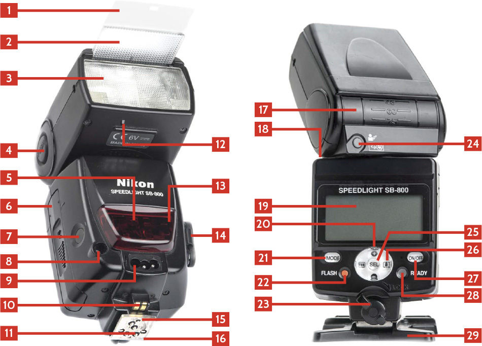
Figure 5.14 shows the SB-800’s features.
1. Built-in bounce card : This built-in white plastic bounce card is meant to bounce a little light when the flash head is not pointed directly at the subject.
2. Built-in wide flash diffuser : When pulled out and placed over the flash head, this diffuser spreads the light from to cover an area sufficient for a 14mm focal length. The zoom on the flash is automatically set to 14mm when it is in use.
3. Flash head : The flash head contains the flash tube and the mechanism that zooms the flash head. The SB-800 automatically sensors the focal length of the lens attached and adjusts the zoom to match.
4. Flash head tilting/rotating lock release button : Pressing this button allows you to adjust the tilt and rotation of the flash head. The flash head can rotate left or right 180 degrees and can tilt from 90 degrees up to –7 degrees down.
5. AF-Assist Illuminator : In low-light situations and when the attached DSLR is set to Single-Subject Auto-Focus, the built-in LED projects a red light on your subject to help the camera achieve focus.
6. Battery chamber cover : The SB-910 takes four AA batteries. Sliding the cover toward the base of the flash opens the battery compartment.
7. Sensor for wireless triggering : The Advanced Wireless Lighting capabilities of the Creative Lighting System use line-of-sight triggering, and this is the sensor on the flash that reads the light from the Commander when in Remote mode. You need to be careful that this sensor is visible to the light from the Commander for the system to work properly.
8. Sensor for non-TTL auto flash : This sensor allows the flash to read the light being bounced off the subject, allowing the flash to meter the light instead of relying on the TTL information from the camera.
9. External battery terminal : This port is where the external battery pack (SD-9) plugs into the flash. You need to remove the plastic plug on the flash before you can plug the battery in.
10. AF-Assist contacts : These contacts are used to communicate between the flash and camera when the AF-Assist Illuminator (5 ) is needed.
11. Hot shoe contacts : These are contacts that pass the information between the flash and camera.
12. Diffusion dome detector : The SB-800 can tell when the supplied diffusion dome is attached and automatically adjusts the zoom to the widest 14mm.
13. Remote ready light : When the SB-910 is in Remote mode, there are two lights that will flash in the front of the flash, letting you know it is ready to fire. The front placement makes it easier to see when the flash is placed off-camera.
14. Sync terminal : This port allows you to use a sync cable to fire your flashes.
15. Mounting lock pin : There is a small pin that when extended locks the flash into the hot shoe or the flash stand. The mounting foot lock (28) controls the mounting lock pin.
16. Mounting foot : This is the metal foot that connects the flash to the hot shoe on the camera or the flash stand.
17. Flash head tilt scale : This scale shows the vertical position of the flash head from –7 degrees to 90 degrees.
18. Flash head rotate scale : This scale shows the horizontal position of the flash head. It can rotate 180 degrees in left or right.
19. LCD : Screen showing the current state of the flash.
20. + and – buttons : These are used to control the function of the flash depending on the mode.
21. Mode button : The Mode button controls which mode the flash is in. Press the button to cycle through the flash modes.
22. Test button : The ready light (28) comes on when the flash is ready to fire. Pressing the button will trigger the flash.
23. Mounting foot lock : This lever locks and unlocks the flash when it is attached to the hot shoe of a camera or on the flash stand.
24. Modeling light button : Pressing this button fires the flash continuously in a low-power mode so you can check to see how the final image will look. This can really eat up the battery power, and it is easier just to take a test shot to see how everything looks. If the SB-800 is in Remote mode, the flash will not fire while this button is pressed.
25. SEL button : The SEL button sets the currently selected item.
26. Zoom buttons : These two buttons change the flash head zoom position from 24mm to 105mm.
27. On/Off : This is the power switch that turns the flash on and off. It also closes the custom menu.
28. Ready light : This light comes on when the flash is ready to fire.
29. Flash stand : The SB-800 comes with a hard-plastic flash stand that allows the flash to be placed off-camera. The stand has a tripod socket on the bottom allowing the stand to be placed on a tripod or light stand.
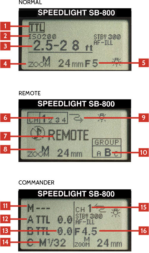
Figure 5.15 shows the information on the SB-800’s LCD screen.
1. Flash mode : This shows the current setting of the flash. Pressing the Mode button cycles through the modes available on the flash.
2. Camera ISO : This shows the current ISO of the camera to which the flash is attached.
3. Effective flash output range : This shows the effective range of the flash with the current settings.
4. Zoom setting : This shows the current zoom setting of the flash. It will change depending on the lens attached, the focal length, and any diffusers attached.
5. Aperture : The current aperture setting of the camera.
6. Remote channel : This shows the current channel the flash is set for.
7. Remote mode icon : When in Remote mode, the flash shows “REMOTE” across the back.
8. Zoom setting : This is the current zoom setting of the remote flash.
9. Wireless Mode icon : This arrow icon shows that the flash is in Advanced Wireless mode.
10. Remote group : This shows what group the remote is currently set to.
11. Master flash mode : This shows what mode the SB-800 attached to the camera will use if it is going to add light to the scene. In this example, the --- means that the flash will not be adding any light.
12. Group icon : The A, B, and C icons stand for the three groups that the SB-800 can trigger.
13. Group power adjustment : The power adjustment for each group is shown here, either as a fraction when in Manual mode or as + or – stops of light.
14. Group flash mode : The mode for each group can be different. Here you can easily see and adjust the flash modes.
15. Channel : This is the channel that the Commander is set to. The remotes need to be on the same channel to work.
16. Aperture : This shows the aperture set by the camera.
The SB-800 was the first Speedlight to incorporate the Nikon Creative Lighting System and was the first to have the Advanced Wireless Lighting capability. When it was designed, the settings for turning the flash to Commander mode (and Remote mode) were not as easily accessible as the subsequent Speedlights. To set the SB-800 as a Commander (or Master) flash, you need to do the following:
1. Press and hold the SEL (Select) button until the menu system opens.
2. Use the rocker switch to select the Master/Remote setting.
3. Press the SEL button, and the word “OFF” is highlighted at right.
4. Use the rocker switch to select Master and then press the SEL button.
5. Press the on/off button once, and the flash is now set to Master mode.
In this mode, you can now set the mode and power for the SB-800 that is on the camera and each of the three groups. Each of the groups can have a different mode and power setting, but remember that all the flashes in that group will have the same settings.
The SB-800 can be set as a remote flash in any of the three groups. To set the flash as a remote, just follow these steps:
1. Press and hold the SEL (Select) button until the menu system opens.
2. Use the rocker switch to select the Master/Remote setting.
3. Press the SEL button, and the word “OFF” is highlighted at right.
4. Use the rocker switch to select Remote and then press the SEL button.
5. Press the on/off button once, and the flash is now set to Remote mode.
Once the flash is set to Remote mode, the only settings you need to concern yourself with are the group and the channel. The SB-800 can be set to the A, B, or C group and use any of the four channels, so just make sure that the Commander you are using to trigger the off-camera flashes is set to the same channel and can trigger all three groups if you use C.
The SB-900 was the update to the SB-800, but it had an issue with overheating and was soon replaced with the SB-910. The SB-900 and the SB-910 are basically the same flash, except the SB-910 resolved the overheating issue. That is not to say that the SB-900 is a bad flash; I have one and use it all the time. You do have to pay more attention when using it a lot in quick succession. This flash was considered the top-of-the-line flash when it came out and can do everything that the SB-910 can do.
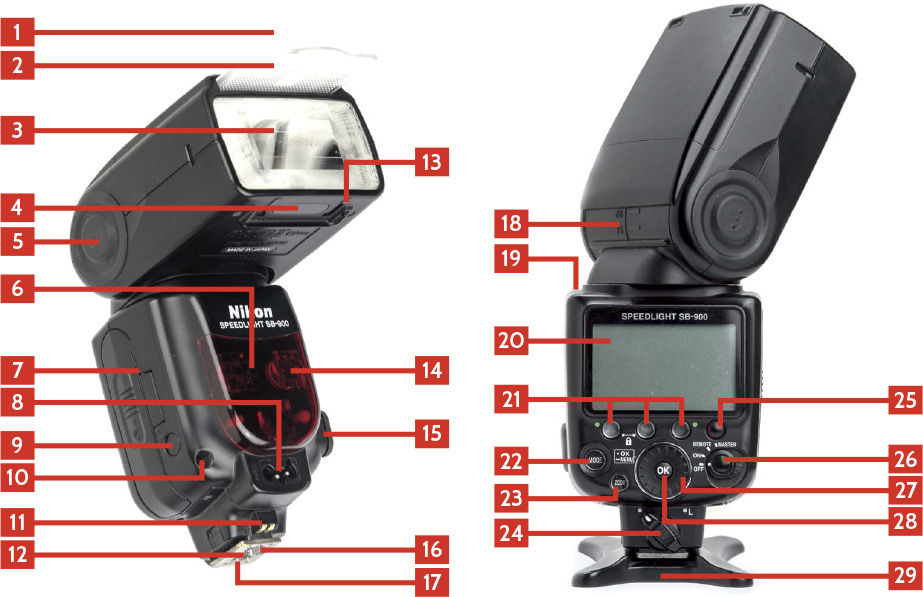
Figure 5.16 shows the SB-900’s features.
1. Built-in bounce card : This built-in white plastic bounce card is meant to bounce a little light when the flash head is not pointed directly at the subject.
2. Built-in wide flash diffuser : When pulled out and placed over the flash head, this diffuser spreads the light from the flash to cover an area sufficient for a 17mm focal length. The zoom on the flash is automatically set to 17mm when it is in use.
3. Flash head : The flash head contains the flash tube and the mechanism that zooms the flash head. The SB-900 automatically sensors the focal length of the lens attached and adjusts the zoom to match.
4. Filter detectors : When the plastic filter holder and gel filter is attached to the flash head, the flash can read the filter and set the white balance automatically.
5. Flash head tilting/rotating lock release button : Pressing this button allows you to adjust the tilt and rotation of the flash head. The flash head can rotate left or right 180 degrees and can tilt from 90 degrees up to –7 degrees down.
6. Remote ready light : When the SB-900 is in Remote mode, there are two lights that will flash in the front of the flash, letting you know it is ready to fire. The front placement makes it easier to see when the flash is placed off-camera.
7. Battery chamber cover : The SB-900 takes four AA batteries. Sliding the cover toward the base of the flash opens the battery compartment.
8. External battery terminal : This port is where the external battery pack (SD-9) plugs into the flash. You need to remove the plastic plug on the flash before you can plug the battery in.
9. Sensor for wireless triggering : The Advanced Wireless Lighting capabilities of the Creative Lighting System use line-of-sight triggering, and this is the sensor on the flash that reads the light from the Commander when in Remote mode. You need to be careful that this sensor is visible to the light from the Commander for the system to work properly.
10. Sensor for non-TTL auto flash : This sensor allows the flash to read the light being bounced off the subject, allowing the flash to meter the light instead of relying on the TTL information from the camera.
11. AF-Assist contacts : These contacts are used to communicate between the flash and camera when the AF-Assist Illuminator (17 ) is needed.
12. Hot shoe contacts : These are contacts that pass the information between the flash and camera.
13. Diffusion dome detector : The SB-900 can tell when the supplied diffusion dome is attached and automatically adjusts the zoom.
14. AF-Assist Illuminator : In low-light situations and when the attached DSLR is set to Single-Subject Auto-Focus, the built-in LED projects a red light on your subject to help the camera achieve focus.
15. Sync terminal : This port allows you to use a sync cable to fire your flashes.
16. Mounting lock pin : There is a small pin that when extended locks the flash into the hot shoe or the flash stand. The mounting foot lock (22) controls the mounting lock pin.
17. Mounting foot : This is the metal foot that connects the flash to the hot shoe on the camera or the flash stand.
18. Flash head tilt scale : This scale shows the vertical position of the flash head from –7 degrees to 90 degrees.
19. Flash head rotate scale : This scale shows the horizontal position of the flash head. It can rotate 180 degrees left or right.
20. LCD : The LCD screen on the back of the SB-900 shows the currently selected flash functions and gives the function buttons context.
21. Function buttons : The SB-900 has three function buttons located under the LCD. The buttons have different functions depending on the flash mode. Their function is annotated above each button on the LCD screen. From left to right as you look at the back of the flash, these are function buttons 1, 2, and 3.
22. Mode button : The Mode button controls which mode the flash is in. Press the button to cycle through the flash modes.
23. Zoom button : You can change the zoom of the flash by pressing this button. It cycles through the zoom range of the flash.
24. Mounting foot lock : This lever locks and unlocks the flash when it is attached to the hot shoe of a camera or on the flash stand.
25. Ready light/test button : This light comes on when the flash is ready to fire. Pressing the button will trigger the flash.
26. On/Off/Remote/master switch : This is the power switch that turns the flash on and allows you to easily set the mode from regular flash to Remote or Commander mode. You will need to press the button in the middle of the switch to Remote or Commander mode.
27. Selector dial : You can rotate the selector dial to change settings on the flash depending on the current mode.
28. OK button : The OK button has two functions. Press it once to confirm a setting, or hold the button down for a second to open the Custom Functions menu.
29. Flash stand : The SB-900 comes with a hard-plastic flash stand that allows the flash to be placed off-camera. The stand has a tripod socket on the bottom, allowing the stand to be placed on a tripod or light stand.
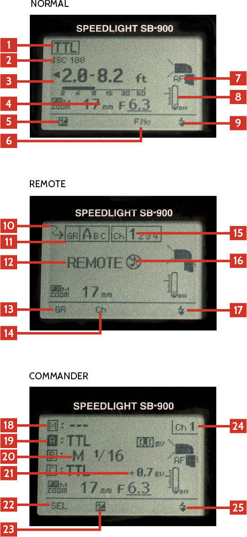
Figure 5.17 shows the information on the SB-900’s LCD screen.
1. Flash mode : This shows the current setting of the flash. Pressing the Mode button cycles through the modes available on the flash.
2. Camera ISO : This shows the current ISO of the camera to which the flash is attached.
3. Effective flash output range : This shows the effective range of the flash with the current settings.
4. Zoom setting : This shows the current zoom setting of the flash. It will change depending on the lens attached, the focal length, and any diffusers attached.
5. Label 1 : This shows the function of the function button right below the screen; in normal use it is set to the exposure compensation.
6. Label 3 : This shows the function of the function button right below the screen; in normal use, it is set to Adjusting the FNo.
7. Flash graphic : This shows that the AF-Assist Illuminator is working, the angle of the flash head, and the pattern of the light.
8. Temperature gauge : This shows how hot the flash is getting. If the flash gets too hot, it will shut off automatically.
9. Label 4 : This shows the function of the Test button right below the screen. It can either test the flash or fire the modeling light function.
10. Wireless Mode icon : This arrow icon shows that the flash is in Advanced Wireless mode.
11. Remote group : This shows which group the remote is currently set to.
12. Remote Mode icon : When in Remote mode, the flash shows the word “REMOTE” across the back.
13. Remote channel : This shows the current channel the flash is set for.
14. Label 1 : This shows the function of the function button right below the screen; in Remote mode, it is set to the Group button.
15. Label 2 : This shows the function of the function button right below the screen; in Remote mode, it is set to Channel or select function.
16. Remote channel : This shows the current channel the flash is set for.
17. Sound icon : The SB-910 can be set to beep when ready to fire in Remote mode. This icon shows that status of sound setting; in this case, it is off.
18. Label 4 : This shows the function of the function button right below the screen; in Remote mode, it is set to sound.
19. Master flash mode : This shows what mode the SB-900 attached to the camera will use if it is going to add light to the scene. In this example, the --- means that the flash will not be adding any light.
20. Group icon : The A, B, and C icons stand for the three groups that the SB-910 can trigger.
21. Group flash mode : The mode for each group can be different. Here you can easily see and adjust the flash modes.
22. Group power adjustment : The power adjustment for each group is shown here, either as a fraction when in Manual mode or as + or – stops of light.
23. Label 1 : This shows the function of the function button right below the screen; in Commander mode, it is set to the SEL button.
24. Label 2 : This shows the function of the function button right below the screen; in Commander mode, it is set to change the selected group power.
25. Channel : This is the channel that the Commander is set to. The remotes need to be on the same channel to work.
26. Label 4 : This shows the function of the Test button right below the screen. It can either test the flash or fire the modeling light function.
The SB-900 Speedlight can be used as a Commander unit to control an unlimited number of remote flash units in three groups using one of four channels. To use the SB-900 as a Commander, just follow these steps:
1. Mount the flash on the camera, and turn the Mounting Foot Lock to the right to lock the flash on the camera.
2. Turn the flash to Master mode using the power switch.
3. Use function button 1 to cycle through the A, B, and C groups along with the Master flash.
4. With the selected group highlighted, press the Mode button to select the mode for that group from the following choices:
--- means that the group is turned off and will not fire.
TTL sets the group to TTL mode and the camera will control the power of the flash based on the light that the camera reads in the scene.
M is Manual mode where you control the power of the flash as a fraction.
A is Aperture mode.
5. Use function button 2 to select the flash output.
6. Adjust the flash output of the selected group by using the Select dial and then press the OK button.
7. Press function button 2 to select the channel. Pressing the button cycles through the four available channels.
Remember that all the remote flashes need to be using the same channel as the Commander to work.
The SB-900 can be used as a remote for off-camera flash. The SB-900 can be set to the A, B, or C group and use any of the four channels. To use the SB-900 in remote mode, follow these steps:
1. Turn the power switch to REMOTE.
2. Press function button 2 to switch between the Group mode (GR) and the Channel (CH).
3. When in the Group mode, use the Select dial to select the A, B, or C group.
4. When in the Channel setting, use the Select dial to select among channels 1, 2, 3, and 4.
Remember that all the remote flashes need to be using the same channel as the Commander. You also need to make sure that if you are using group C, you are using a Commander that supports group C, such as the SU-800, SB-800, SB-900, or SB-910.
The great thing about the Nikon Speedlights is that they all work together. You can grow your collection without having to spend top dollar for every additional light. For example, I use SB-600s and SB-700s as remote units controlled by an SB-910. This allows me to use multiple Speedlights without having to purchase multiple SB-910s.
Most of the cameras in the Nikon DSLR lineup can act as Commanders using the built-in pop-up flash. This allows you to start with one Speedlight and use it both on and off the camera.