Chapter 4. Blocking In
With preparation finished and concept art and reference at the ready, we can move on to modeling. Modeling is the process of creating a 3D object that is made up of individual points connected to form faces, which in turn make up more complex shapes. There are many ways to create models in Blender, from modifying primitives, like a simple cube or sphere, to building the surface of a mesh face by face or drawing smooth curves that Blender can convert into objects composed of vertices and faces.
Modeling can be a long process, and to save time, it helps to know where you are going with a particular modeling task. Still, you can’t model an object all at once; you have to start somewhere, and that’s where blocking in comes in. Blocking in is the process of adding simple placeholders for the objects you want to create so that you can better plan how they fit together, consider their individual constructions, and spot problems before they become major issues. Once a scene has been blocked in, you can move on to refining, replacing, or adding to each part to create a final model. For example, in the Jungle Temple scene, simple elements like cubes are used as placeholders for key elements; for other projects, we create simple base meshes for sculpting that act as a foundation for developing the final form of our sculpted models.
Basic Modeling Terms
Before we dive in, here are some definitions of Blender’s basic modeling concepts that I’ll use throughout this chapter. Table 4-1 lists them in hierarchical order: Vertices make up edges, which make up faces, and so on.
Edit Mode
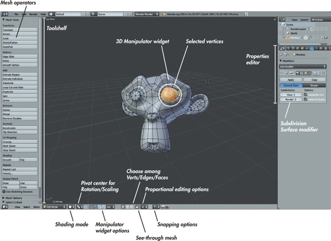
Edit mode (shown in Figure 4-1) is where the modeling magic happens. With a mesh object selected, you can enter Edit mode by pressing TAB or by clicking the mode drop-down menu in the 3D Viewport header and selecting Edit mode. Once in Edit mode, your selected object is editable (if it is in fact editable—empty objects and lamps, for example, are not). When an object is editable, you can select and manipulate parts as well as create new parts.
Description | |
vertex (plural vertices); also known as a vert | A single point in 3D space with a specific location. Vertices are connected to construct meshes. |
edge | A line connecting two vertices. |
face (or polygon) | Three or more vertices connected by edges and filled with a flat surface. A polygon formed of three vertices is called a tri (short for triangle). A polygon formed of four vertices is called a quad (short for quadrangle). Polygons with more than four vertices are called n-gons. |
normal | The direction in which a face or vertex points. Imagine a flagpole pointing straight out from the surface of an object. The direction it points is the face normal. Vertices and edges can also have normals when they are part of a surface. |
mesh | A collection of vertices, faces, and edges that are all part of a single object. |
topology | A term that refers to the way the faces of a mesh “flow” over its surface. (See Chapter 5 and Chapter 7 for more on topology.) |
operator | Any operation you perform on part of a mesh, such as translating, scaling, duplicating, and so on. Operators generally take input from the user (such as the distance and direction you want to move something) and then do something to the selected object as a result. |
Hotkey | Description | |
Delete | X | Deletes the selected vertices, edges, or faces. |
Duplicate | SHIFT-D | Duplicates your selection and allows you to move it. |
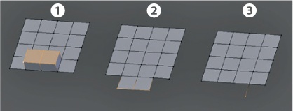
Extrude | E or CTRL-click | Creates new geometry by “pulling” new verts, edges, and faces out from the current selection. The results of extruding depend on what you have selected (see Figure 4-2). CTRL-clicking in Edit mode with nothing selected will create a new vertex wherever you click. Doing so multiple times will create a string of connected vertices. |
Fill | F | If two vertices are selected, Fill creates an edge joining them. If three, four, or more vertices are selected, it creates a tri, quad, or n-gon from them. |
Rotate | R | Rotates the vertices, edges, or faces you have selected. (You can also use the 3D Manipulator widget in Rotate mode.) |
Scale | S | Scales the vertices, edges, or faces you have selected, allowing you to resize part or all of a mesh. (You can also use the 3D Manipulator widget in Scale mode to do this.) |
Shrink/Fatten | ALT-S | Moves the selected vertices along the direction of their normals to inflate a mesh, almost like a balloon, or to shrink it to make it thinner. |
Smooth | W▸Smooth | Smooths sharp angles between edges and faces so that the resulting mesh is smoother. |
Subdivide | W▸Subdivide | Divides all selected edges into two and faces into four, creating more dense geometry. |
Translate (also known as Grab or Move) | G | Grabs the vertices, edges, or faces you have selected and allows you to move them. (You can also use the 3D Manipulator widget in Translate mode to do this.) |
Dissolve | X | An alternative to Delete, this deletes the edges or vertices selected but fills the hole left behind with an n-gon. |
Connect | J | Connects two vertices that are part of the same face, splitting the face in two in the process. |
Cut | K | Gives you a knife tool that lets you cut the selected geometry along the lines you draw. Hold CTRL to snap to vertices and the middle of edges. |
Note
Blender almost always has two ways of performing an action: through the UI and by using a keyboard shortcut and/or Search. In many cases, it pays to learn both because knowing how to quickly perform actions and switch between modes will greatly speed up your work.
Once in Edit mode, you can select things by right-clicking them. You can extend your selection with SHIFT-right-click. To select or deselect everything in the current mesh, press A. To switch between selecting vertices, edges, and faces, click the vertex, edge, or face select buttons in the 3D Viewport header (see Figure 4-1).
Press L to select all parts of a mesh connected to the part of the mesh under your cursor. With part of a mesh selected, you can perform various operations on your selection in order to edit your mesh.
Table 4-2 lists the operators that you’ll use most often when modeling in Blender. There are many other ways to interact with a mesh, but I’ll cover those as we go along.
To learn more about an operator in Blender, search for it on http://wiki.blender.org/. You can easily discover more operators (or search for an existing one) using the Search menu (spacebar) or by looking through the header menus and panels of Blender’s different editors. You can hover over buttons in Blender to see a tool tip describing what an operator does and whether it has a keyboard shortcut.
In Edit mode, the W key brings up a menu with a lot of handy tools for modeling. All of the operators you will use in Edit mode can be found in the 3D Viewport. As of Blender 2.5, when you use most operators, the Tool Options panel will appear at the bottom of the Tool Shelf, allowing you to change, retroactively, the parameters of the operator you just used. For example, after applying the Subdivide operator, you can use the Tool Options panel to change how many subdivisions to apply and whether to smooth them.
Other Ways to Model: Curves
You can use Blender to create models in a number of different ways, including using various curves, metaballs (which behave somewhat like blobs of clay that stick together when they get close to one another), NURBS surfaces (surfaces constructed from cross sections defined by curves), text objects, and Bézier curves. Each has its place in modeling, but the most important (after meshes) are Bézier curves, which we’ll use often throughout the modeling sections of this book.
Bézier curves define a path in 3D space and are constructed using control points and handles. They can be used to make both wire- or ribbon-like objects that follow the path of a curve (using closed or open curves) and flat surfaces that are defined by their outline (using closed 2D curves). Each control point has two handles that define how the path flows through that vertex, allowing you to create a wide array of smooth and sharp paths with a curve.
Modeling with curves works very much like using meshes; you can grab, rotate, scale, duplicate, and extrude control points or their handles. (You can’t make faces from curves, though; you can only connect each vertex in a curve to two others.)
When working with curves bear the following in mind:
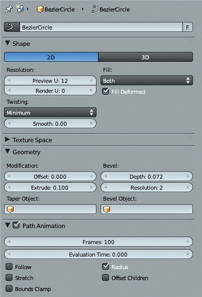
The geometry generated by curves is procedural. This means that the curves you define are used to generate a mesh according to the settings you apply to the curve in the Object Data tab (Figure 4-3) of the Properties editor. You can change things like the number of divisions per curve segment and the beveling and extrusion applied to the curve.
Curves can be open or closed. To close a curve, select its two ends and press F to join them. You can delete a segment of a closed curve by selecting two or more connected points and choosing X▸Segment to make it open again.
Curves can be either 2D or 3D. Points on a 2D curve cannot be moved along the curve object’s z-axis, which allows you to create a flat object by defining its outline with a curve. Blender then fills in the shape with faces according to the Fill setting (see Figure 4-3). You can then extrude the outline of a closed curve to create a solid shape using the Geometry settings in the Object Data tab. You can also add details like beveled edges and change the curve’s resolution here.
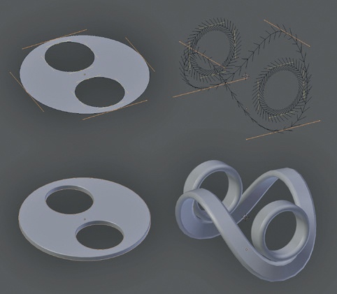
3D curves have a “tilt” that determines the direction of extrusion of the curve, as shown in Figure 4-4. You can see the direction of the tilt from the normals (arrowheads) displayed along the length of 3D curves. You can edit this tilt with CTRL-T, allowing you to create a curve that twists along its length.
Curves can be used to deform meshes. Mesh objects can be stretched along the path taken by a curve by applying a curve modifier to them.
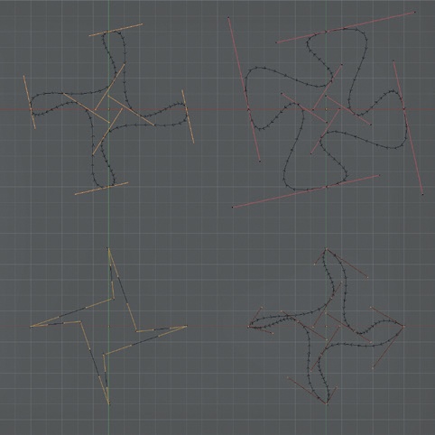
The curve handles can work in one of several ways, as shown in Figure 4-5. The default is usually automatic or aligned, depending on the sort of curve object you add. Automatic handles simply create a smooth path from one control point to the next, with the handles pointing in opposite directions. If you grab one handle and move it, its control point will switch to using aligned handles that point in opposite directions but can be rotated and scaled, allowing you to create more flexible curves. You can change to other handle types using the shortcut V (or via the Curve menu in the header). Vector handles create straight lines between points with sharp corners. Free handles create sharp corners too, but you can also grab them and move them around like aligned handles, allowing you to create curved segments between control points.
Modifiers
Modifiers allow you to procedurally and nondestructively perform operations on your models. They are fundamental to creating just about anything in Blender. Some modifiers generate new geometry, replacing or adding to your mesh, while others deform existing geometry according to certain rules or offer ways to plug simulations and other more complex entities into your scene.
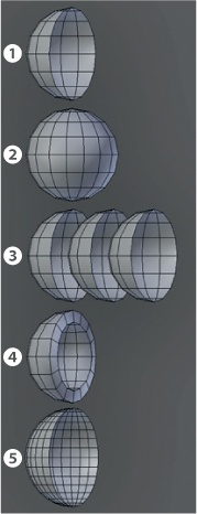
We’ll focus mainly on modifiers that generate and deform the meshes they are applied to because they’re the most useful for creating models. Some of the most important ones for modeling are listed in Table 4-3. In particular, the Mirror and Subdivision Surface modifiers are used in practically all organic modeling. The effects of the most commonly used generate modifiers are shown on a half-sphere in Figure 4-6.
Modifier | Effect | |
generate | Mirror | Mirrors the geometry of the mesh along the specified axis, about the object’s origin, or of another object. Mirror modifiers are very useful for creating symmetrical objects. |
Array | Copies the mesh geometry and offsets it using a fixed offset relative to the object’s size or some other object. Arrays are useful for models with repeating elements. | |
Subdivision Surface (Subsurf) | Divides each face of a mesh into four smaller faces and smooths them, creating a smoother mesh with each iteration. Subsurfs are useful for objects with smooth surfaces, particularly organic models. | |
Solidify | Extrudes the geometry along its normals to create a solid shell from a surface. | |
deform | Lattice | Uses a 3D grid of points to smoothly distort the shape of a mesh. |
Shrinkwrap | Projects the mesh onto the surface of another object. | |
Curve | Deforms a mesh along the path of a curve. |
Blocking in the Jungle Temple
Let’s consider the Jungle Temple scene. For this project, my initial concern was designing a layout for the environment that lent itself to creating a nice composition. I began with only the main elements in the scene: a door into the interior of the temple and some stone blocks and trees strewn around the ruins.
To create the door, I added a cube in Object mode (SHIFT-A▸Mesh▸Cube) and scaled it (S) to about the size I needed. Once you activate the Scale operator, you can constrain scaling along one axis (by pressing X, Y, or Z) to scale the object in only one direction. You can also scale on all but one axis by pressing SHIFT and X, Y, or Z.
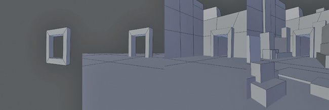
Switching to Edit mode (TAB), I added a hole by extruding in the two outside faces and scaling them on the x- and z-axes only. Next, I deleted the center faces (X) and created new faces around the hole in the center by selecting two open edges at a time and making a face between them (F), as shown in Figure 4-7.
Back in Object mode, I added a plane (SHIFT-A▸Mesh▸Plane) and scaled it up to form the ground plane of the scene. Then I added a camera and moved it to roughly view the door I was looking for. A quick way to do this is to navigate to the view you want just within the 3D Viewport and then press CTRL-ALT-0 to snap the camera to the current view. You can also just move and rotate the camera like any other object. Note that this might result in the camera getting slightly tilted. You can rectify this by manually setting the Y rotation of the camera to 0, using the Rotation properties in the Transform panel of the Properties region (N).
From here, I added some simple walls to form the main boundaries of my scene simply by adding, scaling, moving, and extruding cubes. Next, I began adding more cubes, keeping in mind how they would become the final architectural elements of the scene, like stone walls, statues, and loose blocks of stone. This progression is shown in Figure 4-8.
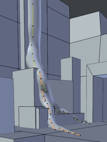
With the simple elements blocked in, I began to add rough proxies for the trees I wanted growing over the ruins. To create these proxies, I added a Bézier curve object and set the handles to automatic. Then I used Blender’s Snapping tools to extrude curves resembling the roots and trunks of trees over the surfaces of the placeholder objects (Figure 4-9). I accomplished this by turning on Snapping, setting the snapping target to faces, and enabling Project onto Surface (Figure 4-10). This projects the curves onto the other objects in the scene as you move and extrude them, allowing you to “draw out” the trees over the top of the existing scene.
Snapping
Blender has tools for snapping objects, vertices, faces, or edges to all sorts of things. To turn on Snapping, click the Snapping icon (the horseshoe magnet) in the header of the 3D Viewport (see Figure 4-10). Then, from the drop-down menu beside the Snapping icon, select how Blender will snap your selection when it’s moved, scaled, or rotated from among the following options:
Increment. Your selection will snap to the nearest increment so that you can construct objects with precisely aligned points. This is useful for modeling things like buildings or mechanical objects where you want perfectly aligned walls and floors with no lumps or bumps. (You can also snap your selection to Blender’s grid by pressing SHIFT-S▸Selection to Grid.)
Vertex/Edge/Face/Volume. Your selection will be snapped to the vertices, edges, faces, or interior of any objects. You can change what Blender chooses to snap to from the drop-down menu that appears. Click the icon to the right of the drop-down menu to rotate the selection so that it aligns with the normal vertices that it snaps to.
One very important snapping option is found in Face Snapping mode. Enabling Face Snapping causes the Project onto Surface icon to appear. Project onto Surface will cause geometry you create to snap onto the surface of existing objects as you move, scale, or rotate them around. This option allows you to create new topology over the surface of an existing object. In Chapter 7, we will be creating new topology over the surface of existing objects to better capture their shapes after we have sculpted the originals.
Base Meshes
To create the Bat Creature, I needed a simple base mesh that could be sculpted on. A base mesh is a simple model that captures the basic shapes of the model you want to sculpt. Once you’ve created a base mesh, you can add a Multiresolution modifier and begin subdividing and sculpting details in Sculpt mode (see Chapter 6).
Your base mesh should capture the overall proportions of the mesh and be designed to subdivide easily in order to provide a nice even mesh to sculpt on. We can retopologize the sculpted base mesh later to create the final model, but working with very simple geometry now will leave more freedom for experimentation while sculpting.
A base mesh can have any level of complexity, but try to create topology that will support the forms that you know you want to create, without introducing too many details that you might not be sure about. Depending on how sure you are of what you want your model to look like, you can include topology for features like eyes, mouths, and muscle groups, or you can leave it as simple as a basic sphere or cube if you’re just modeling a face.
For the Bat Creature, I aimed for a base mesh that gave topology for the overall body plan but left out fine details, such as the head. I developed the base mesh by setting my concept art as a background image and using it as a guide.
Building the Bat Creature Base Mesh
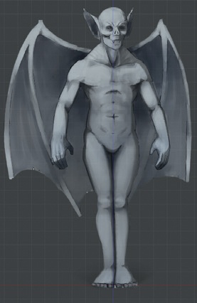
I started with the torso of the creature to provide a guide for the scale of the rest of the parts, as well as something to attach them to. To begin, I took the default .blend file (the scene you are presented with when Blender starts up) and deleted any objects already present. Then I loaded in the concept drawing for the Bat Creature (as shown in Figure 4-11). (For help with this, see Using Concepts and Reference Images in Blender.) While I didn’t plan to use this concept to model from exactly, it made a useful guide for judging the proportions as I worked. At this point, I left the wings out of the base mesh for the body, as I planned to model them separately later.
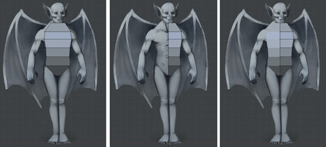
Next, I added a cube, changed to Edit mode (TAB), and scaled it to the rough proportions of the torso. I did this first in overall terms by just scaling it to the right width (S). Then I scaled up the z-axis (S▸Z) before scaling in on the y-axis (S▸Y) to make it taller and shallower. By adding horizontal loop cuts (extra rings of edges around the mesh, as discussed below) around the middle of the cube (CTRL-R) and moving them forward a little, I added a bit of curvature to the torso and began refining its shape.
At this point, it was easier to start using a Mirror modifier to keep my mesh symmetrical because the model was becoming more complex. To do so, I added a loop cut vertically around the middle of the torso and deleted its right-hand side. Adding a Mirror modifier then mirrored the geometry of the left-hand side of the body to create a symmetrical whole that only required editing on one side (see Figure 4-12). At the same time, turning on clipping keeps vertices on the midline from straying away from the object’s x origin, which prevents holes from appearing in the mesh if you accidentally move a vertex slightly away from the line of symmetry.
Loop Cuts and Face and Edge Loops
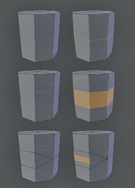
A face loop is a string of quads connected end-to-end in a continuous path, allowing an edge loop (a chain of connected vertices) to be cut through the middle. For example, in Figure 4-13, adding two edge loops around the face loop encircling the cylinder creates a new face loop running around the middle. Technically, an edge/face loop should be one continuous cyclical path, but the term is often used to mean any reasonably long chain of quads/edges.
The Loop Cut tool (CTRL-R) is extremely important because it follows a path of quads through your mesh, cutting through each one to create new edges that flow through the face loop. If you activate the Loop Cut tool and mouse over an edge, Blender will highlight the path in purple. If the path reaches a triangle or an open edge of the mesh, it stops.
Loop cuts are useful because they allow you to add definition to your model while maintaining clean topology. You can create multiple loop cuts by scrolling your mouse wheel after pressing CTRL-R and before choosing an edge to start cutting from (see Figure 4-13).
Blender has other operators for interacting with edge loops and face loops, including ones for deleting the loop (joining the faces on either side together to keep the mesh whole) and sliding the loop up and down the edges parallel to it. You can also select an entire edge loop at once to manipulate it. (If it isn’t cyclic, Blender will simply find the longest path that it can.) These operators are detailed in Table 4-4.
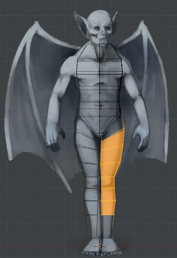
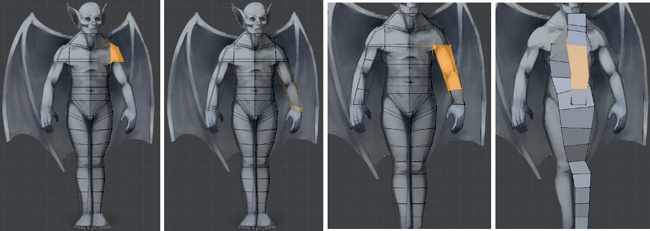
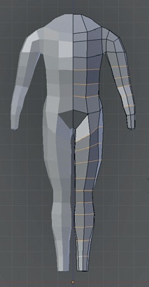
As the next step in my project, I extruded down from the hips to make the leg and added loop cuts to flesh out its shape, as shown in Figure 4-14. For the arms, I added a bend at the shoulder by extruding out from the body and then down from the bottom face of the newly extruded region, as shown in Figure 4-15. This gave the shoulder a nicer, more natural corner than it might have if I’d extruded down directly from the body.
Operator | Hotkey | Function |
Delete Edge Loop | X▸Edge Loop | Deletes the selected portion of an edge loop, leaving the surface otherwise intact. |
Edge Slide | CTRL-E▸Edge Slide | Allows you to slide all or part of an edge loop along the edges running perpendicular to it. |
Loop Cut | CTRL-R | Creates a new edge loop starting from the edge under the cursor. |
Select Edge/Face Loop | ALT-right-click | Selects an edge/face loop (depending on selection mode). |
Poses for Modeling Characters
The pose you model a character or creature in is very important to its ultimate look, and your strategy will depend on what you want to use your model for. So far, I’ve modeled the Bat Creature in a relaxed pose that is close to the classic T pose: arms straight out and legs shoulder width apart. The T pose is useful when rigging a character (the process of creating an armature that tells the mesh how to move as if it had bones and joints). However, the T pose looks rather tense and unnatural when modeling, an effect that can stick around when posing a character into other positions. Instead, I wanted the character to look as relaxed and neutral as possible while in the early stages of modeling so that I could progress away from this neutral position later. By relaxing the arms down toward the character’s sides, I eliminated this tension to make the character’s default pose much more natural.
Note
Though we won’t cover rigging in detail, note that there is a reason for the classic T pose. When it comes to rigging, having a character’s arms out straight can make it simpler to set up bone chains and constraints. However, continuing improvements in Blender’s rigging tools have made it somewhat less necessary to do this. You can always re-pose your model in the T pose after having modeled and sculpted it in a more relaxed pose.
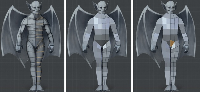
Next, I selected all the edges running down the front and back of the body and legs and subdivided them (W) to allow me to refine the shape of the torso and legs. Doing so created some awkward topology at the pelvis, which I fixed by selecting the two new edges and merging them, as shown in Figure 4-16. I did the same for the edges on the backside, too.
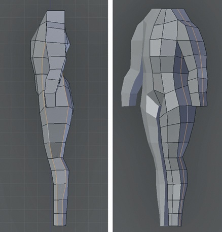
I added an edge loop around the middle of the character as seen from the side (Figure 4-17) and running across the chest and down the arms. I then further refined the body shape, tucking in the waist at the back and rounding out the shape of the legs and arms. This step brought the number of vertices around the arms and legs to a total of eight, which would be important when adding hands and feet.
As I went along, I tried to make sure that my mesh was completely composed of quads, and I aimed to keep the size and shape of the quads approximately even and square. This is important when creating a base mesh for sculpting because triangles, n-gons, and long, thin faces generally create artifacts when sculpted on.
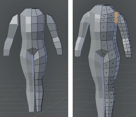
To create a loop of faces running around the shoulder (Figure 4-18), I selected the faces of the arm and split them from the body (Y). I then shifted the arm out and bridged the edges around the gap using the Bridge operator (W▸Bridge Two Edge Loops). This connected two strings or loops of vertices together, filling them in with faces from one to the other. The two must have the same number of vertices to be joined.
Then I added some more loop cuts over various parts of the body, running across the forms, to even out the mesh and give an even distribution of roughly square quads (Figure 4-19). You can adjust the position of an existing edge loop using the Edge Slide operator (CTRL-E▸Edge Slide), which lets you slide edge loops up and down.
Modeling the Hands and Feet
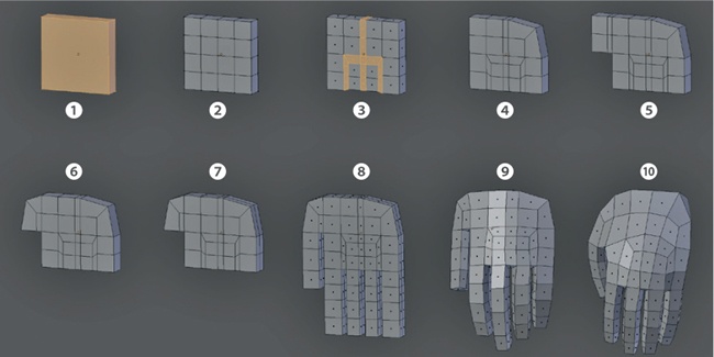
To model the hands (as shown in Figure 4-20), I began with a cube and flattened it by scaling it down along its x-axis to form the basis for the palm 1. Then I added some loop cuts around the middle and vertically 2.
At this point, I could have extruded the fingers straight out from each face at the base of the palm. Doing so, however, would have created some nasty topology where the fingers meet each other that would neither sculpt nor deform well when posed. Instead, I did some extruding to add face loops that run between the fingers 3. For the middle one, I simply selected half of the hand and extruded out. For the outer two gaps, I extruded in the middle 4 faces on the bottom half of the hand on both sides, as well as those connecting the two sides along the bottom, for a total of 10 faces.
To reduce the number of faces along the top side of the hand (where it will eventually join with the arm), I merged the two pairs of edges on the top corner of the hand opposite the thumb 4. (Remember I was aiming to have eight vertices to join with the arm, so this area needed to be kept simple.)
For the thumb, I extruded out twice from the faces on the front of the hand 5 and then merged the vertices on the corner to create a bend 6. I then added a loop cut running around the outside of the hand 7, extruded the fingers and the thumb 8, and smoothed them slightly (W▸Smooth). Next, I gave the fingers and thumb a bit of a curl inward by selecting and first rotating the whole finger, then the last two-thirds, and then just the tip 9. I also adjusted the shape of the whole hand by selecting parts of the hand from the top view and rotating them with proportional editing turned on to give the palm and thumb a slight curve.
I smoothed the hand slightly (W▸Smooth) to make the fingers and palm a bit less blocky. By selecting the surface of the palm, and with proportional editing turned on, I inflated it slightly (ALT-S) to give the hand a bit more volume 10. This completes the modeling stages shown in Figure 4-20.
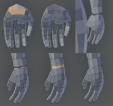
To connect the hand to the arm (Figure 4-21), I deleted the four faces in the middle of the top side of the hand, moved the hand into place, and then joined the hand with the main body in Object mode (CTRL-J). Then in Edit mode, I deleted the corresponding faces at the end of the arm and bridged the loops to connect the hand to the arm.
Because I kept the number of vertices around the end of the arm and the wrist the same, the hand joined to the arm with a minimum of fuss, as shown in Figure 4-21. Because the join now had two edge loops quite close together, I deleted one (selecting it with ALT-right-click, then deleting with X▸Edge Loop) to create a more even distribution.
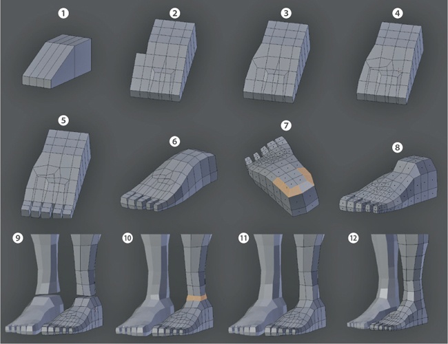
Modeling the feet was much the same, as shown in Figure 4-22. Beginning with a cube, I first extruded the general shape of the foot 1. I added face loops to produce gaps between the toes (2 to 4), extruded the toes 5, smoothed the foot a little 6, and then merged the corner edges on the back of the foot to improve the way that the edge loops flow around the back and reduced the overall polycount, as I did with the hand 7. I used Inflate and proportional editing to make the big toe bigger and refine the slope of the foot, which slopes down forward from the leg and down from the big toe side to the little toe side 8. Again, because there are eight vertices around the circumference of the leg, I could delete four faces from the top of the foot and bridge the gap with the leg (9 and 10). Then I cleaned up the edge loop distribution along the lower leg by sliding, deleting, or adding edge loops to get more evenly spaced edge loops (11 and 12).
Modeling the Head
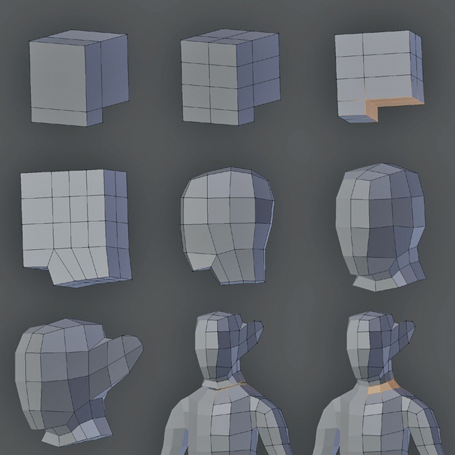
The head began as just a cube extruded out, once at the front and then down at the base to create the chin (Figure 4-23). After adding a few loop cuts, I extruded out from the bottom to create the neck and then smoothed and refined the shape to give it a better silhouette and to make it slightly narrower at the front. I extruded out from the faces on the side of the head to create some geometry for the ears. Then, as with the body, I deleted half and added a Mirror modifier. Next, I connected the head to the body, deleting the faces in between and bridging the gap with the Bridge operator.
Tweaking the Model with Proportional Editing
If you don’t like the proportions of certain areas of your model, you don’t have to tweak every vertex individually. Instead, you can use Blender’s proportional editing to grab, scale, or rotate one vertex and drag nearby vertices along with it so that changes are made proportionally.
To turn on proportional editing, use the circular icon in the 3D Viewport header (as shown in Figure 4-1) or the shortcut key O. Once proportional editing has been turned on, you can adjust the distance over which the nearby unselected vertices are dragged (along with selected ones), as well as the falloff curve for the effect. To change the radius, scroll your mouse wheel while manipulating your selection. Select the falloff curve from the drop-down menu next to the Proportional Editing icon in the header. You can also set proportional editing to affect only connected vertices (ALT-O), which will drag only nearby vertices in the same mesh as those selected, allowing you to do things like move an arm without affecting your model’s waist.
Different falloff settings can significantly impact the effect of transforming part of your mesh. For example, the Sharp Falloff option will create sharp peaks if you grab and move a single vertex, whereas the Sphere Falloff option will create bulbous, spherical shapes. The Random Falloff option is useful for roughening up the surface of a mesh; by grabbing a single vertex and moving it a little, with a wide radius for the falloff, you can add a slight random variation to the surface of a mesh.
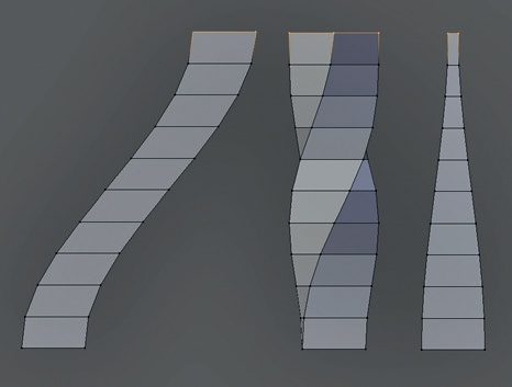
Proportional editing is useful for many things besides tweaking proportions. For example, you can use it to create interesting curved or twisted deformations by grabbing or rotating parts of the mesh (Figure 4-24) or for posing characters without having to rig them.
I used proportional editing to make a few tweaks to finalize the mesh, such as pulling back the arms and shoulders slightly and narrowing the back where it’s level with the waist.
Creating the Wings
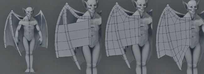
To make it easier to sculpt on the body and wings, I created them as separate meshes that I could join later when retopologizing. To create the wings, I first blocked in the skeleton using the reference as a rough guide, beginning with a small plane and working along the length of the bones (see Figure 4-25). To make it easier to get the topology I wanted, I kept the mesh 2D at this point.
With the basic skeleton blocked in, I began filling in the wings between the bones. To make sure the gap could be filled in neatly, I spaced out the vertices along the bones so that they roughly matched up with one another, adding more as needed or shifting existing ones. Next, I extruded and scaled the edges to create a clean division between the wing and the bones, and I began filling in the gaps. (The extrusion/scaling won’t produce perfect results, but you can tweak the position of the vertices manually to get a nicer layout.)
With the gaps filled in, I selected the whole model and extruded it back to give it some thickness, as shown in Figure 4-26 1. Next, I selected just the wing membrane areas and used the Shrink/Fatten tool (ALT-S) to make these areas slightly thinner again 2. At this point, the wing had some thickness but was still very flat looking. To rectify this, I first selected its more central parts and shifted them back slightly to give the wing a bit of a concave shape 3.
Note
Sometimes Blender will calculate the normals of a mesh incorrectly, which can cause operators like Shrink/Fatten and modifiers like Subdivision Surface or Bevel to behave strangely. You can often see this if you set your mesh to draw smooth, as black boundaries will appear between areas with conflicting normals. To fix this, simply select your whole mesh in Edit mode and use the Recalculate Normals operator (CTRL-N) to force Blender to recalculate the object’s normals.
Next I used the Warp operator (SHIFT-W) to give the wing a curve 4. This operator uses the 3D cursor position as the center of the operation and arranges the selected vertices in a circle around that center. You can define how far the vertices are warped with your cursor; setting the 3D cursor further from the mesh before using the operator will give the curve a wider radius.
As a result of these treatments, I was able to add a nice curve to the wing by switching to the top view and using Warp. Also, by rotating the mesh and using Warp again, I could add a similar curve to the wing’s profile 5.
The Warp operator will often move the mesh about a bit, so I dropped back into Object mode (TAB) and moved the wing back to where I wanted it before applying the transforms (CTRL-A▸Apply Location and then repeat for Rotation and Scale, too).
Applying Transforms
Operations like Warp can move your object out of place and require you to rotate, scale, or translate your mesh to put it back in place. It’s often easiest to do this by moving the entire mesh at once in Object mode, though doing so will also affect the object’s local coordinates, which can lead to strange results when using operators and modifiers. For example, I next wanted to use a Mirror modifier to copy the wings over onto the other side of the base mesh for the Bat Creature, but after using the Warp operator and moving and rotating the wings in Edit mode, adding a Mirror modifier would have given incorrect results (see Figure 4-27). The reason for this is that by rotating the object in Object mode, I rotated its local coordinates, too. Because the Mirror modifier uses these coordinates to mirror the object, the results were not what you might expect.
To see an object’s local coordinates, turn on the Axes setting in the Object tab of the Properties editor (see Figure 4-27). To reset the axes to match the global coordinate system, use each of the Apply Location/Rotation/Scale operators in Object mode (CTRL-A) in turn, which will place the object’s origin at the global origin and match the rotation and scaling of its local coordinates to the global coordinates without affecting its shape. As a result, you’ll be able to model, add modifiers, and perform other operations with more predictable results.
Note
Of course, instead of the above, you can manipulate an object’s local coordinates to your advantage. For example, you could use a Mirror modifier to create a symmetrical object and then move and rotate it to a position in your scene that doesn’t match the global coordinates. As long as you don’t apply these transforms in Object mode at this point, the results of the modifier should stay the way you want them to.
Finally, as with the body, I added a Mirror modifier and then used proportional editing to better align the wings with the back and tweak the shape.
At this point, I had completed blocking in the bat’s body, as shown in Figure 4-28. We’ll create its final topology once the sculpting is finished, as discussed in Chapter 5 and Chapter 7.
Shading Modes
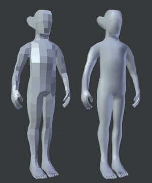
Notice that so far in blocking out the projects, I have kept the meshes we have been creating shaded flat—that is, the faces appear faceted and do not blend into one another. The reason for this is that it makes it easier to read at a glance the direction that the faces of a mesh are pointing and to see how the forms of the mesh are progressing. Later on, I will use smooth shading to render some of the models in order to make them look smooth (Figure 4-29), but for now this isn’t necessary. To switch between the two, simply select your mesh, and in the Tool Shelf, use the Flat and Smooth operators to switch the shading of your selection between flat and smooth shading. You can do this either in Object mode, which affects the whole of each selected object, or Edit mode, which affects only the selected faces.
Creating the Spider Bot
To block in the Spider Bot, I needed only the basic parts of the body and legs. To generate more detailed ideas for the main parts of the body, I used sculpting and then retopologized the results and added more mechanical parts with traditional modeling.
Beginning with two cubes, one for the abdomen (back segment) and the other for the cephalothorax (head and body segment), I scaled them roughly to the correct proportions, as shown in Figure 4-30 1. By adding a Subsurf modifier (CTRL-1), I was able to get a more rounded shape without having to add and manually adjust lots of edge loops. Just adding a couple more edge loops brought me closer to the shapes I needed 2.
After joining the two cubes into the same object in Object mode (CTRL-J), I applied the Subsurf modifier at subdivision level 1 to give more geometry to play with 3, but I copied the modifier first to further subdivide the mesh. When a modifier is applied, changes it makes to the mesh are applied to the mesh and thus converted into geometry you can edit. This allowed me to extrude some of the new faces from the front of the body to create a bump for the head 4. With the extruded faces still selected, I pressed CTRL-+ to grow the selection, fattened it a bit with ALT-S, and then smoothed it a little to complete my base mesh for sculpting the body.
For the legs, I began by laying out my plan for the main part of the leg, consisting of long, flattened, bone-shaped pieces for the long segments of the leg and shield-shaped pieces for the knee and foot segments. I created two slightly different variations of the long segments, one for the first and last pairs of legs and one for the middle two pairs 5. To create these pieces, I began with a plane, added a Mirror modifier to make the leg symmetrical, and then extruded one edge and added loop cuts to create the top-down plan of the leg. Next, I selected the whole thing (A) and extruded it out along its normals by first extruding (E) without moving the new faces. I then moved the new faces along their normals (ALT-S) to give the leg segment a uniform thickness. For now, I created only one copy of each piece; after sculpting and retopology, I’ll duplicate the finished parts and position them to make the legs. This completes some basic parts for the Spider Bot.
In Review
This chapter laid the foundations for the models. For the Spider Bot and the Bat Creature, this entailed creating base meshes with simple topology that we’ll later use to sculpt on and flesh out the designs of our characters. In the case of the Jungle Temple, I blocked in the most important elements of the scene with simple placeholder meshes. In the next chapter, we will replace and expand upon these placeholders, as well as model some extra details for the other two projects and discuss some more in-depth modeling concepts along the way. Then in Chapter 6, we will move on to sculpting the base meshes created in this chapter using Blender’s sculpt tools.
