Soldering
In this chapter, I will first give a simple introduction to soldering of through-hole PCBs and then look at the more difficult but still perfectly possible soldering of SMD boards.
![]()
You do not have to spend a lot of money on tools for soldering PCBs. You can get perfectly good results with low-cost equipment. You wouldn’t learn the violin on a Stradivarius, so don’t buy a top-end Weller soldering station as your first soldering iron. Gradually improving your tools is one of the joys of electronic construction. Where would the fun be if you had the best of everything from day one?
However you plan to do your construction, you will need certain tools when soldering a PCB.
Snips (essential) are used to cut the excess leads off components after they have been soldered. They are sharp and allow you to get close to the solder joint. They are also useful for stripping the insulation off wire. Eventually, snips lose their sharpness and become blunt, especially if they are abused by being used to cut steel guitar strings. I use very cheap snips (Figure 7-1) and then replace them as soon as they become blunt enough to be irritating to use.
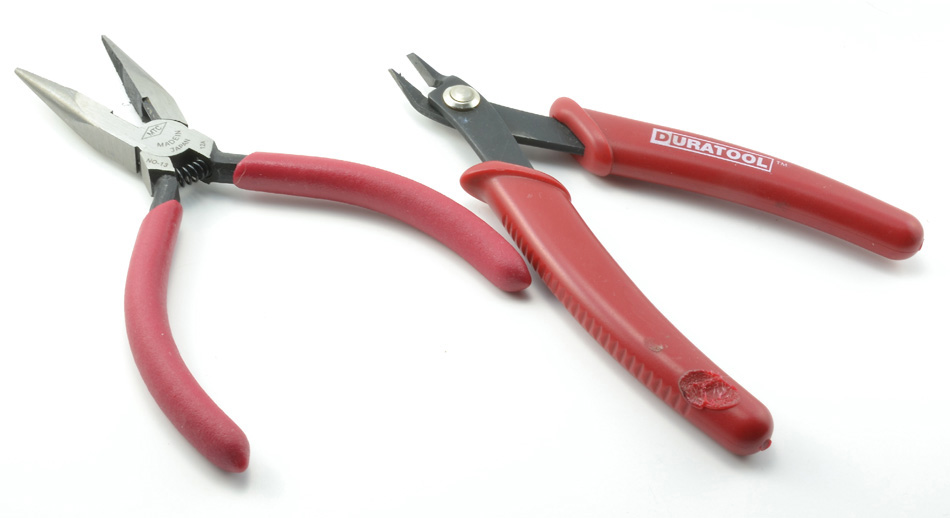
FIGURE 7-1 Snips and pliers.
Long-nosed pliers last longer and are generally a useful tool to have around. They can be used to grip a wire tightly while you strip the insulation from it or for holding onto a components that you are trying to desolder from a board without burning your fingers.
In a perfect world, everything would work the first time when you powered it up. The reality is that life is not quite like that. A multimeter (Figure 7-2) is an essential tool that will allow you to diagnose problems with your designs.
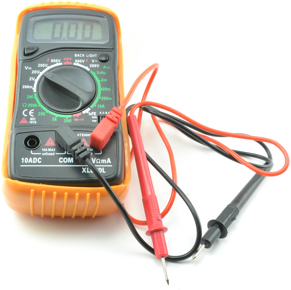
FIGURE 7-2 Multimeter.
You do not need to spend a lot of money on a multimeter. A basic entry-level multimeter costing just a few dollars will do just fine most of the time. The most important setting that you will use most of the time is direct-current (dc) volts in a range of 0 to 20 V.
It is also useful to have a dc current setting of up to a few hundred milliamperes and a continuity test that buzzes when the test leads are connected together. Everything else is just bells and whistles that you might use once in a blue moon.
Most of the time, accuracy is pretty irrelevant too. When things go wrong, it is usually a matter of orders of magnitude. Thus, if your multimeter indicates a current of 10 mA when the current is actually 12 mA, that is usually good enough. It’s when the current is 100 mA and you were expecting 10 mA there is a real problem.
Although you can get by with a soldering iron that plugs directly into an alternating-current (ac) outlet and has no way of adjusting the temperature, it is worth spending a few extra dollars on something that is thermostatically controlled and can accept fine-pointed tips (Figure 7-3). Make sure that you avoid anything advertised as being suitable for plumbing use.

FIGURE 7-3 Low-cost soldering station.
When you are buying your soldering station, bear in mind that eventually the tips (also called bits) will need replacing. Make sure that replacements will remain available, or buy them when you buy the iron. With the trend that components are getting smaller and smaller, you probably will want a tip of perhaps 2 mm. There are many different tip shapes, and choice is a matter of personal preference. Many people prefer a chisel-shaped tip. A simple conical tip is another popular choice.
If you plan to use lead-free solder, then temperature control is a must. You can get away with a simple low-cost soldering iron if you are using solder with lead in it because this type of solder is much easier to work with (see next section).
WARNING It should go without saying that soldering irons get hot enough to burn your skin. Be very careful, and always put the soldering iron back into its holder as soon as you have finished with it. Do not leave it on the desk to roll off, triggering the automatic instinct to try to catch it when inevitably its lead gets snagged and it falls off the desk. Soldering also produces fumes from the rosin flux. It is a good idea to solder next to an open window or use a fume extractor.
Traditionally, solder (Figure 7-4) has been made from tin and lead. Usually, this is in the proportion of 60 percent tin and 40 percent lead. The solder looks like a solid metal wire, but actually will normally have a core of flux rosin that helps the lead to flow when it melts. Legislation on the use of toxic chemicals has resulted in a reduction in the use of lead-based solder in favor of lead-free solder.
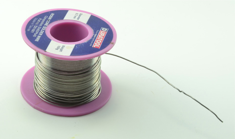
FIGURE 7-4 A reel of 0.7-mm tin, lead solder.
This type of solder is an alloy of tin, silver, copper, and small amounts of other metals. It looks like lead solder and still has a rosin core but is somewhat brittle and has a melting temperature of about 200°C (392°F) versus about 190°C (374°F) for leaded solder.
The differences do not end there. Many people find lead-free solder much harder to work with. It does not flow as easily as lead solder.
Lead solder is still widely available, and unless you are producing a product that you are going to sell, it is really a matter of personal preference which type of solder you use. I know electronics enthusiasts who have a roll of lead-free solder that they use most of the time and then a roll of the “good stuff” (lead solder) that they use when they have something tricky to solder.
Whatever type of solder you use, you will have another choice to make: the gauge of the solder you buy. Two popular sizes are 0.7 and 1.2 mm in diameter. Use 0.7-mm or similar solder when integrated circuit (IC) leads are close together, for example, because it is much easier to use. If you need to solder some large terminals, you will find yourself feeding in quite a length of the narrow solder to deliver the required amount, but this is not really a problem.
Desoldering braid (Figure 7-5) is not an essential tool for soldering, but it can come in very handy from time to time. As well as its primary use for “unsoldering” components, it is also great for mopping up excess solder, especially when hand soldering SMDs.
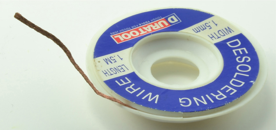
FIGURE 7-5 Desoldering braid.
The braid is made of copper impregnated with flux that encourages the solder to flow. Thus, when you place it between the pad from which you want to remove the solder and the soldering iron tip, it soaks up the solder like a sponge. Having done this, that section of braid cannot be reused, and you snip it off and throw it away.
When you solder, it is very important that the tip of the iron is clean, or you will end up with blobs of solder that do not make a good joint. There are two methods of cleaning the tip, both used with the soldering iron hot. One is to use a damp sponge, and many soldering stations include a sponge holder. The other is to use a container of brass shavings, rather like a scouring pad (Figure 7-6).
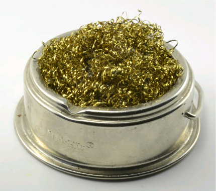
FIGURE 7-6 Brass soldering iron tip cleaner.
The only real advantage of using a damp sponge is that it makes a great hissing noise as the hot tip of the iron is rubbed across it. It does, however, suffer from a number of disadvantages:
• The thermal shock of cooling the tip quickly as it comes into contact with the wet sponge will shorten the life of the tip.
• You have to keep wetting the sponge and need a supply of water.
When attempting surface-mount soldering by hand, you probably will need all the equipment that I have just described for through-hole soldering. In fact, you can get away with just using regular soldering equipment. However, there are a number of special items that make surface-mount soldering simpler.
A hot-air gun (Figure 7-7) has interchangeable nozzles of different sizes that allow you to deliver a stream of hot air to an area of a circuit board.

FIGURE 7-7 Hot-air gun.
You can normally set both the temperature of this air and the flow rate. You will need to control the flow rate because many SMD components are so small that they can easily be blown away by the pressure of air from a hot-air gun.
When soldering SMDs, you can, with care, use regular solder. However, if you are using a hot-air gun or a reflow oven, then you will need to use solder paste (Figure 7-8). Solder paste is available in both lead-based and lead-free varieties and suffers the same pros and cons as those variants of regular solder.

FIGURE 7-8 Syringe of solder paste.
Solder paste is made from microscopic spheres of solder in a suspension of flux. For industrial use, it is supplied in tubs, but for small-scale use, you can buy it in syringes ready for hand use. Solder paste should be kept in a refrigerator but warmed up to room temperature when you are read to use it.
WARNING Solder paste is a liquid, and if you are using lead-based solder paste, it will easily find its way into the pores of your skin if you get it on your fingers. Always wear latex gloves if, like me, you are a bit messy and likely to get it on your fingers.
To be able to pick up and place SMDs onto a board, you will need tweezers (Figure 7-9).
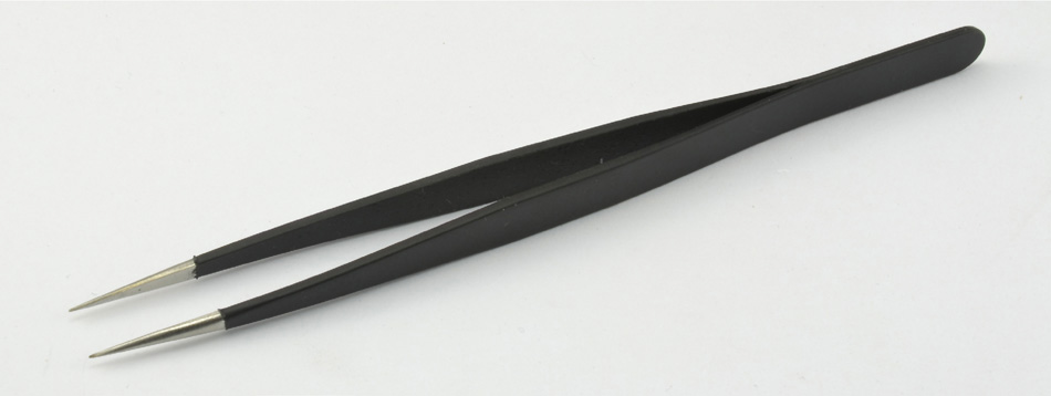
FIGURE 7-9 Nonmagnetic tweezers.
The tweezers should have a fine point and, most important, be nonmagnetic. If they are even slightly magnetic, then SMDs will stick to them because many contain ferrous metals.
It can be really hard to see what you are doing when you are working with surface-mount technology (SMT). A large magnifying work lamp such as that shown in Figure 7-10 can be a great help.
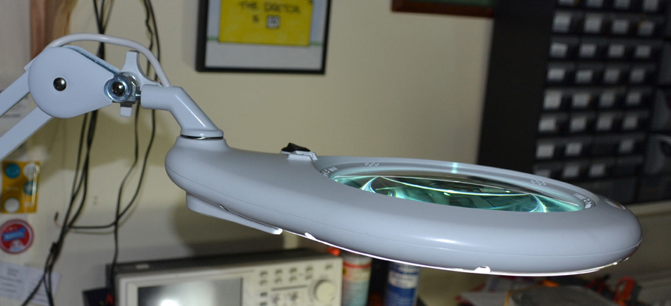
FIGURE 7-10 Magnifying work lamp.
These devices have a lighting ring around the lens that evenly illuminates the board on which you are working. Because you are looking through the lens with both eyes, all-important depth perception is preserved.
Some people take this a stage further and use a binocular microscope. These are available specifically for working on circuit boards, and a zoom version will allow you both to work on boards and to inspect them very closely for any problems. You should look for something that magnifies between 5 and 20 times.
When developing single boards, hand soldering works okay. It is a little tedious and time-consuming but can be done. The professional way to attach SMT components to a board is to use a reflow oven.
The basic idea is that you put solder paste on the pads of the board, place the components onto the pads, and then bake the entire board in an oven to melt the solder paste and attach the components. We will see how to do this in a later section.
Commercial reflow ovens are quite expensive, but many people make their own using low-cost toaster ovens, such as the modified device of the author’s shown in Figure 7-11.
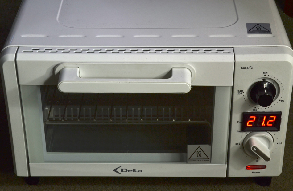
FIGURE 7-11 Modified toaster oven.
WARNING These types of toaster ovens are often called “fire starters” for good reason. They are very simple designs, with little in the way of thermal insulation. This means that they get very hot, and if you modify them, they can become even more dangerous. If you decide to make one of these, never leave it unattended or anywhere near anything that could burn.
The model shown in Figure 7-11 has been modified to replace the thermostat with a proportional power control module, and a digital thermometer has been added to allow the necessary accurate monitoring and control of temperature.
![]()
Having explored the various tools we will need, let’s start by learning how to solder through-hole PCBs. It is a good idea to try to follow these instructions on a PCB. You may wish to order one of the PCB designs from earlier in this book. We will use the sound meter design. Having a batch of PCBs means that you can sacrifice one or two on which to practice your soldering.
The first thing to do is to turn on your soldering iron and set the temperature. You will find conflicting advice for temperatures to use, but I set my soldering iron to 280°C (536°F) for lead-based solder and to 310°C (590°F) for lead-free solder. Once you get your eye in with soldering, you probably will want to work at a higher temperature, where the solder melts a bit more quickly. The higher temperature will not damage the components as long as you are quick.
When the soldering iron is up to temperature, clean it on the damp sponge or brass tip cleaner. Once cleaned, it should look bright and silvery.
The key to soldering is not to heat the solder but rather to use the soldering iron to heat the place where you want to solder and then feed solder onto that junction so that it melts and flows over the pad and the component lead. Figure 7-12 shows the steps involved in soldering the resistor leads.
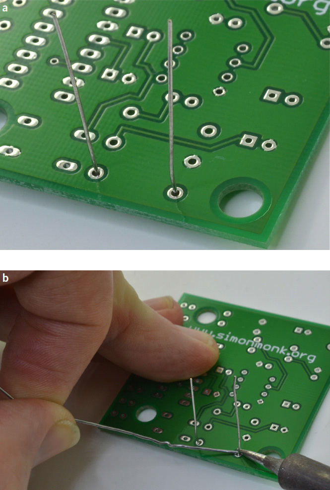

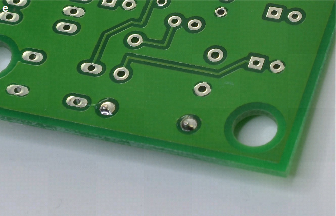
FIGURE 7-12 Soldering a resistor.
First, push the component leads through their holes, and turn the PCB on its back (Figure 7-12a); then hold the tip of the soldering iron to the junction of the pad and the lead. Next, feed solder into the joint so that it flows all around the lead and covers the pad (Figure 7-12b). Once it has flowed all around, you can stop adding solder and move the tip away. You do not want the pad to be heaped high with solder. The solder ideally should form a nice “mountain” of solder around the lead (Figure 7-12c). Finally, you can snip off the excess lead (Figure 7-12d and e).
When soldering components onto a PCB, you can make life much easier for yourself if you start with the components that lie closest to the surface of the board. In this way, when you turn the board on its back, the weight of the board will keep the components pressed against the board.
If you make a mistake and find yourself needing to desolder a joint, then Figure 7-13 shows the steps you should take.
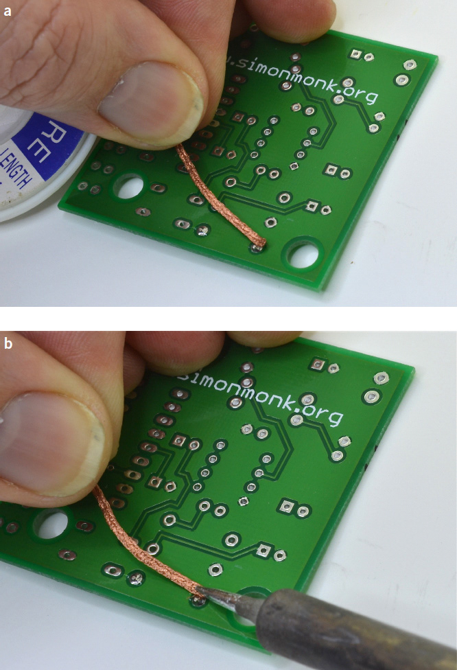
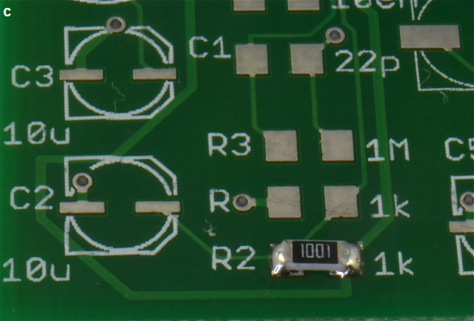
FIGURE 7-13 Desoldering.
If the board was soldered some time ago, then you might find that it is quite hard to desolder. Actually heating it and adding a bit of solder could make it easier to desolder the component. Thus, after optionally resoldering the joint as described earlier, place an unused end of the soldering braid against the joint (Figure 7-13a), and then press it down onto the solder pad using the tip of the soldering iron (Figure 7-13b). As the solder melts, it should be drawn into the solder braid. You will be lucky to draw off all the solder in one go, so most likely you will need to snip off the now-solder-covered end of the braid and repeat the process of pressing it against the joint. Eventually, you should have most of the solder removed, and the joint will look like Figure 7-13c.
Repeat this for the other lead or leads of the component. If you are very lucky, you will just be able to wait until the component has cooled and then gently pull the component back through the hole from the top. However, it is more likely than not that there will still be a little solder holding the component in place. If this is the case, then hold one component lead from the top side with long-nosed pliers, and heat the pad from underneath while applying a gentle pull on the lead to pull it back through. If you cannot get to the lead and you don’t mind breaking the component, then snip it in half or snip the lead off on the top to make it easier to pull through.
All this means that you are likely to be heating the board for a while, which can make it look scruffy or even damage the board. Pulling the lead through with force is also likely to damage the PCB, and ultimately, too much heat will eventually cause the pad to separate from the board.
![]()
As long as the SMDs you use are at the larger end of the size scale and have pins on the edges of the device rather than on the underside, then they can be soldered relatively easily using a regular soldering iron. The main problem is that they are so light, and because they do not have leads projecting through the holes, there is nothing to hold them in place when you try to solder them.
The sequence of steps to solder a 1206 resistor into place is shown in Figure 7-14.
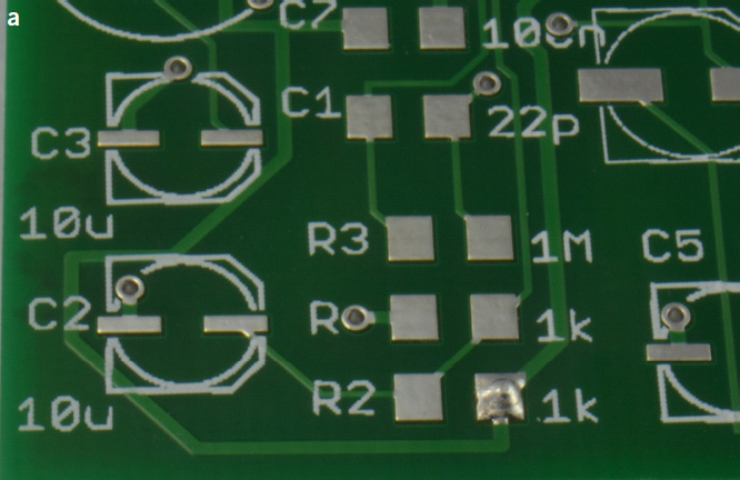

FIGURE 7-14 Using a soldering iron on an SMT resistor.
This is one of those situations where you would really benefit from having three hands—one to hold the soldering iron, one to hold the tweezers to keep the SMD in place, and one to apply the solder. If you do not have three hands, then a good trick is to place a small mound of solder on one of the pads (Figure 7-14a) and then, while holding the SMD in place with the tip of your tweezers, press its lead into the little solder mound (Figure 7-14b) with the tip of your iron. The SMD will now stay in place without the need of the tweezers as you solder the other end normally (Figure 7-14c). It’s then usually a good idea to touch the first end with the iron and a little solder just to freshen it up.
An alternative technique is to place solder paste onto the pads, hold the SMD in place with the tip of your tweezers, and then touch the tip of the iron to each lead until the solder paste beneath melts.
The preceding approach works just fine for two- and three-legged devices, but when it comes to ICs, the process can become more tricky. You can try the conventional soldering iron approach, pinning the IC down with one corner pin and then carefully soldering the remainder of the leads, but often the solder will make unwanted bridges between the pins.
A good trick is not to worry too much about those bridges, but when you have finished soldering, lay desoldering braid along the row of pins and heat along the whole length to remove the excess solder. This is shown in Figure 7-15.
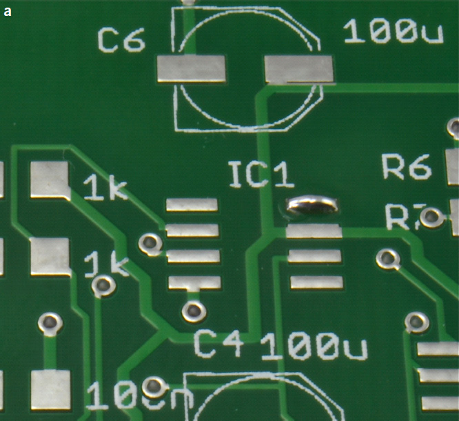
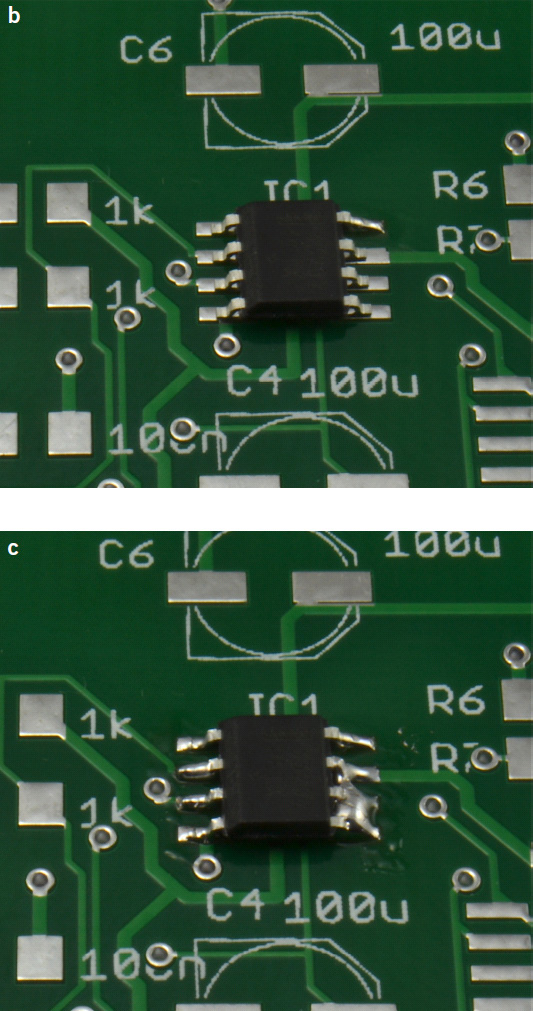
FIGURE 7-15 Hand soldering an SMT IC.
![]()
Generally speaking, it is much easier to solder SMDs with solder paste and a hot-air gun than with a soldering iron.
The steps for soldering with solder paste and a hot-air gun are illustrated in Figure 7-16.

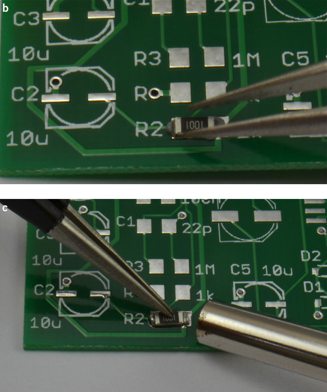
FIGURE 7-16 Soldering with a hot-air gun.
First, place a small amount of solder paste on each pad. You can either squeeze it out through the syringe needle or use clean gooey paste, wiping away any crusty paste from the end of the syringe before you start (Figure 7-16a). Occasionally, I find a wooden toothpick to be useful for spreading the paste around a bit. Do not worry if it is a little untidy; when it melts, surface tension will cause it to pull back onto the solder pad.
Next, using your tweezers, place the component onto the pads (Figure 7-16b). Now fit a small nozzle onto your hot-air gun, set the temperature to 280°C (536°F) for lead-based solder and 310°C (590°F) for lead-free solder, and set the flow rate to perhaps one-quarter of full power. When the air gun is up to temperature, pin the component down with the tip of your tweezers, and then play the hot-air gun over the component and its leads until the solder paste melts (Figure 7-16c). When the solder melts, you will see it change from dull gray to shiny silver and see it spread across the pad. While still pinning down the component, put the hot-air gun safely back on its stand, and after a second or two, when you are sure the solder has set, let go with the tweezers.
If you do not hold the component in place with tweezers, then even at very low airflows, the hot-air gun probably will blow the component out of position.
Soldering ICs is very similar to the process just described. The only real difference is that you may well want to clean up the connections using soldering braid, as shown in Figure 7-15.
Some IC packages have inaccessible components on their underside. To solder these, put paste on the pads as normal, and then while you hold the IC in place with the tip of your tweezers, play the hot-air gun over the whole IC socket until you feel like the solder has melted. If you do this for too long, you may damage the chip.
![]()
By far the quickest way to solder a SMT board of any complexity is to use a reflow oven. It has the advantage that you only have to place the components on top of the solder-pasted pads. Once this is done, the whole board is cooked in the reflow oven, soldering all the components in one go. What is more, once you gain confidence, you can cook a whole batch of PCBs in one go. In any case, the cooking process only takes a couple of minutes.
If you have a board that contains both surface-mount and through-hole components, then solder the surface-mount components first.
Solder paste will dry out after maybe half an hour, so before you do anything, make sure that you have all the components that you need and that you know exactly how they will fit onto the PCB (which way around LEDs and so on are to be placed). I find it useful to actually put the components onto the board without any paste just to make sure that I have everything I need. I have the board on a plain sheet of paper, so when I am sure that I have everything in place, I can move everything off to one side, keeping the same relative positions of the components.
Another approach is to use labeled bottle caps or even just circles on a sheet of paper labeled with the component part and/or value.
The low-tech way of applying solder paste is the same as I described earlier when I looked at using a hot-air gun. Simply go round the board adding a little blob of solder paste onto every pad on the PCB using the syringe dispenser. This is the time-consuming bit.
The alternative to using a syringe is to use a stencil. Many PCB manufacturing services will also (for a small extra fee) supply you with a stencil. This can be made of thin steel, Mylar, or other materials and is placed over the PCB. It masks out most of the PCB surface except for the areas where solder paste needs to be deposited. You then place some solder paste on the stencil and “squeegee” the solder paste into all the holes in the mask. The excess solder paste is then scraped up and the template removed, leaving solder paste on all the pads.
You can also make your own stencils, and if you search the Internet, you will find various do-it-yourself (DIY) techniques for doing this using laser or vinyl cutters or even transferring toner onto a cut-up drink can that is then put in acid to dissolve away the holes and make the template.
In this example, we are applying the solder paste by hand to the fairly densely packed PCB that has a wide variety of different component types. When the solder paste has been applied, the board will look something like Figure 7-17.

FIGURE 7-17 Board prepared with solder paste.
Note what a poor job the author has done in supplying the solder paste evenly. You should aim to be neater than this, but even with this level of messiness, it is still likely to work.
Starting with the smallest, lowest-lying components and at the far end of the board, place components on the pads using tweezers until all the components are in place (Figure 7-18).

FIGURE 7-18 Populated board.
The board is now ready for cooking.
If you have a proper reflow oven, then baking the boards is pretty much as simple as putting them in and pressing a button. Behind the scenes, there is some fairly careful temperature control going on.
Solder paste requires a certain profile of changing temperature over time for it to do a good job of soldering components in a reflow oven. It has to go through four distinct stages:
• Preheat. Activate the flux.
• Soak. Warm the whole board to just below the solder melting point.
• Spike. Fast as you can, heat the board to above the melting point to reflow the board.
• Cool. Cool everything down before the components and board are damaged.
Each of this stages has precise temperatures and timings associated with it. A commercial reflow oven will allow you to select from preset profiles to match the paste you are using and control all aspects of the heating. Figure 7-19 shows the temperature profile of some leaded solder paste, and Figure 7-20 shows the board in the author’s home-made oven.
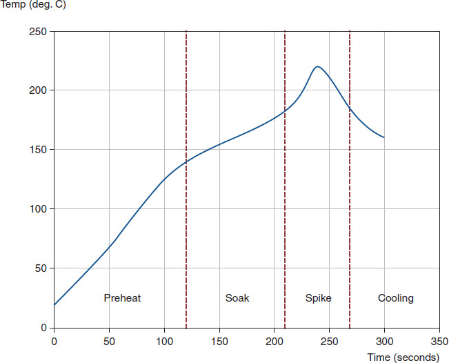
FIGURE 7-19 Leaded solder paste reflow profile.

FIGURE 7-20 Cooking the board.
Using a home-made device such as this will never be as reliable as using a professional oven, but it is fine for prototyping. Making one of these is dangerous and should only be undertaken if you really know what you are doing. You can find instructions for doing this at the following web pages:
• www.sparkfun.com/tutorials/60
• www.freetronics.com/pages/surface-mount-soldering-with-a-toaster-oven#.Us_cUGRdVyF
Both these tutorials describe how to manage the temperature by hand without the need for a complex controller. The final board is shown in Figure 7-21. You can see that the LED has moved a little. This is an effect of my cavalier application of solder paste but can be easily corrected with a little hand soldering.
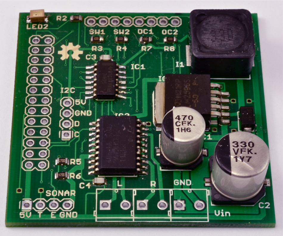
FIGURE 7-21 Final board.
Before you power up any board that you have made, you need to go over the whole thing very carefully with a magnifying glass to check that there are no accidental solder bridges and that all the pins are soldered to pads. Be especially careful around SMT ICs. You can mop up excess solder causing bridges using desoldering braid.
Depending on the solder paste that you used, you also may find little patches of flux and even tiny balls of solder on the board. I have a soft toothbrush that I use just to brush over the board. This will also highlight any loose components by brushing them off the board. This can be improved if you look for no-clean solder paste.
![]()
In this chapter we examined a few techniques for soldering components onto your PCB. Soldering is one of those skills that improves with practice, so never commit to too much on your first attempts. Start with something simple that you are prepared to throw away, and then work up. It is also not a bad idea to start with a simple soldering kit to get some practice.
In Chapter 8, we will follow an end-to-end example, designing and then building an Arduino shield.