Commands, Scripts, and User-Language Programs
Sometimes, when designing an electronic project in EAGLE, you will come across activities that are repetitive or that you seem to need to do for every project you start. It would be nice to be able to automate such activities and save yourself some time.
Fortunately for us, EAGLE includes technology to do just such automations. Scripts are simple lists of text commands to be invoked and are useful enough. However, EAGLE also includes a user-language program (ULP) language. This is a fully featured programming language that allows you to branch off and do different things under different circumstances or repeat certain instructions a number of times in a loop. For example, later we will look at how you can use a ULP to automatically smash all the parts on a schematic.
Ultimately, whether you use a ULP language or a simpler script, the end result will be the invocation of commands, and it is here that we will start.
![]()
You may have noticed the command line beneath the toolbars. You can type commands here that do the same things as you can otherwise accomplish using your mouse. Figure 10-1 shows a command ready to be run.

FIGURE 10-1 Entering commands.
Start a new project with a schematic, then enter the command add R-US_VMTA55@rcl (0 0.1), and then hit “Return.” You will see a resistor appear just above the origin. Let’s now examine this command.
The command is Add, and this can be specified in uppercase or lowercase—it doesn’t matter. You also can just use enough letters to make the command unique—in this case, just a would work fine.
The next section of the command line specifies what is to be added. In this case, it is the part R-US_VMTA55 in the library .rcl. Following this are the coordinates where the part is to be placed.
Let’s add another resistor just above the last one using the command
![]()
You should now have two resistors on the schematic, and you can delete them by typing the following commands:
![]()
All the commands on the Command toolbar have text equivalents that can be typed into the command line. You can find full documentation on all these in the built-in help accessible from the Help option on the Windows menu. Open the section called “Editor Commands.”
The command line is also available on the Board Editor. You also may have noticed the dropdown list on the right-hand side of the command line. This contains a list of previous commands used. When you select one of these, it will be copied into the command line, where you can edit it before running it. You also can access previous commands using the up-arrow on your keyboard.
Some people just prefer using the keyboard over a mouse and find this way of working natural, but the real power of these commands is in combining them into scripts and generating them from ULP languages.
![]()
A script is just a list of commands held in a text file that you can then run. EAGLE includes a set of script files that are ready to use. You will find them in the .scr folder in your EAGLE installation folder.
Let’s try out one of these scripts. The one you are going to try is called euro.scr. You can browse all the scripts in the “Scripts” section of the Control Panel. When you select one of the scripts in the list (Figure 10-2), a description of the script is displayed on the right-hand side of the Control Panel.
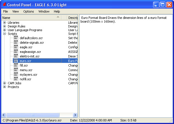
FIGURE 10-2 Selecting a script in the Control Panel.
If you double-click on the script in the Control Panel list, it will be opened in a text editor and will look something like this:
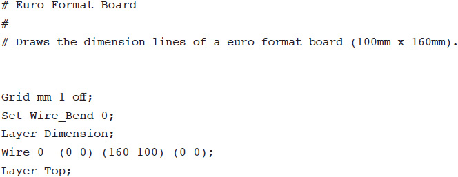
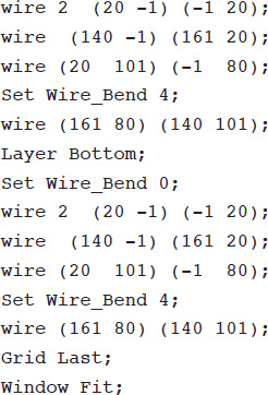
The three lines at the top starting with a # are just comment lines that explain what the script does. It is a script to be run in the Board Editor that creates a Euroboard. Euroboard is a standard size of board sometimes also called a Eurocard.
Switch to the board layout (creating one if needed) for your example project, and delete the existing wire rectangle in the “Dimension” layer. To run the command, click on the small “SCR” icon on the toolbar. This opens a dialog window from which you can select the script euro.scr. When it has run, the board should look something like Figure 10-3.

FIGURE 10-3 Creating the dimensions for a Eurocard.
If you have a section of design that you find yourself repeating often, then you could make yourself a script that adds all the parts and connects them up. For example, it is pretty common to use a 7805 voltage regulator and its accompanying capacitors in a circuit. You can write a script that will add the necessary components and then connect them up. This, of course, will take place in the Schematic Editor.
Probably the simplest way to do this is to enter the commands one at a time into the command line and then transfer them a line at a time into a Text Editor. Periodically, you can save the script file, delete everything off the schematic, and then continue adding commands until it does what you want.
To create a new script, select the option “New Script” from the File menu in the Control Panel, as shown in Figure 10-4.
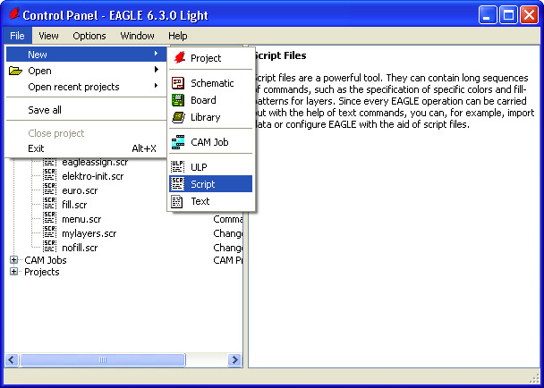
FIGURE 10-4 Creating a new script.
The logical place to start is with the 7805 itself. Wherever the assembly of voltage regulator and capacitors is built, it is likely to be in the wrong place. Thus it may as well be built over to the left, out of the way, so that we can move it into place afterward.
The command to create the 7805 is
![]()
You probably will have to explore the library doing a bit of wild-card searching to find the exact location of the component you need. Next, we need to add two capacitors, as recommended in the 7805 datasheet. Make a note of the positions for these capacitors by moving the cursor to where you want them to appear.
![]()
The values of these capacitors can be set using the following commands:
![]()
To add in the nets, we again have to find the coordinates of the end points and then use them in the following commands:
![]()
The module could do with symbols for GND and 5 V and then connect all these together with nets. Here are the commands for this:
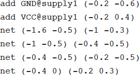
When it is all complete, the area of the schematic should look like Figure 10-5.
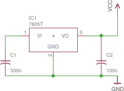
FIGURE 10-5 A 7805 regulator assembly generated by script.
Save the file in the .scr folder, and then you can use it by clicking the “SCR” button and selecting the script. You can download the script from the book’s webpage at www.simonmonk.org.
Scripts are great for simple automation tasks, but they are not able to do looping, branching, or other programming tasks. They also do not allow you to find out things about the schematic before performing some commands relating to the schematic. For example, you cannot select all the resistors and then change their values. To do these more advanced operations, you need to use ULPs.
![]()
The EAGLE ULP is a fully featured programming language with a C-like syntax. If you are used to programming, then you will soon get the hang of the syntax. It is beyond the scope of this book to teach programming in EAGLE ULP, but we will touch on the basics so that you can use the built-in ULPs and also understand a few basic techniques.
EAGLE has a collection of ready-to-use ULPs. These are accessed from a toolbar icon just next to the “SCR” button. This is labeled “ULP.” When you click it, you will be presented with a dialog from which to select the ULP that you want to run (Figure 10-6).
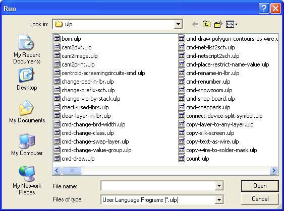
FIGURE 10-6 Running a ULP from the toolbar.
You can also access the ULPs from the EAGLE Control Panel (Figure 10-7), and if you are not sure which ULP you want to run, then this is a better place to do this because together with each ULP is a description of exactly what it does.
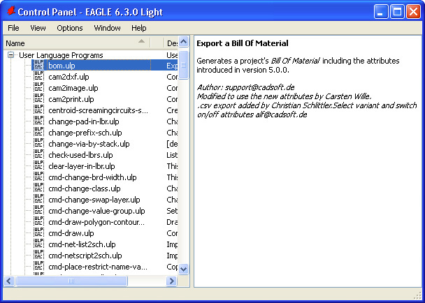
FIGURE 10-7 Running a ULP from the Control Panel.
These ULPs serve a wide variety of purposes. The ULP selected in Figure 10-8 will generate a bill of materials (BOM) from all the components in a schematic. It will create a separate file detailing all the parts you have used. To run it, right-click on the ULP name in the list, and select the option “Run in Schematic.” The window shown in Figure 10-8 will appear, listing all the parts used and giving you the option to save them in various different formats.

FIGURE 10-8 Running the BOM script.
Clearly, this is a long way from what is possible using simple scripts. Effectively, you can add your own features to EAGLE using ULPs.
Let’s take a look at one of the simpler ULPs (smash-all-sch.ulp). This useful ULP applies the Smash command to every part on a schematic. The code for this ULP is
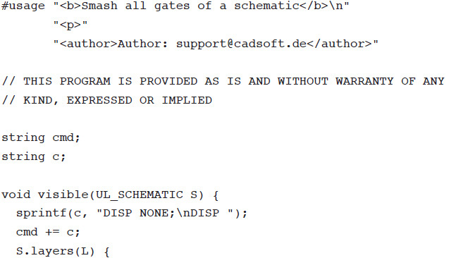
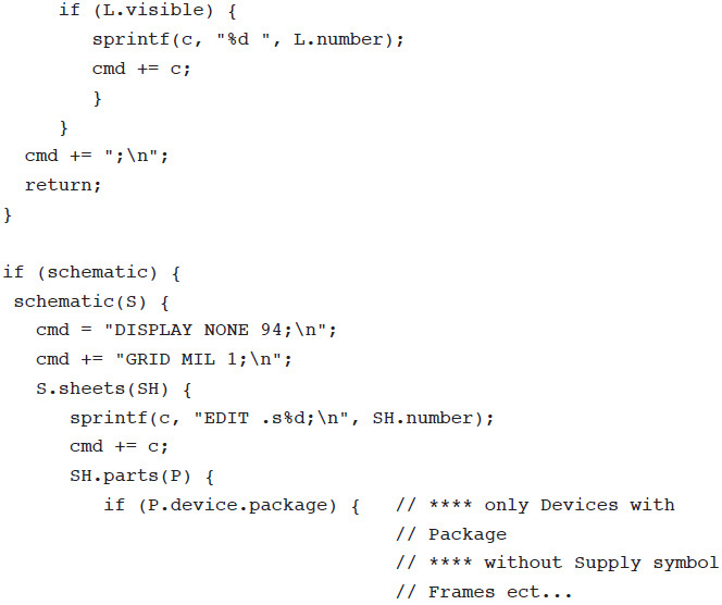
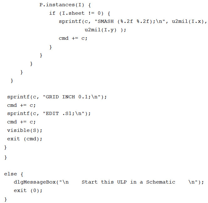
Starting at the top of the file, there is a # usage marker. The remainder of that line and the two lines that follow it specify the text that will appear in the Control Panel when you browse for ULPs. As well as plain text, this can also contain HTML; hence the <b> tag will make the first line bold.
Next, two strings are defined. The string cmd will eventually contain a whole script full of commands. These are not actually actioned by EAGLE until the following line of code near the end of the file is run:
![]()
In other words, the whole ULP builds up a big string of text that is then included in the Exit command that ends the execution of the script and also invokes the command string supplied.
The string c is used as a temporary working string whose contents will be built up and then appended to the main cmd string.
After the string declarations, there is a definition for a function (visible). This function will make the schematic visible and display all the relevant layers. It is called just before the script exits.
This ULP is designed to work on a schematic, and the ULP includes a test to make sure that the window from which the ULP has been invoked is actually a schematic. You will find this in the following line, halfway down the program:
![]()
If you mentally close off the braces to find the else condition for this, you will find the following lines right at the end of the file:

This displays a dialog window telling you that you are not in a schematic window.
Assuming that the ULP is being run in a schematic window, we now have a chunk of code that iterates over the schematic in a hierarchical way constructing the command to be run. This uses a syntax that names an object in the design’s internal model and then a variable that can be used to access all instances of such objects. For example,

All the code inside the curly braces will be repeated for each schematic, and the schematic whose turn it is can itself be accessed using the variable S. There is only one schematic, so this syntax makes more sense if we look a bit further down the program, where every sheet of a schematic is iterated over and then within that every part on every sheet using
![]()
![]()
In this chapter we have looked at using scripts and ULPs to automate activities in EAGLE. The EAGLE ULP manual is some 130 pages long, so we have only really scratched the surface of the language. You can find out more about it at ftp://ftp.cadsoft.de/eagle/userfiles/doc/ulp_en.pdf. You will also find a reference for ULP in Appendix C.
In Chapter 11, we will return to libraries and learn how to modify and create our own libraries and parts.