Creating Libraries and Parts
Experienced EAGLE users often find it useful to start building their own library of components that they use frequently. This chapter shows you how to do this and how to copy and modify components from other libraries.
It is easier to copy and modify an existing component than to create a new one entirely from scratch, so we will develop an example where we modify the pad positioning of a part.
![]()
Parts libraries are each held as a single file with the extension .lbr in the lbr folder within the EAGLE installation directory. New libraries can be added simply by copying .lbr files into this directory. In fact, we did this back in Chapter 1 when we installed the Adafruit and Sparkfun libraries. Component manufacturers and suppliers often have their own libraries of components. Another similar library is available from Seeedstudio (www.seeedstudio.com).
However, in this case, you are going to create your own library from scratch. We will give it a general name, and if you do this, you probably will find it to be a useful place to keep modified or new parts that you create.
To create a new library, open the Control Panel window of EAGLE, and then from the File menu, select the option to create a new library (Figure 11-1).
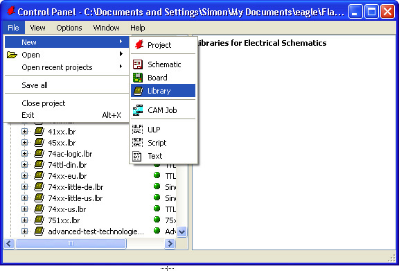
FIGURE 11-1 Creating a new library.
This will open a new untitled Library Editor window. The first thing you should do is save this using the Save command from the File menu with the Library Editor as the current window. You will be prompted for the name of a file. Call it
![]()
![]()
Later we will look at building a device (part) from scratch, but to start with, we will copy an existing part from another library into our new library. Later we will edit this device.
Copying a part is not quite as simple as selecting a part, doing Copy, moving to the library where you want to have a copy of it, and doing Paste. Instead, EAGLE has the concept of a current library. Because we have just created a new library, this will be the current library. To copy the part into the current library (“MyParts”), we first need to go and find the part that we want to copy in the “Libraries” section of the Control Panel.
The first part we are going to copy is the LED display module that we used back in Chapter 8. You may remember that this had some mislabeled pins. You will find this part in the Sparkfun “Displays” library, where it is called 7-SEGMENT-4DIGIT-YOUNGSUN. Right-click on it, and select the option “Copy to Library” (Figure 11-2).

FIGURE 11-2 Copying a part.
As soon as you do this, the part will appear in the Part Editor window (Figure 11-3).
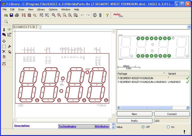
FIGURE 11-3 The Part Editor window.
Let’s take a quick tour of the Part Editor window. The large editor area shows the schematic view of the part (its symbol). To the bottom right, there is a list of packages available for this symbol. This is showing two entries, one normal and one with long pads. Above this is the package as it would appear on the board layout.
You will notice that over on the left of the editor we have a Command toolbar that operates on the same principal as the Schematic and Board Editors but with a smaller set of commands available.
![]()
Before we start modifying this part, we need to understand a bit more about how parts are organized in an EAGLE library. A device has a symbol (this is shown in the schematic); it also has one or more packages. These will appear on the board layout. The part as a whole is represented as a device. The device links together the symbol and the packages, as well as specifying the relationship between the pins on a symbol and the pads on a package.
Symbols and packages are created independently and linked together by devices, allowing the same package design to be used by a number of different symbols.
In Figure 11-3, the Part Editor is showing the device. This same editor window is also used when you want to edit the symbol or one of the packages of the device. You will notice three new icons on the toolbar to the right of the “Printer” icon that allow you to select the element of the device that you want to edit.
![]()
We need to fix the labels on this part because the anode and cathode of the colon and apostrophe of the display are swapped over. You may be wondering if this is a change to the pad names or to the symbol. Well, the pad names are just named 1 to 16 on both packages, so the change needs to be made in the linkage between the pin names on the symbol and the pad names. This takes place for each package of the device. So let’s start with the package 7-SEGMENT-4DIGIT-YOUNGSUN. Select this in the list of packages, and then click the “Connect” button. This will open the window shown in Figure 11-4.

FIGURE 11-4 Editing connections.
The rightmost of the three columns shows the current linkages between pins and pads for that package. In this case, you can see that APOS-A is linked to pad 10 and APOS-C is linked to pad 9. These need swapping over, as do the associations between COL-A (pad 4) and COL-C (pad 12). To sort this out, we first need to disconnect these four connections. To do this, select each in turn, and click “Disconnect.” This will have the effect of moving both the pins and the pads concerned into the first two columns, as shown in Figure 11-5.
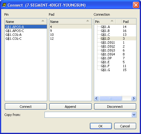
FIGURE 11-5 Rearranging pads and pins.
We now need to remake these links, but this time linking
• APOS-A to pad 9
• APOS-C to pad 10
• COL-A to pad 12
• COL-C to pad 4
This is done by selecting one pin from the first column and one pad from the second column and then clicking “Connect.” So click APOS-A and pad 9 and click “Connect.” Repeat for the other three links above. When everything is connected, the Connection editor should look like Figure 11-6, with everything back in the right-hand column.
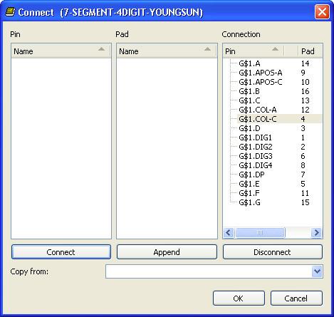
FIGURE 11-6 The connections amended.
Finally, repeat this for the other package in the device, and then save the device from the File menu.
![]()
To really get to grips with the Part Editor, we are now going to add a completely new device to our library. The device we are going to add is shown in Figure 11-7.
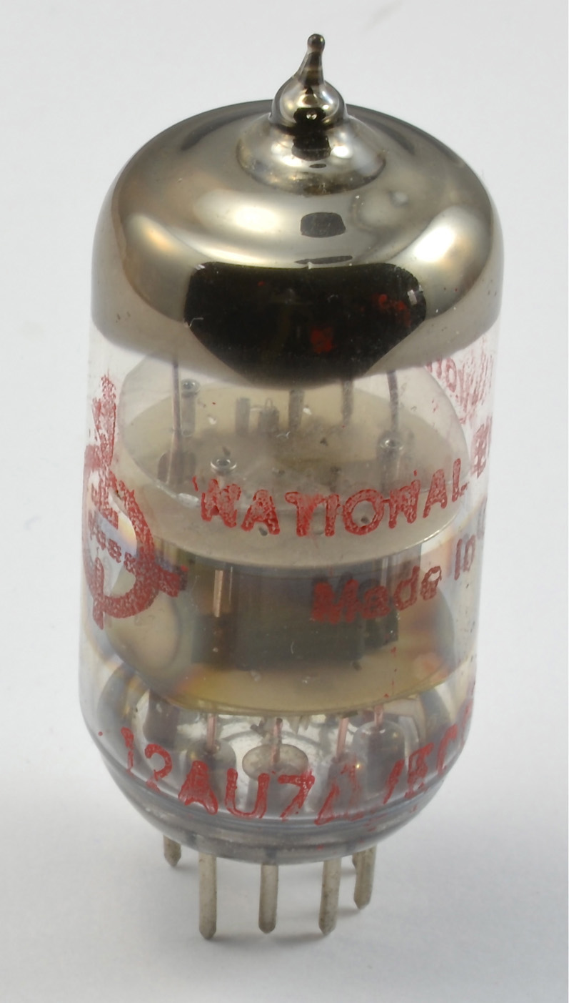
FIGURE 11-7 A 12AU7 triode tube.
This device is a vacuum tube (a double triode). The vacuum tube is a device largely made redundant by transistors and integrated circuits (ICs) but retaining a niche role in audio amplifier design, where it is used by audiophiles for the low-frequency even harmonic distortion that many people find gives an attractive color to music.
It is not a total surprise that this device is not currently included in the libraries that ship with EAGLE, so we will make our own part for it, especially because I intend to make myself a preamp using this device and would like to design the PCB using EAGLE.
You can find the datasheet for this tube at www.wooaudio.com/docs/tube_data/12AU7.pdf.
The steps involved in making this part will be
1. Make the package.
2. Make the symbol.
3. Make the device to link the two together.
If it is not already open, then open your “MyParts” library. To create a new package, you need to click on the “Packages” icon on the toolbar. This will open a window that shows the packages that we copied for the LED display (Figure 11-8). In the field labeled “New,” enter the name RETMA-9A. This is the name given to the package on the tube’s datasheet. Hit the “Enter” key, and the Part Editor window will open on a new file called RETMA-9A.pac. We will use this editor to create the package.

FIGURE 11-8 Creating a new package.
The package footprint consists of nine pads arranged around a circle with a diameter of 0.5 in. The pads are spaced out as if there are 10 pins but with one of the pads missing. A good technique is therefore to draw a circle (that we can later delete) of diameter 0.5 in. and then position the pads around it.
It does not really matter what layer we draw the circle on because we are going to delete it later, but in this case, it is on “tPlace.” Because there are effectively 10 pin positions, each pin will be 360/10 = 36 degrees from the next pin around the center of the package. If you use the Mark tool and mark the origin of the package, then as well as showing the X and Y coordinates of the cursor relative to the center of the circle, it will also show the polar coordinates, that is, the distance from the center and the angle. We can use this to position the pads at 0, 36, 72, and so on degrees around the circle (Figure 11-9). To do this, use the Pad command from the Command toolbar. You can change the diameter and drill to match the tube socket that you are going to use before adding the pads. You will need to set the grid to be, say, 0.001 in. in order to position the pads accurately.
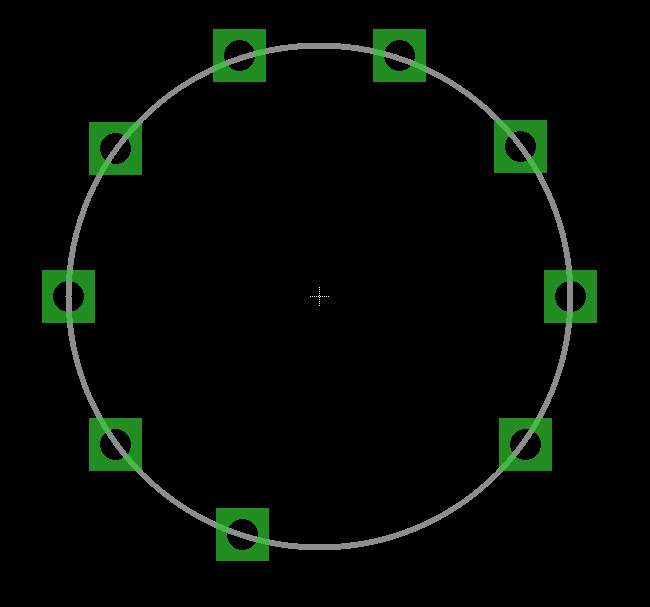
FIGURE 11-9 Positioning pads.
The tube itself has a diameter of about 0.75 in., so let’s mark that footprint by drawing a circle with that diameter in place of the 0.5-in. circle, which we can now delete. Note that you probably will want to reset the grid to 0.025 in.
The next step is to name all the pads. We are just going to name these sequentially from 1 to 9 clockwise around the package. We now need to add two pieces of text onto the package “>Name” and “Value.” The text “>Name” should be placed on the “tNames” layer and “Value” on the “tValues” layer. Once all this is complete, the package should look something like Figure 11-10. Don’t forget to save it.
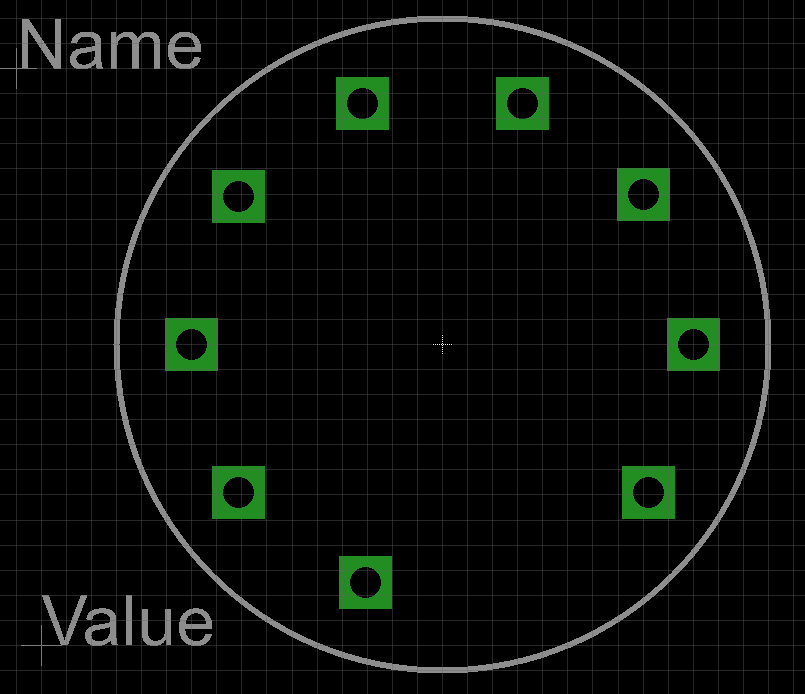
FIGURE 11-10 The completed package.
To make the symbol for the device, we are going to carry out a similar process to making the package. However, one key difference is that this tube is a dual triode; that is, it is a single glass envelope containing two triodes. We therefore only need to create the symbol for one triode, and we will see later how these can be added twice to the device as gates. But first, let’s draw the symbol.
Create a new symbol called TRIODE by clicking on the “Symbol” icon and then typing the name TRIODE in the “New” field and hitting the “Enter” key. This will display a blank editor window for us to use on the file TRIODE.symq. The circuit symbol for a triode is a circle containing what are in essence three horizontal lines from top to bottom, the plate, grid, and cathode. The grid is a dashed line, and the cathode has turned-over corners. In any case, it is pretty easy to draw.
The size is pretty arbitrary, but I am going to make the symbol about ¾ in. wide because these will be the central components of the amplifier that I intend to build. Draw the symbol on the “94 Symbols” layer using the Circle and Wire commands. I used a wire width of 0.32 in. There also need to be wires of 0.01 in. from each of the three lines out to the edge of the circle. Figure 11-11 shows the remainder of the “Symbol” layer drawing.
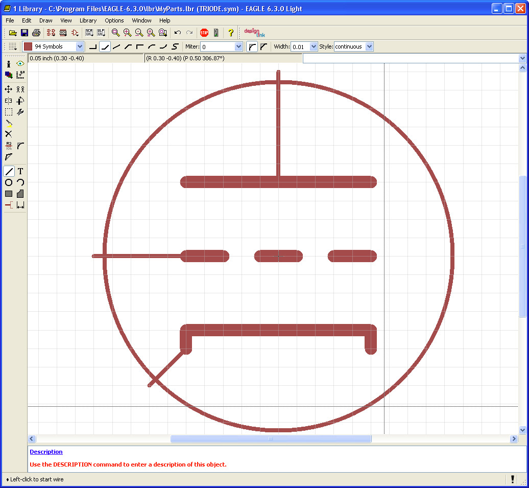
FIGURE 11-11 Drawing the triode symbol.
Just as we had to add pads to the package, we now have to add pins to the symbol. Select the Pin command, and then select a style of pin from the toolbar that does not include a line attached to the pin. That is, select a style that is a simple circle (“Point”). The pins will need renaming and their direction type setting. The most convenient way of changing this for each pin is to use the Information tool.
Starting with the pin you added at the top of the symbol, select the Information command, and then click on the pin. Then change the name of the pin to PLATE, the direction to pass, and “Visible” to off, as shown in Figure 11-12.
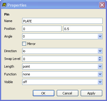
FIGURE 11-12 Changing a pin.
The various directions allowed for a pin are used by the electrical result checker (ERC). Thus, for example, it will flag outputs being connected together on a logic gate. In this case, we are specifying that the pin is electrically speaking passive (pass). This isn’t really true, but selecting this option will prevent any false warnings from the ERC. Repeat this process for the GRID and CATHODE pins.
You will have noticed an area at the bottom of the parts window suggesting that you Use the DESCRIPTION command to enter a description of this object. To do this, click on the “Description” hyperlink immediately above that message. This will enter a new window into which you can enter a description of the symbol.
In addition to the two triodes, the tube also has three connections used to provide power to the heater element, one of the connections being a center tap. We therefore need to bring the three “power” pins that we can collect together into a third symbol. Even though there are two triodes in the glass tube, they have shared connections for the heater power.
Create a new symbol, and call it HEATER_SUPPLY. Place three pins on the design, and change their names to “HA,” “HC,” and “HB” (heater A, B, and common). Pick a pin style with a bit of a tail on it. The end result of this is shown in Figure 11-13.
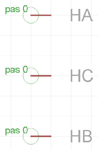
FIGURE 11-13 Creating a heater supply symbol.
We have a package and a symbol for our valve, but we have not linked the two or let EAGLE know that the package actually contains two triode symbols. To do this, we need to create a device by clicking on the “Devices” icon in the toolbar and then entering the name 12AU7 into the “New” text field. In the view that then appears, we need to use the Add tool to add two of the TRIODE symbols and one HEATER_SUPPLY symbol to the main editor area.
Next, we need to add the package, so, in the bottom right of the Editor Window, click on the “New” button, and select “RETMA-9A.” The editor window should now look like Figure 11-14.
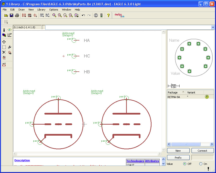
FIGURE 11-14 The device with symbols and package.
There is still no link between the pins on the symbols and the pads on the package, so let’s make those connections by clicking on the “Connect” button. After matching the pairs up using the datasheet, it will look like Figure 11-15.

FIGURE 11-15 Making connections from pins to pads.
Our part is now complete. Don’t forget to save it. You can try adding it to a schematic. Remember that because the device has a number of gates, the first two times that you add it to the schematic, it will add a triode symbol, and the third time it will add the heater supply symbol. You can also switch over to make sure that the board layout looks okay too. Figure 11-16 shows the device as used in a schematic.
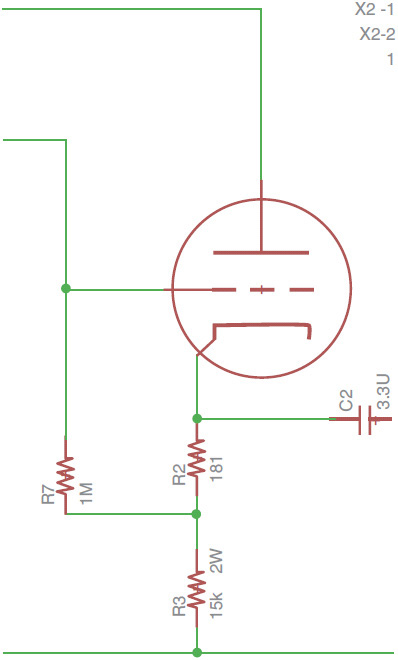
FIGURE 11-16 Using the new device.
If you want to share the library containing the part, you can simply pass on the “MyParts” library file that you will find in the lbr folder in your EAGLE installation directory. Note that if you are planning on sharing the part, you might want to give it a more specific name.
![]()
In this chapter, you have discovered how to create your own library, to which you can either add modified packages, symbols, and devices or create your own parts from scratch. Before creating a new part, it is always worth an Internet search to see if someone else has already made that part. Some component suppliers also provide an EAGLE library for their products.