CHAPTER 8
STANDING WAVES AND WAVE SUPERPOSITION
With the music of stringed instruments and with melody on the harp, because of what you have done, I sing for joy. —PSALMS 92:3–4
It is ironic that Columbus never knew that he had discovered a new continent; he firmly believed what he found was a new route to India. The task of naming the new continent and exploring the land was done incrementally by many others over the subsequent five hundred years. Prigogine was arguably much luckier in knowing he had discovered a new realm and witnessing the explorations of others in the new territory.
Standing Waves Are Dissipative Structures
The conventional standing wave, described in chapter 3 and known in physics for hundreds of years, is also a kind of dissipative structure. Understanding how these waves work and some of their properties is key to comprehending how acupuncture can influence the dissipative structure in the body.
The first image in figure 8.1 depicts a simple example of a standing wave on a string. It resembles three spindles placed head to tail. These are not solid structures, like real spindles, but dynamic structures. The more precisely a standing wave is observed, the more apparent its instability becomes. This is especially true for relatively high frequencies.
The energy supporting the dynamic structure is provided by a small motor that keeps the string in permanent vibration, as shown in the second image. The standing wave also constantly dissipates energy, mostly in the form of acoustic waves. The length of the string determines the frequency of the standing wave, shown in figure 8.2, which in turn determines the frequencies of the related acoustic waves emitted by the string. All stringed musical instruments function according to this working principle.

Figure 8.1. Standing wave in a string (top) and the energy supplied by a motor (bottom).

Figure 8.2. The fundamental frequency (f1) and the frequencies of the overtones (f2, f3, f4) are determined by the length of the string.
In musical instruments, the length of the string is controlled by the fingers of the musician. Constantly changing finger positions allows the musician to establish standing waves of desired frequencies at specific times, thereby producing the melody. In most cases, several different frequencies exist together on the same string, as shown in figure 8.2. The lowest frequency, f1, is called the fundamental frequency and is usually the one written in the score, indicated by the note. In musical terms, the frequencies f2, f3, and f4 are referred to as overtones. Different musical instruments produce varying combinations of strengths of individual overtones. This creates what is known as the timbre or tone color of an instrument, and distinguishes the sound of one violin from another, or a violin from a guitar.
The working principle of wind instruments is also based on the regulation of standing waves. The tube of a wind instrument provides a resonance cavity in which there are invisible standing waves of varying air pressure. The frequencies of these standing waves are determined by the length of the tube. By altering finger placement to alternatively open and close holes in the tube, the musician changes the effective length of the tube. This modifies the frequency of the standing waves inside the tube, thereby changing the note emitted by the instrument.
The frequencies of standing waves in percussion instruments are dictated by the size of the instrument. As it is not easy to change the size of the resonance cavity in a percussion instrument, performers usually use a series of percussion instruments that correspond to various notes to play music.
Superposition of Standing Waves
As mentioned earlier, waves possess another interesting feature: unlike particles, two or more waves can simultaneously occupy the same space, combine together to form a single new wave, or even cancel out one another completely, vanishing into nothing. In other words, they can superimpose. In the terminology of physics, they interfere with one another, thereby forming a new interference wave. As such, physicists refer to the phenomenon as interference.
Superposition of Two Waves
First, let us consider what happens when two waves, with the same wavelength and the same phase—their peaks and troughs occurring at the same time and place—occupy the same place. Figure 8.3 demonstrates the outcome; a new wave is created with a larger amplitude (height). The amplitude of the new wave is equal to the sum of the two original amplitudes.
It is not difficult to visualize and understand this addition operation in the procedure of superposition. It is, however, somewhat unusual that the arithmetic in the world of waves is 1 + 1 = 1, at odds with the ordinary arithmetic of 1 + 1 = 2 in the world of particles. In a way, it is like two people sitting on a couch together becoming a new person of double size.

Figure 8.3. Superposition of two waves in the same phase: constructive interference.
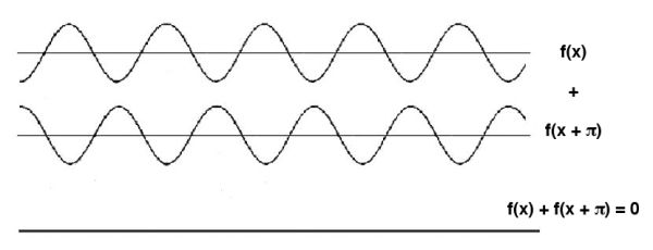
Figure 8.4. Superposition of two waves with phase difference of half a cycle: destructive interference.
When two waves with opposite phases are superimposed in the language of mathematics, the two waves have 1π (180° or half a cycle) phase difference, or to put it more simply, when one wave is at a peak, the other wave is at a trough. The outcome of the superposition is known as destructive interference, and the new wave has zero amplitude. The peaks of the first wave coincide with the valleys of the other wave, cancelling each other out. This is the working mechanism behind noise-canceling headphones and other forms of active noise reduction. In this case, the arithmetic is even more unusual: 1 + 1 = 0. It seems that the two people sitting together on a couch disappear.
In terms of physics, the first case (fig. 8.3) is called constructive interference because the outcome is greater than the two original waves. The second scenario (fig. 8.4) is called destructive interference because the outcome is smaller than the two original waves. These examples are the extremes; in reality, most cases of superposition and interference occur somewhere between them. Examples include figure 3.5 in chapter 3, which shows the classic double-slit experiment—two light beams may enhance each other, creating brighter regions (constructive interference), or cancel each other, producing darker regions (destructive interference). Figure 3.4 shows what happens when two waves of different wavelengths interact—a new frequency, called a beat frequency, is generated by the superposition.
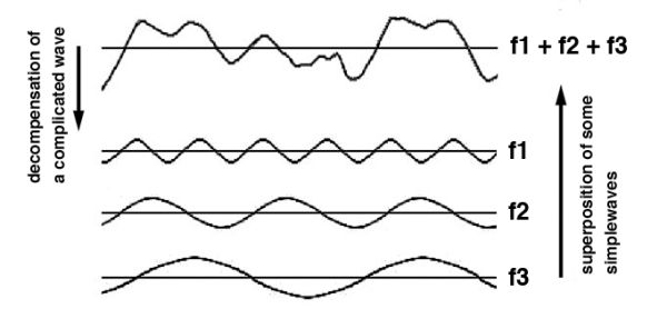
Figure 8.5. A complicated curve from the superposition of three waves.

Figure 8.6. Comparison of the curve from electronic measurement on the human body and the curve created by superposition of three waves.
Superposition of Many Waves
The process of superposition is not limited to two waves; any number of waves can interact, as in figure 8.5. By superimposing a number of simple waves, it is possible to create any number of periodic curves, which are a continuous repetition of the same shape, as in the beat frequency in figure 3.4, or even aperiodic waves, at the top in fig. 8.5.
In light of this understanding, it is useful to revisit the background of electronic measurements on the skin. As explained in chapter 6, these measurements actually reflect the distribution of energy inside the body. Figure 8.6 allows for comparison between the curve in electronic measurements on the human body (top in fig. 8.6), and the curve generated by the superposition of three waves (bottom in fig. 8.6). This makes it easier to visualize how a heterogeneous distribution of the electromagnetic field could be generated by the superposition of electromagnetic waves. In reality, the complexity of the human body and the multitude of electromagnetic wave emitters in it result in much more complexity than the simplified conditions in figure 8.5.

Figure 8.7. Interference pattern and calculations for two two-dimensional circular waves.
Two-Dimensional and Three-Dimensional Standing Wave Interference
The preceding discussion only considered superposition and interference of waves and standing waves in one dimension. In reality, most situations involve waves in two or three dimensions. In theory it is possible to calculate interference patterns in two- and three-dimensional cases (fig. 8.7). Practically, however, even with powerful computers, these calculations are usually a mammoth undertaking. Fortunately, the work required to observe interference patterns in two dimensions is not overly complicated. In chapter 3, figure 3.7 depicts interference patterns of standing waves in a vibrating disk, and in figure 3.8, inside a violin.
Modulation of the Interference Pattern
Once it is established that the subtle energy distribution inside the body is mostly determined by the superposition of electromagnetic waves, that is, the energy distribution is in fact an interference pattern, a method of modulating it becomes apparent. An unhealthy energy distribution inside the body of a patient can be improved by intentionally introducing a disturbance into the interference pattern. This can alter the energy distribution, thereby allowing the patient’s health to improve.
Changing Frequencies
Medical doctors in Western countries have already invented numerous methods of introducing electric stimulation to a patient’s body to assist in regaining health. While these doctors were unaware that this stimulation would alter the patient’s energy distribution, they were comfortable with the term energy medicine. They believed they had detected some pathogenic bioelectricity in patients. As such, they thought they could cancel it out by introducing external electrical stimulation.
These pioneers ventured beyond the chemical aspect of the body into the energetic aspect of medicine, an important step forward that contributed greatly to the development of medicine. Unfortunately, these methods and their inherent way of thinking are still limited by the framework of Western medicine and reductionism. If the effect of electrical stimulation on the existing interference pattern of electromagnetic standing waves in the body were better known, it would be understood that the treatment is holistic. Moving toward a better understanding of the source of the heterogeneous energy distribution in the body will inevitably lead to significant developments in energy medicine.
Changing the Boundary Condition of a Resonance Cavity
In addition to introducing external electrical or magnetic stimulation, the interference pattern of electromagnetic waves in the body—the energy distribution—can also be modulated by changing the boundary conditions of the resonance cavity. As is evident in figure 3.8 in chapter 3, the shape of the interference pattern of standing waves produced inside a violin is not solely determined by the frequency of stimulation, but also by the shape of the cavity.
To further illustrate, consider interference patterns of standing waves on the surface of water (plate 11 in color plate section) created by placing a loudspeaker beneath a pan of water. When the loudspeaker emits a constant sound signal, a stable interference pattern appears. At left, a ring appears in the water. At right, three smaller rings of varying diameter have been introduced instead. In both cases, the frequency of the sound signal was the same. The interference pattern was greatly modified by means of simple change in the boundary conditions.
Significant changes in interference patterns do not require major changes in boundary conditions. Sometimes a tiny change can greatly alter the interference pattern and related frequencies that form standing waves. For example, it is well established that a small slit will greatly damage the sound of a musical instrument.
Physicist Hans-Jürgen Stöckmann, from Marburg University in Germany, conducted both experimental research and theoretical calculations concerning the change of standing waves on a rectangular shape. His results show that even a tiny hole in the shape greatly changes the interference patterns that arise (fig. 8.9).1 In order to get the most pronounced changes in the interference pattern, specific points need to be chosen to make the holes. The best places are in regions where the energy of the original interference pattern is highest. This provides insight into why acupuncturists always insert their needles at locations with lowest skin resistance and call these sites acu-points. The locations exhibiting the lowest readings for skin resistance are actually the places of highest energy, determined by the interference pattern of the standing electromagnetic waves within the body, which is a dissipative structure of the electromagnetic field inside the body.

Figure 8.9. Interference pattern in a rectangular plate (a) without a hole and (b) with a hole (the white dot).
Figure 8.10 is a simplified one-dimensional example to illustrate how an acupuncture needle may work. Suppose the electromagnetic waves being emitted by an ailing organ have altered from their original frequency to an inappropriate one. In turn, this wave has generated a detrimental standing wave. Inserting a needle at the acu-point establishes a new boundary condition at one of the peaks of the electromagnetic standing wave. As the best place to insert a needle to cancel a standing wave is at any peak, this will serve to cancel the inappropriate standing wave. As a result, the unwell organ will be positively influenced, helping it return to its optimal frequency.
Of course, real conditions are far more complicated than the idealized situation in figure 8.10. There are multitudes of standing waves in the body that form a complex interrelated three-dimensional interference pattern. Consequently, inserting a needle into a point of high-energy intensity in the body introduces a major disturbance to the entire interference pattern.
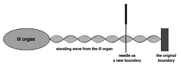
Figure 8.10. A possible working mechanism for the effect of needling.
The change in interference pattern during acupuncture, or any other disturbance, can be monitored by attaching a probe matrix to the skin. The results can then be intelligibly expressed using pseudo-colors on a computer display (plates 11 and 12 in the color plate section). The images show how the interference pattern in the arm changes over the time that a needle remains in an acu-point. This experiment also demonstrates that if the needling operation is successful, it generally takes between ten and twenty minutes for an interference pattern to change from its initial stable state to a new stable state. This period is consistent with the duration of acupuncture treatment sessions.
The slow pace of the preceding change in the interference pattern is of special importance. As discussed in chapter 5, physicist Bi-wu Zhang pointed out in 1959, long before the discovery of dissipative structures, that the notably slow speed of sensation propagation along meridians, in contrast to the extremely high speed of individual electromagnetic waves, could come from the grouping speed of many electromagnetic waves. The situation depicted in figure 8.11 involves the interactions of billions and billions of electromagnetic waves. As such, the speed of signal progression becomes so slow, even for the small area being monitored, that it takes twenty minutes for the change in the interference pattern to complete.