Objective 5.1—Create and Administer Logical Switches
This chapter covers all or part of the following VCP6-NV exam blueprint topics:
Objective 5.1—Create and Administer Logical Switches
Chapter 5, “NSX Switches,” discussed what a logical switch and universal logical switch are but didn’t quite visualize how traffic is sent between virtual machines (VMs) in the same VNI. This chapter does packet walks for multiple scenarios of VMs in the same logical switch communicating with each other. This chapter also covers the different cases of what the logical switch and universal logical switch do when they receive a broadcast, unknown unicast, and multicast (BUM).
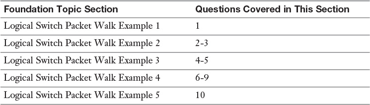
The “Do I Know This Already?” quiz allows you to assess whether you should read this entire chapter or simply jump to the “Exam Preparation Tasks” section for review. If you are in doubt, read the entire chapter. Table 6-1 outlines the major headings in this chapter and the corresponding “Do I Know This Already?” quiz questions. You can find the answers in Appendix A, “Answers to the ‘Do I Know This Already?’ Quizzes.”
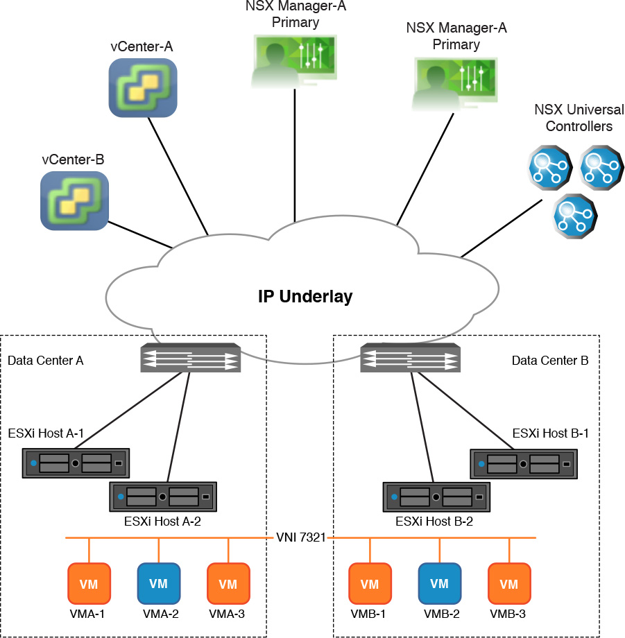
Use the following information to answer the questions that follow. In Figure 6-1, Host A-1 and Host A-2 are part of the same cluster in Data Center A managed by vCenter-A and paired with NSX Manager-A. Host B-1 and Host B-2 are part of the same cluster in Data Center B managed by vCenter-B and paired with NSX Manager-B. NSX is configured for cross vCenter NSX. NSX Manager-A is the Primary NSX Manager and NSX Manager-B is a Secondary NSX Manager. VMA-1 and VMA-2 are running in Host A-1. VMA-3 is running in Host A-2. VMB-1 and VMB-2 are running in Host B-1. VMB-3 is running in Host B-2. All VMs are connected to Universal Logical Switch 7321.
Figure 6-1 Reference diagram for “Do I Know This Already?” quiz
1. VMA-1 sends traffic to VMA-2. Based on the diagram, how does the logical switch in ESXi Host A-1 know to forward the frame to VMA-2?
a. The logical switch in Host A-1 will have the MAC address for VMA-2 in its MAC table since it was provided by the NSX Universal Controller.
b. The logical switch in Host A-1 will have the MAC address for VMA-2 in its MAC table because it copied it from the vmx file.
c. The logical switch in Host A-1 will have the MAC address for VMA-2 in its MAC table because it was provided by the NSX Manager.
d. The logical switch in Host A-1 will not know where to forward the frame and will therefore broadcast it.
2. VMA-1 sends traffic to VMA-2. The logical switch in ESXi Host A-1 does not have an entry for VMA-1’s MAC address in the MAC table. Based on the diagram, what could be the reason for this?
a. The NSX VXLAN module in Host A-1 is disabled.
b. The NSX Universal Controller can’t communicate with Host A-1.
c. VMA-1’s guest OS is forging its MAC address.
d. VMA-1 is booting up.
3. The logical switch in Host B-2 learns a MAC address from one of its VMs. Based on the diagram, what action is then taken by the logical switch?
a. The logical switch in Host B-2 adds the MAC address to its MAC table and informs the Switch Security module in Host B-2 so the ARP table can be updated.
b. The logical switch in Host B-2 tells all the NSX Universal Controllers about the MAC address.
c. If the resulting size of the logical switch in Host B-2’s MAC table is bigger than the NSX Universal Controllers MAC table, Host B-1 becomes the keeper of the principal MAC table for VNI 7321.
d. The logical switch in Host B-2 will learn the MAC address and send an update to the NSX Universal Controller responsible for the logical switch.
4. The Top of Rack (ToR) switch receives a VXLAN frame from Host B-1. The frame is transporting traffic from VMB-2 destined for VMA-3. Based on the diagram, what two actions does the ToR switch take? (Choose two.)
a. The ToR learns the MAC address of Host B-1’s VTEP.
b. The ToR learns the MAC address of VMB-2.
c. If the destination MAC address is the MAC of Host A-2’s VTEP and the ToR does not know the MAC address of Host A-2 VTEP, it will broadcast the VXLAN frame.
d. If the VXLAN frame’s destination MAC address is a unicast and it is not the MAC address of Host A-2 VTEP, the switch will not send a copy of the frame to Host A-2 VTEP.
5. Based on the diagram, if all the VTEPs of the ESXi hosts in the Data Center B cluster are in the same VLAN, the same subnet, and connected to the same ToR, which statement is true?
a. Spanning Tree must be configured in the ToR on all ports connected to the ESXi hosts.
b. A default gateway must be configured for the VTEPs to communicate with each other.
c. The ToR switch never learns the MAC address of the virtual machines.
d. The VTEPs can’t communicate with each other because they are in the same Ethernet broadcast domain.
6. Based on the diagram, if all the VTEPs of the ESXi hosts in Data Center A are in the same VTEP subnet, which Replication Mode causes the VTEPs to send the least amount of replication frames?
a. Hybrid
b. Unicast
c. Broadcast
d. Directional
7. Based on the diagram, if Host B-1 is the MTEP, what replication mode has been configured for the logical switch?
a. Broadcast
b. Multicast
c. Unicast
d. Hybrid
8. Based on the diagram, if no Host has selected an MTEP or UTEP for Universal Logical Switch 7321, what is the Replication Mode for logical switch 7321?
a. Broadcast
b. Multicast
c. Unicast
d. Hybrid
9. Logical switch 7321 in Host B-2 receives an ARP reply from VMB-2. Based on the diagram, what two actions will the logical switch take with regards to the frame? (Choose two.)
a. It will broadcast the frame to VMA-3.
b. It will unicast the frame to VMA-3.
c. It will send the frame to the Switch Security module to add it to the ARP table.
d. It will reset the dead timer to five minutes if VMB-2’s MAC address is in its MAC table.
10. VMB-3 vMotions to Host B-1. Based on the diagram, what does Host B-2 do after the vMotion migration is completed?
a. The Universal NSX Controller tells Host B-1 the MAC address of VMB-3.
b. Host B-2 tells the NSX Universal Controller to remove it from the VTEP table.
c. Host B-2 tells the NSX Universal Controller that Host B-1 has the MAC address of VMB-3.
d. Host B-2 sends an RARP to all other hosts to let them know VMB-3 is now in Host B-1.
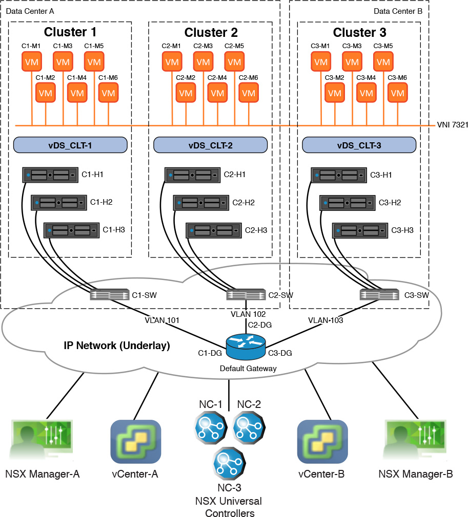
This section reviews multiple packet walks involving communications between VMs connected to the same Ethernet broadcast domain. Each packet walk shows a different aspect of the process the logical switches follow to deliver a frame to its destination. All packet walks reference Figure 6-2 or a derivative thereof, with some figures including different step numbers relevant to the packet walk. Each packet walk uses Universal Logical Switch 7321 as the broadcast domain. The packet walk steps would be the same if you used a logical switch instead of a universal logical switch. Thus I interchange logical switch and universal logical switch through the packet walks as well as NSX Universal Controllers and NSX Controllers.
Figure 6-2 has three sets of ESXi clusters, all configured to support NSX.
vCenter-A is paired with NSX Manager-A, which is the Primary NSX Manager in the cross vCenter NSX domain.
vCenter-B is paired with NSX Manager-B, which is a Secondary NSX Manager in the cross vCenter NSX domain.
Both data centers share a common Layer 3 physical router (named Default Gateway in Figure 6-2).
Cluster 1 and Cluster 2 are in Data Center A. Cluster 3 is in Data Center B.
Each ESXi cluster has its own vDS, which is also used for the portgroups backing the logical switches.
Each ESXi cluster has three ESXi hosts.
Each ESXi host has two powered on virtual machines.
There are three NSX Universal Controllers.
Each ESXi host has IP connectivity via the Management VMkernel port to all NSX Universal Controllers, its corresponding NSX Manager, and vCenter.
Each ESXi host has a single VTEP.
Each ESXi host is shown with a single VMNIC to the physical network.
ESXi host Management, vMotion, IP storage, and VXLAN encapsulated traffic will traverse this interface.
ESXi host Management traffic will use VLAN 10.
vMotion traffic will use VLAN 20.
IP Storage traffic will use VLAN 30.
Cluster-1 VXLAN encapsulated traffic will use VLAN 101.
Cluster-2 VXLAN encapsulated traffic will use VLAN 102.
Cluster-3 VXLAN encapsulated traffic will use VLAN 103.
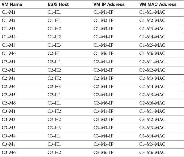
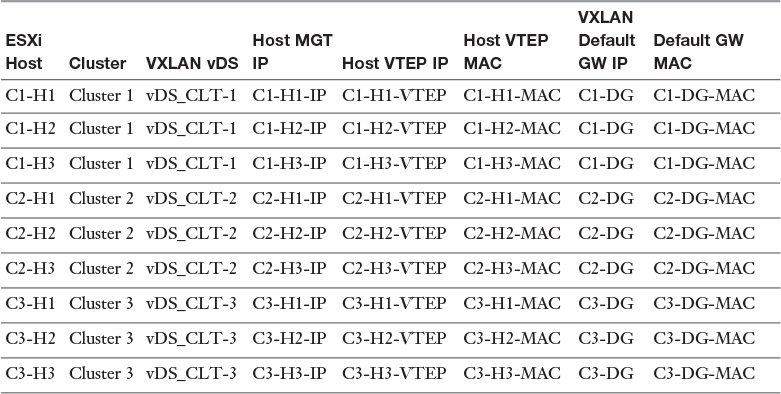
Table 6-2 shows where each VM is running, its IP address, and its MAC address. The naming convention used is Cluster#-Machine# and Cluster#-Host#.
Table 6-3 shows each ESXi host’s management IP address, VTEP IP address, and VTEP MAC address.
In this packet walk, Virtual Machine C1-M1 sends a frame to Virtual Machine C1-M2. Assume the following to be true:
All VMs have been powered on for some time.
C1-M1 and C1-M2 are connected to Universal Logical Switch 7321.
C1-M1 and C1-M2 are using the MAC addresses in their vmx files.
Logical Switch 7321 is configured with MAC learning.
NSX Universal Controller NC-2 is responsible for VNI 7321.
C1-M1 knows the MAC address of C1-M2.
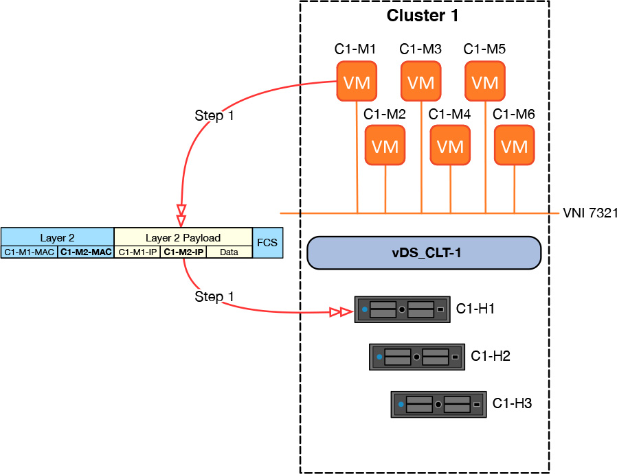
Step 1. C1-M1 sends a frame with the source IP C1-M1-IP, destination IP of C1-M2-IP, Source MAC of C1-M1-MAC, and destination MAC of C1-M2-MAC, as shown in Figure 6-3.
Step 2. Logical Switch 7321 in ESXi host C1-H1 receives the frame from C1-M1 and reads the source MAC address, C1-M1-MAC.
Step 3. Because the source MAC address C1-M1-MAC is the same MAC address in the vmx file of C1-M1, it is already in the MAC table of logical switch 7321 in C1-H1 (courtesy of the vDS being used for VXLAN). The logical switch moves on to read the destination MAC address of the frame.
Step 4. Because the destination MAC address C1-M2-MAC is the same MAC address that is in the vmx file of Virtual Machine C1-M2, then the MAC address is already in logical switch 7321 MAC table in C1-H1 (again, courtesy of the vDS...thank you vDS).
Step 5. Logical switch 7321 in C1-H1 delivers the frame to C1-M2.
Now that was easy. This packet walk had an identical behavior to that of the vDS with a VLAN dvPortgroup, except for the MAC learning part. If MAC learning was not configured in the logical switch, the behavior would be identical to the vDS with a VLAN dvPortgroup where the source MAC address of the virtual machine’s frame is not read. Let’s raise the temperature a notch by doing a slightly different packet walk.
In this packet walk, Virtual Machine C1-M1 sends a frame to Virtual Machine C1-M2. Assume the following to be true:
C1-M1 and C1-M2 are connected to Universal Logical Switch 7321.
C1-M1 and C1-M2 are using MAC addresses not in their vmx file.
Logical Switch 7321 is configured with MAC learning.
NSX Universal Controller NC-2 is responsible for VNI 7321.
C1-M1 knows the MAC address of C1-M2.
Step 1. C1-M1 sends a frame with the source IP of C1-M1-IP, destination IP of C1-M2-IP, Source MAC of C1-M1-MAC, and destination MAC of C1-M2-MAC.
Step 2. Logical Switch 7321 in ESXi host C1-H1 receives the frame from C1-M1 and reads the source MAC address, C1-M1-MAC.
a. If the MAC address is not in its MAC table, logical switch 7321 in C1-H1 will add it to its MAC table and tell the NSX Controller NC-2 if the Replication Mode for the logical switch is Unicast or Hybrid.
b. If the MAC address is in the MAC table of logical switch 7321 in C1-H1 but it shows as belonging to a different virtual machine in C1-H1, it will update its MAC table and not tell NC-2.
c. If the MAC address is in the MAC table of logical switch 7321 in C1-H1 but it shows as belonging to a different virtual machine in a VTEP different from C1-H1, it will update its MAC table and tell NC-2 if the Replication Mode for the logical switch is Unicast or Hybrid.
In each case a copy of the MAC address will also be given to the Switch Security module. If C1-M1 used an 802.1Q tab, the VLAN number will also be given to the Switch Security module; otherwise, the VLAN number given to the Switch Security module is 0.
Step 3. Logical switch 7321 in C1-H1 reads the destination MAC address C1-M2-MAC.
If the destination MAC address is not in the MAC table of logical switch 7321 in C1-H1, the logical switch will query NC-2 for the MAC address if the Replication Mode for the logical switch is Unicast or Hybrid. If C1-H1 does not receive a response from NC-2, NC-2 is down, or if the Replication Mode is Multicast, the logical switch will replicate the frame.
In this case, since the MAC C1-M2-MAC is local to C1-M2, it is expected that NC-2 will not have an entry for it.
Logical Switch Packet Walk Example 4 reviews Replication Modes in more detail.
Step 4. Following step 3, logical switch 7321 in C1-H1 forwards the frame to C1-M2.
Once C1-M2 replies back to C1-M1 using source MAC address C1-M2-MAC, logical switch 7321 in C1-H1 will learn it, as explained in step 2a.
How are you feeling? Or better yet, are you FEELING it? The temperature is rising with these packet walks. Next let’s bring the heat up until it gets to Florida hot. The next packet walk follows a frame between virtual machines in different ESXi hosts.
In this packet walk, Virtual Machine C1-M3 sends a frame to Virtual Machine C2-M4. Assume the following to be true:
C1-M3 and C2-M4 are connected to Universal Logical Switch 7321.
C1-M3 and C2-M4 are using the MAC addresses in their vmx files.
Logical switch 7321 is configured with MAC learning.
NSX Universal Controller NC-2 is responsible for VNI 7321.
C1-M3 knows the MAC address of C2-M4.
C1-M3 and C2-M4 have communicated with each other recently (around 200 seconds).
Step 1. C1-M3 sends a frame with the source IP C1-M3-IP, destination IP of C2-M4-IP, Source MAC of C1-M3-MAC, and destination MAC of C2-M4-MAC.
Step 2. Logical switch 7321 in ESXi host C1-H2 receives the frame from C1-M3 and reads the source MAC address, C1-M3-MAC.
The source MAC address C1-M3-MAC is the same MAC address in the vmx file of C1-M3; it is already known by logical switch 7321 in C1-H2.
Step 3. Logical switch 7321 in C1-H2 reads the destination MAC address. The destination MAC address C2-M4-MAC is in the MAC table because it has recently seen traffic coming from C2-M4.
The MAC table of logical switch 7321 in C1-H2 has the following entries, as shown in Table 6-4.
Step 4. Logical switch 7321 passes the frame from C1-M3 to the VXLAN module to create a VXLAN encapsulation.
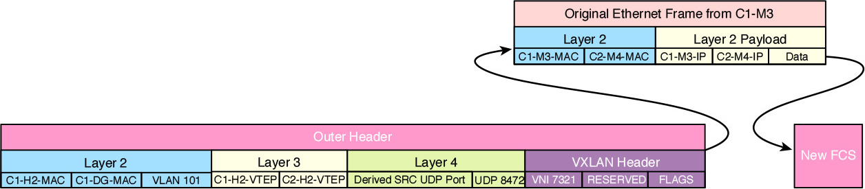
Step 5. The VTEP in C1-H2 encapsulates the frame using the following information, as shown in Figure 6-4. Note that a new Frame Check Sum (FCS) replaces the FCS from C1-M3.
VNI: 7321
Source UDP Port: Derived from the frame sent by C1-M3
Destination UDP Port: 8472 (the default port, this can be changed with an NSX API call)
Source IP: C1-H2-VTEP
If C1-H2 had multiple VTEPs, the VXLAN module would have used the IP of the VXLAN VMkernel port (VTEP) to which C1-M3 was pinned.
Destination IP: C2-H2-VTEP
Source MAC: C1-H2-MAC
If C1-H2 had multiple VTEPs, the VXLAN module would have used the MAC of the VXLAN VMkernel port (VTEP) to which C1-M3 was pinned.
Destination MAC: C1-DG-MAC
Remember from Chapter 5 that an Outer MAC of all Fs (refer to Table 6-4) means the destination MAC will be the MAC of the default gateway in the VXLAN TCP/IP Stack.
802.1Q VLAN: 101
Not shown in the diagram are these two fields:
DSCP value: Copied from frame sent by C1-M3, if honored or not overwritten by vDS
802.1Q CoS: Copied from frame sent by C1-M3, if honored or not overwritten by vDS
Step 6. The underlay switch C1-SW receives the VXLAN frame, examines the VXLAN Layer 2 header, and forwards it to the default router over interface C1-DG.
C1-SW conducts regular Ethernet switch processing, such as MAC learning and CoS enforcement, on the VXLAN Layer 2 header.
Important: The interface from C1-H2 connecting to C1-SW is configured as a Trunk allowing VLAN 101.
Important: If the default gateway interfaces are not configured as Trunk, thus their switch ports are set up as access ports. Switch C1-SW removes the VLAN tag from the VXLAN frame before sending it to the default gateway.
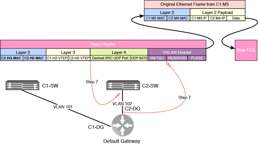
Step 7. The default gateway receives the frame over interface C1-DG, processes the VXLAN Layer 3 header, does CoS enforcement, and routes the packet over interface C2-DG.
If the default gateway is executing a firewall function, it may also inspect the VXLAN Layer 4 header.
The VXLAN Layer 2 header is changed by the default gateway to include these new values, as shown in Figure 6-5.
Source MAC: C2-DG-MAC
Destination MAC: C2-H2-MAC
Note
Every time a frame crosses Layer 2 boundaries (goes through a router), the FCS is dropped and a new one is created.
Note
The default gateway does not add a VLAN tag of 102 to the VXLAN frame since it is not a Trunk port. The switch C2-SW does that when it forwards the frame to C2-H2 via the Trunk port.
Step 8. The overlay switch C2-SW receives the VXLAN frame from the default gateway, examines the VXLAN Layer 2 header, and forwards it to C2-H2.
Important: C2-DG is connected to an access port in switch C2-SW in VLAN 102. All frames that arrive from interface C2-DG are placed in VLAN 102.
Important: The interface C2-H2 connecting to C2-SW is configured as a Trunk allowing VLAN 102.
Step 9. C2-H2 receives the frame over VXLAN VMkernel port MAC address, C2-H2-MAC.
The VXLAN module in C2-H2 reads the VNI, 7321, in the VXLAN frame, decapsulates the VXLAN frame, and passes the frame from C1-M3 to logical switch 7321 in C2-H2 for processing.
Step 10. Logical switch 7321 in C2-H2 reads the source MAC address, C1-M3-MAC.
Logical switch 7321 in C2-H2 already has MAC address C1-M3-MAC in its MAC table because it has recently seen traffic coming from C1-M3.
Step 11. Logical switch 7321 in C2-H2 then reads the destination MAC address, C2-M4-MAC, sees that it knows which virtual machine owns it, and passes the frame to Virtual Machine C2-M4.
Logical switch 7321 in C2-H2 knows MAC address C2-M4-MAC because C2-M4-MAC is in the vmx file of C2-M4.
Well, if you can’t take the heat, stay in the Northeast (or is it don’t go in the kitchen?). And since you are reading this book, you must want to be a chef—an “NSX chef.”
This packet walk demonstrates some of the advantages of logical switches (global logical switches and universal logical switches). First, it shows how the Ethernet broadcast domain to which the VMs are connected can be extended across an IP network. For all we know, Cluster-1 could be located in one end of Data Center A in Santo Domingo, Dominican Republic; Cluster-2 could be located at the other end of Data Center A; and Cluster-3 could be located in Data Center B in Tampa, Florida.
Second, there is no Spanning Tree, TRILL, or any other Layer 2 loop-avoiding technology in place. All traffic outside the clusters’ local VTEP subnet goes over Layer 3, IP, which has built-in loop avoidance mechanisms. Yes, you could deploy all VTEPs to be in the same VTEP subnet, necessitating the VTEP VLAN to be extended among all the clusters; however, unless you already have an underlay that has Layer 2 loop-avoiding technology, you don’t have to—nor should you, to be honest.

Third, and an important feature to be aware of as we decide which Top of Rack (ToR) switches to deploy: The underlay never learns the MAC addresses of any VMs. Neither C1-SW or C2-SW read the MAC addresses of C1-M3 or C1-M4. The same was true for the default gateway. The underlay only needs to learn the MAC addresses of the VMkernel ports (the VTEPs), in addition to the MAC address of the default gateway, as they are the source/destination of the VXLAN frame in this example. The number of MAC addresses the ToR or End of Row (EoR) needs to have in its MAC table dramatically decreases when using VXLAN.
Let’s take this thing to the top by raising the heat once more. In the next packet walk we follow a BUM in the form of an ARP request from a VM connected to our Universal Logical Switch 7321.
If you’ve been reading over these packet walks in one sitting, perhaps you should take a rest after this next packet walk to digest what we have discussed. Sip on a Piña Colada and come back to it later.
This packet walk explores what happens when an ARP request is sent. We take this packet walk all the way home, including the replication required for its delivery.
Virtual Machine C2-M5 wants to communicate with Virtual Machine C3-M3. Assume the following to be true:
C2-M5 and C3-M3 are connected to Universal Logical Switch 7321.
C2-M5 and C3-M3 are using the MAC addresses in their vmx files.
Logical Switch 7321 is configured with MAC learning.
NSX Universal Controller NC-2 is responsible for VNI 7321.
C2-M5 knows the IP address of C3-M3 but not the MAC address.
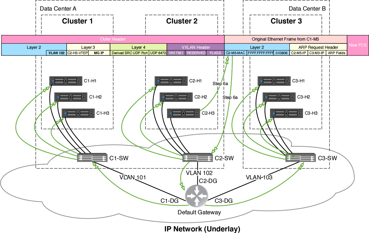
Step 1. Virtual Machine C2-M5 sends an ARP request with the sender IP C2-M5-IP, target IP of C3-M3-IP, Source MAC of C2-M5-MAC, destination MAC of all Fs, Ethernet broadcast, and an Ethertype of 0X0806 (ARP Request), as shown in Figure 6-6.
Step 2. The Switch Security module in ESXi host C2-H3 inspects the frame after realizing it is an ARP request and checks its ARP table for VNI 7321.
If the Switch Security module in C2-H3 has an entry for the ARP request in its ARP table, it will directly respond to C2-M5 and that would be the end of this packet walk. Instead, let’s assume the Switch Security module does not have an entry in its ARP table for the ARP request.
Step 3. The Switch Security module C2-H3 sends a request to NSX Controller NC-2 for the ARP entry in the ARP table.
If NC-2 has an entry, it will reply back to the Switch Security module in C2-H3 with the entry. The Switch Security module in C2-H3 will add the entry to its ARP table, and directly respond to C2-M5. Again this would be the end of our packet walk. Instead, let’s assume that either:
NC-2 does not have an ARP entry for our ARP request and responds back to C2-H3 with FFFF.FFFF.FFFF, which translates in English to “I don’t have an entry for IP C3-M3-IP.”
NC-2 is down or unresponsive.
Replication Mode is set to Multicast.
Step 4. The Switch Security module ESXi host C2-H3 hands the frame to the logical switch 7321.
Step 5. Logical switch 7321 in ESXi host C2-H3 forwards a copy of the ARP request to all local virtual machines, except C2-M5.
Step 6. Logical switch 7321 in C2-H3 hands the frame to the VXLAN module to replicate the ARP request.
Important: If not using Multicast Replication Mode, the VTEP consults its copy of the VTEP table to determine where to send the replicated frames. In our case, where all VMs are powered on, all ESXi hosts are in the VTEP table.
Note
We are skipping the underlay steps. They are almost identical to the steps in “Logical Switch Packet Walk Sample 3.”
a. If using Multicast Replication Mode, a single VXLAN frame is sent out by C2-H3 with a destination IP of the multicast group assigned to VNI 7321, as shown in Figure 6-7. In this example, all ESXi hosts will have joined the multicast group and thus receive the multicast frame.
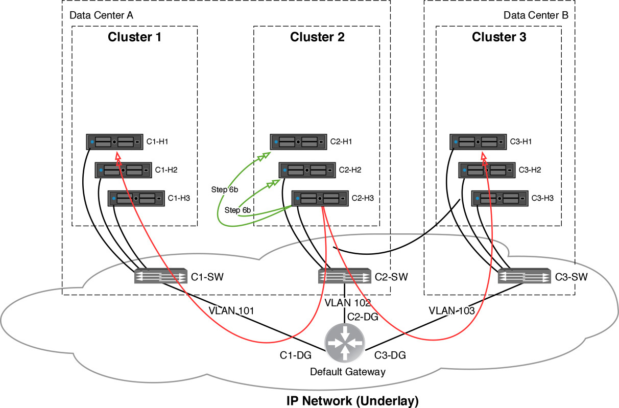
b. If using Unicast Replication Mode, ESXi host C2-H3 sends out unicast VXLAN frames, one each to C2-H1 and C2-H2 in the local VXLAN subnet, and one each to the proxy VTEPs C1-H1 and C3-H1, as shown in Figure 6-8. The proxy VTEPs are locally chosen by C2-H3 per remote VTEP subnet. We are going to assume that C2-H3 chose as proxy VTEPs C1-H1 and C3-H1.
The unicast to the proxy VTEPs will have its Replication bit set to 1. Figure 6-9 shows the VXLAN frames that are sent by C2-H3.
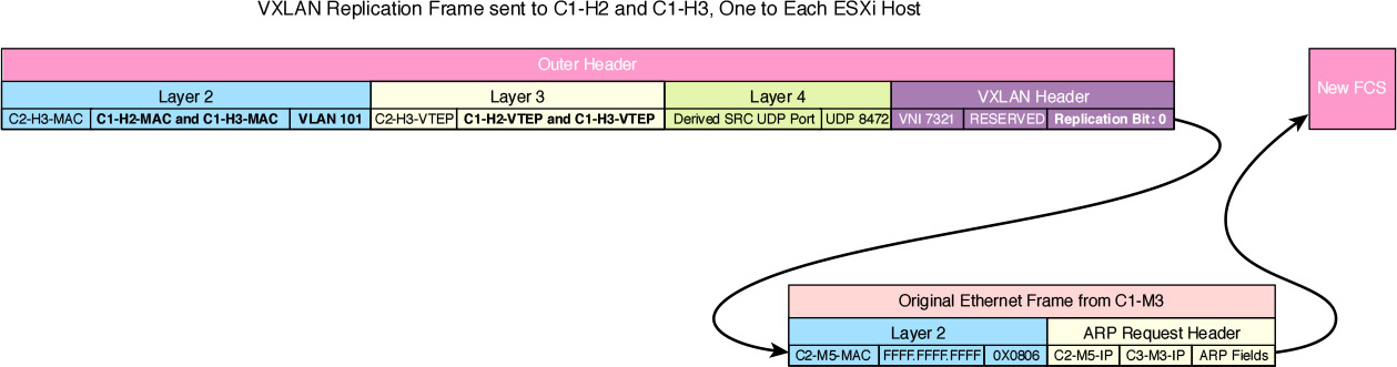
Because C1-H1 and C3-H1 are UTEPs, each one in turn sends unicast VXLAN frames to their local VTEPs, with the Replication bit set to 0.
C1-H1 sends the unicast VXLAN frame to C1-H2 and C1-H3. Figure 6-10 shows the two VXLAN frames that are sent by C1-H1.
C3-H1 sends the unicast VXLAN frame to C3-H2 and C3-H3. Figure 6-11 shows the two VXLAN frames that are sent by C1-H1.
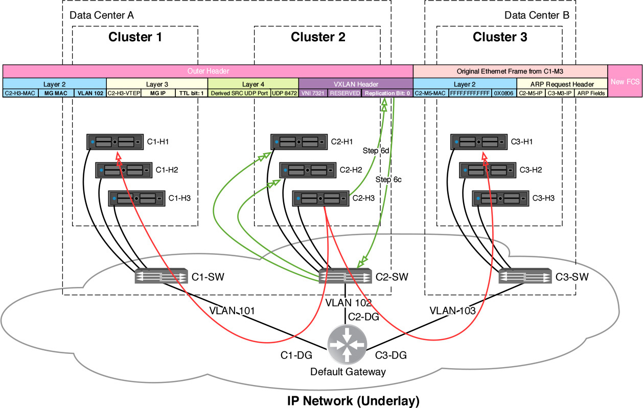
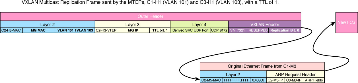
c. If using Hybrid Replication Mode, a single multicast VXLAN frame is sent out by C2-H3 with a destination IP of the multicast group assigned to VNI 7321 and the TTL set to 1, and two unicast VXLAN frames are sent out by C2-H3, one to each proxy VTEP C1-H1 and C3-H1, as shown in Figure 6-12.
The unicast to the proxy VTEPs has its Replication bit set to 1, just like in Figure 6-10.
Because C1-H1 and C3-H1 are MTEPs, each one in turn sends a single multicast VXLAN frame with a destination IP of the multicast group assigned to VNI 7321, the TTL set to 1, and the Replication bit set to 0. Figure 6-13 shows the VXLAN replication frame sent by the MTEPs.
Step 7. All VTEPs that receive the replicated VXLAN frame have to process it, read the VNI, 7321, in the VXLAN frame, decapsulate the frame, and broadcast the ARP request to all running VMs in logical switch 7321.
In the process of doing this, all logical switches with a VNI of 7321 in every ESXi host learn that MAC address C2-M5-MAC is on C1-H3-VTEP and add it to their MAC tables, and set the dead timer to about 200 seconds.
Step 8. C3-M3 receives the ARP request and responds with an ARP reply.
The ARP reply has a destination MAC address of C2-M5-MAC.
Step 9. The Switch Security module in C3-H2 inspects the frame from C3-M3, realizes it is an ARP reply, and adds the entry to its ARP table.
Step 10. Because C3-M3 is running in C3-H2, the Switch Security module in 7321 in C3-H2 sends an IP report to NC-2 with the new ARP entry so it can also add it to its ARP table.
Step 11. The Switch Security module passes on the ARP reply to logical switch 7321 in C3-H2.
I’m skipping the part where logical switch 7321 in C3-H2 does MAC learning by reading the source MAC address. You should have that part locked down by now.
Step 12. Logical switch 7321 in C3-H2 reads the destination MAC address of the ARP reply, C2-M5-MAC, looks in its MAC table, and finds an entry for it pointing to C2-H3-VTEP.
Reread step 7 above if you don’t quite see why the entry is in the MAC table.
Step 13. Logical switch 7321 in C3-H2 passes the frame to the VXLAN module for VXLAN frame creation.
This would be a unicast VXLAN frame with a destination IP of C2-H3-VTEP and destination MAC of C3-DG-MAC.
Step 14. C2-H3 receives the VXLAN frame, processes the frame by reading the VNI number, 7321, and decapsulates it.
Step 15. Logical switch 7321 reads the source MAC address of the ARP reply and adds it to its MAC table pointing towards C3-H2-VTEP, with a dead timer of about 200 seconds.
Step 16. Logical switch 7321 then reads the destination MAC address of the ARP reply, C2-M5-MAC, looks it up in the ARP table, and forwards the frame to C2-M5.
Step 17. The Switch Security module in C2-H3 intercepts the frame before it reaches in C2-M5, notices it is an ARP reply, and adds the entry to its ARP table. Then the frame is forwarded to C2-M5.
The Switch Security module in C2-H3 will not tell NC-2 about it because the ARP reply did not come from a virtual machine running in C2-H3.
I briefly mentioned in Chapter 4, “VXLAN, NSX Controllers, and NSX Preparation,” that the Switch Security module helps with Layer 2 broadcast suppression. The Switch Security module (VMware likes to shorten it to SwSec dvFilter) sits between the VM’s vNIC and the logical switch. The Switch Security module occupies a slot in the ESXi host’s IOChain. The Switch Security module occupies Slot 1 of the IOChain. All traffic leaving (egress) the virtual machine is inspected by the Switch Security module before reaching the logical switch. The Switch Security module only inspects, or snoops, interesting frames if they are an ARP request, ARP reply, or DHCP offer. All interesting traffic coming to (ingress) the VM also is snooped, after leaving the logical switch and before reaching the VM, by the Switch Security module.
This is what I call Caribbean hot. Let me take a minute to give my fingers a rest, have that Piña Colada, and take a dive in the pool.
This last packet walk was action packed (pun kind of intended). We reviewed the different modes of replication as well as all the different options that could be taken when an ARP request is sent by a VM. In all instances, the originator of the +ARP request gets a response if the owner of the IP is reachable. In the case where replication is invoked, there was the added bonus that the MAC tables of the logical switches (of the ESXi hosts in the VNI’s VTEP table) were updated.
I’m feeling the juices flowing again now that my fingers are no longer sore. Let’s do one more packet walk, this time having a virtual machine vMotion.
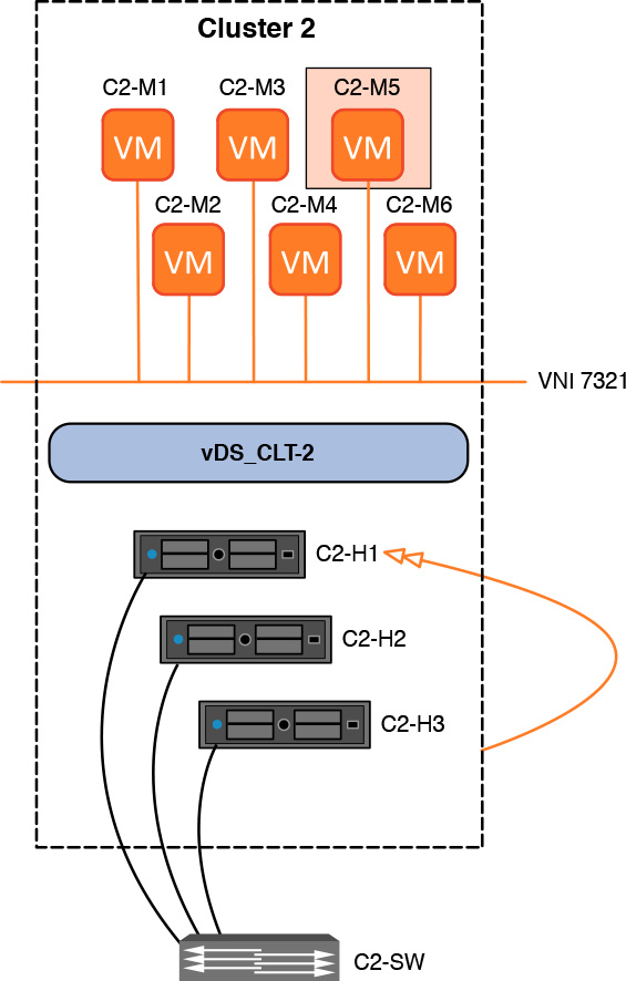
In the next and last packet walk, C2-M5 will vMotion to ESXi host C2-H1, as shown in Figure 6-14. I’ve removed all other VMs to clean up the diagram a bit. Before reading on, take a few moments to review the roles of the VTEP table, MAC table, and ARP table. We touch on each of those as we do the next packet walk.
Step 1. The vSphere administrator, or DRS, initiates a vMotion for Virtual Machine C2-M5.
Important: This is where the Switch Security module plays a role of informing the vMotion destination host, C2-H1, about the MAC addresses that C2-M5 has.
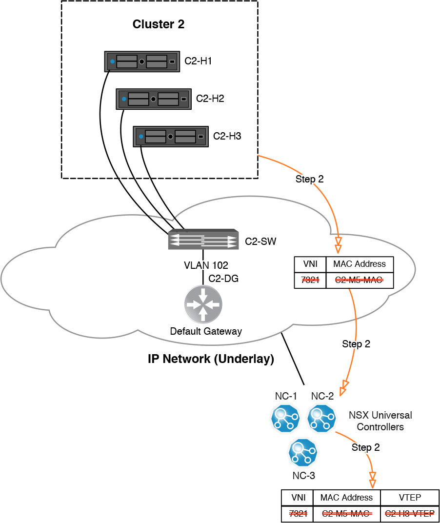
Step 2. When vMotion is completed, ESXi host C2-H3 updates the NSX Controller that it no longer has the MAC address of C2-M5-MAC, as shown in Figure 6-15.
If C2-M5 was the last powered on VM in logical switch 7321 in host C2-H3, C2-H3 will also send the NSX Controller a request to remove its VTEP, C2-H3-VTEP, from the 7321’s VTEP table. At this point, the NSX Controller would update the VTEP table, removing C2-H3-VTEP, and send a copy of the updated VTEP table to all other hosts that have a VTEP in the VTEP table.
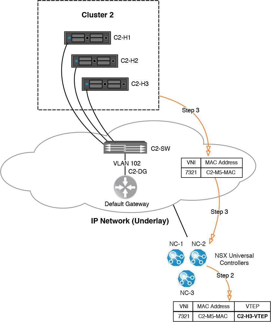
Step 3. ESXi host C2-H1 updates the NSX Controller that it has the MAC address C2-M5-MAC, as shown in Figure 6-16, as well as all other MAC addresses associated with C2-M5 (which the Switch Security module in C2-H3 told C2-H1 about).
Figure 6-16 The NSX Controller adds in the MAC table the MAC entry for C2-M5-MAC pointing to C2-H1 VTEP.
Step 4. Host C2-H1 sends a RARP on behalf of C2-M5, for all MAC addresses associated with C2-M5.
The RARP is used to update the MAC table of switches. It has as a source the MAC to be updated in the MAC table and a destination MAC of all Fs.
Step 5. Following the Replication Mode configured in the logical switch, the RARP is replicated to all ESXi hosts in the VTEP table or belonging to the multicast group for VNI 7321.
Review step 6 in the Logical Switch Packet Walk Example 4.
Step 6. All ESXi hosts receiving the RARP add an entry in their local MAC table for VNI 7321 for MAC C2-M5-MAC, including the local MAC table on host C2-H3, the vMotion source host.
The MAC entry is added in VNI 7321’s MAC tables of each logical switch in the ESXi host, with a dead timer of five minutes.
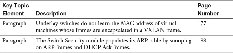
Review the most important topics from inside the chapter, noted with the Key Topic icon in the outer margin of the page. Table 6-5 lists these key topics and the page numbers where each is found.
Define the following key terms from this chapter, and check your answers in the Glossary: