Objective 5.1—Create and Administer Logical Switches
This chapter covers all or part of the following VCP6-NV exam blueprint topics:
Objective 5.1—Create and Administer Logical Switches
Objective 5.2—Configure VXLAN
Objective 8.1—Differentiate Single and Cross-vCenter NSX Deployments
Objective 8.2—Determine Cross-vCenter Requirements and Configurations
Your team is in charge of the vSphere environment at your company. Your company has experienced substantial growth over the last two quarters, and forecasts show the growth will continue at the same rate over the next four quarters. You have been tasked to prepare the IT infrastructure to allow for the quick expansion of existing Ethernet broadcast domains to support the virtual machines (VMs) that will be deployed in support of your company’s phenomenal growth. Making frequent changes to the physical networks is not a viable alternative. So what options do you have? NSX switches.
NSX switches allow for the extension of Ethernet broadcast domains over any IP network without requiring any configuration changes to that network (beyond those discussed in Chapter 2, “Network and VMware vSphere Requirements for NSX,” and Chapter 4, “VXLAN, NSX Controllers, and NSX Preparation”). This chapter goes deeper into the two types of NSX switches, the logical switch and the universal logical switch, and what all the fuss about them is. Hint: The fuss is warranted.
The “Do I Know This Already?” quiz allows you to assess whether you should read this entire chapter or simply jump to the “Exam Preparation Tasks” section for review. If you are in doubt, read the entire chapter. Table 5-1 outlines the major headings in this chapter and the corresponding “Do I Know This Already?” quiz questions. You can find the answers in Appendix A, “Answers to the ‘Do I Know This Already?’ Quizzes.”
1. Which statement is true regarding logical switches?
a. A global logical switch supports a single VXLAN network ID.
b. A universal logical switch supports all the broadcast domains in a cross vCenter NSX domain.
c. A universal logical switch supports up to 64 ESXi hosts.
d. Global logical switches have their own VXLAN table.
2. How many logical switches may be deployed in an NSX domain?
a. 1
b. 4095
c. 10,000
d. 16,777,216
3. Which two entries are not present in the VTEP table? (Choose two.)
a. The VTEP IP
b. The VTEP subnet mask
c. The VTEP MAC address
d. The ESXi host management IP
4. How does a universal logical switch learn the MAC address assigned by the ESXi host to a connected vNIC of a virtual machine?
a. Via MAC learning. The logical switch reads the source MAC address of frames sent by the virtual machine.
b. From the NSX universal controller. The NSX Controller updates the logical switch with the MAC address of the virtual machine.
c. From the vmx file. The logical switch reads the MAC address of the virtual machine by looking in the virtual machine’s vmx file.
d. From the Primary NSX Manager. NSX Manager obtains virtual machine MAC addresses from vCenter and then updates the logical switch.
5. Which entity populates the ARP table?
a. The distributed firewall.
b. The NSX Controller.
c. The universal logical switch.
d. The Security module.
6. What action does a logical switch take if it receives a non-ARP broadcast when configured with Hybrid Replication Mode?
a. The logical switch sends a multicast to all ESXi hosts in the NSX domain.
b. The logical switch sends a multicast to all ESXi hosts in the global transport zone.
c. The logical switch sends a broadcast to all ESXi hosts in the same VTEP subnet.
d. The logical switch sends a unicast to all proxy VTEPs.
7. What two actions does a universal logical switch take if it receives an unknown unicast when configured with Unicast Replication Mode? (Choose two.)
a. The universal logical switch sends a multicast to all ESXi hosts in the NSX domain.
b. The universal logical switch sends a MAC table query to the NSX universal controller responsible for the universal logical switch where the frame was received.
c. The universal logical switch sends a multicast to all ESXi hosts in the universal transport zone.
d. The universal logical switch sends a unicast to all ESXi hosts in the same VTEP subnet.
8. In what two locations is the Replication Mode configured for a logical switch? (Choose two.)
a. In NSX Manager
b. In the NSX Controller
c. In the global transport zone
d. In the logical switch
9. What is an advantage of Multicast Replication Mode?
a. Each VTEP has a list of all VTEPs with powered on virtual machines.
b. The underlay does not have to be configured with multicast.
c. The source VTEP only sends one replication VXLAN frame.
d. The NSX Controller communicates with ESXi hosts in the VTEP table via multicast.
10. What is a disadvantage of Unicast Replication Mode?
a. If the MAC table is large, the source VTEP will drop the BUM.
b. If the VTEP table is large, the source VTEP will have to send many replication VXLAN frames.
c. If the VTEP table is large, the source VTEP will drop the BUM.
d. If the MAC table is large, the source VTEP will only send the replication VXLAN frame if the underlay is configured for multicast.
Simply stated, a global logical switch and a universal logical switch are virtual switches that are distributed and use VXLAN Network Identifiers (VNIs) instead of VLAN numbers to label Ethernet broadcast domains. The ESXi host running a virtual machine connected to a global logical switch or a universal logical switch has the source VXLAN Tunnel End Point (VTEP) for any Layer 2 traffic from the virtual machine with a destination MAC address residing in a different VTEP. Both the global logical switch and the universal logical switch support a single Ethernet broadcast domain, which means they both support only a single VNI. Because of the one-to-one relation between the logical switch and the assigned VNI, the names logical switch and VNI are often used interchangeably.
You might have noticed from this first paragraph that the global logical switch and the universal logical switch seem to have the same feature. That is because they are almost identical with respect to what they are and what they support. The only difference between a global logical switch and the universal logical switch is the transport zone. Global logical switches are the NSX switches belonging to a global transport zone. Universal logical switches are the NSX switches belonging to the universal transport zone. For the rest of this chapter, I simply refer to both of them as logical switches except where I need to make a point or clarify a feature.
Because the logical switch is distributed in nature, NSX Manager owns the management plane of the logical switch (and the Primary NSX Manager for the universal logical switch), while each ESXi host owns its own data plane for the logical switch. The NSX Controllers, or NSX universal controllers, handle most of the control plane for the logical switches. The ESXi hosts with VMs connected to a logical switch handle the control plane for those VMs.

The ESXi host’s local copies of the MAC tables contain the MAC addresses of all locally running VMs, per logical switch. The MAC tables also have any remote MAC addresses from any active flows in the logical switch where one of its VMs is the destination. If the logical switch does not see activity from the remote MAC address for more than five minutes, the logical switch in the ESXi host flushes the MAC entry from the MAC table. In other words: The logical switch in the ESXi host does MAC learning for external sources.
So what is MAC learning? It is what physical switches have been doing for the last 30 years or so. For every ingress Ethernet frame from the overlay that is processed by the logical switch in an ESXi host, the logical switch reads the source MAC address. If the source MAC address is not in the logical switch’s MAC table, the logical switch adds it to its MAC table. If the source MAC address is in the logical switch’s MAC table but it arrived at the logical switch via a path different from what is in the MAC table, the logical switch updates the path in the MAC table. Table 5-2 shows the MAC table of ESXi host C4-H4 with a logical switch with VNI 7321.
The output of Table 5-2 was obtained from the NSX Manager privilege CLI command show logical-switch host [host-id] vni 7321 mac. The same output may be obtained directly from the ESXi host by using the command esxcli network vswitch dvs vmware vxlan network mac list --vds-name=[vDS used by VXLAN] --vxlan-id=7321. I reformatted the output into a table and added the VNI column (it is not part of the actual output) to make it easier to read. The Inner MAC column is the MAC address of the remote entity (the learned MAC address). The Outer MAC column is the MAC address of the destination MAC of the VXLAN frame created to forward traffic to the Inner MAC. The Outer IP is the destination IP of the VXLAN frame (the destination VTEP). If the Outer IP is in a different subnet from the source Outer IP (source VTEP), then the Inner MAC address is listed as all Fs. All Fs tells the source VTEP to use its VXLAN TCP/IP stack default gateway to reach the Outer IP.
The logical switch does not, by default, do MAC learning for traffic sourced directly from connected VMs. Instead, the logical switch learns the VM’s MAC address from the vmx file of the VM. This default behavior can be changed in the logical switch.
Logical switches are created via the NSX Manager that owns the transport zone where the logical switch will be added. Logical switches may be created via the vSphere Web Client or by using the NSX APIs. Either way, you must be an NSX enterprise or NSX administrator to create a logical switch.
Global logical switches must be assigned to a global transport zone at the time of creation. Universal logical switches must be assigned to the universal transport zone at the time of creation. A few paragraphs ago I stated that logical switches are a type of distributed switch. In reality, logical switches are represented, or backed, at the ESXi host by a dvPortgroup in the vDS assigned to each NSX cluster during logical network preparation, covered in Chapter 4.
Being backed by a dvPortgroup has implications for the number of logical switches that can be deployed in the NSX domain and how big a Segment ID pool can be. Each vCenter can support a maximum of 10,000 dvPortgroups; therefore, the maximum number of logical switches that can be deployed in an NSX domain (global logical switches and universal logical switches combined) is also 10,000. It should be stressed that if vCenter was able to support 16,777,216 dvPortgroups, that’s how many logical switches would be supported in the NSX domain or Cross vCenter NSX domain.
The steps to create a logical switch via the vSphere Web Client are as follows:
Step 1. From the Networking and Security page, select Logical Switches.
Step 2. Select the NSX Manager where you are creating the logical switch.
If creating a universal logical switch, select the Primary NSX Manager.
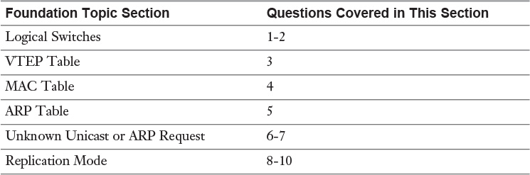
Step 3. Click the green + icon and wait for the Logical Switch Wizard to open, as shown in Figure 5-1.
Step 4. Assign a name to the logical switch. Two logical switches can’t have the same name.
Step 5. Select the Transport Zone for the logical switch.
Select the Global Transport Zone to make this a global logical switch.
Select the Universal Transport Zone for cross vCenter NSX to make this a universal logical switch.
Multiple global logical switches can be in the same global transport zone.
Multiple universal logical switches can be in the same universal transport zone.
Step 6. Optionally, choose a Replication Mode if you want it to be different from the one configured in the transport zone. We talk more about Replication Mode later in this chapter.
Step 7. Optionally, check the Enable MAC Learning box. This enables MAC learning for traffic coming from virtual machines.
You should only enable this feature if you will have VMs sourcing traffic using a MAC different from the one in the vmx file, such as Security Appliances (IPS/IDS), Guess OS MAC Cloning, and so on.
Step 8. Click OK.
If you create the global logical switch via the vSphere Web Client, the vSphere Web Client passes along the request to vCenter, which forwards it to the corresponding NSX Manager. If you create the global logical switch via the NSX APIs, then NSX Manager gets the request directly. If creating a universal logical switch via the vSphere Web Client, the vSphere Web Client passes the request to the vCenter of the Primary NSX Manager, which then passes it along to the Primary NSX Manager.
Regardless of how NSX Manager gets the request, the following workflow takes place:
Step 1. If creating a global logical switch, NSX Manager selects a VNI from the Segment ID pool created during Segment ID preparation, reviewed in Chapter 4.
If needed, NSX Manager selects a multicast group from the Multicast pool created during Segment ID preparation.
If this is a universal logical switch, the Primary NSX Manager selects a VNI from the Universal Segment ID pool and a multicast group from the Universal Multicast pool. These would be shared via NSX universal synchronization with the Secondary NSX Managers.
Step 2. NSX Manager looks up the cluster membership of the transport zone where the logical switch is created to obtain the list of vDSes that will be supporting the logical switch.
These are the same vDSes you configured in the VXLAN transport configuration during logical network preparation in chapter 4.
Step 3. NSX Manager requests its vCenter to create a dvPortgroup for each vDS obtained from the transport zone.
NSX Manager provides the VNI and multicast group (if any) to vCenter as OpaqueNetworks.
OpaqueNetwork is a managed object of the vDS that allows for non-vSphere network features (managed by a non-vSphere entity) to be included in a dvPortgroup.
The dvPortgroup name format for a logical switch is vxw-dvs-[vds MOID]-universalwire-#-sid-[logical switch VNI]-[logical switch name].
For a universal logical switch, this step 3 is done by each NSX Manager in the cross vCenter NSX domain. The Primary NSX Manager only talks to its own vCenter.
Step 4. vCenter creates the dvPortgroup(s) and pushes the new group information to all of its ESXi hosts that belong to the corresponding vDS, including the OpaqueNetwork parameters.
These dvPortgroups have the same VLAN as the VXLAN VLAN and the same VMKnic Teaming Policy configured during host preparation.
When the ESXi hosts receive the OpaqueNetwork VXLAN parameters (VNI, multicast), they automatically start using the VXLAN VIB to process traffic in these dvPortgroups.
Step 5. If the Replication Mode is not multicast, the NSX Manager informs the NSX Controllers about the new logical switch.
This communication takes place with the NSX Controller API provider master, which then passes this information to the NSX Controller L2 master.
In there is a universal logical switch, only the Primary NSX Manager informs the universal NSX Controllers.
Step 6. The NSX Controller L2 master does some slicing and selects one of the NSX Controllers to be responsible for the new logical switch.
This information is replicated among all NSX Controllers (three of them). Any of the NSX Controllers can respond to requests for this information.
Step 7. If the Replication Mode is not multicast, the ESXi hosts in the transport zone send a request to any of the NSX Controllers to find out the NSX Controller responsible for the logical switch.
For universal logical switches, all ESXi hosts in the universal transport zone send the request to the NSX universal controllers. Remember that only the Primary NSX Manager has any NSX Controllers in cross vCenter NSX.
In step 3, notice the name of the dvPortgroup backing the logical switch includes the vDS MOID. The managed object ID (MOID) is a unique identifier used by vCenter to track vSphere objects in its database. vCenter assigns each vDS its own MOID. If multiple vDSes are part of the transport zone, the dvPortgroups backing the logical switch each have a different name. vMotion is a vCenter feature and prior to vSphere 6.0 it required the source and destination dvPortgroups to have the same name. Thus prior to vSphere 6.0 vMotion wouldn’t work for a VM connected to a logical switch if the destination ESXi host had the logical switch backed by a different vDS dvPortgroup. As of vSphere 6.0, vMotion supports migrations to different vdPortgroups names, including those dvPortgroups backing logical switches.
Once the logical switch has been created, you see the new logical switch listed in the Logical Switches view of the Networking and Security page, as shown in Figure 5-2. In this view, you can see the logical switch name, the transport zone to which it belongs, the VNI that has been assigned, and if applicable the multicast group assigned to it. In the Scope column, you can verify whether the logical switch is a global logical switch or a universal logical switch.
You can also verify the dvPortgroups backing the logical switch by going to the vSphere Web Client home page, selecting the Network view and expanding each vDS that belongs in the transport zone. Each vDS has a dvPortgroup with the name format mentioned earlier in this chapter. Selecting any of these dvPortgroups shows them to belong to the same VLAN as the VXLAN VLAN, assigned to the vDS during logical network preparation. Figure 5-3 shows the dvPortgroup backing the universal logical switch with VNI 10000. Notice that the dvPortgroup is assigned to VLAN 12.
Once a logical switch is created, you can migrate VMs to the logical switch. From the Logical Switches view follow these steps:
Step 1. Select the NSX Manager where the VM is located.
Step 2. Select the logical switch where you are connecting the VM.
Step 3. Select the VM icon and wait for the Virtual Machine Migration Wizard to open.
Step 4. From the VM list, find the VM that you want to migrate and check the box next to it.
Step 5. Click Next.
Step 6. For each virtual machine you are migrating, select the vNIC you want to migrate to the logical switch.
Step 7. Click Next.
Step 8. Review your selections and click Finish.
You can validate the VM has been migrated to the logical switch in one of two ways:
From the vSphere Web Client’s Virtual Machine and Templates view, select the VM and confirm it is connected to the dvPortgroup that supports the logical switch.
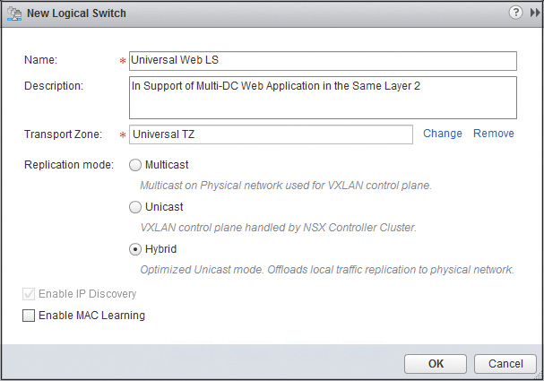
In Logical Switches view, after selecting the NSX Managers where the VM is located, double-click the logical switch to reach the logical switch’s home page and view the list of VMs connected to it, as shown in Figure 5-4.
When a logical switch is created, and before the first VM is migrated to the logical switch, the following is true:
The NSX Controller L2 master has assigned one of the NSX Controllers to be responsible for the logical switch.
All NSX Controllers are informed about which NSX Controller was assigned to the logical switch.
All ESXi hosts in the logical switch’s transport zone have been informed, by the NSX Controllers, which NSX Controller is the one responsible for the logical switch.
The NSX Controllers become aware of the existence of the VNI only if the Replication Mode is not multicast. With Multicast Replication Mode, there is no NSX Controller assigned to the VNI and no communication exchange, about the VNI, between the NSX Controllers and the ESXi hosts in the transport zone.
The question to ask is: What exactly does it mean to be responsible for the logical switch? An NSX Controller being responsible for a VNI means the NSX Controller has the principal copy of these three tables for the logical switch:
The VTEP table
The MAC table
The ARP table
The NSX Controller responsible for the logical switch also keeps a Connection table of every ESXi host that has at least one VM powered on and connected to the logical switch. The Connection table has the Management VMkernel port of the ESXi host, the TCP port of the connection, and a locally significant Connection-ID.
For VMs that are powered on and connected to the logical switch, the VTEP table contains a list of the IP of all the VTEPs that have VMs. The VTEP IP was assigned to the VXLAN VMkernel ports during host configuration. The ESXi hosts in the transport zone update the VTEP table. The ESXi hosts populate the VTEP table for the logical switch when the first VM connects to the logical switch:
1. Powers up in the ESXi.
2. vMotions to the ESXi.
The ESXi host running the VM sends a request to the responsible NSX Controller to have the VTEP added to the VTEP table. Remember that all communication between the ESXi hosts and the NSX Controllers occurs over the Management VMkernel port on the ESXi host using the NETCPA agent over TCP port 1234.
An ESXi host’s VTEPs are removed from the VTEP table upon request by the ESXi host or if the NSX Controller loses communications with the ESXi host. To be removed from the VTEP table, the host sends a request to the NSX Controller when the last VM connects to the logical switch:
1. Powers off.
2. vMotions from the ESXi host.
For its part, the NSX Controller sends a copy of the VTEP table to all ESXi hosts with VTEP entries in the table every time the VTEP table is updated, be it because a VTEP entry is added or a VTEP entry is removed.
The VTEP table has five fields, the first four of which are provided to the NSX Controller by the ESXi hosts:
The VNI
The VTEP IP
The VTEP subnet
The VTEP MAC address
The Connection-ID (matching the Connection ID in the Connection table)
Let’s do a packet walk on how the VTEP table gets populated, and I’m using the term packet walk lightly here since there are no data plane packets flowing around. This packet walk is true if the Replication Mode for the logical switch is configured to Unicast or Hybrid. We discuss this later in the “Replication Mode” section.
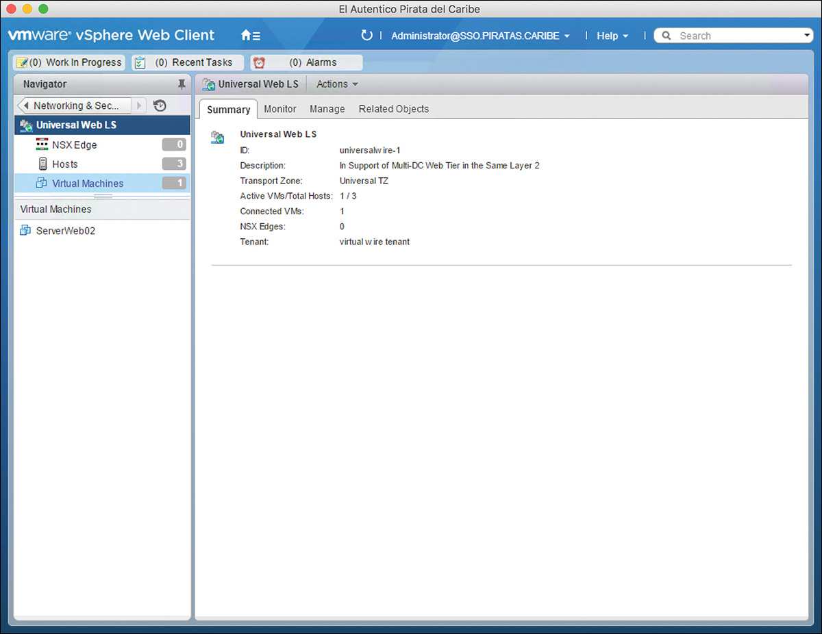
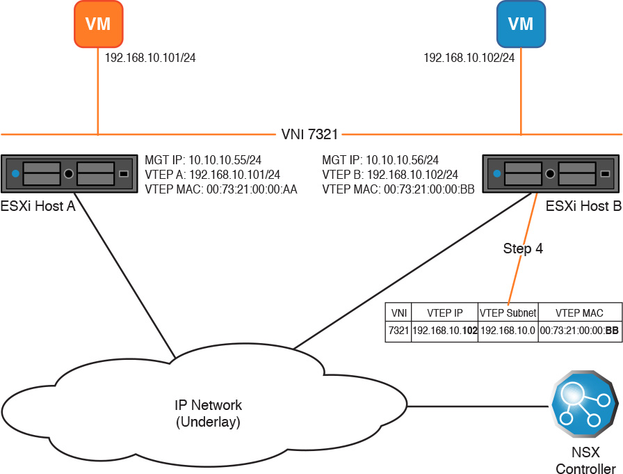
Figure 5-5 shows two ESXi hosts with a logical switch in VNI 7321, each with a VM connected to the logical switch. Each ESXi host has a single VTEP in the same VTEP subnet. Let’s walk through the process of how the VTEP table gets populated.
Step 1. Virtual Machine 1 in ESXi host A powers up.
Step 2. ESXi host A sends a request, from its management VMkernel port over TCP 1234, to the NSX Controller to have its VTEP added to the VTEP table for VNI 7321. The request includes
The VNI
The VTEP IP
The VTEP subnet
The VTEP MAC address
Step 3. The NSX Controller adds the entry to the VTEP table.
Step 4. The NSX Controller sends a copy of the VTEP table to ESXi host A, as shown in Figure 5-6.
Step 5. Virtual Machine 2 in ESXi host B powers up.
Step 6. ESXi host B sends a request to the NSX Controller to have its VTEP added to the VTEP table for VNI 7321. The request includes
The VNI
The VTEP IP
The VTEP subnet
The VTEP MAC address
Step 7. The NSX Controller adds the entry to the VTEP table.
Step 8. The NSX Controller sends a copy of the VTEP table to both ESXi host A and ESXi Host B, as shown in Figure 5-7.
In this second packet walk, let’s see what happens when the last VM in VNI 7321 in an ESXi host is powered down or vMotions. Figure 5-8 shows the state of our environment as we left it in our previous packet walk. In this example, the VM in ESXi host A powers off.
Step 1. The VM in ESXi host A powers off.
Step 2. ESXi host A sends a request to the NSX Controller to be removed from the VTEP table for VNI 7321. At this point ESXi host A flushes its copy of the VTEP table.
Step 3. The NSX Controller receives the request and removes ESXi host A’s VTEP from the VTEP table.
Step 4. The NSX Controller sends a copy of the VTEP table just to ESXi host B, as shown in Figure 5-9.
Earlier we saw a sample MAC table, showing MAC to VTEP mappings, for a logical switch in Table 5-2. Now we discuss how exactly the logical switch, and specifically the NSX Controller responsible for the VNI, populate the MAC tables.
There are three MAC tables to consider. One is the one from Table 5-2, which is locally owned by the logical switch per ESXi host. A second one is a MAC table created by the reading of vmx files (or doing MAC learning if you turn on the feature). Each ESXi host also locally owns its own copy of this second table. The third MAC table is kept by the NSX Controllers, and it maps MAC addresses to VTEPs, similar to the table in Table 5-2.
As mentioned earlier in the chapter, the logical switch uses a shortcut for learning the MAC address of powered on VMs by getting the MAC from the VM’s vmx file. In reality, it is the vDS being used by the logical switch that learns the VM’s MAC address from the vmx file and associates the MAC with a dvPort in the vDS. The logical switch taps on this information to make local (internal to the host) forwarding decisions. For VMs that use MAC addresses different from the ones in the vmx file, the logical switch could be configured to do traditional MAC learning as mentioned previously in the “Creating a Logical Switch” section.
The vDS MAC table leveraged by the logical switch is locally significant to the ESXi host where the virtual machine is running. Two ESXi hosts with the same VNI will not synchronize MAC tables.
Per ESXi host and per logical switch, the logical switch tells the NSX Controller about all MAC addresses in the MAC table created by the vDS (from reading vmx files). The NSX Controller in turn adds that MAC address to the MAC table it keeps for all ESXi hosts participating in the logical switch. There is an NSX Controller maintained MAC table per logical switch. Because all ESXi hosts tell the NSX Controller of all MAC addresses connected to the logical switch derived from the vmx file, or learned from a locally running virtual machine connected to the logical switch, the NSX Controllers have a full picture of every single MAC address in the NSX domain.
The NSX Controller does not push a copy of the MAC table to the ESXi hosts. Instead, the ESXi hosts, per logical switch, pull information from the NSX Controller’s MAC table.
Whenever an ESXi host no longer has a MAC entry in its local MAC table for the logical switch, it lets the NSX Controller know so it can also flush the MAC entry from its MAC table. For example, when a virtual machine connected to a logical switch is powered off, the vDS removes that VM’s MAC entry from its local MAC table, the logical switch informs the NSX Controller that it no longer has the MAC address, and the NSX Controller removes the MAC entry from its MAC table.
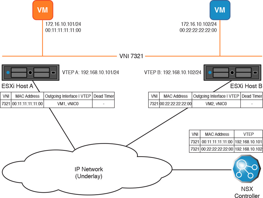
In Figure 5-10, two ESXi hosts with a logical switch in VNI 7321 have a powered on VM connected to VNI 7321. No communication has taken place in the previous five minutes between the VMs. Figure 5-10 shows three MAC tables for VNI 7321, one for each ESXi host (provided by the vDS) and the MAC table in the NSX Controller. The VNI MAC table of each ESXi host only contains the MAC entry for its VMs, whereas the MAC table at the NSX Controller has both MAC entries pointing to the VTEP where the MAC resides.
The NSX Controller’s MAC table does not have a dead timer. The NSX Controller depends on the ESXi hosts to keep it updated on the state changes of MAC addresses. The ESXi host does not keep a dead timer for MAC entries learned from the vmx file.
In case a VM connected to a logical switch vMotions, the source ESXi host notifies the NSX Controller that it no longer has the MAC entry in its MAC table. The NSX Controller then removes the MAC entry from its MAC table. At the completion of vMotion, the destination ESXi host does two things:
Notifies the same NSX Controller, since it is the NSX Controller responsible for the logical switch, that it has a new MAC address. The NSX Controller updates its MAC table to include the MAC address of the VM with the destination ESXi host as the destination VTEP.
This is a function of NSX. Following what we have learned thus far, the destination ESXi host tells the NSX Controller of newly added local MAC entries to its MAC table.
Sends a Reverse ARP, RARP, over the logical switch to let all other VTEPs know about the MAC address.
This is a function of vMotion. The destination ESXi host sends an ARP request, on behalf of the VM, over the Ethernet broadcast domains the VMs connect.
Remember that vMotion is a feature of vCenter and as such NSX does not factor in the decision if vMotion can take place or not. That said, there is an advantage of doing vMotion in a logical switch over doing vMotion in a standard or dvPortgroup. With the logical switch, we no longer have to worry about ensuring that the vMotion source and destination ESXi hosts have access to the same VLAN, over the underlay, to which the VM is connected.
If the logical switch receives traffic with a destination MAC address that is not in its MAC table, the ESXi host sends a request for the entry to the NSX Controller responsible for the VNI. If the NSX Controller has the MAC address in its MAC table, it sends a response back to the ESXi host. The ESXi host adds the entry to its MAC table (refer to Table 5-2) with a dead timer of about 200 seconds. We discuss in the “Replication Mode” section of this chapter what happens when the NSX Controller does not have the MAC entry or does not reply.
Quick summary of what ARP is and is used for: Whenever an operating system (OS) wants to communicate via IP with another entity in the same Ethernet broadcast domain, it needs to match the destination IP address to a MAC address. The ARP table is where the OS looks for the IP-MAC mapping. An IP can only have a MAC address associated with it in the ARP table. If the entry the OS is looking for is missing from the ARP table, the OS sends out an ARP request.
ARP requests have a destination address of FFFF.FFFF.FFFF, better known as a Layer 2 broadcast, or just broadcast. Broadcasts can be detrimental to any environment because they are received by every system with a connection in the same broadcast domain. One of the most common and regular Ethernet broadcast domains is an ARP request.
To provide some level of broadcast suppression, ESXi hosts maintain an ARP table, per ESXi host. The NSX Controller maintains a second ARP table per logical switch. Each ESXi host, per logical switch, populates the local ARP table by doing snooping on ARP replies and DHCP acknowledgements. If the ESXi host updates its ARP table for one of its directly connected VMs, it sends a copy of the entry to the NSX Controller. Two ESXi hosts with the same VNI will not synchronize ARP tables.
Little secret: The logical switch doesn’t actually keep an ARP table, as a logical switch is a Layer 2 entity and ARP tables are not really part of Layer 2 themselves. Instead, there is a fourth module, the Switch Security module (discussed briefly in Chapter 4), which maintains the ARP tables in the ESXi host. The logical switch and the Security module are really good friends and work exceptionally well together.
The ARP table has three fields:
VNI
MAC Address
IP Address
By having a VNI field, the ARP table provides support for duplicate IP subnets in different logical switches. Or in other words, NSX supports multitenancy. Figure 5-11 shows the ARP tables for two ESXi hosts with powered on VMs in VNI 7321. The VMs have not communicated with each other at this point. The Switch Security module of each ESXi host has provided the NSX Controller an update, called an IP report, for the ARP table.
Every time a VM sends an ARP request, it is processed by the Switch Security module to check the ARP table for a corresponding entry. If a match is found, the Switch Security module sends an ARP reply back to the requester and does not broadcast the ARP request. If a match is not found, the Switch Security module sends a request for the entry to the NSX Controller responsible for the VNI. We discuss in the “Replication Mode” section of this chapter what happens when the NSX Controller does not have the ARP entry or does not reply.
You can confirm that the NSX Controllers have their tables populated by connecting to the NSX Controllers via SSH or console. The administrator username for the NSX Controllers is admin, and the password is whatever you configured when you deployed the first NSX Controller.
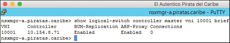
All NSX Controllers know which NSX Controller is responsible for a particular VNI. From any NSX Manager privilege CLI prompt, enter the command show logical-switch controller master vni X brief to see the NSX Controller responsible for the logical switch with VNI of X, as shown in Figure 5-12 for VNI 10001. VNI 10001 is the universal logical switch Universal App LS shown in Figure 5-2. From the NSX Controller CLI, which is case sensitive, the same output would be obtained with the command show control-cluster logical-switches vni X. In Figure 5-12, we connected to NSXMGR-A. The command output shows the responsible NSX Controller for VNI 10001 is 10.154.8.71. Note that the connections say 0. To see the actual number of connections, you need to type the ControllerID instead of master in the command. The ControllerID is obtained with the command show controller list all.
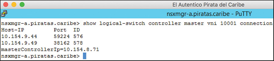
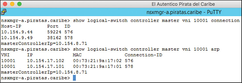
To view the principal tables in the NSX Controller using the NSX Controller CLI, we need to SSH or console in to the responsible NSX Controller. Once we are connected, we can execute our first command to confirm which ESXi hosts have powered up VMs in the VNI. The command is show control-cluster logical-switches connection-table X, where X is the VNI number. So we don’t have to bounce around NSX Controllers to view multiple VNIs, we can execute the CLI commands from any NSX Manager. The command to view the Connection table is show logical-switch controller master vni X connection. Figure 5-13 shows the output of the command for VNI 10001. The IPs you see are the IPs of the Management VMkernel port of each ESXi host. Host-IP 10.154.9.44 is the IP of an ESXi host in the Santo Domingo Data Center. Host-IP 10.154.9.49 is the IP of an ESXi host in the Tampa Data Center. Both hosts are in the VTEP table of the logical switch. The ID number is the locally significant, to the NSX Controller responsible for VNI 10001, Connection ID.
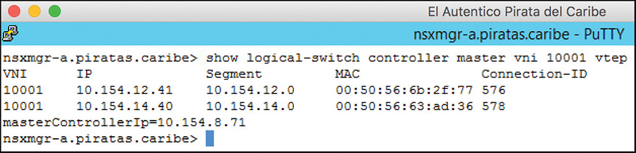
The next table we want to look at is the VTEP table. The NSX Manager command to see the VTEP table is show logical-switch controller master vni X vtep, where X is the VNI number. The equivalent NSX Controller command is show control-cluster logical-switches vtep-table X. Figure 5-14 shows the output of the NSX Manager command for VNI 10001. All the IPs and MACs we see are from the VXLAN VMkernel ports of the host from Figure 5-13. These VTEPs have at least one pinned VM powered on and connected to logical switch 10001.
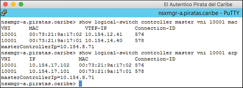
For the MAC and ARP tables, you can execute these NSX Manager commands (with the equivalent NSX Controller commands in parentheses), shown in Figure 5-15 for VNI 10001:
show logical-switch controller master vni X mac (show control-cluster
logical-switches mac-table X)
show logical-switch controller master vni X arp (show control-cluster
logical-switches arp-table X)
Now, about that ID number we saw in the Connection table! The ID number, the Connection ID, is assigned by the NSX Controller to match entries from other tables back to the management IP of the host. For example, if you want to know which ESXi host provided an ARP entry in the ARP table, simply match the Connection ID in the ARP entry with the connection ID in the ID number in the Connection table, as shown in Figure 5-16. The figure shows that the ESXi host with a Connection ID of 576 provided the ARP entry for IP 10.154.17.102. Cross-referencing the Connection ID in the Connection table tells us the ESXi host’s management IP is 10.154.9.45.
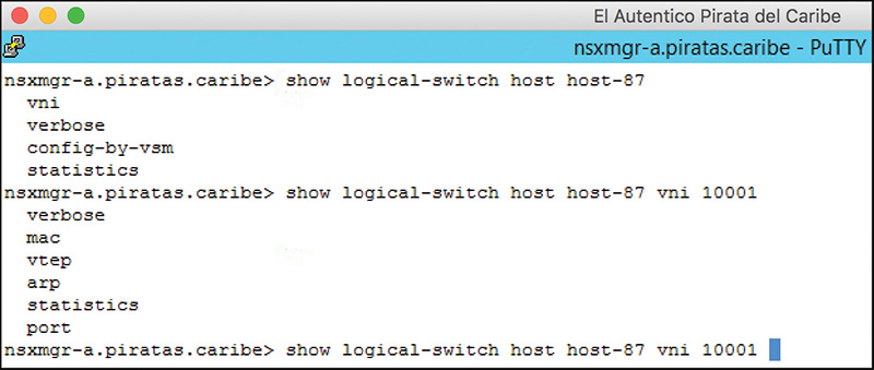
There are three additional commands that can be handy for troubleshooting that pull VNI information from the ESXi host. Figure 5-17 shows a list of the command options to pull information from the hosts local to the NSX Manager. To get the host-id, type the command show cluster cluster-id, where cluster-id is the cluster where the host belongs.
If a logical switch receives a frame from a VM with a destination MAC address that is not present in the local MAC table, the logical switch sends a query to the NSX Controller responsible for the VNI, using the ESXi host’s Management VMkernel port. The NSX Controller then replies back to the logical switch in the ESXi host with the MAC table entry. The logical switch then adds the MAC table entry with a dead timer of about 200 seconds and forwards the VM’s frame to the destination VTEP. If the logical switch processes any return traffic with the MAC address as the source before the dead timer expires, the dead timer is reset back to five minutes.
If an ARP request is received from a local VM and the ARP entry is not in the Security module’s ARP table, the Security module sends a query to the NSX Controller using the ESXi host’s Management VMkernel port. The NSX Controller then replies back to the Security module in the ESXi host with the ARP table entry. The Switch Security module adds the ARP entry to the ARP table and sends an ARP reply back to the VM that sent the ARP request.
The NSX Controller ARP table entries do not have a timeout. The NSX Controller depends on the ESXi hosts to keep it updated on the state changes of ARP entries.
Every time a logical switch receives a frame from a locally attached VM for which it does not have a MAC entry in its table or it is an ARP request for which the Security module does not have an entry in its ARP table, a request for the entry is sent to the NSX Controller responsible for the VNI. But what happens when any of these is true for the logical switch?
Receives broadcasts from locally connected VMs that are not an ARP request.
Receives multicasts from locally connected VMs that are not in the IGMP Snooping table. (IGMP Snooping is supported by the vDS in vSphere 6.0.)
The NSX Controller does not have the unknown unicast MAC address in its MAC table.
The NSX Controller does not have the ARP entry in its ARP table for the ARP request.
The NSX Controller is down or unavailable.
If any of these cases happen, the logical switch goes into Replication Mode. Replication Mode provides a mechanism to ensure that every host with a VM connected to the VNI receives a copy of the original frame. Remember that a logical switch has only a single VNI and vice versa, and that each ESXi host keeps its own local copy of the MAC and ARP tables per logical switch/VNI.
Think of Replication Mode as what a physical Ethernet switch does when it receives a Broadcast, Unknown unicast, or Multicast (BUM). When receiving a BUM, the physical Ethernet switch would either flood the frame (if it is an unknown unicast) or broadcast the frame (if it is a broadcast or multicast that is not in the IGMP Snooping table). In either case, every other physical Ethernet switch configured in the same broadcast domain as the BUM receives the BUM frame.
When dealing with physical Ethernet switches, it is simple to ensure that every other physical Ethernet switch receives a copy of the BUM: Simply replicate the BUM out of each interface of the physical Ethernet switch (except the interface the BUM arrived in) that is in the same Ethernet broadcast domain. But with logical switches we don’t have interfaces but rather tunnels, VXLAN overlays, which create a design challenge (or opportunity if you are the endless optimist):
Of all the other VTEPs in the NSX domain, which ones have VMs in the same VNI as the BUM, and thus need a copy of the frame?
The answer to the question can be found in the VTEP table. Take a minute to go back to earlier in the chapter and review the fields included in the VTEP table and what the NSX Controller does when it updates the VTEP table. I’ll wait.
Now that you are back, it should be clear that the VTEP table provides an accurate list of every VTEP that has at least one VM in the VNI. Because the NSX Controller responsible for the logical switch sends updated copies of the VTEP table to each ESXi host with a VTEP in the table, all VTEPs can execute Replication Mode even if the NSX Controller responsible for the logical switch is down.
For completeness, there is an alternative to solving the design challenge mentioned above that does not depend on the VTEP table, or leveraging the NSX Controller for that matter. That option involves using Multicast Replication Mode, and we review it in the next section.
There are three ways, or modes, in which the source ESXi host can replicate the frame so that all ESXi hosts with VMs in the same VNI get a copy. The three modes are
Multicast (This option does not leverage the VTEP table.)
Unicast
Hybrid
The Replication Mode the logical switch will use is selected when you create the transport zone. Alternatively, you can overwrite the Replication Mode, per logical switch, when you create the logical switch.
I mentioned earlier that VXLAN is an open standard supported by the big data center companies, such as VMware. The VXLAN standard does not include the role of a centralized controller, such as the NSX Controller. Therefore to solve the design challenge mentioned earlier, the VXLAN standard’s solution is to associate each VNI, or logical switch, with a multicast group address. Because there is no NSX Controller to query when there is BUM, each logical switch would default to replicating each and every BUM but encapsulating the BUM in a VXLAN frame with a destination IP address of the multicast group for the VNI. That last sentence was a mouthful; so let me rephrase it this way:
If the logical switch doesn’t have it in the MAC table or the vDS IGMP Snooping table, multicast it.
All VTEPs that receive the multicast VXLAN frame decapsulate the frame and send a copy of the BUM to each powered on VM connected to the logical switch. In the case the BUM is an unknown unicast, the VM that owns the destination MAC address of the BUM replies back to the VM that sent the BUM. When the logical switch in the ESXi host where the BUM originated from processes the response frame, it learns the MAC address of the VM that owns the unknown unicast MAC (and it will no longer be unknown). We review this process further in Chapter 6, “Logical Switch Packet Walks.”
For any logical switch configured with Multicast Replication Mode, the NSX Controller will not keep a VTEP table, a MAC table, or an ARP table.
During Segment ID configuration, where you provided NSX Manager with the pool of VNIs to use for logical switches, there is an option to enable multicast addressing. You need to select this option and provide the pool of multicast addresses if you plan to use Multicast Replication Mode.
If the pool of multicast groups is smaller than the pool of VNIs, then the NSX Manager maps multiple VNIs to the same multicast group address.
For Multicast Replication Mode to work, every VTEP that has at least one VM powered on has to join the multicast group so it can be a source and receiver for the multicast group. After the ESXi host is informed of the creation of a logical switch and the first VM in the logical switch powers up or vMotions to the ESXi host, the ESXi host sends an IGMP Join request, for the multicast group that was provided to it by NSX Manager, over the VXLAN VMkernel port, the VTEP. When the last VM in the VNI in the ESXi host powers off or vMotions from the ESXi host, the ESXi host sends an IGMP Leave request for the multicast group.
NSX VTEPs support IPv4 multicast. For Multicast Replication Mode to work, PIM (if VTEPs are in different subnets) and IGMP must be configured in the underlay.
One potential downside of using Multicast Replication Mode is that every single BUM is seen and processed by each ESXi host with powered on VMs in the VNI, and additional resources are consumed in the underlay to process all the multicast traffic. On the plus side, the source ESXi host sends only a single VXLAN frame for each BUM.
With Multicast Replication Mode, none of the VTEPs have a full list of all VTEPs that have powered on VMs in the logical switches. As mentioned earlier, the other alternative to the replication design challenge is to leverage the VTEP table to provide all VTEPs a full view of which VTEPs have running VMs in each VNI. With this full view of things, instead of multicasting whenever a frame needs to be replicated, the frame that needs to be replicated could be unicasted inside a VXLAN frame to each VTEP that is in the VTEP table for the VNI.
In Unicast Replication Mode, a frame will be replicated if any of the following is true for the logical switch:
Receives broadcasts from locally connected VMs that are not an ARP request.
Receives multicasts from locally connected VMs, and it is not in the IGMP Snooping table of the vDS.
The NSX Controller does not have a unicast MAC address in its MAC table (unknown unicast).
The NSX Controller does not have the ARP entry in its ARP table for the ARP request.
The NSX Controller is down or unavailable.
One immediate advantage to Unicast Replication Mode is a reduction in the number of frames that need to be replicated since the NSX Controller has the principal tables for MAC and ARP. Another advantage to Unicast Replication Mode is that it makes it unnecessary to enable IGMP or PIM in the underlay.
A disadvantage to Unicast Replication Mode is that if the VTEP table is large, the source VTEP might have to send many VXLAN frames, one per VTEP in the VTEP table. To reduce the impact of this disadvantage, the ESXi hosts use something called the Proxy VTEP field. The role of Proxy VTEP is to receive the BUM-replicated VXLAN frame from the source VTEP. The Proxy VTEP then sends a unicast copy of the BUM-replicated VXLAN frame to all VTEPs in its VTEP subnet. The source VTEP is still responsible to unicast the BUM-replicated VXLAN frame to all VTEPs in its local VTEP subnet. The proxy VTEP is selected at random from the VTEP table by the source ESXi host. The source ESXi host selects a proxy VTEP per VTEP subnet in the VTEP table.
How does the proxy VTEP know that it needs to replicate the VXLAN frame it just received? It knows because it sees that in the VXLAN flags field, the Replication bit is set to 1. The source VTEP sets the Replication bit to 1 before sending the VXLAN frame to the proxy VTEPs. Before the proxy VTEP replicates the VXLAN frame to the VTEPs in its VTEP segment, it resets the Replication bit back to 0.
Because the proxy VTEP is itself forwarding the replicated VXLAN frame via unicast, it is called a unicast proxy VTEP (UTEP).
Yes, Hybrid Replication Mode is the happy union of Unicast Replication Mode and Multicast Replication Mode. Hybrid Replication Mode leverages the NSX Controller for the principal tables of VTEP, MAC, and ARP. In Hybrid Replication Mode, a frame will be replicated if any of the following is true for the logical switch:
Receives broadcasts from locally connected VMs that are not an ARP request.
Receives multicasts from locally connected VMs, and it is not in the IGMP Snooping table of the vDS.
The NSX Controller does not have a unicast MAC address in its MAC table (unknown unicast).
The NSX Controller does not have the ARP entry in its ARP table for the ARP request.
The NSX Controller is down or unavailable.
With Unicast Replication Mode, you have the source VTEP and Proxy VTEPs sending unicast VXLAN frames to all VTEPs in their local VTEP subnets. With Hybrid Replication Mode, the source VTEP sends a single Multicast VXLAN frame to its local VTEP subnet while sending a single unicast VXLAN frame to the proxy VTEPs. The proxy VTEPs, upon receiving the unicast VXLAN frame with the Replication bit set to 1, then sends a single multicast VXLAN frame to their local VTEP subnet.
In Hybrid Replication Mode, the proxy VTEP is called multicast proxy VTEP (MTEP).
An advantage of Hybrid Replication Mode is that it can greatly reduce the number of replicated VXLAN frames the source VTEP needs to send. A potential disadvantage for Hybrid Replication Mode is that IGMP Querier and IGMP Snooping should be configured in the underlay for the local VTEP broadcast domains. If IGMP Snooping is not configured, the underlay Ethernet switch treats all replicated multicast VXLAN frames as broadcast.
Just as in Multicast Replication Mode, a multicast group is required for each VNI in Hybrid Replication Mode. Each VTEP that has a powered on VM connected to the VNI sends an IGMP Join for the multicast group assigned to the VNI. PIM is not required in the underlay to support Multicast Replication Mode. To prevent the replicated multicast VXLAN replicated frame from crossing Layer 2 boundaries, the Time to Live (TTL) in the multicast VXLAN frame’s IP header is set to 1.
Something that should be pointed out now, and I already mentioned for Multicast Replication Mode: All VTEPs receiving the replicated VXLAN frame decapsulate the frame and forward a copy of the BUM to all powered on virtual machines connected to the VNI. For any unknown unicast and ARP request not in the local ARP table, the source VTEP learns the MAC or ARP entry when the destination virtual machine responds. This is true for all three modes of replication. We see more of this in Chapter 6 when we discuss packet walks for logical switches.
Review the most important topics from inside the chapter, noted with the Key Topic icon in the outer margin of the page. Table 5-3 lists these key topics and the page numbers where each is found.
Download and print a copy of Appendix C, “Memory Tables” (found on the book’s website), or at least the section for this chapter, and complete the tables and lists from memory. Appendix D, “Memory Tables Answer Key,” also on the website, includes the completed tables and lists so you can check your work.
Define the following key terms from this chapter, and check your answers in the Glossary: