Objective 5.4—Configure and Manage Logical Routers
This chapter covers all or part of the following VCP6-NV exam blueprint topics:
Objective 5.4—Configure and Manage Logical Routers
Objective 9.5—Administer Logging
We have arrived at the chapter where we talk about how the NSX Edge and the logical router learn about routes for subnets not directly connected to them. There are many ways in physical networks for route information to be propagated. In the case of NSX, and its tendency to simplify the network, the features needed to advertise network reachability are less complex than what might be found in the physical network.
This chapter reviews the three routing protocols supported by NSX: OSPF, BGP, and IS-IS. The chapter also covers how to configure static routes and concludes with a configuration of route redistribution.
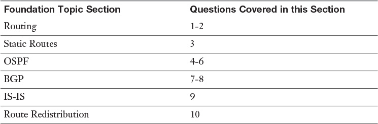
The “Do I Know This Already?” quiz allows you to assess whether you should read this entire chapter or simply jump to the “Exam Preparation Tasks” section for review. If you are in doubt, read the entire chapter. Table 12-1 outlines the major headings in this chapter and the corresponding “Do I Know This Already?” quiz questions. You can find the answers in Appendix A, “Answers to the ‘Do I Know This Already?’ Quizzes.”
1. Which routing protocol is not supported by a logical router?
a. Static
b. BGP
c. IS-IS
d. OSPFv2
2. Which routing protocol is not supported by an NSX Edge?
a. OSPFv2
b. BGP
c. IS-IS
d. OSPFv3
3. After configuring a static route, how long would the Control VM retain it before flushing it from the routing table?
a. 10 minutes
b. 24 hours
c. 72 hours
d. Permanently
4. Which OSPF authentication mechanism does the logical router not support?
a. MD5
b. SHA
c. Cleartext
d. None
5. Which OSPF area is not supported by the NSX Edge if configured as an ABR?
a. Backbone area
b. Normal area
c. Stubby area
d. Not So Stubby area
6. An NSX Edge is configured as an ABR. The Edge has a non-backbone interface link in the same segment as a logical router. Which Link State Advertisement Type is not received by the logical router from the NSX Edge?
a. LSA Type 1
b. LSA Type 2
c. LSA Type 3
d. LSA Type 7
7. A Perimeter Edge is being configured to run iBGP with a logical router. What BGP Neighbor IP address should be configured in the Perimeter Edge for the BGP Peers to come up?
a. The IP of the Uplink interface in the Control VM.
b. The forwarding IP configured in the logical router.
c. The protocol IP configured in the Control VM.
d. The management IP of the logical router.
8. Which of the following commands can be used to check the BGP route table?
a. show ip route bgp
b. show ip bgp
c. show ip bgp route
d. debug ip bgp
9. How many IS-IS areas can be configured in the NSX Edge?
a. 1
b. 2
c. 3
d. 10
10. What OSPF metric type is assigned to routes redistributed into OSPF by a universal logical router?
a. Intra-Area
b. Inter-Area
c. External Type 1
d. External Type 2
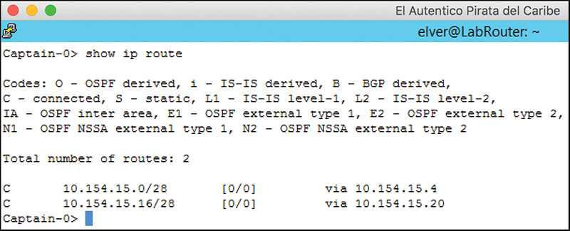
Let’s start by talking about how the logical router and the NSX Edge populate their routing tables. The routing table contains the destination path information the logical router and the NSX Edge use when deciding the egress interface for forwarding packets. The routing table contains a list of routes. A route is defined as a subnet/subnet mask pair, administrative distance and cost, and the next hop. We discuss the administrative distance and cost in the “Administrative Distance and Cost” section that follows. The next hop is defined as an entity that should know how to get traffic delivered to the destination. The subnets and subnet masks configured in the interfaces of the routers, also referred to as directly connected, get added by default to the routing table of the logical router and NSX Edge, with the router’s interface IP as the next hop. Any other subnet and subnet mask not configured in the interface of the router will have a next hop. The routing entries of NSX Edges for directly connected subnets look similar to Figure 12-1.
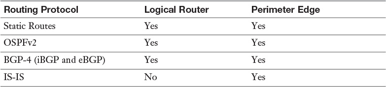
Both the logical router and NSX Edge Gateway support routing protocols. By saying the logical router supports a routing protocol, it is implied that the protocol runs in the logical router Control VM. If the logical router and the NSX Edge form a routing adjacency, the Edge would be exchanging routing information with the Control VM. You should always consider placing the Control VM in the same cluster as the NSX Edge that it is exchanging routing information with. Table 12-2 shows the protocols supported by each router.
When the logical router or the NSX Edge receives a packet, it reads the destination IP of the packet and finds the most specific subnet and subnet mask match in the routing table for the IP. For example, assume the router has two interfaces with IPs of 192.168.1.2 and 192.168.2.1 and the following four routing entries in the routing table:
10.10.0.0/16, via 172.16.1.1
10.10.0.0/24, via 192.168.1.1
192.168.1.0/24, via 192.168.1.2
192.168.2.0/24, via 192.168.2.1
If a packet arrives with a destination IP of 10.10.0.4, the next hop is 192.168.1.1 because it has the most specific route to the destination with a subnet mask of /24. Another thing the routers would do is recursive routing. In our example, the destination IP of 10.10.0.4 has a next hop of 192.168.1.1. The router then does another routing lookup, hence the recursive routing, for 192.168.1.1. The router continues doing routing lookups for the next hops in the routing table until it finds the next hop to be the IP of one of its interfaces. For the lookup for IP 192.16.1.1, the next hop for 10.10.0.4, the router turns up the following entry in the routing table:
192.168.1.0/24, via 192.168.1.2 <- IP of router's interface
The router stops the recursive routing lookup and sends an ARP request for 192.168.1.1’s MAC address.
A router can add routing table entries learned by different methods and protocols. Assume a router has a routing table with the following two entries:
B 192.168.1.0/24, via 172.16.1.1
C 192.168.1.0/24, via 192.168.1.1
The router has two routing entries to the same destination but with different gateways. The first entry is learned via BGP and the second entry is directly connected to the router. The question the router needs to ask itself is “which of the two entries should I use?” You would be wrong if you suggest we use ECMP, although you may be forgiven for it. The best path for a directly connected subnet will always be the router’s interface connected to that subnet. There is no way that selecting the BGP learned path over the directly connected path would be better in this case (or any case). The same would be true if the first routing entry was a static or OSPF learned route.
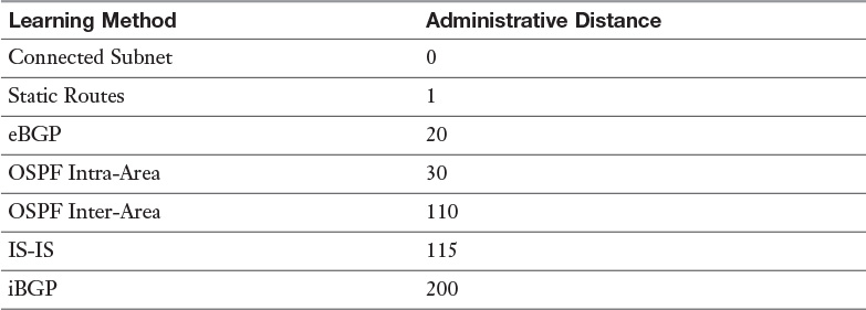
When the router has multiple paths to the same destination, however, those paths are learned via different methods or routing protocols. The router must make a decision as to which of those paths is the most reliable and only add that path to the routing table. To do so, the router assigns a value to each method or protocol, with the lowest number viewed as more reliable. That number is called the administrative distance. Table 12-3 shows the default administrative distance of the different learning methods and routing protocols.

Administrative distance only matters to the router if two different learning methods or routing protocols have a path to the same subnet.
In our routing table example, there would be one entry for subnet 192.168.1.0/24, which would appear in the routing table as:
C 192.168.1.0/24 [0/0] via 192.168.1.2
The first 0 in the brackets represents the administrative distance. The second 0 represents the cost to reach the destination. Cost is a value assigned by the learning method or routing protocol to differentiate which is the best path to a destination. If a learning method or routing protocol with the lowest administrative distance knows of multiple paths to the same destination, the router only adds to the routing table the path with the lowest cost. Each routing protocol uses its own algorithm to calculate cost.
Some routing protocols use metric instead of cost. The application and goal are the same.
Only directly connected routes would have a cost of 0.
ECMP only works for multiple paths to the same destination that have the same cost.
Static routes are manual entries to the routing table. Static routes are easy to implement and once created they are permanent until someone removes them. Static routes do not lend themselves to be flexible in accounting for network changes, which makes them inadequate in many situations. On the upside, static routes do not consume a lot of the router resources, which makes them ideal for smaller scale routers at the edge of the network. Routers at the edge of the network are also called spokes or stubs. Logical routers are almost always deployed as stubs, and in an NSX environment with a well-planned IP addressing scheme, the Perimeter Edge can be viewed as a stub by the physical network.
Both the logical router and the NSX Edge support static routes. The process to configure a static route is almost identical for both the logical router and the NSX Edge. To create a static route (with the exception of a default route), follow these steps:
Step 1. From the NSX Edges view, select the NSX Manager that owns the Control VM or NSX Edge and double-click the logical router or NSX Edge that is getting the static route.
Step 2. Go to Manage > Routing and select Static Routes.
Step 3. Click the green + icon and wait for the Add Static Routes Wizard to come up.
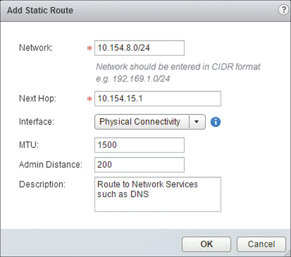
Step 4. Complete the following fields:
Network: The subnet for the static route. It should be in the format X.X.X.X/YY, where YY is the subnet mask.
Next Hop: Enter the IP of the next hop. You can enter multiple IPs as next hop if you have enabled ECMP.
Interface: The outgoing interface for the static route.
MTU: You can change the configured MTU of the interface for traffic going to the subnet identified in the Network field. The MTU must be less than or equal to the MTU configured in the interface.
Admin Distance: The administrative distance for this route. This value is also used as the cost.
Locale ID: This is applicable to universal logical routers only. Enter the Locale ID for this route. Only ESXi hosts with matching Locale ID get this static route.
Description: This field is optional.
Your configuration should look similar to the one in Figure 12-2. Click OK.
Step 5. Click Publish Changes.
The default route is created in a different place, the Global Configuration page. The process is also identical for both the logical router and the NSX Edge. To create a default route, follow these steps.
Step 1. From Manage > Routing select Global Configuration.
Step 2. Click Edit in the Default Gateway field.
Step 3. Wait for the Edit Default Gateway Wizard to come up.
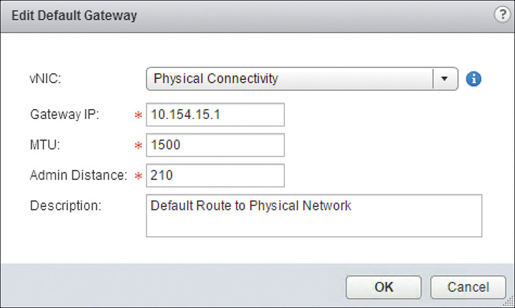
Step 4. Complete the following fields:
Interface or vNIC: The outgoing interface where the default gateway can be found. The logical router has an Interface option; the NSX Edge has a vNIC option.
Gateway IP: The IP of the default gateway.
MTU: You can change the configured MTU of the interface for traffic going to the default gateway. The MTU must be less than or equal to the MTU configured in the interface.
Admin Distance: The administrative distance for this route. This value also is used as the cost.
LocaleID: This is applicable to universal logical routers only (not shown in Figure 12-3). Enter the Locale ID for this route. Only ESXi hosts with matching Locale ID get this static route.
Description: This field is optional.
Your configuration should look similar to the one in Figure 12-3. Click OK.
We could jump right in and start configuring OSPF in the logical router and the Edge, but I would be doing you a disservice if I did. There is no point in configuring OSPF without understanding the OSPF basics. For that reason, we spend some pages going over the foundations of OSPF and the features supported by the logical router and the Edge, followed by how to configure OSPF in NSX.
Open Shortest Path First (OSPF) is an open standard Interior Gateway Protocol (IGP) that uses the state of the routers’ links to determine a loop-free path to an IP destination. The OSPF protocol has its own transport, and IP Protocol 89 identifies it. An IGP is a routing protocol fully administered by the same organization or Autonomous System (AS). This means that all routing policies for an IGP are made and implemented by the same entity.
A link state is the status of an OSPF configured interface of the OSPF router. Some of the information included in the link state of the interface includes
The IP of the interface
The subnet mask of the interface
The cost of the interface
The speed is advertised as a cost that gets assigned to the interface. The cost is determined by dividing 10 gig by the interface speed.
A 10-Gbps interface has a cost of 1.
A 1-Gbps interface has a cost of 10.
The type of interface
OSPF is architectured to work in areas. Every interface in the router configured for OSPF must be in a single area. The OSPF router can have interfaces in multiple areas. OSPF routers then share the link state of their interfaces in the area with other routers in the area. An area is identified by a number from 0 through 232. If the OSPF AS has a single area, then the area number could be any number in the range 0 through 232.
Note
Intra-area means entities or things within the same area, such as traffic within the same area. Inter-rea means entities or things in different areas.
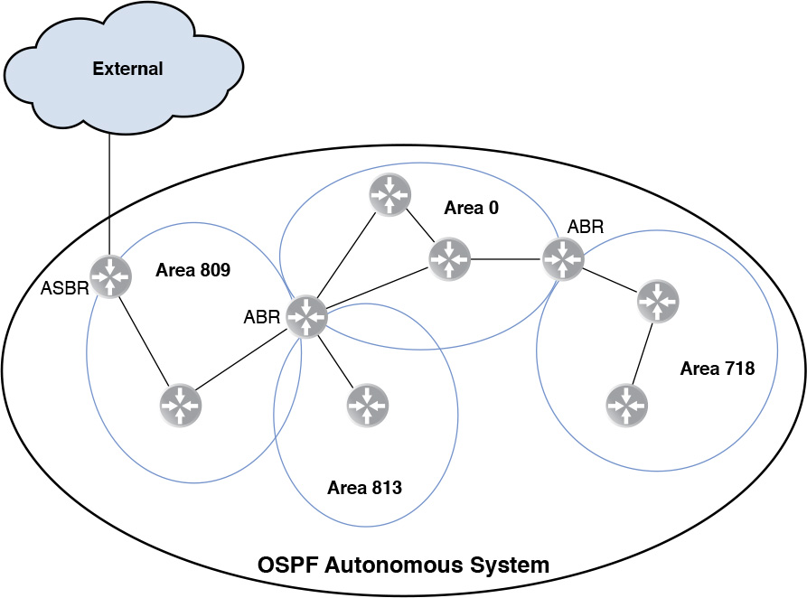
If there are two or more areas in the OSPF AS, one of those areas must be Area 0, also called the backbone area. All other areas in a multi-area OSPF domain must have at least one router with an interface in the backbone. All intra-area traffic must go through the backbone, and two areas can’t have the same router connected to each of them unless that router also has an interface in the backbone. A router that has a connection to the backbone and another area is called an area border router (ABR). There is another type of router that redistributes routes into OSPF from another routing process, static routes, or directly connected interfaces. This router is called Autonomous System Border Router (ASBR). An ASBR may or may not have an interface in the backbone area, and all routes redistributed by the ASBR from other routing processes, static routes, or directly connected interfaces are advertised by OSPF as if originating from the ASBR.
Route redistribution is the process of injecting routes to a routing process. The source of the routes could be a static route, another routing process, or directly connected interfaces. Redistributing a directly connected interface’s subnet into a routing process is not the same as adding the interface, and its subnet, into the routing process. When redistributing a route, the receiving routing process has no visibility into the true origin of the route. We configure route redistribution at the end of this chapter.
When configuring OSPF in the logical router, the logical router almost always is an ASBR. The logical router’s internal interfaces can’t participate in a routing process, so the only way to get the internal interfaces’ subnets advertised by OSPF is to redistribute the ASBR connected interfaces.
Figure 12-4 shows four areas, including the backbone area, an ASBR router, and two ABR routers, one of which has connections to three different areas. Intra-area traffic must stay within the area. Inter-area traffic from any non-backbone area must go thru the ABR and the backbone to reach another area.
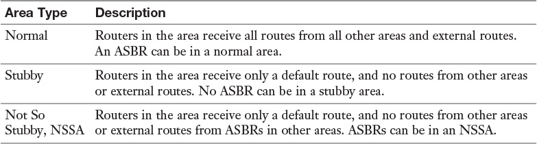
There are three types of areas. Table 12-4 shows the different OSPF areas and their definitions.
The logical router and NSX Edge support normal and NSSA areas. If acting as an ABR, the NSX Edge does not support stubby areas; however, both the logical router and the NSX Edge can be members of a stubby area.
OSPF neighbors exchange routing information by forming adjacencies with OSPF peers, and they only exchange link states with their neighbors if an adjacency has been formed. Link states are used to form the Link State Data Base (LSDB). The LSDB is used by the OSPF router to create a routing table by calculating the shortest path for each network in the LSDB. The shortest path is calculated using an algorithm derived from the Dijkstra’s algorithm. Once the shortest path is calculated for each network, an entry is added in the routing table with a cost for the route and the IP of the next hop in the calculated path.
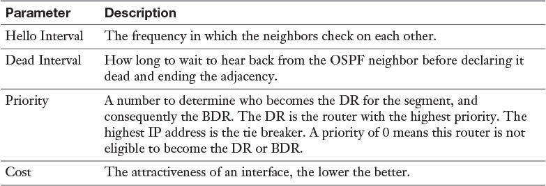
For an OSPF adjacency to be formed there has to be a Neighbor Discovery process first. The Neighbor Discovery process involves the exchange of some parameters with other OSPF routers via a series of multicast and unicast OSPF packets. During these exchanges, some parameters are verified to match between the neighbors. If the parameters don’t match, the neighbors won’t form an adjacency. Table 12-5 shows some of the parameters exchanged during Neighbor Discovery.
Another parameter exchanged between two OSPF routers while forming an adjacency is the MTU, although it can be disabled in the configurations of the logical router and the NSX Edge. If the MTU of both routers do not match, the OSPF adjacency won’t be formed.
One OSPF requirement is that all intra-area routers have the same LSDB. OSPF routers forward link states received from their neighbors to ensure every router in the OSPF area has the same LSDB. To minimize the number of neighbors that an OSPF router needs to form in a broadcast domain, two routers are designated to be the only ones that become neighbors with everyone else in the broadcast domain. Those routers are the Designated Router (DR) and the Backup Designated Router (BDR).
The DR is responsible for collecting all the link state advertisements from everyone in the broadcast domain and floods them out to everyone in the broadcast domain. The BDR has the same neighbor adjacencies as the DR, but it monitors the DR, and when the DR goes down, the BDR becomes the DR.
To provide a level of security and authentication for OSPF neighbors, NSX supports two forms of authentication, besides the None option:
Password
MD5
OSPF routers will not become neighbors nor exchange LSAs unless they authenticate each other. With password authentication, the password is sent cleartext. MD5 authentication is considered more secure because the password is never exchanged between the OSPF routers. Instead, a hash is created from the password and exchanged.
Each OSPF router sends out its link state via packets called Link State Advertisements (LSA). LSAs are sent out when the router gets a new neighbor, when a change occurs in one of the links, or after a certain period of network stability when the LSA ages out. If there are no network changes, LSAs are not sent out frequently.
Each router in the OSPF AS has a unique OSPF Router ID, which it uses to tag each subnet and the link state of each interface the routers advertise in LSAs. The OSPF Router ID is an IP that is unique among the OSPF routers in the OSPF AS. It is typical to use the IP of an interface as the OSPF Router ID.
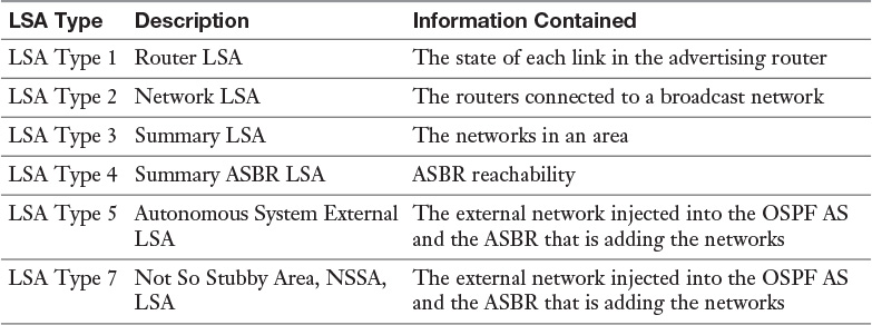
LSAs are classified by types, and each type carries different information, as shown in Table 12-6.
All routers send out Type 1 LSAs, which are flooded throughout the area, and the DR sends out Type 2 LSAs. All intra-area routers in the area get everyone else’s Type 1 LSAs. Type 1 and Type 2 LSAs are never sent outside the area. Type 3 LSAs are generated by ABRs and sent over the backbone area to provide a list of all the subnets from an area. Type 3 LSAs always have the ABR’s OSPF Router ID as the owning router of the subnet.
Type 4 LSAs are sent out by the ABR to provide information outside the area in how to reach the ASBR. Type 5 and Type 7 LSAs are originated by the ASBR. Type 5 LSAs are only found in a normal area and are forwarded to other areas by the ABRs. Type 7 is found only in NSSA areas and is turned into a Type 5 LSA by the NSSA ABR before being forwarded to the backbone area.
Routers in a broadcast domain send their LSAs to multicast address 224.0.0.6, which the DR and BDR listen to. The DR forwards all updates to multicast address 224.0.0.5, which all OSPF routers in the broadcast segment listen to. In NSX all OSPF segments are broadcast segments.
To configure OSPF in the logical router or NSX Edge follow these steps:
Step 1. From the NSX Home page click NSX Edges.
Step 2. Select the NSX Manager that owns the Control VM or NSX Edge and double-click the logical router or NSX Edge.
Step 3. Go to Manage > Routing and select Global Configuration.
Step 4. Click Edit in the Dynamic Routing Configuration Field.
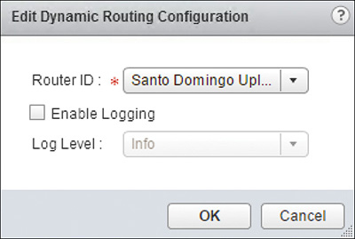
Step 5. In the Edit Dynamic Routing Configuration Wizard that opens up, complete the following fields:
Router ID: Select an Uplink interface to use for the OSPF Router ID. Optionally, select Custom and enter an IP address that is unique in the OSPF AS. The primary IP of the Uplink interface is the one used as the OSPF Router ID.
Enable Logging: Check the box if you want to enable logging of routing events.
Log Level: Select the logging level desired.
The configuration should be similar to Figure 12-5. Click OK.
Step 6. Click Publish Changes.
Step 7. Select OSPF.
Step 8. In OSPF Configuration, click Edit and complete the following fields in the OSPF Configuration Wizard:
Enable OSPF: Check the box to enable OSPF.
Protocol Address: This is Applicable to the logical router only. Enter the IP to assign the Control VM to use for OSPF Control Plane communication. This IP should be from the uplink segment.
Forwarding Address: This is Applicable to the logical router only. Enter the IP of the Uplink LIF. This IP is used to forward traffic in the data plane by the OSPF neighbors (Type 1 LSA).
Enable Graceful Restart: Check the box to enable Graceful Restart. With Graceful Restart enabled, the Control VM and NSX Edge notify their neighbors that the OSPF process is restarting and not to drop the neighbor adjacency. As a consequence, data plane traffic continues to flow, and the logical router and NSX Edge can resume OSPF control plane quicker.
Enable Default Originate: Check the box to send a default route to the OSPF neighbors. Make sure you fully understand what you are doing before turning this feature on.
Step 9. Click OK.
Step 10. Under Area Definitions click the green + icon to add an area. Two default areas are available—the Backbone Area and Area 51. You can delete these if you are not going to use them.
Step 11. In the New Area Definition Wizard that opens up, complete the following fields:
Area ID: The Area number.
Type: Choose the area to be Normal or NSSA.
Authentication: Choose between None, Password, and MD5.
Value: If selecting an authentication, enter the password. This password should be the same for all routers in the Area.
Click OK.
Repeat Step 11 for any additional areas.
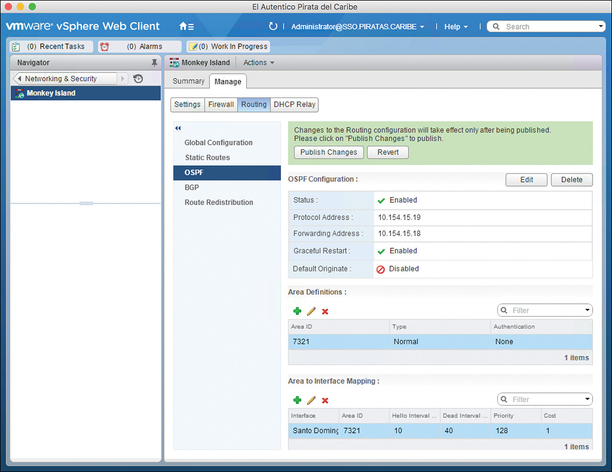
Step 12. Under Area Interface Mapping click the green + icon to add an interface to an OSPF area.
Step 13. In the New Area Interface Mapping that opens up, complete the following fields:
Interface or vNIC: Select the interface to add to the OSPF Area.
Neighbor discovery runs in this interface.
The network in this interface is added to the LSDB and sent out in Type 1 LSAs.
Area: The OSPF area to place the interface.
Ignore Interface MTU Setting: Check this box if you don’t want MTU verification to be done during Neighbor Discovery. Be warned that if two routers have MTU mismatch some packets will be dropped.
In the Advanced drop-down menu you can edit the parameters exchanged during Neighbor Discovery. You can edit these settings from their default values:
Hello Interval: Default value is 10 seconds. This value must match with the neighbor.
Dead Interval: Default value is 40 seconds. This value must match with the neighbor.
Priority: Default value is 128.
Cost: Default Value is 1; the OSPF routing cost for this interface. This value must match with the neighbor.
Click OK.
Repeat step 13 for any additional interfaces.
The configuration should be similar to Figure 12-6.
Step 14. Click Publish Changes.
Remember that the Control VM is the one that handles the Neighbor Discovery, exchanging the OSPF Hello packets with the OSPF adjacencies on behalf of the logical router. In the case of the ULR, you may have multiple Control VMs participating in OSPF. Unless you have strong reasons for doing so, you shouldn’t allow these Control VMs to be in the same OSPF area. The Control VM needs an IP, the Protocol IP, in the same subnet as the Uplink interface that will be configured for OSPF. Yes, I said the Uplink interface because the Control VM supports OSPF only over a single Uplink interface and only a single routing protocol at a time. For the ULR, each Control VM has OSPF configured in different Uplink interfaces.
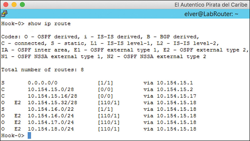
The best way to verify OSPF is working is to confirm networks are being advertised over OSPF. I (well, NSX, actually) cheated a bit and added some networks to OSPF to get the show IP route output in the Perimeter Edge shown in Figure 12-7 (you can also use the command show IP route OSPF to see only OSPF routes). By default, the logical router redistributes connected interfaces into OSPF when you enable it. We cover route redistribution later in this chapter.
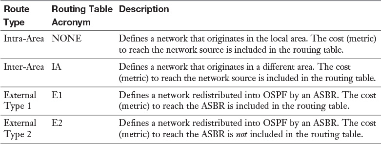
In Figure 12-7, you can see the type of OSPF route that each subnet represents. OSPF has four different types of routes that can be expressed in the routing table. Table 12-7 lists the four different OSPF route types and their definitions.
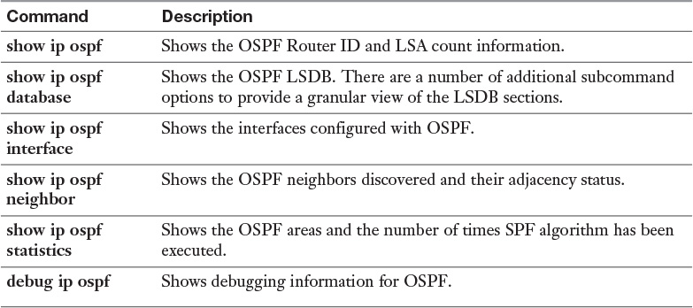
If you don’t see the routes you expect or you do not see OSPF routes at all, you can run one of the commands in Table 12-8 to verify OSPF functionality:
Border Gateway Protocol (BGP), is the de facto routing protocol of the Internet, with a primary goal of avoiding routing loops while exchanging network reachability information. BGP is an External Gateway Protocol (EGP). An EGP differs from an IGP in that multiple autonomous systems may manage an EGP. To differentiate BGP instances managed by different autonomous systems, an Autonomous System Number (ASN) is assigned to each BGP instance. An ASN must be globally unique. The Internet Assigned Numbers Authority (IANA) is the entity responsible for the maintenance and distribution of BGP ASNs.
BGP ASNs originally consisted of the numbers 1 through 65,534 (216 -2), with numbers 64,512 through 65,534 reserved for private use. ASNs 0 and 65,535 are reserved and should not be used by anyone. Private ASNs are not allowed in the Internet. NSX supports ASNs from 1 through 65,534.
BGP does not do Neighbor Discovery like OSPF. Instead, an administrator must tell the router whom its BGP neighbors, called BGP peers or just peers, should be. The BGP router would then send a series of handshake packets over TCP port 179. This makes BGP unique among routing protocols in that BGP peers do not have to have a connection to the same subnet; they could be worlds apart and still be BGP peers. In the cases where BGP peers are not directly connected to the same subnet, an IGP or static route is needed for the BGP peers to reach each other. BGP supports MD5 authentication to ensure the BGP is exchanging handshake packets with the correct BGP router. Once BGP peers are established, routes are exchanged among them.
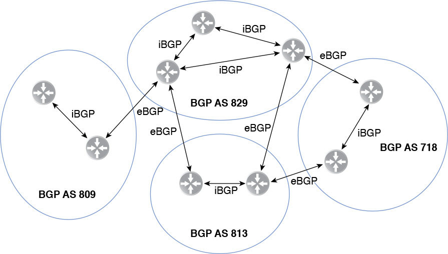
BGP makes a distinction in the types of peers it has based on whether the peers are in the same ASN. If the peers are in the same ASN, they are considered internal BGP peers or iBGP. If the peers are in different ASNs, they are considered external BGP peers or eBGP. iBGP and eBGP have slightly different rules for advertising routes and adding routes to the routing table. Figure 12-8 shows a number of ASNs with eBGP and iBGP peers.
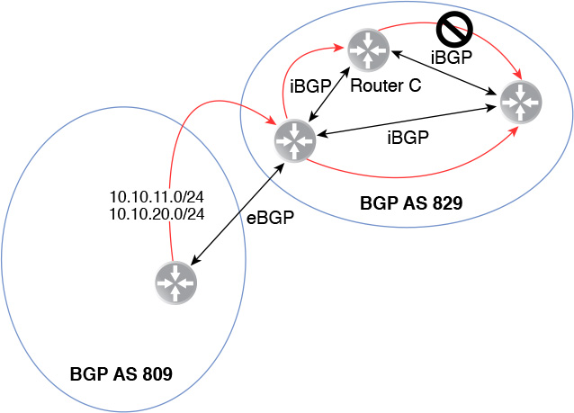
iBGP peers exchange routes by assuming that all iBGP peers are peers with all other iBGP peers. Stated in another way, iBGP is expected to be fully meshed. Because of the full mesh requirement, a BGP router shares a route with an iBGP peer only if the following conditions are met:
The iBGP peer received the route from an eBGP peer.
The iBGP peer is injecting the route into BGP.
Figure 12-9 shows iBGP peers in AS 829 learning about routes 10.10.11.0/24 and 10.10.20.0/24. The routes are injected into AS 829 from AS 809. Router C learns about the routes from the iBGP peer injecting the routes into AS 829, but Router C will not forward the routes to any iBGP peers.
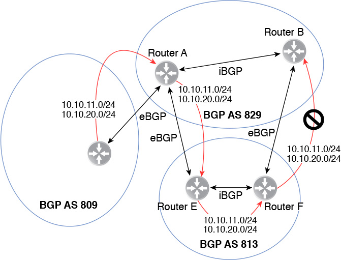
BGP advertisements have a field called the AS_PATH. When a route is advertised from one ASN to another, the ASN of the advertising eBGP router is added to the AS_PATH of the route. By default, BGP routers advertise all their routes to all their eBGP peers while following these three rules:
1. Add the advertising eBGP peer’s ASN to the AS_PATH of the route before advertising the route.
2. Never send a route to an eBGP peer if the peer’s ASN is already in the AS_PATH.
3. There is an IGP entry in the routing table for the advertised route.
The first two rules are critical in achieving BGP’s primary goal: to avoid loops. By adding the ASN to the AS_PATH of the route, each route has an accurate list of every ASN that needs to be crossed to reach the destination. This rule is needed to avoid sending a route back to an ASN that is in the AS_PATH for the route.
In OSPF, a router can have multiple interfaces added to OSPF in different OSPF areas. BGP does not have interfaces added to it. It is the whole router that gets placed in a BGP ASN, and a router can belong to only a single ASN. BGP has networks injected to it, either manually, by redistribution, or route summarization. If an administrator manually injects a network into BGP or redistributes it from a non-EGP routing protocol, IGP is considered the route origin for that network. If the route is redistributed from an EGP routing protocol, the route origin is considered EGP. If the administrator uses route summarization to inject the network into BGP, then BGP lists the origin of the network as unknown. The first entry in the AS_PATH field is always the route origin, followed by the ASNs.
Figure 12-10 shows eBGP peers exchanging routes for network 10.10.11.0/24 and 10.10.20.0/24, which originates in ASN 809. Router F will not forward the route 10.10.11.0/24 or 10.10.20/24 to Router B because Router B is in an ASN that is already in the AS_PATH of both 10.10.11.0/24 and 10.10.20.0/24.
The third BGP route advertisement rule is called synchronization. The rule of synchronization says that a BGP router may advertise a route to an eBGP peer only if there is an entry in the routing table for the route. The entry in the routing table could be from OSPF, IS-IS, a static route, or a directly connected subnet.
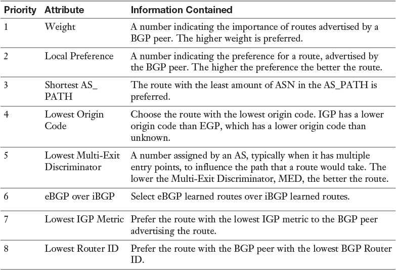
The number one priority of BGP is to avoid loops among the different ASNs. To avoid the loops, BGP does not natively support ECMP. A BGP router might receive the same route from multiple BGP peers, but it always selects one and only one route to each destination for inclusion to the routing table. BGP follows a straightforward algorithm to determine which route it adds to the routing table. The algorithm is called BGP Best Path Selection. Table 12-9 lists the BGP Best Path Selection attributes and their priorities. If two routes have a matching attribute, the algorithm proceeds down to the next priority attribute. Once a tiebreaker is found, that best route is added to the routing table.
With ECMP enabled, the logical router and the NSX Edge do add multiple BGP paths to the same destination in the routing table.
To configure BGP in the NSX Edge follow these steps:
Step 1. From the NSX Home page click NSX Edges.
Step 2. Select the NSX Manager that owns the Control VM or NSX Edge and double-click the logical router or NSX Edge.
Step 3. Go to Manage > Routing and select BGP.
Step 4. Click Edit and wait for the Edit BGP Configuration Wizard to pop up.
Enable BGP: Check the box to enable BGP.
Enable Graceful Restart: Check the box to enable Graceful Restart. With Graceful Restart enabled, the Control VM and NSX Edge notify their BGP peers that the BGP process is restarting and not to drop the BGP peering. As a consequence, data plane traffic continues to flow, and the logical router and NSX Edge can resume the BGP control plane quicker.
Enable Default Originate: Check the box to send a default route to the BGP peers. Make sure you fully understand what you are doing before turning this feature on.
Local AS: Enter the ASN for this router.
Step 5. Click OK.
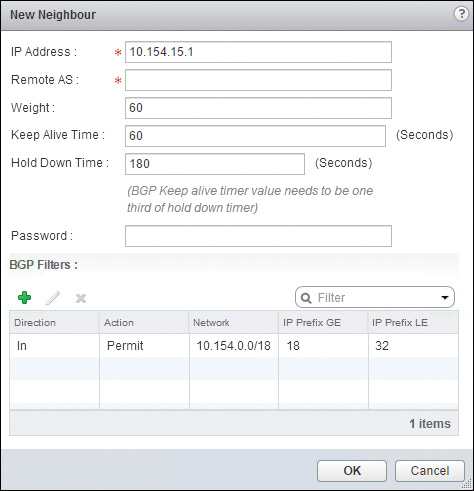
Step 6. In Neighbors click the green + icon and wait for the New Neighbor Wizard to pop up.
Step 7. Complete the following fields:
IP Address: The IP Address of the BGP Neighbor.
Forwarding Address: This is applicable to the logical router only. Enter the IP of the Uplink LIF. This is the IP used to forward traffic in the data plane by the BGP neighbors.
Protocol Address: This is applicable to the logical router only. Enter the IP to assign the Control VM to use for BGP control plane communication. This IP should be from the uplink segment.
Remote AS: The ASN of the BGP neighbor.
Weight: Enter the weight. You can enter 0 to ignore the weight.
Keep Alive Timer: The frequency in seconds of the hello packets.
Hold Down Timer: The amount of seconds to wait without receiving hellos from the BGP peer before removing all routes advertised by it from the routing table.
Password: Enter the password if MD5 authentication is required. This password must match at the BGP neighbor.
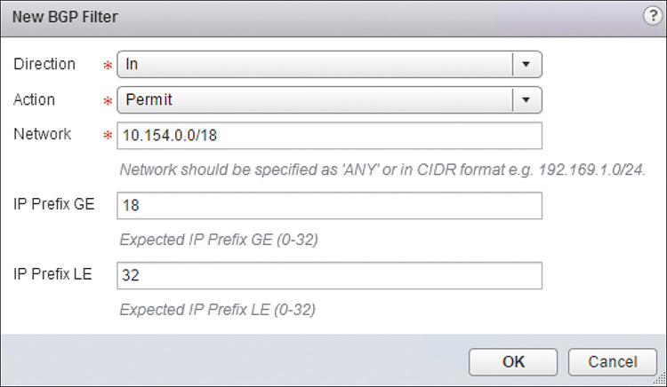
Step 8. If you want to filter the networks advertised to the BGP peer or received from it, click the green + icon under BGP Filters and enter the following values:
Direction: The direction of the route update the filter will be applied.
Action: Allow (Permit) or drop (Deny) the route.
Network: The subnet to filter and the subnet prefix to match.
IP Prefix GE: The subnet prefix to match. Any prefix greater than or equal to the prefix entered here matches the filter.
IP Prefix LE: The subnet prefix to match. Any prefix less than or equal to the prefix entered here matches the filter. To match only a single prefix, do not fill in the IP Prefix GE and IP Prefix LE fields.
The New BGP Filter configuration should look similar to Figure 12-11. Click Save.
Step 9. Repeat step 8 for additional subnets that should be filtered.
The New Neighbor configuration should look similar to Figure 12-12. Click Save.
Step 10. Click Publish Changes.
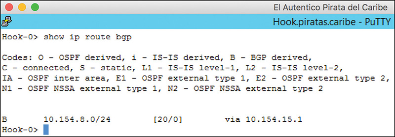
By now you should know that my recommendation is to check the routing table to make sure we are seeing BGP routes. Figure 12-13 shows the output of the command show ip route bgp.
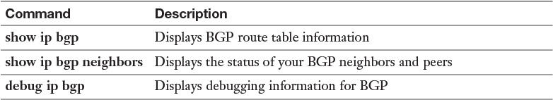
Table 12-10 has a list of commands that can be used to check the status of your BGP peers and BGP table.
Interior System to Interior System (IS-IS) is an open standard IGP that exchanges link states with its neighbors like OSPF. IS-IS is similar to OSPF in that it has areas, designated routers, uses the Dijkstra’s algorithm to calculate the shortest path to a network, maintains an LSDB, and can be configured with MD5 authentication. However, there are some differences between the two protocols that are worth mentioning before we move to configuring IS-IS in the NSX Edge. The logical router does not support IS-IS.
IS-IS is not part of the TCP/IP stack. IS-IS is a protocol of Connectionless-mode Network Service, CLNS, that resides in Layer 2 of the OSI model. IS-IS is designed to be independent of the protocol for which it is carrying routing information. This makes IS-IS flexible to carry routing information for non-CLNS protocols, such as IPv4, IPv6, and Transparent Interconnection of Lots of Links (TRILL) without having to update the IS-IS standard itself.
An IS-IS domain is equivalent to the OSPF AS. In IS-IS every router has to have a 6-byte System ID, which must be unique in the IS-IS domain. The System ID is analogous to an OSPF Router ID. IS-IS places the entire router in an area rather than the router’s interfaces, like OSFP does. An IS-IS area must be between 1 byte and 13 bytes in length expressed in hexadecimal. A router can be in multiple areas, and any two areas can send traffic directly between each other without needing to go through a backbone area, like OSPF requires.
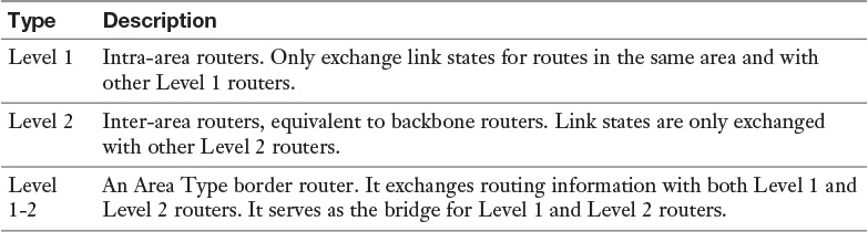
Instead of defining an area type, IS-IS defines a router type. Table 12-11 shows the different IS-IS router types and their definitions.
Instead of LSAs, IS-IS uses Packet Data Units (PDUs). Level 1 routers exchange Level 1 Link State PDUs, and Level 2 routers exchange Level 2 Link State PDUs. Level 1-2 routers exchange both Level 1 and Level 2 Link State PDUs. Like OSPF, all intra-area routers see all Link State PDUs for their level. There are some other PDUs, such as IS-IS Hello PDUs, that are sent by all routers. To connect one area to another area, the connection must be made via two Level 2 routers, Level 1-2 routers, or a combination of the two. Traffic between areas always traverses these connections.
The NSX Edge supports up to three areas and configures different levels in different interfaces. The NSX Edge also supports interfaces joining a Mesh Group. A Mesh Group is a group of IS-IS routers that are fully meshed with each other. An advantage of a Mesh Group is that each IS-IS router in the group only receives a single Link State PDU, thus reducing the overhead of processing PDUs by each router. The Mesh Group could have NSX Edges and physical routers. An IS-IS router only exchanges link status updates with members of the same Mesh Group. Authentication can be configured in the Mesh Group to restrict access to the group. The NSX Edge supports multiple Mesh Groups but an interface can only belong to a single Mesh Group.
To configure IS-IS in the NSX Edge, follow these steps (the logical router does not support IS-IS):
Step 1. From the NSX Home page click NSX Edges.
Step 2. Select the NSX Manager that owns the NSX Edge and double-click the NSX Edge.
Step 3. Go to Manage > Routing and select IS-IS.
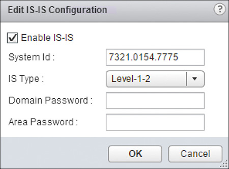
Step 4. In IS-IS Configuration click Edit and wait for the Edit IS-IS Configuration Wizard to pop up.
Step 5. Check the Enable IS-IS box and fill out the following fields:
System ID: Enter the NET for the NSX Edge.
IS Type: Select the default Edge IS-IS router type.
Domain Password (optional): Enter the password for the IS-IS domain.
Area Password (optional): Enter the password for the area(s) the router will be in.
The configuration should look similar to what is shown in Figure 12-14. Click OK.
Step 6. In Areas, click Edit and wait for the Edit IS-IS Areas Wizard to pop up.
Step 7. Enter up to three different areas and click Save. Each area must be between 1 byte to 13 bytes in hexadecimals.
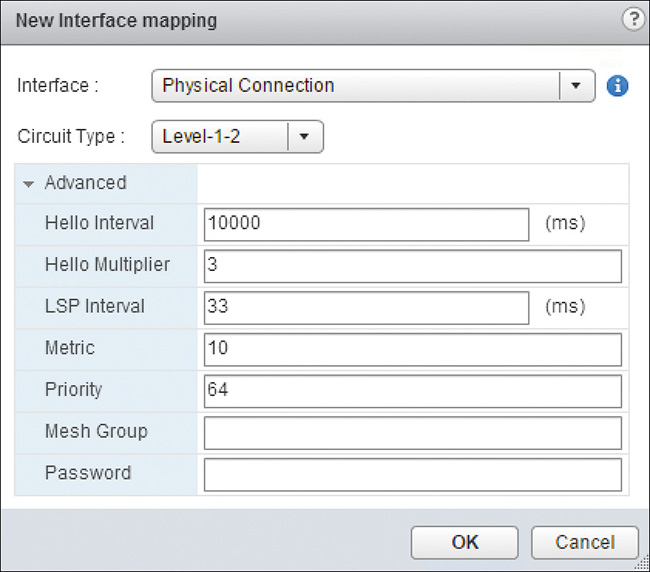
Step 8. In Interface Mapping click the green + icon and wait for the New Interface Mapping Wizard to pop up.
Step 9. Select the Interface you want to run IS-IS and complete the following fields:
Circuit Type: Select Router Level to run over the interface.
In Advanced you can fill out the following fields (or leave them with their default values):
Hello Interval: Enter the frequency to send Hello packets in milliseconds. The default is 10,000 ms.
Hello Multiplier: The number of Hello packets missed before declaring the IS-IS neighbor down. The default is 3 ms.
LSP Interval: The number of milliseconds to wait before sending successive link state packets. The default it 33 ms.
Metric: The cost of the interface. The default is 10.
Priority: The preference for being elected the designated router. The highest priority in the segment wins. The default is 64.
Mesh Group (optional): Enter the Mesh Group number. This number must match for all IS-IS routers in the interface segment.
Password (optional): Enter a password if authentication is required in the Mesh Group.
The configuration should look similar to Figure 12-15. Click Save.
Step 10. Click Publish Changes.
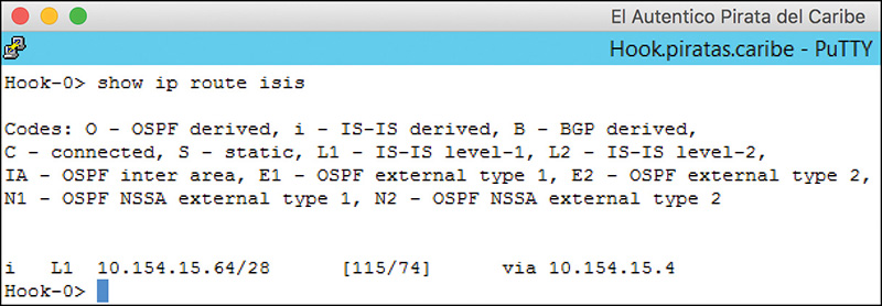
Figure 12-16 shows the output of the command show ip route isis. This command lists all the routes learned via IS-IS.
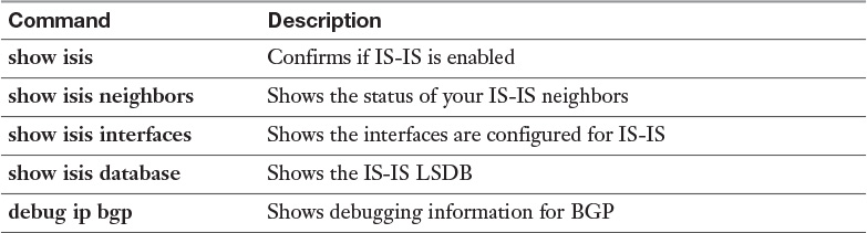
Table 12-12 has a list of commands that can be used to check the status of your IS-IS functionality.
We conclude this chapter by configuring route redistribution. The process is similar in both the logical router and the NSX Edge. The steps required to redistribute routes into a routing process involve identifying the subnets that will be redistributed into the routing process and from where the subnets would be redistributed. The subnets are identified in an IP prefix. An IP prefix includes the IP prefix name, the subnet, and the subnet prefix.
To configure route redistribution, follow these steps:
Step 1. From the NSX Home page click NSX Edges.
Step 2. Select the NSX Manager that owns the Control VM or NSX Edge and double-click the logical router or NSX Edge.
Step 3. Go to Manage > Routing and select Route Redistribution.
Step 4. In Route Redistribution Status, click Change and wait for the Change Redistribution Settings Wizard to pop up.
Step 5. Check the box next to the routing protocol(s) you want to enable redistribution for and click Save.
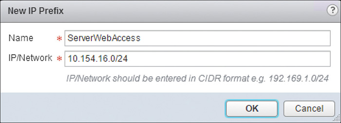
Step 6. In IP Prefix click the green + icon and wait for the New IP Prefix Wizard to pop up.
Step 7. Enter a name for the IP Prefix, enter the subnet and prefix, and click OK. There is a default IP Prefix of ANY to include all subnets.
The configuration should look similar to the one in Figure 12-17.
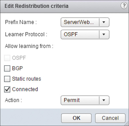
Step 8. In Route Redistribution Table, click the green + icon, wait for the New Redistribution Criteria Wizard to pop up, and fill in the following fields:
Prefix Name: Select the IP Prefix to redistribute.
Learner Protocol: The receiving routing protocol.
Allow Learning From: Select the sources from where the networks in the IP Prefix are coming.
Step 9. In Action, select to Permit or Deny the routes to be injected to the routing protocol.
The configuration should look similar to Figure 12-18. Click OK.
Step 10. Click Publish Changes.
The only way get to get the internal logical router interfaces advertised into OSPF is to redistribute them. When redistributing the connected logical router interfaces into OSPF, they show up in the routing table as OSPF external type 2 routes.
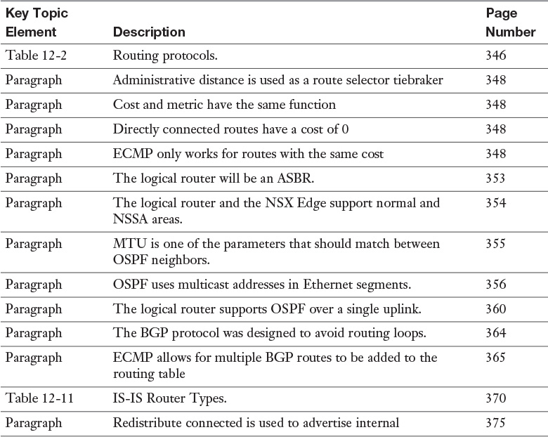
Review the most important topics from inside the chapter, noted with the Key Topic icon in the outer margin of the page. Table 12-13 lists these key topics and the page numbers where each is found.
Download and print a copy of Appendix C, “Memory Tables” (found on the book’s website), or at least the section for this chapter, and complete the tables and lists from memory. Appendix D, “Memory Tables Answer Key,” also on the website, includes the completed tables and lists so you can check your work.
Define the following key terms from this chapter, and check your answers in the Glossary:
Internal Gateway Protocol (IGP)
External Gateway Protocol (EGP)