Objective 6.1—Configure and Manage Logical Load Balancing
This chapter covers all or part of the following VCP6-NV exam blueprint topics:
Objective 6.1—Configure and Manage Logical Load Balancing
Objective 6.3—Configure and Manage DHCP/DNS/NAT
Objective 7.1—Configure and Administer Logical Firewall Services
Objective 9.5—Administer Logging
You have deployed an NSX network using the features covered in this book up to this point. You feel good with yourself. Really GOOD. Now you want to take it up a notch to wow your boss (she is already impressed with you, by the way). You ponder if the best way to go is to use NSX to replace some network functions being done by the other network appliances, such as NAT for the web server. Or would it be best to make the deployments of virtual workloads more dynamic by using the load balancing features of the NSX Edge? Or perhaps do them both plus some firewalling here and there. So many ways you can continue to shine by using NSX. Decisions, decisions...
This chapter covers the additional network and security features that NSX has to offer via the NSX Edge. Similar to Chapter 13, “NSX Edge VPN Services,” these features have been a staple in networking and security for years, and there isn’t much more that could be added in this book regarding those technologies. This chapter provides a quick overview of the features, as needed, to show how the NSX Edge implements those features and how to configure them.
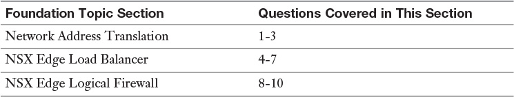
The “Do I Know This Already?” quiz allows you to assess whether you should read this entire chapter or simply jump to the “Exam Preparation Tasks” section for review. If you are in doubt, read the entire chapter. Table 14-1 outlines the major headings in this chapter and the corresponding “Do I Know This Already?” quiz questions. You can find the answers in Appendix A, “Answers to the ‘Do I Know This Already?’ Quizzes.”
1. What is the name of a NAT that changes the source IP of a packet?
a. INAT
b. SNAT
c. DNAT
d. PNAT
2. What is the name of a NAT that changes the destination IP of a packet?
a. INAT
b. SNAT
c. DNAT
d. PNAT
3. Which two NAT rules can be configured in the NSX Edge? (Choose two.)
a. INAT
b. DNAT
c. PNAT
d. SNAT
4. What is an NSX load balancer virtual server?
a. The mapping of the VIP with a server pool and an application profile
b. A virtual machine with an installed operating system
c. The servers that are members of the NSX load balancer server pool
d. The servers that are members of the NSX load balancer application profile
5. What type of load balancing is not supported by the NSX Edge?
a. Load balancing based on the UDP header
b. Load balancing based on the IGMP header
c. Load balancing for applications communicating over HTTP
d. Load balancing for applications communicating over HTTPS
6. What is the load balancing mode the NSX Edge is configured for if an SNAT is done in the user traffic?
a. Layer 4 load balancing mode
b. Transparent mode
c. Layer 7 load balancing mode
d. Proxy mode
7. Which persistence method is not supported for HTTPS?
a. Source IP
b. Destination URI
c. Cookie
d. SSL Session ID
8. Which type of security does the NSX Edge firewall provide? (Choose two.)
a. Layer 2 firewall
b. Layer 3 firewall
c. Layer 4 firewall
d. Layer 7 firewall
9. When processing traffic, where are NSX Edge firewall rules matched against traffic?
a. NSX Edge firewall rules are matched against ingress traffic of the selected Edge vNIC.
b. NSX Edge firewall rules are matched against egress traffic of the selected Edge vNIC.
c. By default, NSX Edge firewall rules are matched against all traffic after any configured NAT rules are applied.
d. By default, NSX Edge firewall rules are matched against all traffic coming in the Edge.
10. If a firewall rule’s source is configured to match a logical switch, how does the NSX Edge match traffic to the firewall rule?
a. The NSX Edge receives the IP address of all vNICs connected to the logical switch from vCenter and uses these IPs to match traffic to the firewall rule.
b. The NSX Edge receives the IP address of all vNICs connected to the logical switch from NSX Manager and uses these IPs to match traffic to the firewall rule.
c. The NSX Edge receives the IP address of all vNICs connected to the logical switch from the ESXi hosts and uses these IPs to match traffic to the firewall rule.
d. The NSX Edge receives the IP address of all vNICs connected to the logical switch from the NSX Controllers and uses these IPs to match traffic to the firewall rule.
A Network Address Translation (NAT) device (typically a router) changes either the source or destination IP of an IP packet. If the NAT router changes the source IP, then the NAT is called a Source NAT (SNAT). If the NAT router changes the destination IP, then the NAT is called a Destination NAT (DNAT). The underlying logic in SNAT is rather simple: If an ingress packet arrives in the router matching a particular source IP, the source IP is changed for a predetermined one and then the packet is sent on its way. The same logic applies if doing DNAT. The NSX Edge supports SNAT and DNAT.
The configurations for applying NAT are done via NAT rules. For NAT rules to be effective, an interface must be identified, and the direction of the packet flow is based on this interface. Packets arriving at this interface are considered ingress packets, and packets going out of this interface are considered egress packets. If an SNAT rule is applied to an interface, the source IP address of the ingress packet is changed. If a DNAT rule is applied to an interface, the destination IP of the egress packet is changed. The NAT router keeps a NAT table of all translated IPs so return traffic in the flow can have the NAT reversed. The return traffic must come through the interface that has the NAT rule that was applied to the flow.

NAT is designed to be transparent to the end user. An SNAT rule is usually applied when the source subnet in the packet should remain unreachable by the destination. A typical application of an SNAT rule is to allow a virtual workload to initiate a flow with an entity outside its subnet. A DNAT rule is usually applied when the actual destination of a packet should remain unreachable by the source. A DNAT rule is required for traffic that originates from entities outside the subnet of the virtual workload.
To configure a DNAT rule in the NSX Edge, follow these steps:
Step 1. From the NSX Edges view, double-click the NSX Edge that will be configured with NAT.
Step 2. Go to Manage > NAT.
Step 3. Click the green + icon, select Add DNAT Rule, and wait for the Add DNAT Rule Wizard to open.
Step 4. In the Applied On field, select the interface to apply the NAT rule.
Step 5. In Original IP/Range, enter the destination IP or destination IP range to translate.
This is matched against the destination IP in the packets.
This field may include one of the following formats:
IP: Example 10.10.62.3
IP Range: Example 10.10.62.3-10.10.62.31
IP Subnet and CIDR: Example 10.10.62.0/24
The keyword Any to include all IPs
Step 6. (Optional) In Protocol, select the protocol that triggers the enforcement of this NAT rule.
(Optional) If you selected a protocol in step 5, you may enter the port number or range in Original Port/Range.
Step 7. In Translated IP/Range, enter the IP or IP range to use for translation.
This field may include one of the following formats:
IP: Example 10.10.62.3
IP Range: Example 10.10.62.3-10.10.62.31
IP Subnet and CIDR: Example 10.10.62.0/24
Step 8. (Optional) In Translated Port/Range enter the ports to translate to.
Step 9. Enter an optional description.
Step 10. Check the Enabled box to enable the rule.
Step 11. Check the Enable Logging box to enable logging for this rule.
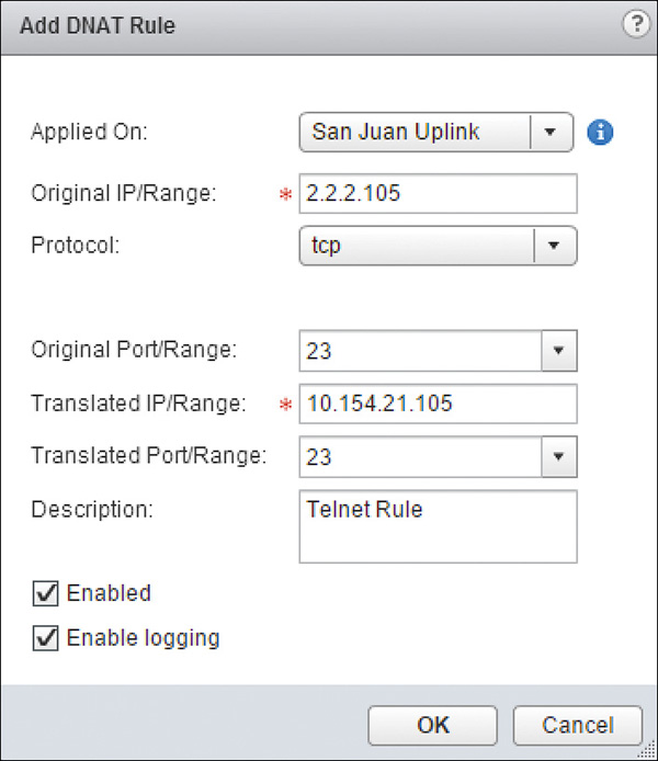
Figure 14-1 shows a sample configuration for a DNAT rule. Click OK.
Step 12. Click Publish.
To configure an SNAT rule in the NSX Edge follow these steps:
Step 1. Go to Manage > NAT.
Step 2. Click the green + icon, select Add SNAT Rule, and wait for the Add SNAT Rule Wizard to open.
Step 3. In the Applied On field, select the interface to apply the NAT rule.
Step 4. In Original Source IP/Range, enter the source IP or source IP range to translate.
This is matched against the source IP in the packets.
This field may include one of the following formats:
IP: Example 10.10.62.3
IP Range: Example 10.10.62.3-10.10.62.31
IP Subnet and CIDR: Example 10.10.62.0/24
The keyword Any to include all IPs
Step 5. In Translated Source IP/Range, enter the IP or IP range to use for translation.
This field may include one of the following formats:
IP: Example 10.10.62.3
IP Range: Example 10.10.62.3-10.10.62.31
IP Subnet and CIDR: Example 10.10.62.0/24
If the number of IPs in step 4 is larger than the number of available IPs in step 5, then NAT overload would take place. In NAT overload (also referred to as One to Many or Many to Many NAT), in addition to doing NAT on the Source IP, NAT would be done to the Source Port number. This allows multiple source IP addresses to use the same NAT source IP.
Step 6. Enter an optional description.
Step 7. Check the Enabled box to enable the rule.
Step 8. Check the Enable Logging box to enable logging for this rule.
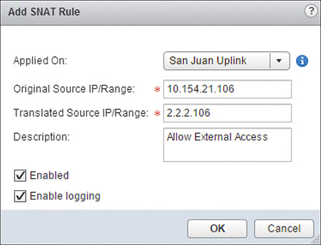
Figure 14-2 shows a sample configuration for an SNAT rule. Click OK.
Step 9. Click Publish.
In SNAT, if the number of Original Source IPs is more than the number of Translated Source IPs, the NSX Edge does Port NAT. Port NAT, sometimes referred to as pNAT or NAT Overload, changes the source port number while allowing multiple sources to use the same translated source IP.
Load balancers started their lives as super-duper NAT entities. They provided a simple load balancing solution for applications. If you had a web server farm hosting the same page, how else do you balance the influx of page requests so that one of the web servers wouldn’t be overloaded while you had other web servers with plenty of available capacity to accept new requests? Early load balancers were simple NAT servers or routers doing One to Many DNAT. That is, the destination IP in the packet was changed by the load balancer to one of the translated IPs, which were the IPs of the web servers. New connections were then round robin among the load balanced servers.
Fast-forward to the present day. Load balancers have come a long way from those humble beginnings. They continue to do some sort of DNAT but can be very granular in terms of how traffic flows are apportioned among the balanced workloads and have the capability to look into Layer 7 of the packet to make even more efficient load balancing decisions. In addition, load balancers can also terminate connections on behalf of the workloads. This feature is often used for SSL, where the load balancer offloads the SSL termination from the web servers and establishes a new connection to the web server. The new connection may be an SSL connection or a non-SSL connection.
At the basic level, load balancers work by having a virtual IP (VIP) that is the destination IP of all traffic going to the particular service, such as our web page example. The VIP is mapped in the load balancer to an application that represents the service, called the application profile. The application profile is load balanced to a list of servers running the workload, called the server pool. The IPs in the server pool act as the equivalent of the translated destination IPs in a DNAT rule. Traffic that matches the criteria included in the application profile triggers ingress traffic to be load balanced.
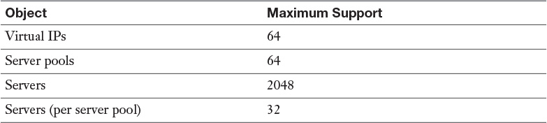
Once a VIP is mapped to an application profile and server pool, it is called a virtual server. The NSX Edge can have virtual servers that trigger load balancing based on Layer 4 information, TCP and UDP, Layer 7 information, and HTTP and HTTPS. Table 14-2 shows the maximum number of VIPs, server pools, and servers that the Edge supports.
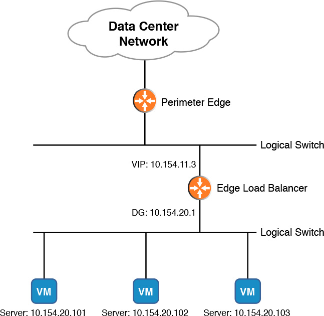
Figure 14-3 shows an example of an NSX Edge load balancer. The Edge has a VIP of 10.10.50.4, a server pool that includes IPs 10.10.11.101, 10.10.11.102, and 10.10.11.103, and an application profile that matches destination TCP ports 80 or 8080. In Figure 14-3, any user that wants to reach a web page on ports 80 or 8080 at 10.10.50.4 is redirected to one of the three servers in the server pool. The redirection happens by doing a DNAT on the user packets. The source IP of the packets is not altered.
The load balancer configuration shown in Figure 14-3 is called In-Line or Transparent Mode. This is the traditional load balancer setup, where one of the load balancer’s interfaces is exposed to the “outside” with the VIP, and a second interface is directly connected to the segment where the server pool members reside. By being directly connected to the same segment as the servers in the server pool, they require that the Edge load balancer be their default gateway. Yes, you read that correctly: When deploying the load balancer in Transparent Mode, the Edge must have an interface directly connected to the segment where the members in the server pool are located, and the Edge must be the default gateway for the servers.
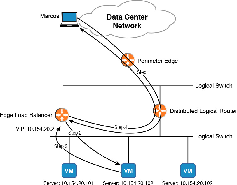
An alternate deployment to Transparent Mode is One-Arm or Proxy Mode. In this configuration, the NSX Edge load balancer uses a single interface, and the logical router may be used as the default gateway for the members in the server pool, as shown in Figure 14-4. The VIP is in the same subnet as the server pool servers’ subnet.
In Proxy Mode a user sends application requests to the VIP, and the Edge does DNAT to redirect the traffic to one of the members in the server pool. However, since the members in the server pool have a default gateway that is not the Edge, the Edge must also do an SNAT on the user traffic to force return traffic from the members in the server pool to go through the Edge. The translated SNAT IP the NSX Edge uses is the VIP. Figure 14-5 shows our friend Marcos from the San Juan office opening a web page being load balanced by the Edge in Proxy Mode in the Santo Domingo Data Center.
1. Marcos opens a browser to connect to the website http://blog.senasosa.com. The DNS Server resolves the page to the VIP of 10.10.11.2.
2. The load balancer receives the browser traffic, matches the request to an application profile, and forwards the traffic to the next available server in the server pool.
a. The Edge does SNAT on Marcos’s IP, replacing it for the VIP.
b. The Edge does DNAT on the VIP, replacing it for the IP of the selected web server.
c. The decision on which server to select depends on the load balancing algorithm configured in the server pool. The NSX Edge can use six different load balancing algorithms:
Round Robin: New flows are sent to the servers in the server pool in a sequential order.
Least Connections: The server with the least number of connections is selected.
IP Hash: A hash is computed on the user’s IP, the source IP of the packet, and used to select a server.
Uniform Resource Identifier (URI): A hash is computed on the left part of the URI (the left of the question mark), divided by the total weight of the running members in the server pool, and used to select a server. URI load balancing hash is only supported for Layer 7 load balancing.
Uniform Resource Locator (URL): A hash is computed on the left part of the URL, divided by the total weight of the running members in the server pool and used to select a server. URL load balancing hash is only supported for Layer 7 load balancing.
HTTP Header: A hash is computed based on the HTTP header. HTTP header load balancing is only supported in Layer 7 load balancing.
3. The selected web server receives the traffic and responds.
a. The web server sees the traffic coming from the VIP.
b. The load balancer can use the x-forwarded-for HTTP header to let the web server know the traffic is not being sourced from the VIP.
4. The Edge receives the return traffic, undoes the SNAT and DNAT, and forwards the traffic to Marcos.
If the NSX Edge is configured with firewall rules and a Layer 4 load balancer, the Layer 4 VIP is processed before the firewall rules, thus no need to add an Allow Firewall rule.
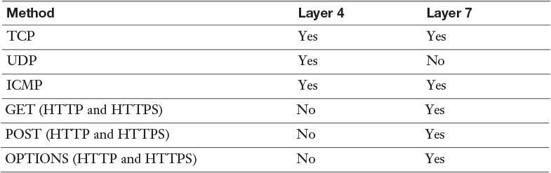
So this covers the basics of what an NSX Edge load balancer does. Now let’s talk about other features the NSX Edge load balancer supports. There is this thing called Service Monitor, also referred to as Health Check, where the load balancer monitors the up state of the members in the server pool. If a particular member is determined to be unavailable, the Edge removes the member from the server pool; actually, the server is not removed from the pool per se, but rather marked as down, so it won’t be selected for any new traffic flows. Table 14-3 shows the Service Monitor methods the NSX Edge supports for Layer 4 and Layer 7.
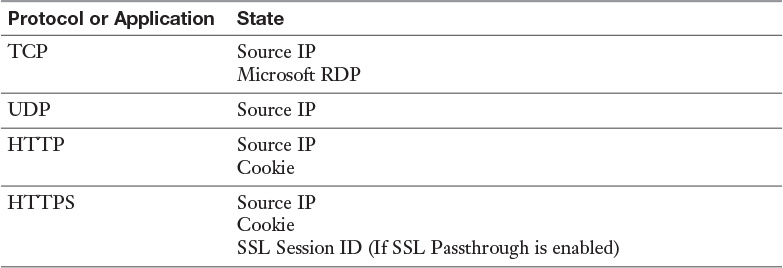
If the NSX Edge is configured with Edge HA, the state of the load balancing table, or persistence, is synchronized between the Active Edge and the Standby Edge if the load balancing is being done at Layer 7. Whenever the Active Edge goes down and the Standby Edge becomes the Active Edge, it retains the user session persistence by sending the user traffic to the same server(s). Table 14-4 shows the persistence states that are synced between the Active and Standby Edges.
The NSX Edge supports throttling to the virtual server and members in the server pool. Table 14-5 shows the methods the Edge can use to throttle access.
One neat feature of NSX is the capability to use an NSX-registered third party’s load balancer. When configured, NSX Manager pushes the load balancer configuration to the third party’s load balancer rather than the NSX Edge.
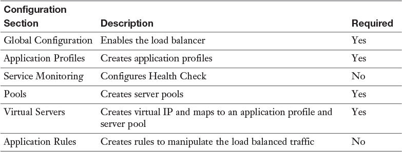
Now we are up to configuring the Edge to be a load balancer. Table 14-6 shows all configuration parts that can be done in the Edge and points out those that are a requirement. In this section we cover the four sections that must be configured to get a working load balancer.
To create an application profile, follow these steps:
Step 1. From the NSX Edges view, double-click the NSX Edge that will be configured as a Load Balancer.
Step 2. Go to Manage > Load Balancer and select Application Profile.
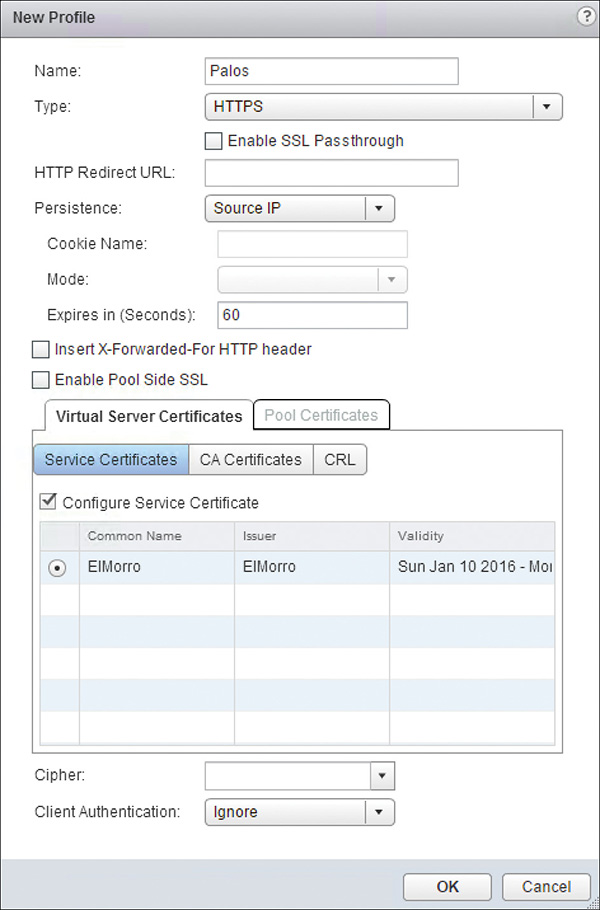
Step 3. Click the green + icon and wait for the New Profile Wizard to open.
Step 4. Give the profile a name.
Step 5. Select one of the load balancing methods:
a. TCP: Load balancing is done at Layer 4. A TCP number is required.
b. UDP: Load balancing is done at Layer 4. A UDP number is required.
c. HTTP: Load balancing is done at Layer 7.
d. HTTPS: Load balancing is done at Layer 7.
i. If the servers in the server pool are terminating SSL, check the box Enable SSL Pass-through.
ii. If Enable SSL Pass-through is not checked, the Edge does SSL termination and a digital certificate is required.
Step 6. (Optional) If doing HTTP or HTTPS load balancing, enter the URL to redirect web traffic.
Step 7. (Optional) Select the persistence to use. If cookie is chosen, enter the cookie name and the mode.
Step 8. (Optional) check the box for Insert-X-Forwarded-For HTTP header.
Step 9. (Optional) Enable Pool Side SSL.
a. Makes the Edge start an SSL (HTTPS) connection to the selected server in the server pool. If not checked, the Edge starts an HTTP connection to the selected server in the server pool.
b. This option is only available if the load balancer is doing the SSL termination (see step 5d, ii).
Step 10. In the Virtual Server Certificates and the Server Pool, select the Certificate, CA, and Certificate Revocation List, if any.
a. Virtual Server Certificates are available only if the load balancer is doing the SSL termination (see step 5d, ii).
b. If Enable Server Pool is checked, a digital certificate for the server pool must be selected in Pool Certificates.
Step 11. (Optional) Select the cipher to use for the SSL handshake.
a. If none is selected, the default cipher is used.
b. This option is only available if the load balancer is doing the SSL termination.
Step 12. (Optional) Choose if the user must authenticate.
a. If authentication is required, the user must have a digital certificate.
b. This option is only available if the load balancer is doing the SSL termination.
Step 13. The configuration should look similar to Figure 14-6. Click OK.
Step 14. Repeat steps 3 through 13 to add more application profiles.
To create a server pool, perform the following steps:
Step 15. Select Pools.
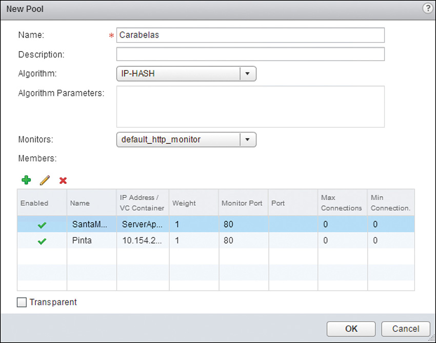
Step 16. Click the green + icon and wait for the New Pool Wizard to open.
Step 17. Assign the pool a name. You can also add a description.
Step 18. Select the load-sharing algorithm. The options are listed in Table 14-4.
Step 19. In Monitors, select the type of Health Check to do against the members in the pool. The Health Checks are created and configured in the Service Monitoring section.
Step 20. Click the green + icon to add a server to the server pool.
Step 21. In the New Member window that opens, enter the following information:
a. Give the server a name.
b. Enter the IP address of the server or select a vCenter object, such as a cluster or the actual VM name.
i. If selecting a vCenter object that contains more than one virtual machine, all the virtual machines become members of the server pool.
c. (Optional) Enter the TCP or UDP port to forward user traffic to the server.
d. (Optional) Enter the TCP or UDP port the Edge uses to monitor the server.
e. Enter a weight. The weight is used to calculate the likeliness a server will be chosen if the load balancing algorithm is Round Robin or URI. The higher the weight of the server relative to the other servers in the pool, the more frequently the server will be selected.
f. (Optional) Enter the maximum and minimum number of connections the server can have.
g. Check the Enabled box to have this server active in the pool.
h. Click OK.
Step 22. Repeat step 20 and 21 to add more members to the pool.
Step 23. (Optional) Check the box for Transparent. If the box is checked, the Edge will be in Transparent Mode and only do DNAT on user traffic. If the box is not checked, the NSX Edge will be in Proxy Mode and do DNAT and SNAT on user traffic.
Step 24. The configuration should look similar to Figure 14-7. Click OK.
Step 25. Repeat steps 16 through 24 to add more server pools.
To configure the virtual server, follow these steps:
Step 26. Select Virtual Server.
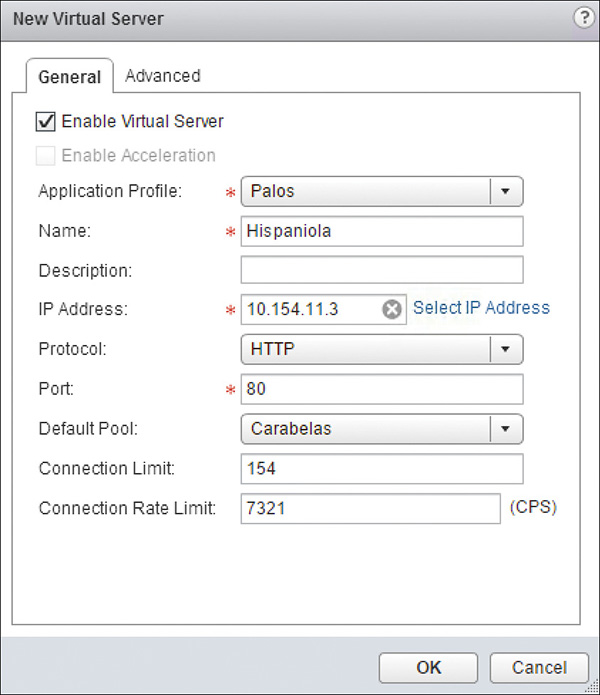
Step 27. Click the green + icon and wait for the New Virtual Server Wizard to open.
Step 28. In the General tab, check the Enabled box.
Step 29. (Optional) Enable Acceleration. This option is available if acceleration is enabled in the Global Configuration. When this box is checked, load balancing is done using the Layer 4 information of the packet.
Step 30. Select the Application Profile to map.
Step 31. Give the virtual server a name and description.
Step 32. In IP Address, enter the VIP or select an IP from one of the Edge’s interfaces.
Step 33. Select the Protocol and enter the TCP Port the virtual server is listening to. The Protocol options are TCP, UDP, HTTP, and HTTPS.
Step 34. Select the Server Pool to map. This field actually reads Default Pool.
Step 35. (Optional) Enter the maximum number of concurrent connections in Connection Limit.
Step 36. (Optional) Enter the maximum number of new connections in Connection Rate Limit.
Step 37. (Optional) If any application rules were created, add them in the Advanced tab.
Step 38. The configuration should look similar to Figure 14-8. Click OK.
Step 39. Repeat Steps 27 through 38 to add more virtual servers.
Finally, we need to enable the load balancer feature in the NSX Edge. To enable load balancing, as well as a few other features, follow these steps:
Step 40. Select Global Configuration.
Step 41. Click Edit.
Step 42. In the opening window, check the box for Enable Load-Balancer.
Step 43. Check the box for Enable Acceleration to only use Layer 4 information of the packet for load balancing.
Step 44. Check the box to enable logging, and choose the log level.
Step 45. Check the box for Enable Service Insertion to redirect traffic to another vendor’s load balancer. You need to select the load balancer in the Service Definition, the Service Configuration, and the Service Profile, and choose the Runtime NICs.
Step 46. Click OK.
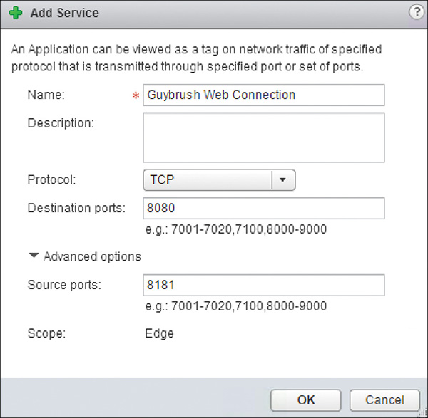
An NSX Edge Service is a collection of Layer 3 (protocols) and Layer 4 (ports). It is a handy way of grouping related protocols, such as ICMP and IPv6, and ports, such as TCP source and destination ports, which can then be referenced in firewall rules. Examples of supported Layer 3 protocols are ARP, IPv4, IPv6, and IPX (yes, there is still some IPX out in the wild). Examples of Layer 4 protocols are TCP, UDP, and ICMP.
To create a new NSX Edge Service, follow these steps:
Step 1. From the NSX Edges view, double-click the NSX Edge where the Service will be created.
Step 2. Go to Manage > Grouping Objects and select Service.
Step 3. Click the green + icon and wait for the Add Service Wizard to open.
Step 4. Enter a unique name for the service.
Step 5. Enter an optional description for the service.
Step 6. In Protocol, use the drop-down to select the protocol desired.
Step 7. If selecting a protocol such as TCP or UDP, enter the Destination port. You can also enter a Source port.
Step 8. Figure 14-9 shows a sample configuration for TCP ports. Click OK.
The NSX Edge can be a DHCP server for virtual machines or forward DHCP requests to a DHCP server via DHCP Relay. The NSX Edge listens to DHCP discovery on internal interfaces. To configure the NSX Edge as a DHCP server, follow these steps:
Step 1. From the NSX Edges view, double-click the NSX Edge where the service will be created.
Step 2. Go to Manage > DHCP and select Pools.
Step 3. Click the green + icon and wait for the Add DHCP Pool window to open.
Step 4. Enter the first and last IPs in the IP pool to use for DHCP.
Step 5. Enter the domain name.
Step 6. Enter a Primary and a Secondary DNS server. If you check the box for Auto Configure DNS, the default gateway IP is used as the DNS server. You should configure DNS servers in the NSX Edge. Adding DNS servers in the NSX Edge is covered step-by-step after this.
Step 7. Enter the default gateway IP. If left blank and the IPs in the pool are part of a subnet of an internal interface, the Edge uses the interface’s IP as the default gateway.
Step 8. Enter the lease time. You have an option to have no expiration by checking the box for Lease Never Expires.
Step 9. Click OK.
Step 10. Click Enable.
Step 11. Choose whether to log, and select the logging level.
Step 12. Click Publish Changes.
To configure DHCP Relay, follow these steps:
Step 1. From the NSX Edges view, double-click the NSX Edge where the Service will be created.
Step 2. Go to Manage > DHCP and select Relay.
Step 3. Click Edit and wait for the Modify DHCP Relay Global Configuration window to open.
Step 4. Enter the IP sets, IP addresses, or domain names of the DHCP servers.
Step 5. Click OK.
Step 6. Under DHCP Relay Agents, click the green + icon and wait for the Add DHCP Relay Agent window to open.
Step 7. Select the internal vNIC to listen for DHCP discovery and select the Gateway IP. If the vNIC has multiple IPs, you may select any of the IPs to be the source of the DHCP Relay packet sent to the DHCP server.
Step 8. Click OK.
Step 9. Repeat steps 7 and 8 to add more internal interfaces.
Step 10. Click Publish Changes.
To add DNS servers to the NSX Edge, follow these steps:
Step 1. Go to Manage > Settings and select Configuration.
Step 2. In DNS Configuration click Change.
Step 3. Check the box for Enable DNS Service.
Step 4. Enter the IP address of up to two DNS servers.
Step 5. Enter the cache size.
Step 6. Choose whether to log, and select the logging level.
Step 7. Click OK.
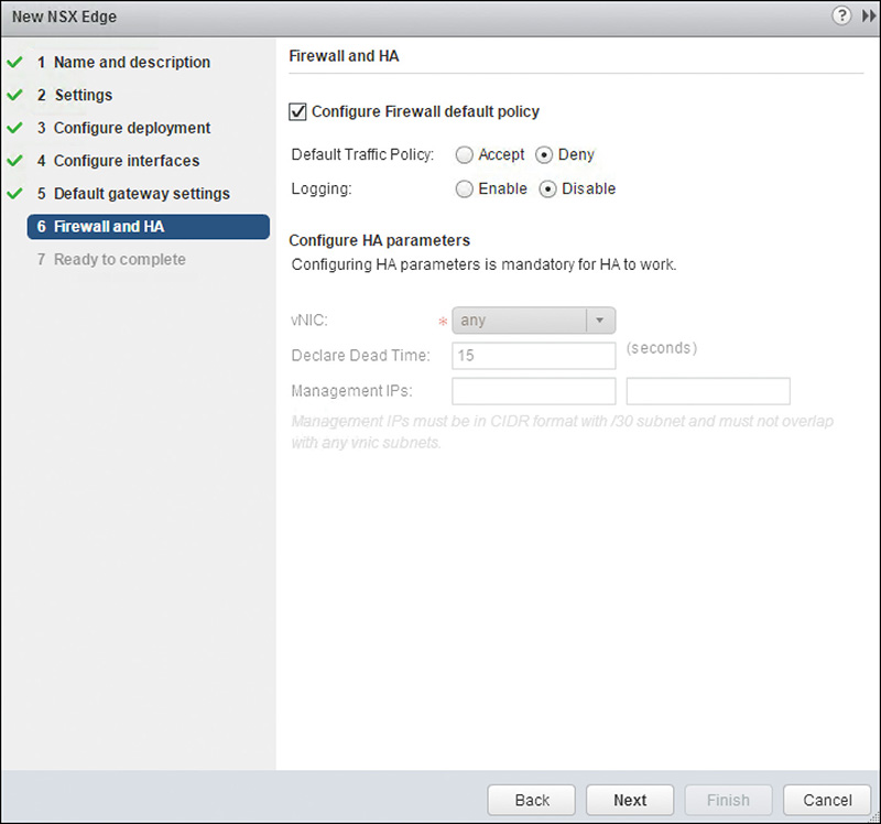
To wrap up the chapter, let’s go over the NSX Edge logical firewall, or simply NSX Edge firewall. The NSX Edge firewall is one of two logical firewalls in NSX. The other is the distributed logical firewall or distributed firewall. The NSX Edge can be configured as a Layer 3 and Layer 4 stateful firewall, primarily to provide security for traffic going between the virtual and physical environments, also referred to as North-South traffic. Firewall rules are processed by the Edge from top to bottom, with a default rule at the bottom. The default rule’s default action is to block all traffic; however, the default action can be changed during the deployment of the NSX Edge. Figure 14-10 shows the step in the New Edge Wizard where you can change the default action of the default rule to accept all traffic.
The Control VM’s firewall is used only for traffic sourced or destined to the Control VM’s HA IP, Protocol IP, or Uplink interfaces. The Control VM’s firewall rules won’t be enforced in internal interfaces.
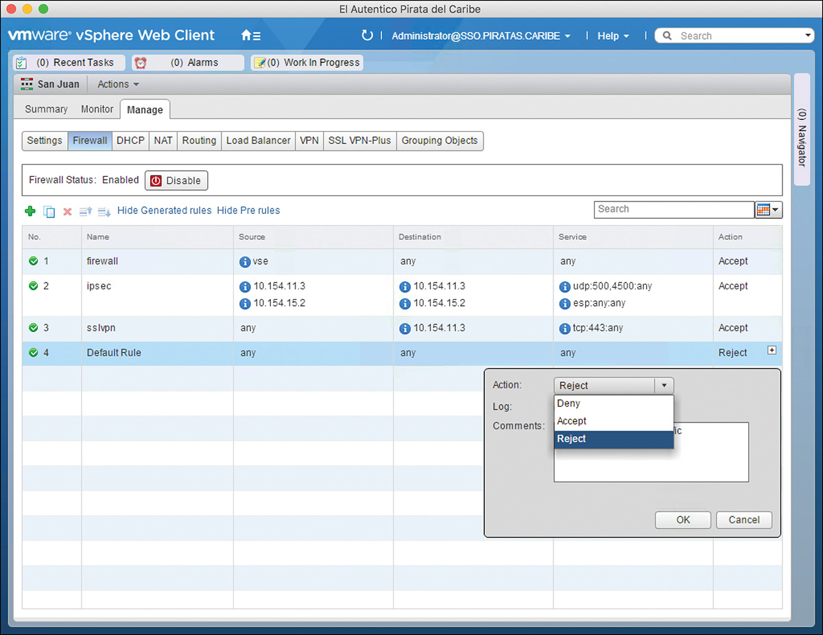
If you didn’t change the default rule’s action during the deployment of the NSX Edge, you can change it by going to Management > Firewall and clicking the white + icon in the Action column of the default rule, as shown in Figure 14-11. In addition to Accept and Deny, you can also choose to Reject the connection. This sends an ICMP destination-unreachable back to the sender of the packet.
Something that I find neat about the Edge firewall is that the Edge can be configured to automatically add firewall rules needed for control traffic functions. For example, if you configure an IPsec VPN, the Edge creates an Allow Firewall rule to permit IPSec traffic between itself and the IPsec VPN peer, as shown in Figure 14-12.
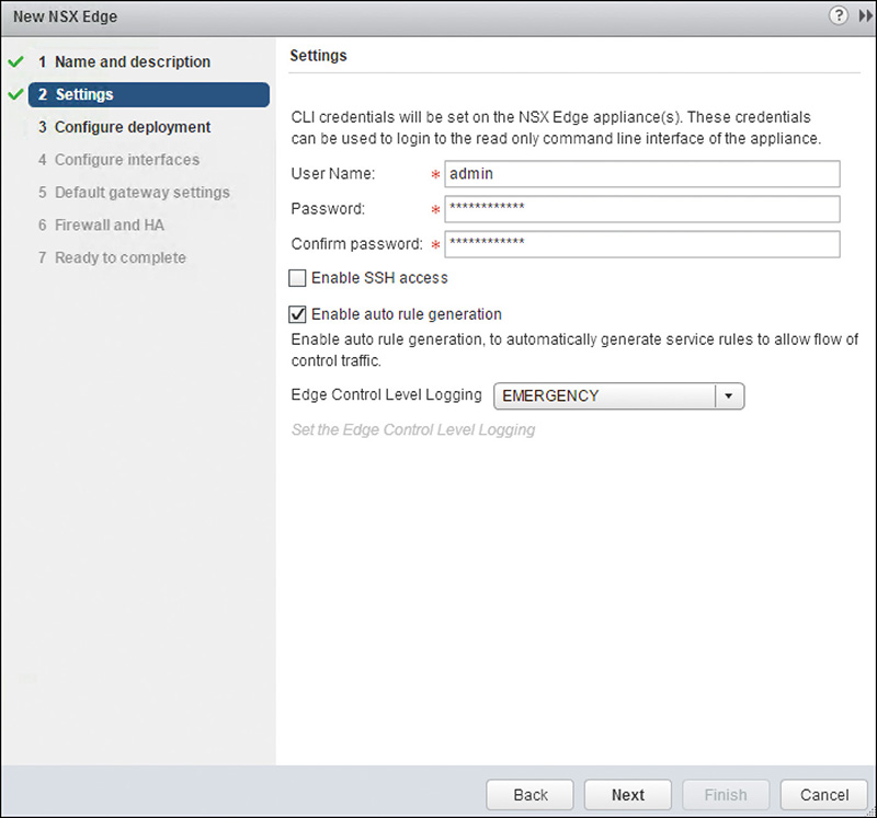
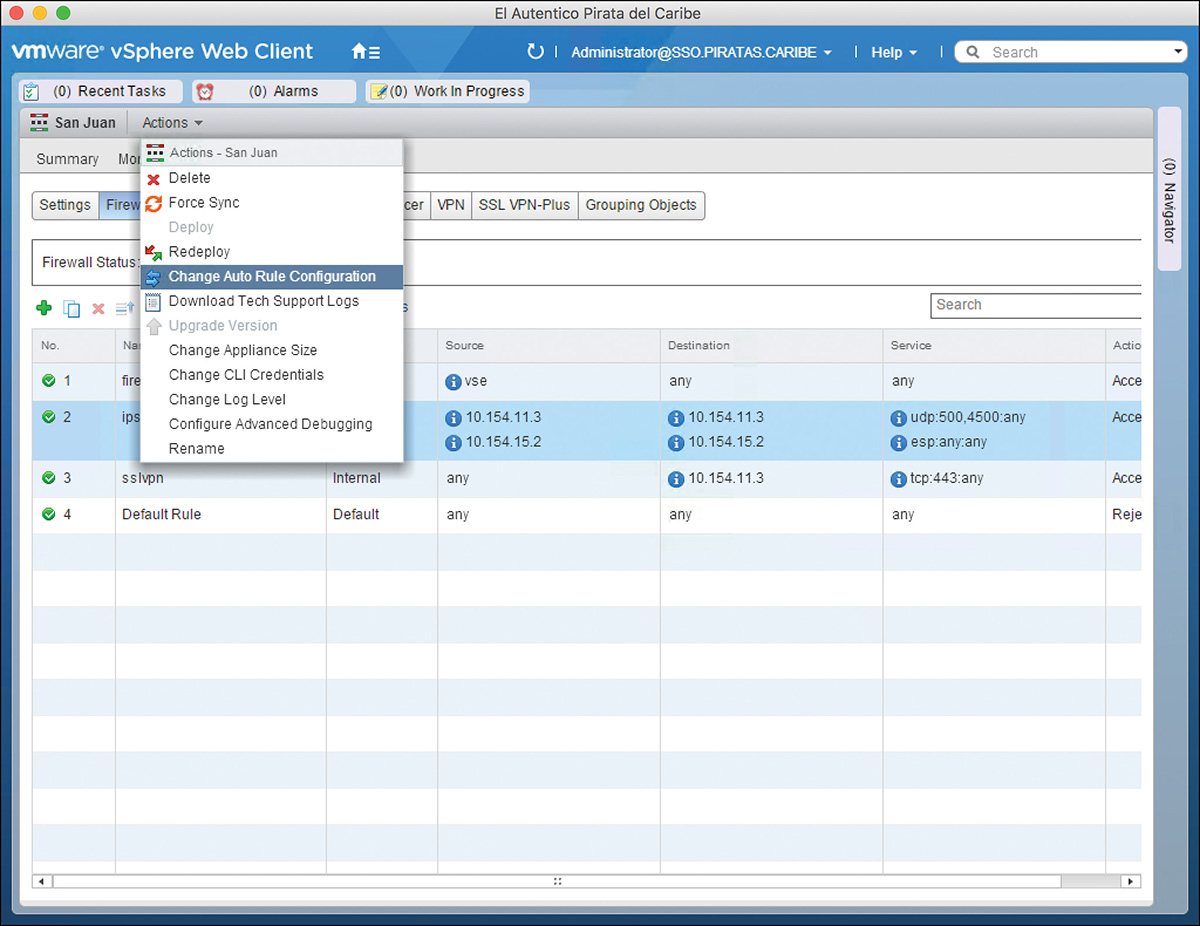
You can configure the Edge to autogenerate firewall rules during the NSX Edge deployment, as shown in Figure 14-13, or by selecting the Edge’s Actions > Change Auto Rule Configuration, as shown in Figure 14-14.
Let me point out one more thing about the Edge firewall rules. The firewall rules are not applied to the Edge interfaces. The rules are applied to all traffic coming into the Edge, and by default they are applied before any NAT is done. You can change this setting on a per-rule basis.
To configure a firewall rule in the NSX Edge follow these steps:
Step 1. From the NSX Edges view, double-click the NSX Edge that will be configured as a firewall.
Step 2. Go to Manage > Firewall.
Step 3. Click the green + icon. A new empty firewall rule is added.
Step 4. In the Name column, click the white + icon and enter the name of the firewall rule.
Step 5. In the Source and Destination columns, click the white + icon to change the source and destination from the default of any. This allows the Edge to use vCenter and NSX Manager objects information to formulate the firewall rule. You can click the red ip icon to enter IP addresses.
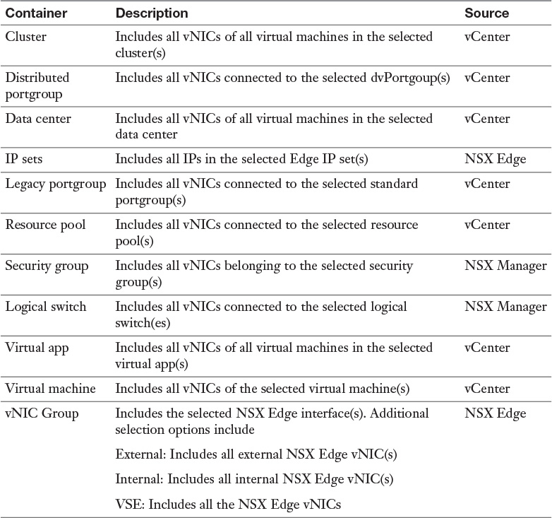
Table 14-7 shows the container objects that can be referenced in the firewall rule.
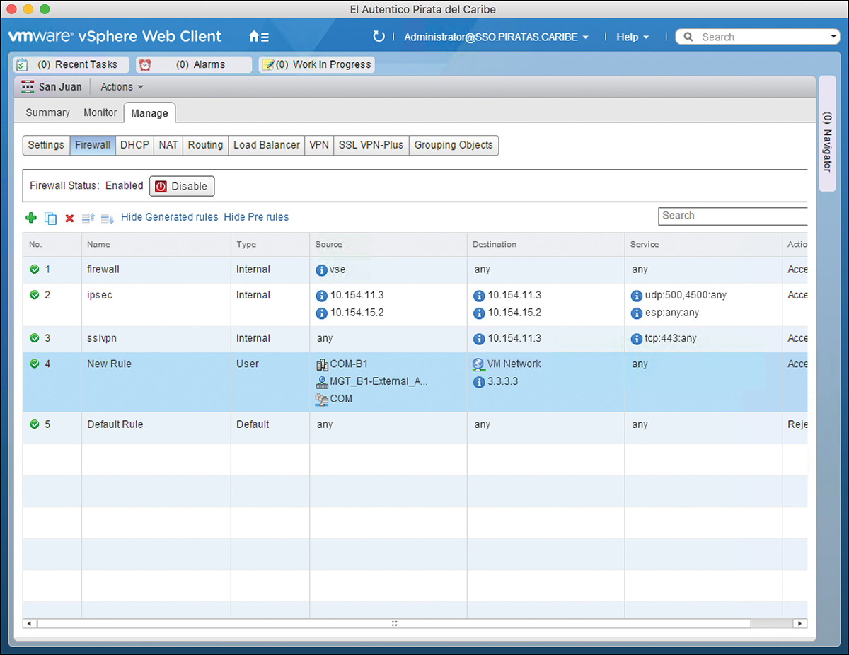
A single firewall rule source and destination can have multiple entries. For example, a firewall rule’s source may have a cluster, a vDS portgroup, and a virtual machine, while the same rule’s destination may have a network and an IP, as shown in Figure 14-15. If traffic matches any of the entries in the source and any of the entries in the destination fields of the rule, then the rule will be processed (if it also matches any of the Service entries, as detailed in step 6).
The Edge processes packets based on the information in the Layer 3 header; thus, it needs the actual IP of every VM that is a member of the objects listed in the source and destination columns for the firewall rule. To get the VM’s IPs, NSX Manager queries vCenter for the IPs, which then provides them to the Edge. The IPs are obtained by VMware Tools, DHCP snooping, or ARP snooping.
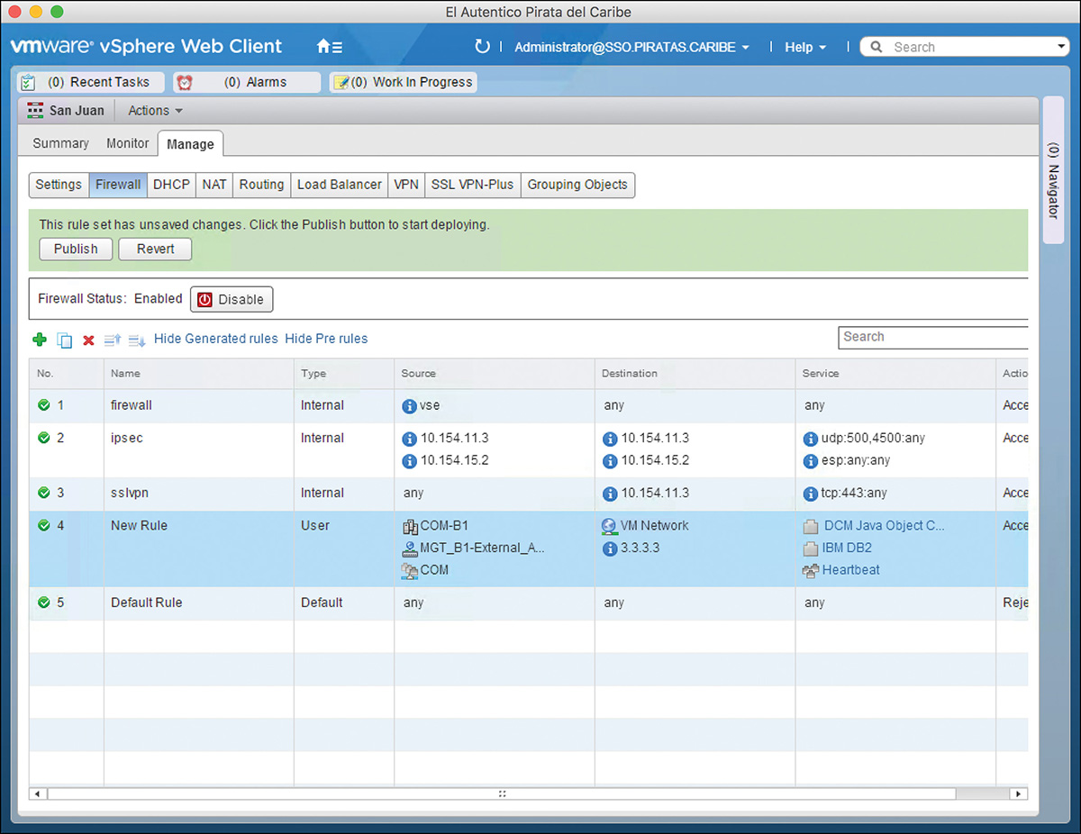
Step 6. In the Service column, click the white + icon to change the default of any. As in the Source and Destination columns, you can enter multiple Services in the same rule.
Step 7. In the Action column, click the white + icon.
a. A pane opens.
b. Set the Action to Allow, Block, or Reject.
c. Choose to Log or Do Not Log when traffic matches the rule.
d. Enter a comment to describe the rule’s function.
e. Click the Advance Options to make visible additional configuration options.
i. In Match On, you can select to match traffic on the translated NAT IP. This causes NAT to be done first before the firewall rule is processed. The default behavior is to match the firewall rule before doing NAT.
ii. In Enable Rule Direction, you can set to match rules on ingress traffic or egress traffic. VMware does not recommend setting this option (I know, I know, why have the option then? Good question  ).
).
f. The configuration should look similar to Figure 14-16. Click OK.
Step 8. Click Publish.
As of NSX 6.2, NSX Edge firewall rules can also be created from the Firewall page in Network and Security. NSX Edge firewall rules created in the Firewall page of Network and Security are enforced before any firewall rules created in the NSX Edge Firewall page and have a firewall rule type of Pre-Rules. We cover this page in Chapter 15, “Distributed Logical Firewall.”
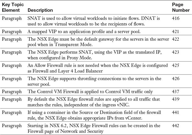
Review the most important topics from inside the chapter, noted with the Key Topic icon in the outer margin of the page. Table 14-8 lists these key topics and the page numbers where each is found.
Download and print a copy of Appendix C, “Memory Tables,” (found on the book’s website), or at least the section for this chapter, and complete the tables and lists from memory. Appendix D, “Memory Tables Answer Key,” also on the website, includes the completed tables and lists so you can check your work.
Define the following key terms from this chapter, and check your answers in the glossary: