Chapter 14
Light and Optics
GOALS
By the end of this chapter, you will be able to:
• Define light and describe the electromagnetic spectrum
• Describe how light acts at a boundary between two media
• Calculate the angle of refraction for light passing between two media
• Explain how optical systems produce real and virtual images
• Calculate the positions of real and virtual images produced by optical systems using the thin lens equation
Lesson 14.1
Light
Light is a transverse wave just like a mechanical wave. However, instead of position oscillating, light is composed of oscillating electric and magnetic fields. The electric and magnetic fields are both perpendicular to each other and to the propagation of the light (which is why it is a transverse wave). This is illustrated in the following figure.


Figure 14.1: Light as a Transverse Wave
As mentioned in Chapter 10, light is the only wave that does not require a medium to travel in. Prior to 1887, it was thought that light, as with all waves, must move in a medium. This medium was known as the aether. In the summer of 1887, two American physicists, Albert Michelson and Edward Morley, performed an experiment to measure the direction and speed of the aether on Earth. While conducting their experiment, now known as the Michelson-Morley experiment, they showed that the aether doesn’t actually exist. This discovery was one of the most important discoveries of the late 19th century, and it is what led Einstein to develop his special Theory of Relativity, as mentioned before.
In a vacuum, the speed of light is defined as
Equation 14.1
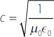
which is
c = 3.0 × 10⁸ m/s
Like all waves, the speed of light changes as it passes between media, but the speed of light is fastest in a vacuum. In any transparent medium (a medium that light can pass through), the speed of light will be
Equation 14.2
V = 
where n is known as the index of refraction. The index of refraction is always greater than 1 for a transparent medium, since light has to move slower in a medium than it does in a vacuum.
It is an absolute law in the universe that nothing can travel faster than the speed of light in a vacuum. This does not mean that nothing can travel faster than the speed of light in a transparent medium. In Chapter 10, we talked about what happens when an object goes supersonic. It produces a sonic boom, an incredibly loud sound. It turns out that if a charged particle travels faster than the speed of light in a transparent medium, it emits a burst of radiation very similar to a sonic boom known as Cherenkov radiation, named after the Russian physicist Pavel Cherenkov, who shared the 1958 Nobel Prize in Physics for the discovery. This is why radioactive materials glow—they are emitting charged particles that are moving faster than the speed of light in the medium the charged particles are in, and these charges are emitting Cherenkov radiation as a result.
Light is classified based on the energy that it carries, which is given by the following equation:
Equation 14.3
E = hf
where h is known as Planck’s constant, after the German physicist Max Planck, and f is just the frequency of the light. Planck’s constant is
h = 6.626 × 10⁻³⁴ J·s
This classification of light is known as the electromagnetic spectrum. Since energy is dependent upon frequency, and you know that the frequency of a wave is related to its wavelength, the electromagnetic spectrum is often broken down in terms of energy, frequency, and wavelength. The electromagnetic spectrum is illustrated in the following figure.

Figure 14.2: Electromagnetic Spectrum
Radio waves are extremely large wavelength, low energy waves that are used to carry information long distances. As the name implies, these are the waves that radios transmit and receive. In a car, a radio picks up two frequency bands: the AM band and the FM band. In the Americas, the AM band is from 540 kHz to 1610 kHz, and the FM band in the United States is from 87.8 MHz to 108.0 MHz.
Microwaves are also large wavelength, but they carry more energy than radiowaves. Microwaves are commonly used in ovens because their frequency is such that they can vibrate water molecules. These vibrations cause the temperature of the water to increase. A microwave oven works by emitting microwaves at around 2.5 GHz, causing the water in the food to increase in temperature, heating up the food.
Infrared radiation is the radiation that is commonly emitted by hot blackbodies. In Chapter 9, we explained that blackbodies radiate energy proportional to their temperature to the fourth power (the Stefan-Boltzmann Law). However, it wasn’t mentioned that the radiation emitted was light, and that the light is mostly infrared for low temperatures.
The visible light spectrum is the only part of the electromagnetic spectrum that you can see. It’s more energetic than infrared but less energetic than ultraviolet, and it ranges from about 400 nm to 700 nm. As mentioned before, hot blackbodies emit light; very hot objects emit light in the visible light spectrum. Metals glow red, yellow, or even white, as they get progressively hotter. The colors in the visible light spectrum occur at different energies, and they can be remembered from lowest energy to highest energy by the following acronym:
ROYGBIV
Red, Orange, Yellow, Green, Blue, Indigo,Violet

White light is produced by a combination of colors, so light has to be emitted at multiple frequencies to produce white light.
The ultraviolet spectrum is light that is more energetic than violet, the most energetic color in the visible light spectrum. UV radiation is the first radiation that carries enough energy to be physically damaging. It doesn’t carry enough energy to penetrate deep into human skin, but UV radiation can cause burns on your skin. UV radiation can also cause blindness, which is why you shouldn’t stare into the Sun, as it emits massive amounts of UV radiation. Luckily for us living near sea level, most of the UV radiation is scattered and dispersed by the atmosphere. However, at extremely high altitudes, there can still be a lot of UV radiation. A phenomenon occurs during high altitude mountain climbing called snow-blindness. As you get higher and higher up the mountain, eventually the amount of UV radiation becomes dangerous. If you stare into the snow, the snow reflects all of this UV radiation up at you, which can temporarily blind you.
X-rays and γ-rays make up what is known as ionizing radiation. They carry enough energy to knock electrons out of orbit around atoms, which is known as ionization. These rays carry enough energy to penetrate human skin, which is why X-rays are used to take images of internal structures. However, both X-rays and γ-rays are incredibly damaging to the body, so humans must take precautions to limit their exposure to them. For instance, medical X-rays are very low-energy X-rays, which limits the damage they can cause to the human body. However, you want to take as few X-rays as possible over the span of your life, as rays can penetrate the cells in your body, affect the DNA contained in these cells, and lead to the development of cancers.
Now that we have described what light is, let’s start talking about the properties of light. These properties are going to be identical to the properties for other waves that we’ve discussed, with a few differences. There are a couple of differences between the waves we’ve discussed so far and light waves. First, you cannot produce standing light waves. Second, the way in which light waves cross between media is different than the waves we’ve previously discussed.
First, light undergoes interference just like any other wave. Light interferometry is the study of how light interferes. Interferometry was used by Michelson and Morley to prove that the aether does not exist. The most famous example of an interference experiment is the double-slit experiment, performed by British physicist Thomas Young in 1803. In the experiment, light was shone onto a plate that had two small slits cut into it, separated by a distance d. It turns out that if you put a screen on the other side of the double-slit, light does not have uniform brightness along the screen, but alternating areas of darkness and brightness. This is illustrated in the following figure.

Figure 14.3: Young’s Double-Slit Experiment
As you can see, based on the angle that the light exits the slit, there will either be constructive or destructive interference on the opposing screen. A point where two peaks meet is a point of maximally constructive interference, where the light is brightest. A point where a peak meets a trough is a point of maximally destructive interference, where the light is darkest.
The brightness of light is proportional to the amplitude of the light at the point you are viewing it. As always, the resulting amplitude of the interfered light is just the sum of the amplitudes of light that go into it:
A(x, t) = A1 (x, t) + A2 (x, t)
where the position x, in this case, is where along the screen you are looking. In the following figure, the brightness along the screen is plotted. In Figure 14.4, the position x = 0 represents where the double-slit is located along the screen.

Figure 14.4: Brightness of Light Through a Double-Slit
Like sound, light also undergoes the Doppler effect. Consider a source and observer lie on a straight line. We can call this line the x-axis. If both the observer and source are moving along the x-axis, then we can say the observed frequency of the light is
Equation 14.4
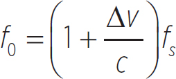
where Δv is the difference in velocities, c is the speed of light, and fs is the natural frequency of the light. Δv is positive when the source and observer are getting closer together, and it is negative when they are getting farther apart.
EXAMPLE 
You know that a distant star should be emitting light at a wavelength of 656.281 nm (known as the hydrogen-alpha line), but when you look for light at this wavelength, you don’t find it anywhere. However, you do notice that you are receiving light from the star at a wavelength of 656.303 nm, which you conclude must be the hydrogen-alpha line. What is the relative motion between the Earth and this distant star?
You can change Equation 14.4 so you can compare wavelengths, rather than frequencies:
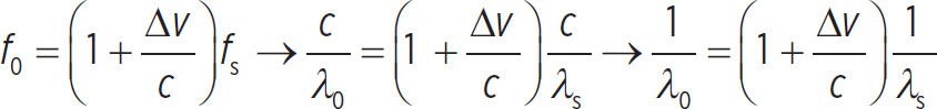
Now, if you want to know about the motion between the Earth and this distant star, you need to solve for Δv:
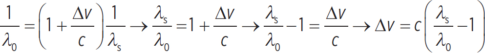
So, using the numbers provided in the question, you see that the relative motion between the Earth and this star is
Δv = 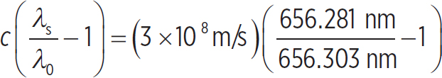 = −10,056 m/s
So the distant star is moving at about 10 km/s away from the Earth.

When light approaches a boundary between two media, it can do one of two things: It can be reflected off the boundary, or it can pass through the boundary. A mirror, for instance, will allow light to be reflected only off the mirror, a clear substance will allow light to transmit only through the boundary, and a translucent or transparent substance, like glass, will allow light to both reflect and transmit. If you look through glass, you often will see your own reflection as well as whatever is on the other side of the glass.
Light will always travel in a straight line. This is due to the fact that light has no mass, so a force cannot act on light to change its direction. However, when light encounters a boundary between media, its path will change. The following figure shows the change in the path of light for reflection off, and transmission through, a boundary.
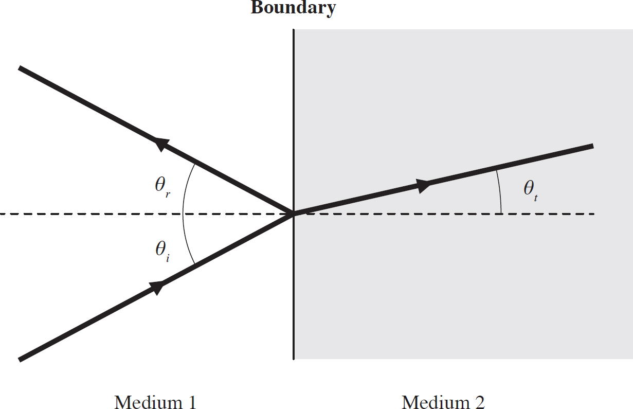
Figure 14.5: Reflection and Transmission at a Boundary
The reflection of light off a boundary is identical to an elastic collision of an object and a surface that doesn’t move (a ball that bounces off the floor, for instance). In this case, the incident angle θi is equal to the reflected angle θr:
Equation 14.5
θi = θr
This is known as the Law of Reflection. In this case it doesn’t matter, but the angles are measured with respect to the normal of the boundary, as indicated in Figure 14.5.
EXAMPLE 
In the following figure, a light ray is incident on a highly reflective surface at an angle of 30° to the normal. Undergoing the reflective process described, solve for the lengths w, d, and each indicated angle.

First identify the values of the first two angles. Notice that θ1 must equal 30°, according to the Law of Reflection. This means that θ2 must equal 60°. Now you have a triangle of angle 60°, with an adjacent length of 8.5 cm and an opposite edge of w. This means
tan(60½) =  → W = (8.5 cm)tan(60½) = 14.7 cm
Also notice that the hypotenuse of this triangle is just d. So,
 = 17 cm
Now all you have left is to find the other two angles. Notice that θ2 and θ3 are alternating interior angles, meaning θ3 has to equal 60° as well. So, θ4 is 60°, according to the Law of Reflection.

When light is transmitted, though, the angle changes based on the properties of the media via a process known as refraction. Each medium is specified by its index of refraction, n. Snell’s Law tells us how the transmitted angle relates to the incident angle:
Equation 14.6
ni sin θi = nt sin θt
where ni is the index of refraction for the incident medium and nt is the index of refraction for the transmitted medium. These angles have to be measured from the normal to the surface as well. While this fact didn’t matter in the law of reflection, it does matter in Snell’s Law. The index of refraction, n, gets its name because it is important in determining the degree to which light is refracted at a boundary.
EXAMPLE 
Light in air is incident on the surface of vegetable oil at an angle of 30° from the normal. Light in air is incident at an angle of 30° on vegetable oil which is 5 cm deep. After passing through the oil, the light passes into water, which is 8 cm deep. If the index of refraction of the oil is 1.47 and the index of refraction of water is 1.33, what is the horizontal distance the light travels before it hits the bottom of the container? The process is illustrated in the following figure.
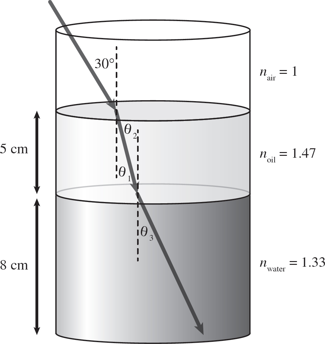
In order to find the total horizontal distance the light travels, we need to know the horizontal distance it travels in the oil as well as in the water. In order to find the horizontal distance it travels in the oil, we need to find the refracted angle as the light passes into the oil. This is done using Snell’s Law:
nair sin(30°) = noil sin(θ1) → sin θ1 =  sin(30°) =
  (0.5) = 0.376 → θ1 = 22.1°
If the oil is 5 cm deep, and it travels a horizontal distance x1 in the oil, you can say
tan(θ1) =  → x1 = (5 cm)tan(22.1°) = 2.0 cm
Now, as the light passes into the water, what is the incident angle at the oil-water boundary? Well, notice that θ1 and θ2 are alternating interior angles. This means that θ2 is just 22.1°, and so the refracted angle of the light in the water is
noil sin(22.1°) = nwater sin θ3 =  sin(22.1°) = 0.416
So, θ3 = 24.6°. If the water is 8 cm deep, and it travels a horizontal distance x2 in the water, you can say
tan θ3 =  → x2 = (8 cm)tan θ3 = (8 cm)tan(24.6°) = 3.7 cm
So the light travels a total horizontal distance of
xtot = x1 + x2 = 2.0 cm + 3.7 cm = 5.7 cm

Consider the previous example. When the light ray passed from the air into the oil, its angle decreased, but when light passed from the oil into the water, its angle increased. This is actually something that always happens. Whenever a ray passes from a medium of lower index of refraction into a medium of higher index of refraction, the angle decreases. Whenever a ray passes from a medium of higher index of refraction into a medium of lower index of refraction, the angle increases.
There is something else that is interesting about Snell’s Law. Let’s say that a ray passes from a medium where the index is n1 to a medium where the index is n2, with an incident angle of θ1 and a refracted angle of θ2. Solving for θ2, we get

Sine has a range of −1 to 1. Within the first quadrant (angles of 0o to 90o), sine has a range of 0 to 1. Notice that if n1 < n2, then the above equation holds for any angle θ1, because the number on the right-hand side will always be less than 1. However, if n1 > n2, there’s no guarantee that the right-hand side of the above equation is going to be 1 or less. A very easy example is n1 = 4, n2 = 1, and θ1 = 30o. In this case the right hand side of the above equation is
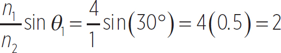
Notice, then, that Snell’s Law can never be satisfied for these conditions, because 2 is out of the range of sine. Thus, transmission of the light is impossible under these conditions; only reflection can occur. This process is known as total internal reflection. When a light ray passes from a medium of higher index of refraction to a medium of lower index of refraction, there is a maximum incident angle that transmission can occur. At angles larger than this maximum angle, only reflection can occur.
If we say that the largest output of sin θ2 is 1, then

This gives us the largest angle at which transmission can occur, θmax:
Equation 14.7

EXAMPLE 
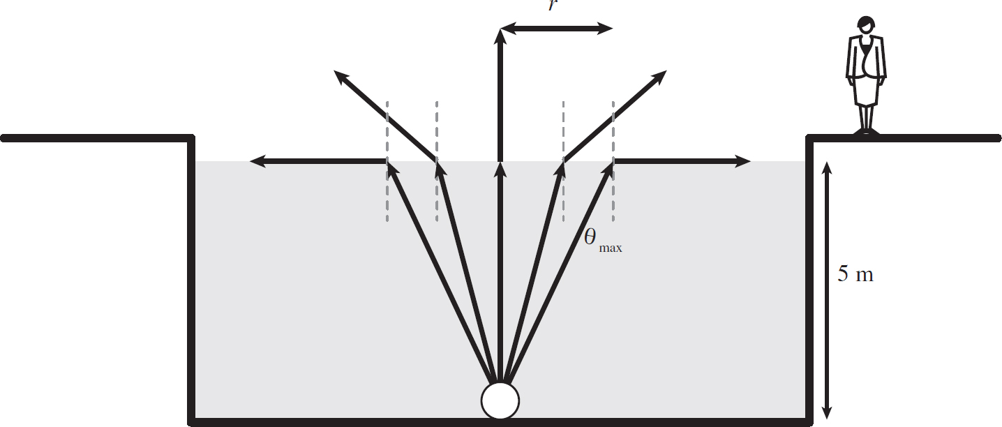
You stand on the edge of a body of water that is 5 m deep. If a light bulb were at the bottom of the body of water, it would emit light in all directions, but you will see only light that can transmit from the water into the air. Since the water is of a higher index of refraction than air, this means there exists a maximum angle at which light can pass into the air. So, the light that you can see from outside the water is restricted to a circle. What is the radius of this circle? Note that nwater = 1.33.
In this problem, light rays are trying to travel from water, of index 1.33, to air, of index 1. This means that there exists a maximum angle after which light can only be reflected off of the surface back down; it can no longer escape. This maximum angle is

So, if the body of water is 5 m deep, then the circle at the surface of the water that light can escape from is of radius
tan θmax =  → r = (5 m)tan(48.8°) = 5.7 m
This is illustrated in the following figure.

Lesson 14.2
Optics
There are two optical systems that we are going to discuss in this section: mirrors and lenses. First, let’s discuss mirrors. We are going to restrict our discussion to spherical mirrors. The term spherical mirror doesn’t mean that the mirror is a sphere itself, but rather the mirror is in the shape of a piece of a sphere. This is illustrated in the following figure.

Figure 14.6: Spherical Mirror
As you can see, the mirror represents a piece of a sphere, rather than the whole sphere itself. We can define the radius of curvature of the mirror as the radius of the sphere the mirror would belong to. In the case of Figure 14.6, this radius of curvature was just r.
Any ray of light that encounters this mirror is going to be reflected back off the surface. We are going to consider 100% of the light as being reflected; none of it can transmit. If we were to shine initially parallel light (known as collimated light) at the mirror, an interesting thing happens. All of the light, once reflected off the mirror, meets at a single point. This is illustrated in the next figure.

Figure 14.7: Collimated Light Reflected Off a Spherical Mirror
The point at which all of the rays of light meet is known as the focus of the mirror, and the distance from the edge of the mirror to the focus is known as the focal length, f. Geometrically, the focal length is related to the radius of curvature of the mirror. If the radius of curvature is R, then the focal length is
Equation 14.8
f = 
Now we want to consider what happens when non-collimated light reflects off the mirror. In this case, we will consider this light as coming off an object a distance so away from the mirror. This is illustrated in the figure on the next page.

Figure 14.8: Image Production with Mirror
The light leaving the object encounters the mirror and then focuses a distance si away from the mirror. This focusing of light rays is known as a real image. When our eyes see an image, they see light leaving from the focus point, and it looks the same to us as light leaving from the object.
In Figure 14.8, we considered light coming off only the top of the object. It turns out that if we consider two points on an object, we see that the image is both inverted (upside-down) and has a smaller height than the object. This is shown in Figure 14.9.
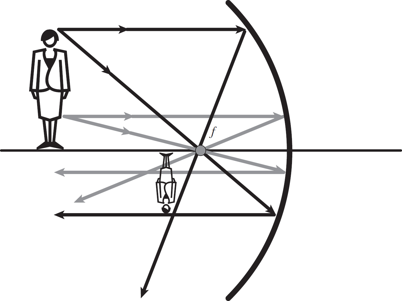
Figure 14.9: An Inverted Image Produced by a Mirror
So far the only type of mirror we have been considering is a concave mirror. What about a convex mirror? We will still consider the mirror to be spherical, with a radius of curvature R. We now want to shine collimated light on the convex mirror. We will see that there will also be a focus at a length R/2, as before, except this time the light doesn’t actually focus on the point—it only appears to focus on this point. This is illustrated in the next figure.

Figure 14.10: Focus of a Convex Mirror
Remember that light travels in a straight line, so the light, after it leaves the mirror, appears to have left the focus point, f. Now, if we consider an object at a distance so from the mirror, the mirror will not produce a real image. A convex mirror can never produce a real image because light leaving the surface of the mirror is always divergent (moving apart). Light leaving the surface of a concave mirror is convergent (coming together), so it can focus, but this is not possible with a convex mirror. However, a convex mirror can produce an apparent image, known as a virtual image. There appears to be an image located si from the mirror. This is illustrated in the following figure.

Figure 14.11: Virtual Image Produced by a Convex Mirror
Your eyes cannot tell the difference between a real image and a virtual one. Your brain interprets light as always moving in a straight line, so it sees where the light appears to have come from. It turns out that this virtual image is upright, and of a smaller height.
Now that we have discussed mirrors, we can move on to lenses. Lenses allow the transmission of light through them, unlike mirrors, which allow only reflection. In the case of an ideal lens, light will be 100% transmitted; no light will be reflected. Unlike mirrors, lenses are typically made up of two surfaces. We are going to consider spherical lenses just like we considered spherical mirrors.
If we shine collimated light on a lens composed of two spherical, convex pieces of glass (referred to as a convex or biconvex lens), we will see that light is focused on a point, just like with mirrors. This is illustrated in the following figure.

Figure 14.12: Collimated Light Through Converging Lens
As illustrated in Figure 14.2, light passing through a biconvex lens converges on a point, the focus, so these lenses are typically referred to as converging lenses. As with mirrors, the distance from the lens to the focus is still referred to as the focal length, f. For lenses composed of two spherical surfaces with radius of curvature R, the focal length is R/2, as with mirrors. Because light can be shone through both sides of the lens, there is a focal point on both sides, at the same distance R/2.
Now, converging lenses can be used to form images. This is illustrated in the figure below.

Figure 14.13: Image Formed by a Converging Lens
An image formed by a converging lens is a real image because it is formed by the actual convergence of light on a focus. Notice that the real image is also inverted, as was the case of a concave mirror. In fact, all real images are inverted.
What about a lens formed with two concave surfaces (referred to as a concave or biconcave lens)? Well, if we shine collimated light through one, the light will diverge rather than converge. Because of this, light never actually focuses, but there is an apparent focus. This is identical to the concept of an apparent focus in a convex mirror, and it is illustrated in the following figure.

Figure 14.14: Collimated Light Through Diverging Lens
These lenses cause light to diverge, so they are typically referred to as diverging lenses. Diverging lenses can produce virtual images in the same manner as convex mirrors, as illustrated in the Figure 14.15.
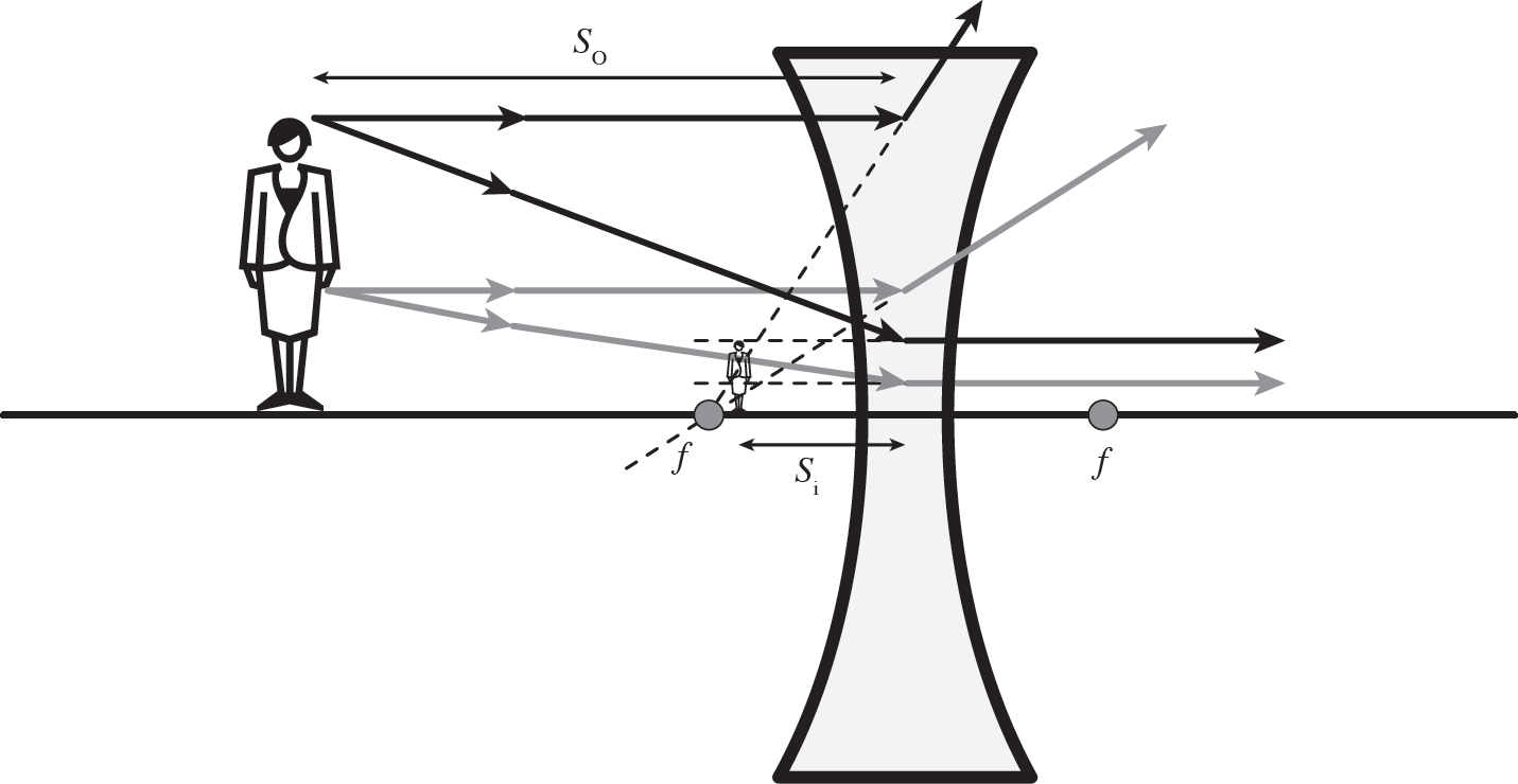
Figure 14.15: Image Formed by a Diverging Lens
As illustrated in the figure above, the virtual image is upright, the same as it was in the case of a convex mirror. It turns out that all virtual images are upright, like all real images are inverted.
Everything done up to this point in this section has been done with what are referred to as ray diagrams. Ray diagrams are geometric diagrams that can show you the exact position and height of an image if you draw them properly using rulers, protractors, etc. The fact is that the images are produced purely as a byproduct of geometry, which is why this is typically referred to as geometric optics.
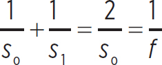
However, we want to move away from using ray diagrams as they are unreliable unless drawn perfectly. Using math is much more reliable, so we want to introduce the equation that governs the position of an image formed by an optical system. This is known as the thin lens equation, or the lens maker’s equation:
Equation 14.9

so, si and f are exactly as we defined them previously: the object distance, the image distance, and the focal length, respectively. Even though this equation is called the thin lens equation, it works just as well for mirrors. Remember that for spherical objects, the focal length is R/2.
All we need is Equation 14.9 to find exactly where the image is located for any spherical mirror or lens. The only other piece of information needed is the height of the image. The magnification of an image is given by the following equation:
Equation 14.10
m = 
Sometimes this equation is given with a negative sign, but it is not necessary. The magnification just tells us the ratio of the image height to the object’s height. For instance, a magnification of 2 means that the image is twice as tall as the object.
There are a few things that we have to establish before using the thin lens equation. First, for converging systems (concave mirrors and converging lenses), the focal lengths are positive, but for diverging systems (convex mirrors and diverging lenses), the focal lengths are negative. The object distance, so, is positive for all optical systems. Next, if an image is real, it will have a positive image distance, si. If an image is virtual, it will have a negative image distance.
As mentioned in the previous paragraph, sometimes the magnification is given with a negative sign. All this means is that if you have a real image, which has a positive image distance, the magnification is negative, indicating that the image is inverted. For a virtual image, which has a negative image distance, the magnification will be positive, so the image will be upright. It is simpler to just remember the fact that all real images are inverted and all virtual images are upright; ignore the sign of the magnification.
EXAMPLE 
A converging lens is made of two pieces of glass with a radius of curvature of 12 cm. If a 2 cm tall object is placed 10 cm from the lens, where will the image be produced? Will this be a real or virtual image? Will it be upright or inverted? What is the height of the image?
All you need to do is apply these numbers to the thin lens equation. First, find the focal length of the lens:
f =  = 6 cm
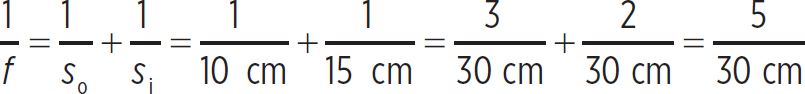
Since this is a converging lens, the focal length is positive. Now find the image distance:
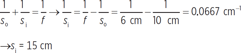
So, the image is at +15 cm, which means that it is real. Since it is real, it is inverted (this is always so). Lastly, you need to find the height of the image. To do so, you need to find the magnification:
m =  = 1.5
= 1.5
So the image is 1.5 times taller than the object, or 3 cm.

EXAMPLE 
What types of images can a diverging system produce? What types of images can a converging system produce? Show with the thin lens equation.
You already know that all diverging systems can produce only virtual images. It is impossible for a diverging system to produce a real image because light diverges after encountering the system. Thus, light can never focus because it is spreading apart. We can show this using the thin lens equation. The image distance will be

Since the focal length of a diverging system is negative, and the object distance is positive by definition, the image distance can only be negative (a negative number minus a positive number is always negative). This means that the only images a diverging system can produce are virtual, as you knew.
Now, for a converging system it’s a little more complicated. The focal length is positive, so you have a positive number minus a positive number, which can be either positive or negative. If 1/f is larger than 1/so, then the image distance is positive, and the image is real. Another way of saying this is if f is smaller than so, then the image is real. If 1/f is smaller than 1/si, then the image distance is negative, and the image is virtual. Another way of saying this is that if f is larger than so, the image is virtual. So, if the object is outside of the focus of a converging system, all images produced are real. But if the object is within the focus of a converging system, then all images produced are virtual. Notice that when we presented the ray diagrams for our two converging systems, the concave mirror and the converging lens, the object was outside of the focus both times.

EXAMPLE 
A lens has a focal length of 5 cm. How far do you have to position the object so that the image produced is the same height as the object?
In this case, you want the magnification to be 1. In order for this to be so, so must equal si. So, our thin lens equation becomes
or
so = 2f = 2(5 cm) = 10 cm

Optical systems are very straightforward to solve if you take the time to learn the material. All one has to do is set up the thin lens equation and solve for the missing variable. The only other things to figure out are the focal length from the radius of curvature and the magnification of an image.
DRILL
CHAPTER 14 PRACTICE QUESTIONS
Click here to download a PDF of Chapter 14 Practice Questions.
Directions: Complete the following problems as specified by each question, and then check your work using the solutions that follow. For extended, step-by-step solutions, access your Student Tools online.
1. Blue light of wavelength 450 nm passes from a vacuum into water, where the index of refraction is 1.33. What is the wavelength of the light in water?
2. Consider a light bulb emitting light at a wavelength of 650 nm. How fast would you have to be moving so that the light bulb appeared to be emitting blue light of wavelength 660 nm? Would you have to be moving toward or away from the bulb?
3. Light passes from air into a medium of unknown index of refraction. The light then passes from this unknown medium into water, where the index of refraction is 1.33. If the light was incident on the unknown medium at an angle of 45°, what is the angle of the light when it enters the water?
4. Light passes from air into an oil of index of refraction 1.47. What is the largest incident angle at which transmission of the light occurs?
5. Light passes from a medium of unknown index of refraction into water. If the maximum angle at which light can still transmit is 35°, what is the index of refraction of the unknown medium?
6. A concave mirror is formed with a piece of reflective glass that has a radius of curvature of 5 cm. If you shine collimated light at the mirror, how far away from the mirror’s surface will this light focus?
7. An object is placed 10 cm away from a concave mirror, producing an image 5 cm behind the object. What is the focal length of the mirror?
8. A diverging lens is produced by using two spherical pieces of glass, each with a radius of curvature of 10 cm. If a 4 cm tall object is placed 10 cm in front of the lens, where is the image produced? Is it produced in front or behind the lens? How tall is the image?
SOLUTIONS TO CHAPTER 14 PRACTICE QUESTIONS
1. The frequency of the light in a vacuum is
f =  = 6.7 × 10¹⁴ Hz
You know that the frequency of the light has to remain constant as it passes into the water. The speed of light in water is
v =  = 2.25 × 10⁸ m/s
so the wavelength of the light in water is
λ′ = 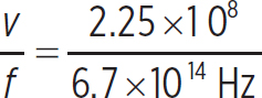 = 336 nm
2. The equation for the Doppler effect is
f0 = 
So, you can say that
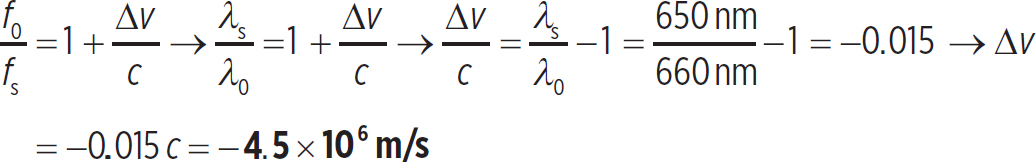
So you would have to be moving away from the light bulb at 4,500 km/s to produce this change in wavelength.
3. Snell’s Law for the first transition says
n1 sin θ1 = n2 sin θ2
Since n2, the index of refraction of the second medium is unknown, you cannot solve this equation. But, Snell’s Law for the second transition says
n2 sin θ2 = n3 sin θ3
which means
n1 sin θ1 = n2 sin θ2 = n3 sin θ3
Since you know n3, the index of refraction of the water, you can solve for θ3, the angle of the light ray after it has passed into the water:
sin θ3 =  sin θ1 =
  sin (45½) = 0.532
This means that the angle in the water is 32°.
4. The light is passing from air, which has an index of 1, into oil, which has an index of 1.47. This means that there is no maximum angle past which transmission cannot occur. Total internal reflection occurs only when light passes from a medium of higher index into a medium of lower index.
5. Using our equation for total internal reflection,
sin θmax = 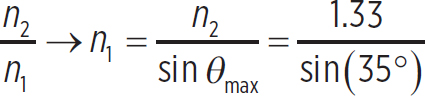 = 2.32
6. The distance from the surface of the mirror that collimated light will focus is the definition of the focal length. For a spherical mirror, this is simply
f =  = 2.5 cm
7. If the image is produced 5 cm behind the object, it is a distance of 15 cm from the mirror. Thus,
So the focal length is just 30 cm/5 = 6 cm.
8. First, the focal length of this lens is
f = − = −5 cm
Note that the focal length is negative because it is a diverging lens. If the object distance is 10 cm, then
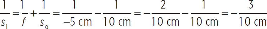
So the image distance is
Si = − = −3.3 cm
Since this is a virtual image (it has a negative image distance), it is produced on the same side of the lens as the object, so it is produced in front of the lens. The magnification of the image is
m =  = 0.33
So the height of the image is 0.33 times the height of the object, or 1.33 cm.
REFLECT
Congratulations on completing Chapter 14!
Here’s what we just covered.
Rate your confidence in your ability to:
• Define light and describe the electromagnetic spectrum
1 2 3 4 5
• Describe how light acts at a boundary between two media
1 2 3 4 5
• Calculate the angle of refraction for light passing between two media
1 2 3 4 5
• Explain how optical systems produce real and virtual images
1 2 3 4 5
• Calculate the positions of real and virtual images produced by optical systems using the thin lens equation
1 2 3 4 5
If you rated any of these topics lower than you’d like, consider reviewing the corresponding lesson before moving on, especially if you found yourself unable to correctly answer one of the related end-of-chapter questions.