Three-phase circuits are important because almost all electric power is generated and distributed three-phase. A three-phase circuit has an ac voltage generator, also called an alternator, that produces three sinusoidal voltages that are identical except for a phase angle difference of 120°. The electric energy is transmitted over either three of four wires, more often called lines. Most of the three-phase circuits presented in this chapter are balanced. In them, three of the line currents are identical except for a phase angle difference of 120°.
The polarities of voltages in three-phase circuits are designated by double subscripts, as in VAB. As may be recalled from Chap. 1, these subscripts identify the nodes that a voltage is across. Also, the order gives the voltage reference polarity. Specifically, the first subscript specifies the positively referenced node and the second subscript the negatively referenced node. So, VAB is a voltage drop from node A to node B. Also, VAB = –VBA.
Double subscripts are also necessary for some current quantity symbols, as in IAB. These subscripts identify the nodes between which IAB flows, and the order of the subscripts specifies the current reference direction. Specifically, the current reference direction is from the node of the first subscript to the node of the second subscript. So, the current IAB has a reference direction from node A to node B. Also, IAB = –IBA. Figure 17-1 illustrates the subscript convention for IAB and also for IAB.
Double subscript notation is also used for some impedances, as in ZAB. The subscripts identify the two nodes that the impedance is connected between. But the order of the subscripts has no significance. Consequently, ZAB = ZBA.
Fig. 17-1
Figure 17-2a is a cross-sectional view of a three-phase alternator having a stationary stator and a counterclockwise rotating rotor. Physically displaced by 120° around the inner periphery of the stator are three sets of armature windings with terminals A and A ′, B and B ′, and C and C′. It is in these windings that the three-phase sinusoidal voltages are generated. The rotor has a field winding in which the flow of a dc current produces a magnetic field.
As the rotor rotates counterclockwise at 3600 r/min, its magnetic field cuts the armature windings, thereby inducing in them the sinusoidal voltages shown in Fig. 17-2b. These voltages have peaks at one-third of a period apart, or 120° apart, because of the 120° spatial displacement of the armature windings. As a result, the alternator produces three voltages of the same rms value, which may be as great as 30 kV, and of the same frequency (60 Hz), but phase-shifted by 120°. These voltages might be, for example,
Fig. 17-2

and

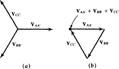
If the voltages shown in Fig. 11-2b are evaluated at any one time, it will be found that they add to zero. This zero sum can also be shown by vector graphical addition of the phasors corresponding to these voltages. Figure 17-3a is a phasor diagram of the three phasors VAA′, VBB′, and VCC′, corresponding to the generated voltages. These three phasors are added in Fig. 17-3b by connecting the tail of VBB. to the tip of VAA′, and the tail of VCC to the tip of VBB. Since the tip of VCC. touches the tail of VAA, the sum is zero. And since the sum of the phasor voltages is zero, the sum of the corresponding instantaneous voltages is zero for all times.
Fig. 17-3
In general, three sinusoids have a sum of zero if they have the same frequency and peak value but are phase-displaced by 120°. This is true regardless of what, if anything, that the sinusoids correspond to. In particular, it is true for currents.
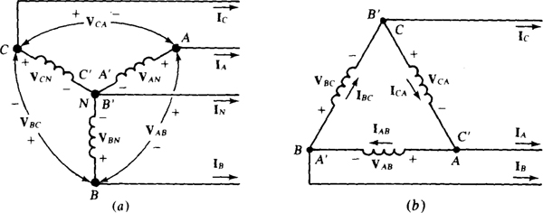
The ends of the generator windings are connected together to decrease the number of lines required for connections to loads. The primed terminals can be connected together to form the Y (wye) shown in Fig. 17-4a, or primed terminals can be connected to unprimed terminals to form the Δ (delta) shown in Fig. 17-4b). The primed letters are included this once to show these connections. But since the terminals at which they are located also have unprimed letters, the primed letters are not necessary. These Y and Δ connections are not limited to generator windings but apply as well to transformer windings and load impedances. There are some practical reasons for preferring the Y connection for alternator windings, but both the Y and Δ connections are used for transformer windings and for load impedances. Incidentally, in circuit diagrams, sometimes circular ac generator symbols are used instead of the coil symbols.
Fig. 17-4
In the Y connection shown in Fig. 17-4a, the primed terminals are joined at a common terminal marked N for neutral. There may be a line connected to this terminal, as shown, in which case there are four wires or lines. If no wire is connected to the neutral, the circuit is a three-wire circuit. The Δ connection illustrated in Fig. 17-4b inherently results in a three-wire circuit because there is no neutral terminal.
For the Y connection, the line currents, are also the winding currents, also called phase currents. A line current is a current in one of the lines and by convention is referenced from the source to the load. A phase current is a current in a generator or transformer winding or in a single load impedance, which is also called a phase of the load.
A Y connection of windings or of impedances has two sets of voltages. There are the voltages VAN, VBN, and VCA, from terminals A, B, and C to the neutral terminal N. These are phase voltages. These differ from the line-to-line voltages, or just line voltages, VAB, VBC, and VCA, across terminals A, B, and C. There are three other line voltages that have a 120° angle difference. These are VAC, VBA, and VCB, which are the negatives of the other line voltages. In each set of line voltages, no two subscripts begin or end with the same letter. Also, no two pairs of subscripts have the same letters.
For the Δ shown in Fig. 17-4b, the line voltages are the same as the phase voltages. But the line currents IA, IB, and Ic differ from the phase currents IAB, IBC, and ICA that flow through the windings. There is another suitable set of phase currents: IAC, IBA, and ICB, which are the negatives of the currents in the first set.
The phase sequence of a three-phase circuit is the order in which the voltages or currents attain their maxima. For an illustration, Fig. 17-2b shows that vAA peaks first, then vBB, then vcc, then vAA, etc., which is in the order of … ABC ABC AB …. Any three adjacent letters can be selected to designate the phase sequence, but usually the three selected are ABC. This is sometimes called the positive phase sequence. If in Fig. 17-2a the labels of two windings are interchanged, or if the rotor is rotated clockwise instead of counterclockwise, the phase sequence is ACB (or CBA or BAC), also called the negative phase sequence. Although this explanation of phase sequence has been with respect to voltage peaking, phase sequence applies as well to current peaking.
Phase sequence can be related to the subscripts of voltage and current phasors. If, for example, VAN has an angle 120° greater than that of VBN, then vAN must lead vBN by 120°, and so the phase sequence must be ABC. Incidentally, the terms “lead” and “lag” are often applied to the voltage phasors as well as to the corresponding instantaneous voltages. For another example, if VCN leads VBN by 120°, then in the phase sequence the first subscript C of VCN must be immediately ahead of the first subscript B of VBN. Consequently, the phase sequence is CBA, or ACB, the negative phase sequence.
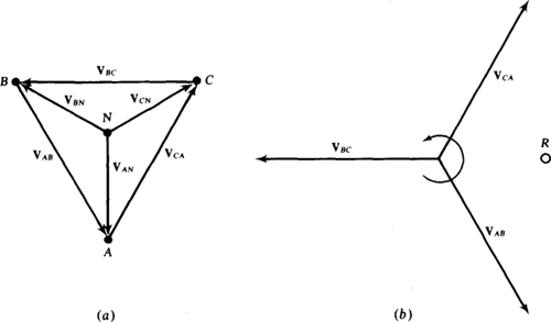
Phase sequence can be related to either the first or second subscripts of the line voltage phasors. This can be verified with an example. Figure 17-5a shows a phasor diagram of phase voltages VAN, VBN, and VCN for an ABC phase sequence. Also included are terminals A, B, C, and N positioned such that lines drawn between them give the correct corresponding phasors. Drawn between terminals A, B, and C are a set of line voltage phasors: VAB, VBC, and VCA, which are redrawn in the phasor diagram shown in Fig. 17-5b. Note that VAB leads VBC by 120° and that VBC leads VCA by 120°. On the basis of this leading, the order of the first set of subscripts is ABC, in agreement with the phase sequence. The order of the second set of subscripts is BCA, which is equivalent to ABC, also in agreement with the phase sequence. This order can also be found by using a reference point R on the phasor diagram, as shown. If the phasors are rotated counterclockwise about the origin, the first subscripts pass the reference point in the order of the phase sequence, as do the second subscripts.
Fig. 17-5
In a similar manner it can be shown for a balanced circuit that the line current phasor subscripts correspond to the phase sequence order in the same way as explained for the voltage phasor subscripts. Also, the same is true for either the first or the second subscripts of the phase current phasors for a balanced Δ load. (A balanced Δ load has three equal impedances.)
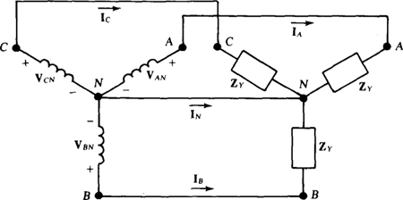
Figure 17-6 shows a balanced Y circuit that has a balanced Y load (a Y load of identical impedances) energized by a generator having Y-connected windings. Instead of generator windings, the windings could as well be the secondary windings of a three-phase transformer. A neutral wire connects the two neutral nodes.
A balanced three-phase circuit is easy to analyze because it is, in effect, three interconnected but separate circuits in which the only difference in responses is an angle difference of 120°. The general analysis procedure is to find the desired voltage or current in one phase, and use it with the phase sequence to obtain the corresponding voltages or currents in the two other phases. For example, in the circuit shown in Fig. 17-6, the line current IA can be found from IA = VAN/ZY. Then, IB and Ic can be found from VA and the phase sequence: They have the same magnitude as IA, but lead and lag IA by 120° as determined from the phase sequence.
Fig. 17-6
Since the three currents IA, IB, and Ic have the same magnitude but a 120° angle difference, their sum is zero: IA + IB + Ic = 0. And from KCL, IN = — (IA + IB + Ic) = 0 A. Because the neutral wire carries no current, it can be eliminated to change the circuit from a four-wire to a three-wire circuit. A further consequence of the zero neutral current is that the two neutral nodes are at the same potential, even without the neutral wire. In practice, though, it may be a good idea to have a small neutral wire to ensure balanced phase voltages in case the load impedances are not exactly the same.
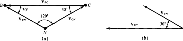
The set of phase voltages and either set of line voltages for a balanced Y load have certain angle and magnitude relations that are independent of the load impedance. These relations can be obtained from one of the triangles shown in Fig. 17-5a. Consider the triangle formed by VBN, VCN, and VBC. The largest angle is 120°, leaving 180° — 120° = 60’ for the other two angles. Since these two are opposite sides of equal length, they must be equal and so 30° each as shown in Fig. 17-7a. It can be seen that there is a 30° angle between line voltage VBC and phase voltage VBN, as is better shown in Fig. 17-7b. As should be evident from Fig. 17-5a, there is also a 30” angle difference between VAB and VAN and between VCA and VCN. In general, in the voltage phasor diagram for a balanced Y load, there is a 30” angle between each phase voltage and the nearest line voltage. This 30° can be either a lead or a lag, depending on the particular set of line voltages and also the phase sequence.
Fig. 17-7
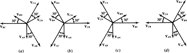
Figure 17-8 has all the possible phasor diagrams that relate the Y phase voltages and the two sets of line voltages for the two phase sequences. Thus, all angle relations between the line and Y phase voltages can be determined from them. From the subscripts it should be apparent that Figs. 17-8a and b are for an ABC phase sequence and Figs. 17-8c and d are for an ACB phase sequence. Only relative angles are shown. For actual angles, the appropriate diagram would have to be rotated until any one phasor is at its specified angle, but this is seldom necessary.
Fig. 17-8
There is also a relation between the magnitudes of the line and phase voltages. From Fig. 17-7a and the law of sines,
or 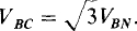 In general, for a balanced Y load the line voltage magnitude VL is
  times Vp, the phase voltage magnitude:
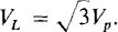
Incidentally, in the description of a three-phase circuit the specified voltage should be assumed to be the rms line-to-line voltage.
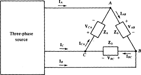
Figure 17-9 shows a balanced A load connected by three wires to a three-phase source. As a practical matter, this source is either a Y-connected alternator or, more probably, a Y- or Δ-connected secondary of a three-phase transformer. There is, of course, no neutral wire because a Δ load has only three terminals.
Fig. 17-9
The general procedure for finding the A phase currents is to first find one phase current and then use it with the phase sequence to find the other two. For example, the phase current IAB can be found from IAB = VAB/ZΔ and then IBC and VCA from VAB and the phase sequence: These have the same magnitude as IAB, but lead and lag IAB by 120° as determined from the phase sequence.
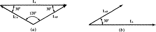
The set of line currents and either set of phase currents for a balanced Δ have certain angle and magnitude relations that are independent of the load impedance. These can be found by applying KCL at any terminal in the circuit shown in Fig. 17-9. If done at terminal A, the result is IA = IAB — ICA. Figure 17-10a is a graphical representation of this subtraction for an ABC phase sequence. Since this is the same form of triangle as for the phase and line voltages of a balanced Y load, the results are similar: On a phasor diagram there is a 30° angle difference between each phase current and the nearest line current, as shown in Fig. 17-10b. This 30° can be either a lead or a lag, depending on the particular set of phase currents and on the phase sequence. Also, the line current magnitude IL is times Ip, the phase current magnitude: 
Fig. 17-10
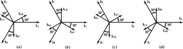
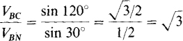
Figure 17-11 has all the possible phasor diagrams that relate the line currents and the two sets of phase currents of balanced A loads for the two phase sequences. Thus all angle relations between the line and A phase currents can be determined from them. From the subscripts it should be evident that Figs. 17-1 la and b are for an ABC phase sequence and that Figs. 17-1 lc and d are for an ACB phase sequence. Only relative angles are shown. For actual angles, the appropriate diagram would have to be rotated until any one phasor is at its specified angle, but this is seldom necessary.
Fig. 17-11
If a three-phase circuit has several loads connected in parallel, a good first step in an analysis is to combine the loads into a single Y or Δ load. Then, the analysis methods for a single Y or Δ load can be used. This combining is probably most obvious for two A loads, as shown in Fig. 17-12a. Being in parallel, corresponding phase impedances of the two Δ’s can be combined to produce a single equivalent Δ.
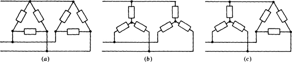
If there are two Y loads, as shown in Fig. 17-12b, and if there is a neutral wire (not shown) connecting the two neutral nodes of the loads, corresponding phase impedances of the two Δ’s are in parallel and can be combined to produce a single equivalent Y. Even if there is no neutral wire, the corresponding phase impedances are in parallel provided that both Y loads are balanced because then both neutral nodes are at the same potential. If the loads are unbalanced and there is no neutral wire, corresponding impedances of the two Y’s are not in parallel. Then, the two Δ’s can be transformed to two Δ's, and these combined into a single equivalent Δ.
Sometimes a three-phase circuit has a Y load and a Δ load, as shown in Fig. 17-12c. If the loads are balanced, the A can be transformed to a Y and then the two Y’s combined. If the loads are unbalanced, the Y can be transformed to a Δ and then the two Δ’s combined into a single equivalent Δ.
The average power absorbed by a balanced three-phase Y or Δ load is, of course, just three times the average power absorbed by any one of the phase impedances. For either a balanced Δ or a Y load, this is P = 3 VpIp cos θ. The power formula is usually expressed in terms of the rms line voltage VL and the rms line current IL. For a Y load, Vp = VL/ and Ip = IL. And for a A load, Vp = VL and Ip = IL/. With either substitution the result is the same:
which is the formula for the total average power absorbed by either a balanced Y or Δ load. It is important to remember that θ is the load impedance angle and not the angle between a line voltage and line current.
Formulas for complex power S and reactive power Q can be readily found using the relations with average power presented in Chap. 15. For a balanced three-phase load, the result is

Three-phase power factor correction is obtained with a balanced Y or Δ of capacitors, with each phase producing one-third of the required reactive power. Consequently, for each phase of a A the capacitance required is
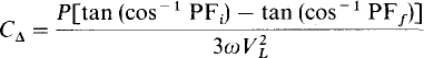
But since for a Y the phase voltage is VL/, the voltage factor in the denominator is  So, the 3s divide out, with the result that
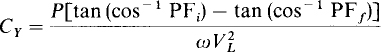
Consequently, for a Y connection of power factor correction capacitors, the capacitance required in each phase is three times that required for a Δ. On the other hand, though, the breakdown voltage requirement is less for the Y-connected capacitors.
If a three-phase load is balanced, the total average power absorbed can be measured by connecting a wattmeter into a single phase and multiplying the wattmeter reading by three. For this, the wattmeter current coil should be connected in series with a phase impedance and the wattmeter potential coil should be connected across this impedance. If the-load is unbalanced, three measurements can be made, one in each phase.
Frequently, though, it is impossible to connect a wattmeter into a phase. This is true, for example, for the common three-phase electric motor that has just three wires extending from it. For such an application, the two-wattmeter method can be used, provided that there are just three wires to a load.
Figure 17-13 shows the wattmeter connections for the two-wattmeter method. Notice that the current coils are in series in two of the lines and that the respective potential coils are connected between these two lines and the third line. The ± terminals are connected such that each wattmeter is connected as if to give an upscale reading for power absorbed by the load.
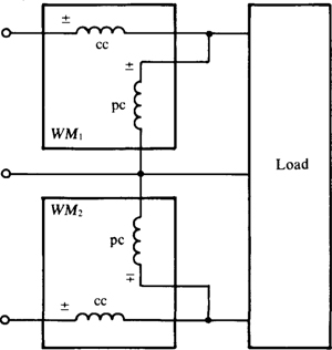
Fig. 17-13
It can be shown that the total average power absorbed by the load is equal to the algebraic sum of the two wattmeter readings. So, if one reading is negative, it is added, sign and all, to the other wattmeter reading. (Of course, it may be necessary to reverse a coil to obtain this reading.) This two-wattmeter method is completely general. The load does not have to be balanced. In fact, the circuit does not have to be three-phase or even sinusoidally excited.
From the line voltage and current phasors, it can be calculated that, for a balanced load with an impedance angle of 0, one wattmeter reading is VL IL cos (30° + 8) and the other is VLIL cos (30° – 0). The wattmeter with the VLIL cos (30° + θ) reading has a current coil in the line corresponding to the phase sequence letter that immediately precedes the letter of the line in which there is no current coil. If, for example, there is no current coil in line C, and if the phase sequence is ABC, then, since B precedes C in the phase sequence, the wattmeter with its current coil in line B has the VL IL cos (30° + θ) reading.
The impedance angle for the phase impedance of a balanced load can be found from the readings of wattmeters connected for the two-wattmeter method. There are six formulas that relate the tangent of the impedance angle to the power readings. The appropriate formula depends on the phase sequence and the lines in which the current coils are connected. If PA, PB, and Pc are the readings of wattmeters with current coils in lines A, B, and C, then, for an ABC phase sequence,
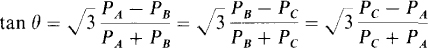
For an ACB phase sequence, tan θ equals the negative of these.
If a three-phase circuit has an unbalanced load, none of the shortcuts for the analysis of balanced three-phase circuits can be used. Conventional mesh or loop analysis is usually preferable. If the load is an unbalanced Y with a neutral wire, then the voltage across each phase impedance is known, which means that each phase current can be readily found. The same is true for an unbalanced A load if there are no line impedances. Otherwise, it may be preferable to transform the A to a Y so that the line impedances are in series with the Y phase impedances.
PSpice applies to the analysis of a three-phase circuit, balanced or unbalanced, as to any ac circuit. There are, however, three special considerations. First, if a Y load has a series-connected capacitor in each phase and if there is no neutral wire, then PSpice will not complete an analysis because there is no dc path from the neutral node of this Y to the 0 node, assuming that this neutral node is not the 0 node. This problem is easily solved by inserting between these two nodes a resistor of extremely large resistance, thus providing the dc path without significantly affecting the analysis.
Second, a Δ-Δ circuit has no convenient node for the 0 node, which may or may not'be important. If it is important, a balanced Y of resistors can be inserted and then the neutral node of this Y used for the 0 node. The resistance of each resistor should be large enough to avoid having the inserted Y affect the results.
Finally, PSpice will not analyze a circuit that has a Δ of voltage sources, inductors, or transformer windings, or a mixture of these. Inserting into this Δ a single resistor of negligibly small resistance will eliminate this problem as regards obtaining external voltages or currents. But if currents are of interest interior to a Δ of voltage sources, it is necessary to insert two other resistors to achieve balance. Otherwise, the obtained source currents will not even be approximately accurate.
Incidentally, for a Δ of voltage sources, one voltage source can be replaced by an open circuit to avoid having a loop of voltage sources. This deletion will not change the line voltages. It will, however, affect the currents flowing in the voltage sources, and so cannot be done if these currents are of interest. Similarly, for a three-phase transformer, if the windings are connected Δ-Δ, one primary winding and the corresponding secondary winding can be replaced by open circuits to avoid having loops of inductors. Electric utilities sometimes use two single-phase transformers in this manner to obtain three-phase transformer action. This is called an open-delta installation, and provides 57.7 percent of the capacity of a three-transformer bank. Utilities often use an open-delta installation when they know that the load will be increased in the future.
17.1 What is the phase sequence of a balanced three-phase circuit in which  and
and  What is VBN?
Since VCN lags VAN by 120°, and the first subscripts are C and A, respectively, C follows A in the phase sequence. So, the phase sequence is ACB, the negative phase sequence. Of course, VB/V leads VAN by 120°, but has the same magnitude:  .
.
17.2 What is the phase sequence of a balanced three-phase circuit in which  and
and  What is VAN?
Since VCN leads VBN by 120°, and the first subscripts are C and B, respectively, C leads B in the phase sequence, which must be CBA, or ACB, the negative phase sequence. Of course, VAN has the same magnitude as VCN, but has an angle that is 120° greater:

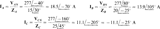
17.3 In a three-phase, three-wire circuit, find the phasor line currents to a balanced Y load in which each phase impedance is  Also,
Also,  , and the phase sequence is ABC.
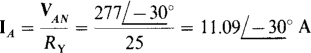
The line current IA can be found by dividing the phase voltage VAN by the phase impedance ZY:
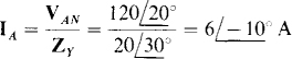
The other line currents can be determined from IA and the phase sequence. They have the same magnitude as IA, and for the specified ABC phase sequence, the currents IB and Ic, respectively, lag and lead IA by 120°. So,
17.4 What is the phase sequence of a three-phase circuit in which and  Also, which line voltage has an angle that differs by 120° from the angles of these voltages?
The phase sequence can be found from the voltage angles and first subscripts. Since VBC leads VAB by 120°, and since the first subscripts are B and A, respectively, B is immediately ahead of A in the phase sequence. So the phase sequence must be BAC or equivalently, ACB, the negative phase sequence.
The third line voltage is either VCA or VAC because only A and C of ABC have not been used together in subscripts. The proper third line voltage—the voltage that has an angle differing by 120° from those of VAB and VBC —is VCA since no two line voltages of a set can have subscripts that start with the same letter, as would be the case if VAC were used. Thus,  This result is also obvious from Fig. 17-8c.
17.5 A balanced three-phase Y load has one phase voltage of  If the phase sequence is ACB, find the line voltages VCA, VAB, and VBC.
From Fig. 17-8c, which is for an ACB phase sequence and the specified line voltages, it can be seen that the line voltage VCA has an angle that is 30° less than that of VCN. Its magnitude is, of course, greater by a factor of So,  Also,
Also,  , from the same figure or from the fact that VAB has an angle that is 120° greater because its first subscript A is just ahead of the first subscript C of VCA in the phase sequence ACB. Similarly, VBC must lag VCA by 120°:
17.6 What are the phase voltages for a balanced three-phase Y load if  The phase sequence is ABC.
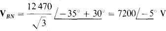
From Fig. 17-8b, which is for an ABC phase sequence and the set of line voltages that includes VBA, it can be seen that VBN leads VBA by 30°. Also, the magnitude of VBN is less by a factor of . So,
Also from this figure, or from the phase sequence and first subscript relation, VAN leads VBN by 120°, and VCN lagsitby 120°:

17.7 A balanced three-phase, three-wire circuit with an ABC phase sequence has one line current of  Find the other line currents.
Because the circuit is balanced, all three line currents have the same magnitude of 20 A. And because the phase sequence is ABC, and A precedes B in the sequence, IA leads IB by 120°. For a similar reason, Ic lags IB by 120°. Consequently,

17.8 What is the IB line current in an unbalanced three-phase, three-wire circuit in which IA =  and
and 
By KCL, the sum of the three line currents is zero: IA, + IB + Ic = 0, from which IB = – IA – Ic = 
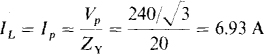
17.9 A balanced Y load of 40-Ω resistors is connected to a 480-V, three-phase, three-wire source. Find the rms line current.
Each line current is equal to the load phase voltage of  divided by the phase impedance of 40 Ω: IL = 277/40 = 6.93 A.
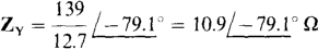
17.10 A balanced Y load of  impedances is energized by a 12 470-V, three-phase, three-wire source. Find the rms line current.
Each line current is equal to the load phase voltage of  divided by the phase impedance magnitude of 50 Ω: IL = 7200/50 = 144 A.
17.11 Find the phasor line currents to a balanced Y load of impedances  energized by a three-phase source. One phase voltage is
  and the phase sequence is ABC.
The line current IB can be found by dividing the phase voltage VBJV by the phase impedance ZY. Then the other line currents can be found from IB with the aid of the phase sequence. The line current IB is
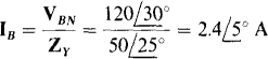
Since the phase sequence is ABC, the angle of IA is 120° more than the angle of IB. Of course, the current magnitudes are the same:  Similarly, the angle of Ic is 120° less. So,
17.12 In a three-phase, three-wire circuit, find the phasor line currents to a balanced Y load for which  and
and  The phase sequence is ABC.
From Fig. 17-8b, the phase voltage VCA, has an angle that is 30° greater than that of VCB and, of course, has a magnitude that is less by a factor of 1/3:
The line current Ic is
Since A follows C in the phase sequence, IA lags Ic by 120°:  . And because B precedes C in the phase sequence, IB leads Ic by 120”:

17.13 What is the phase sequence of a balanced three-phase circuit with a A load in which two of the phase currents are  A and
A and  A? What is IAC?
Since ICB, with a first subscript of C, has an angle 120° greater than that of IBA, which has a first subscript of B, the letter C precedes the letter B in the phase sequence. Thus the phase sequence must be ACB, the negative phase sequence. From this phase sequence, the current IAC, with a first subscript of A, has an angle that is 120° less than that of IBA. Of course, the magnitude is the same. So. 
17.14 Find the phase currents IBC, IAB, and ICA of a balanced three-phase Δ load to which one line current is  The phase sequence is ABC.
From Fig. 17-11a, which is for an ABC phase sequence and the specified set of Δ phase currents, it can be seen that IBC has an angle that is 30° greater than that of IB, and, of course, has a magnitude that is less by a factor of 1/. Consequently,
Also, from the same figure or from the fact that IAB has an angle that is 120° greater because its first subscript A is just ahead of the first subscript B of IBC in the phase sequence ABC,  Then ICA must have an angle that is 120° less than that of IBC. So,
17.15 A balanced three-phase A load has one phase current of  The phase sequence is ACB. Find the other phasor phase currents and also the phasor line currents.
The two other desired phase currents are those having angles that differ by 120° from the angle of IBA. These are IAC and ICB, as can be obtained from the relation of subscripts: No two currents can have the same first or second subscript letters, or the same two letters. This is also obvious from Fig. 17-1 lc. Since the phase sequence is ACB or negative, ICB must lead IBA by 120° because in the phase sequence the letter C, the first subscript letter of ICB, precedes the letter B, the first subscript letter of IBA. Also, Fig. 17-1 lc shows this 120° lead. Therefore,  Then IAC must lag IBA by 120°: IAC =
From Fig. 17-11c, IA lags IAC by 30°, and since it has a magnitude that is greater by a factor of ,  Because the phase sequence is ACB, currents IB and Ic, respectively, lead and lag IA by 120°:

17.16 What are the phasor line currents to a balanced three-phase A load if one phase current is  and if the phase sequence is ABC?
From Fig. 17-11b, which is for an ABC phase sequence and the set of phase currents that includes ICB, it can be seen that Ic leads ICB by 30°. Of course, its magnitude is greater by a factor of . So  A. From the phase sequence, IB leads Ic by 120° and IA lags it by 120°:

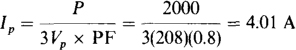
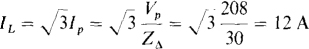
17.17 A 208-V three-phase circuit has a balanced A load of 50-Ω resistors. Find the rms line current.
The rms line current IL can be found from the rms phase current Ip, which is equal to the 208-V line voltage (and also phase voltage) divided by the 50-μ phase resistance: Ip = 208/50 = 4.16 A. The rms line current IL is greater by a factor of
17.18 Find the phasor line currents to a balanced A three-phase load of impedances  if one phase voltage is
  and if the phase sequence is ACB.
A good first step is to find the phase current ICB:
From Fig. 17-1lc, which is for an ACB phase sequence and the set of phase currents that includes ICB, the line current Ic lags ICB by 30°. Of course, its magnitude is greater by a factor of . So

Since the phase sequence is ACB, the line currents IA and IB respectively lead and lag Ic by 120°:

17.19 A balanced Δ load of impedances  is connected to the Y-connected secondary of a three-phase transformer. The phase sequence is ACB and
  Find the phasor line currents and load phase currents.
One approach is to find the corresponding ZY and use it to find IB from IB = VBN/ZY. The next step is to use the phase sequence to obtain IA and Ic from IB. The last step is to use either Fig. 17-1 lc or d to obtain the phase currents from IB. This is the approach that will be used, although there are other approaches just as short.
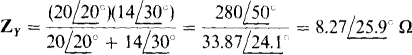
The corresponding Y impedance is 
Since the phase sequence is ACB, the line currents IA and Ic respectively lag and lead IB by 120°:

Either set of load phase currents can be found: IAB, IBC, and ICA, or IBA, IAC, and ICB. If the first set is selected, then Fig. 17-1 Id can be used, which has these currents for an ACB phase sequence. It can be seen that IAB, IBC, and ICA lag IA, IB, and Ic respectively by 30°. The magnitude of each load phase current is, of course,  Thus,
Thus,

17.20 Find the rms line voltage VL at the source of the circuit in Fig. 17-14. As shown, the rms load phase voltage is 100 V and each line impedance is 2 + j3 Ω.

Fig. 17-14
The rms line current IL can be used to find VL Of course, IL, is equal to the 100-V load phase voltage divided by the magnitude of the load phase impedance:
In flowing, this current produces a voltage drop from a source terminal to the load neutral terminal N, which drop is equal to the product of this current and the magnitude of the sum of the impedances that the current flows through. This voltage is

The line voltage at the source is equal to times this: 
17.21 Find the rms line voltage VL at the source of the circuit in Fig. 17-15. As shown, the rms line voltage at the load is 100 V and each line impedance is 2 + j3Ω.
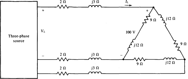
Fig. 17-15
Perhaps the best approach is to transform the A to an equivalent Y and then proceed as in the solution to Prob. 17.20. The equivalent Y impedance is (9 + j12)/3 = 3 + j4Ω. Since the line voltage at the load is 100 V, the line-to-neutral voltage for the equivalent Y load is 100/ = 57.74 V. The rms line current IL is equal to this voltage divided by the magnitude of the Y phase impedance:
In flowing, this current produces a voltage drop from a source terminal to the Y neutral terminal, which drop is equal to the product of this current and the magnitude of the sum of the impedances that the current flows through. The voltage is

And the line voltage at the source is equal to times this: 
17.22 A 480-V, three-phase, three-wire circuit has two parallel-connected balanced Δ loads, one of 5-Ω resistors and the other of 20-Ω resistors. Find the total rms line current.
Because the corresponding resistors of the Δ loads are in parallel, the resistances can be combined to produce an equivalent single A of 5||20 = 4-Ω resistors. The phase current of this Δ is equal to the line voltage divided by the 4 Ω of resistance: Ip 480/4 = 120 A. And, of course, the line current is times greater. So, IL = (120) = 208 A.
17.23 A 208-V, three-phase, three-wire circuit has two parallel-connected balanced Y loads, one of 6-Ω resistors and the other of 12-Ω resistors. Find the total rms line current.
Since the loads are balanced, the load neutral nodes are at the same potential even if there is no connection between them. Consequently, corresponding resistors are in parallel and can be combined. The result is a net resistance of 6||12 = 4Ω. This divided into the phase voltage of  gives the total rms line current: IL = 120/4 = 30 A
17.24 A 600-V three-phase circuit has two parallel-connected balanced Δ loads, one of  impedances and the other of
  impedances. Find the total rms line current and also the total average absorbed power.
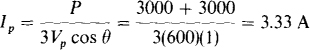
Being in parallel, corresponding Δ impedances can be combined to
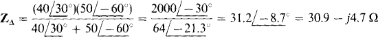
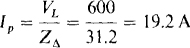
The rms phase current for the combined Δ is equal to the line voltage divided by the magnitude of this impedance:
And the rms line current is 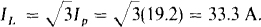
The total average power can be found using the phase current and resistance for the combined Δ:

Alternatively, it can be found from the line quantities and the power factor:

17.25 A 208-V three-phase circuit has two parallel-connected balanced loads, one a Δ of  impedances and the other a Y of
  impedances. Find the total rms line current and also the total average absorbed power.
The two loads can be combined if the Δ is transformed to a Δ or if the Y is transformed to a A so that, in effect, the loads are in parallel. If the Δ is transformed to a Y, the equivalent Y has a phase impedance of ( Since the circuit now has two balanced Y loads, corresponding impedances are in parallel and so can be combined:

The rms line current is equal to the phase voltage of  divided by the magnitude of the combined phase impedance:
Since this current effectively flows through the resistance of the combined Y, the total average power absorbed is

Alternatively, the line voltage and current power formula can be used:

17.26 A balanced Y of  impedances and a parallel-connected balanced Δ of
  impedances are connected by three wires to the secondary of a three-phase transformer. If
  V and if the phase sequence is ABC, find the total phasor line currents.
A good approach is to obtain an equivalent single combined Y impedance, and also a phase voltage, and then find a line current by dividing this phase voltage by this impedance. The other line currents can be obtained from this line current by using the phase sequence. For this approach the first step is find the equivalent Y impedance for the Δ. It is  The next step is to find a combined Y impedance ZY by using the parallel combination formula:
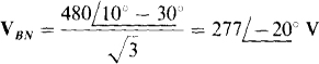
From Fig. 17-8a, which is for an ABC phase sequence, VBN has an angle that is 30° less than that of VBc and, of course, it has a magnitude that is less by a factor of 1/:
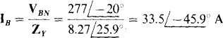
The line current IB is equal to this voltage divided by the combined Y phase impedance:
From the phase sequence, the line currents IA and Ic respectively lead and lag IB by 120°:  and
and 
17.27 A balanced Δ load of  impedances is connected by three wires, with 4 Ω of resistance each, to the secondary of a three-phase transformer. If the line voltage is 480 V at the secondary terminals, find the rms line current.
If the Δ is transformed to a Y, the Y impedances can be combined with the line resistances, and the line current found by dividing the magnitude of the total Y phase impedance into the phase voltage. The Y equivalent of the Δ has a phase impedance of
Being a Y impedance, this is in series with the line resistance and so can be combined with it. The result is

And the rms line current is equal to the phase voltage of 480/ = 277 V divided by the magnitude of this impedance: IL = 277/16.3 = 17 A
17.28 Find the average power absorbed by a balanced three-phase load in an ABC circuit in which and 
The formula  can be used if the power factor PF can be found. Since it is the cosine of the impedance angle, what is needed is the angle between a load phase voltage and current. With IB known, the most convenient phase voltage is VBA, because the desired angle is that between VBN, and IB. This approach is based on the assumption of a Y load, which is valid since any balanced load can be transformed to an equivalent Y. Figure 17-8b, which is for an ABC phase sequence, shows that VB„ leads VCB by 150°, and so here has an angle of 15° + 150° = 165°. The power factor angle, the angle between VBN and IB, is 165° — 110° = 55°. So the average power absorbed by the load is

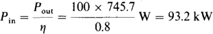
17.29 A three-phase induction motor delivers 20 hp while operating at an 85 percent efficiency and at a 0.8 lagging power factor from 480-V lines. Find the rms line current.
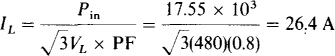
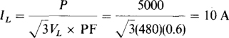
The current IL can be found from the formula  in which Pin is the input power to the motor:
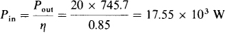
and
17.30 A three-phase induction motor delivers 100 hp while operating at an efficiency of 80 percent and a power factor of 0.75 lagging from 480-V lines. The power factor is to be improved to 0.9 lagging by inserting a Δ bank of power-factor correction capacitors. Determine the capacitance CΔ required in each phase.
The input power to the motor is

17.31 In a 208-V three-phase circuit a balanced Δ load absorbs 2 kW at a. 0.8 leading power factor. Find ZΔ.
From the phase current is
Since the line voltage is also the phase voltage, the magnitude of the phase impedance is

The impedance angle is the power factor angle: θ= —cos1 0.8 = —36.9°. So the phase impedance is 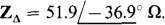
17.32 Given that 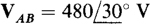 in an ABC three-phase circuit, find the phasor line currents to a balanced load that absorbs 5 kW at a 0.6 lagging power factor.
From , the line current magnitude is
If, for convenience, a Y load is assumed, then from Fig. 17-8a, VAB lags VAB by 30° and so has an angle of 30° — 30° = 0°. Since IA lags VAN by the power factor angle of θ = cos—1 0.6 = 53.1°, IA has an angle of 0° —53.1° = —53.1°. Consequently,  and, from the ABC phase sequence,


17.33 A 480-V three-phase circuit has two balanced loads connected in parallel. One is a 5-k W resistive heater and the other an induction motor that delivers 15 hp while operating at an 80 percent efficiency and a 0.9 lagging power factor. Find the total rms line current.
A good approach is to find the total complex power ST and then solve for IL from |sT| = sT = vL IL, the apparent power. Since the heater is purely resistive, its complex power is  The complex power of the motor has a magnitude (the apparent power) that is equal to the input power divided by the power factor, and it has an angle that is the arccosine of the power factor:

The total complex power is the sum of these two complex powers:

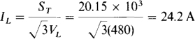
Since the apparent power is |Sr| = ST =20.15 kVA,
17.34 If in a three-phase, three-wire, ABC circuit, 
 and
and  , find the reading of a wattmeter connected with its current coil in line C and its potential coil across lines B and C. The ± terminal of the current coil is toward the source, and the ± terminal of the potential coil is at line C.
From the specified wattmeter connections, the wattmeter reading is equal to P = VL Ic cos (ang VCB — ang Ic). Of course, VL = 208 V. Also,

From an inspection of Figs. 17-8« and b, it should be fairly apparent that Vcs leads IAB by 60° and so here is  Therefore, the wattmeter reading is

17.35 A balanced Y load of 25-Ω resistors is energized from a 480-V, three-phase, three-wire, ABC source. Find the reading of a wattmeter connected with its current coil in line A and its potential coil across lines A and B. The ± terminal of the current coil is toward the source, and the ± terminal of the potential coil is at line A.
With the specified connections, the wattmeter has a reading equal to P = VL I L cos (ang VAB — ang IA), for which IL and the angles of VAB and IA are needed. Since no phasors are specified in the problem statement, the phasor VAB can be conveniently assigned a 0° angle: VAB = 480/0° V. The current IA can be found from the phase voltage VAN and the phase resistance of 25 Ω. Of course, VAN has a magnitude of 480/ = 277 v. Also, from Fig. 17-8«, it lags VAB by 30” and so has an angle of 0° - 30° = -30°. Consequently,  and
and
Since the magnitude of IA is the rms line current,

Incidentally, this wattmeter reading is just half the total average power absorbed of VLIL × PF = (480)(11.09)(1) = 9220 W. As should be evident from the two-wattmeter formulas VL IL cos (30° + 0) and VL1L cos (30° — θ), this result is generally true for a purely resistive balanced load (0 = 0°) and a wattmeter connected as if it is one of the two wattmeters of the two-wattmeter method.
17.36 A balanced Δ load of j40-Ω inductors is energized from a 208-V, ACB source. Find the reading of a wattmeter connected with its current coil in line B and its potential coil across lines B and C. The ± terminal of the current coil is toward the source, and the ± terminal of the potential coil is at line B.
With the specified connections, the wattmeter has a reading equal to P = VL IL cos (ang VBC — ang IB). for which IL and the angles of VBC and IB are needed. Since no phasors are specified, the phasor VAB can be conveniently assigned a 0° angle:  Then
Then  as is apparent from the relation between the specified ACB phase sequence and the first subscripts. It follows that

So the wattmeter reading is

This reading has, of course, no relation to the average power absorbed by the load, which must be 0 W because the load is purely inductive.
17.37 A 240-V ABC circuit has a balanced Y load of  impedances. Two wattmeters are connected for the two-wattmeter method with current coils in lines A and C. Find the wattmeter readings. Also, find these readings for an ACB phase sequence.
Since the line voltage magnitude and the impedance angle are known, only the line current magnitude is needed to determine the wattmeter readings. This current magnitude is
For the ABC phase sequence, the wattmeter with its current coil in line A has a reading of

because A precedes B in the phase sequence and there is no current coil in line B. The other wattmeter reading is

Notice that one wattmeter reading is 0 W and the other is the total average power absorbed by the load, as is generally true for the two-wattmeter method for a balanced load with a power factor of 0.5.
For the ACB phase sequence, the wattmeter readings switch because C is before B in the phase sequence and there is no current coil in line B. So, Pc = 1440 W and PA = 0 W.
17.38 A 208-V circuit has a balanced Δ load of  impedances. Two wattmeters are connected for the two-wattmeter method with current coils in lines A and B. Find the wattmeter readings for an ABC phase sequence.
The rms line current is needed for the wattmeter formulas. This current is times the rms phase current:
Since there is no current coil in line C, and since B precedes C in the phase sequence, the reading of the wattmeter with its current coil in line B is

The other wattmeter reading is

17.39 A balanced Y load is connected to a 480-V three-phase source. The two-wattmeter method is used to measure the average power absorbed by the load. If the wattmeter readings are 5 kW and 3 kW, find the impedance of each arm of the load.
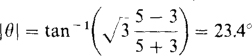
Since the phase sequence and wattmeter connections are not given, only the magnitude of the impedance angle can be found from the wattmeter readings. From the angle-power formulas, this angle magnitude is
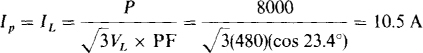
The magnitude of the phase impedance ZY can be found from the ratio of the phase voltage and current. The phase voltage is 480/ = 277 V. The phase current, which is also the line current, can be found from the total power absorbed, which is 5 + 3 = 8 kW:
From the ratio of the phase voltage and current, the magnitude of the phase impedance is 277/10.5 = 26.4 Ω. So the phase impedance is either 
17.40 Two wattmeters both have readings of 3 kW when connected for the two-wattmeter method with current coils in lines A and B of a 600-V, ABC circuit having a balanced Δ load. Find the Δ phase impedance.
For an ABC phase sequence and current coils in lines A and B, the phase impedance angle is given by
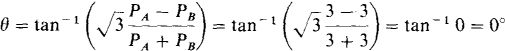
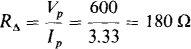
Because the load impedance angle is 0°, the load is purely resistive. The phase resistance is equal to the phase voltage of 600 V, which is also the line voltage, divided by the phase current. From P = 3 V plp cos 0,
17.41 Two wattmeters are connected for the two-wattmeter method with current coils in lines B and C of a 480-V, ACB circuit that has a balanced A load. If the wattmeter readings are 4 kW and 2 kW, respectively, find the Δ phase impedance ZΔ.
The phase impedance angle is

The magnitude of the phase impedance can be found by dividing the phase voltage of 480 V, which is also the line voltage, by the phase current. From P = 3 VpIp cos θ, the phase current is
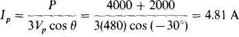
This divided into the phase voltage is the magnitude of the phase impedance. Consequently,
17.42 Two wattmeters are connected for the two-wattmeter method with current coils in lines A and C of a 240-V, ACB circuit that has a balanced Y load. Find the Y phase impedance if the two wattmeter readings are — 1 kW and 2 kW, respectively.
The impedance angle is

The magnitude of the phase impedance can be found by dividing the phase voltage of  by the phase current, which is also the line current. From
  the line current is
17.43 A 240-V, ABC circuit has an unbalanced A load consisting of resistors RAC = 45 Ω, RBA = 30 Ω, and RCB = 40 Ω. Two wattmeters are connected for the two-wattmeter method with current coils in lines A and B. What are the wattmeter readings and the total average power absorbed?
From the wattmeter connections, the wattmeter readings are equal to

For the calculations of these powers, the phasors VAC, VBC, lA, and IB are needed. Since no angles are specified, the angle of VAC can be conveniently selected as 0°, making For an ABC phase sequence, VCB leads VAC by 120° and so is  is needed:

Also, IBA lags VAC by 120° and is  The line currents IA and IB can be determined from the phase currents:
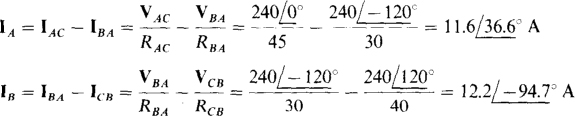
Now PA and PB can be determined:

Notice that the two wattmeter readings are not the same, even though the load is purely resistive. The reason they are not the same is that the load is not balanced.
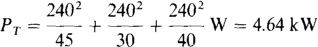
The total power absorbed is PA + PB = 2.24 + 2.4 = 4.64 kW. This can be checked by summing the V2/R power absorptions by the individual resistors:
17.44 For a four-wire, ACB circuit in which  , find the four phasor line currents to a Y load of
  and
and 
The three phase currents, which are also three of the line currents, are equal to the phase voltages divided by the phase impedances. One phase voltage is the specified VAN. The others are VBN and VCN.
From the specified ACB phase sequence, the voltages IBN and VCN respectively lead and lag IAN by 120°:  and
and 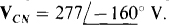 So the phase currents are
By KCL the neutral line current is

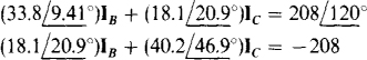
17.45 For an ABC circuit in which find the phasor line currents to a Δ load of 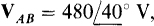 and
and 
Each line current is the difference of two phase currents, and each phase current is the ratio of a phase voltage and impedance. One phase voltage is the given IAB = 480/40° V. And from the given ABC phase sequence, the other phase voltages, 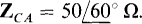 respectively lag and lead IAB by 120°:
 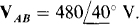 and
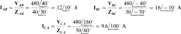
and 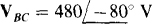 So the phase currents are
And, by KCL, the line currents are
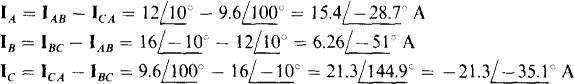
As a check, the three line currents can be added to see if the sum is zero, as it should be by KCL. This sum is zero, but it takes more than three significant digits to show this convincingly.
17.46 In a three-wire, ABC circuit in which find the phasor line currents to a Y load of  and
and 
Since the Y load is unbalanced and there is no neutral wire, the load phase voltages are not known. And this means that the line currents cannot be found readily by dividing the load phase voltages by the load phase impedances, as in the solution to Prob. 17.44. A Y-to-A transformation is tempting so that the phase voltages will be known and the approach in the solution to Prob. 17.45 can be used. But usually this is considerably more effort than using loop analysis on the original circuit.
As shown in Fig. 17-16, loop analysis can be used to find two of the three line currents, here IA and Ic. Of course, after these are known, the third line current IB can be found from them by KCL. Note in Fig. 17-16 that the VCA generator is not shown. It is not needed because the shown two generators illustrated supply the correct voltage between terminals A and C. Of course, as shown, VBC lags the given IAB by 120° because the phase sequence is ABC.
The loop equations are
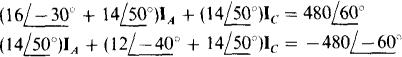
which simplify to
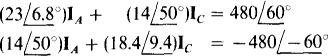
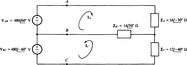
By Cramer’s rule,
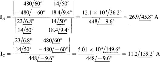
Of course, by KCL,

17.47 In the circuit of Fig. 17-16, include the third voltage generator VCA and use PSpice to obtain the three generator currents IAB, IBC, and ICA, as well as the line currents IA, IB, and Ic.
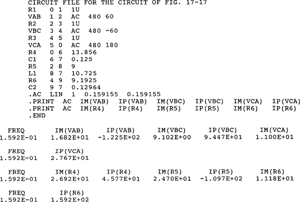
The PSpice circuit is shown in Fig. 17.17. Resistors Rl, R2, and R3 of the same negligibly small resistance have been inserted to avoid having a loop of voltage sources, which PSpice will not accept. There is nothing especially significant about the node numbering or the particular choice of the 0 node. Since
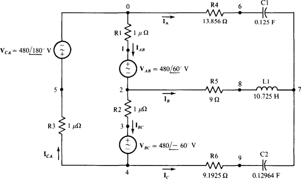
Fig. 17-17
inductances and capacitances must be specified instead of impedances, the load impedances have been converted to time-domain quantities, with the inductor and capacitor values based on a radian frequency of 1 rad/s. Then since 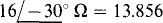 the ZA impedance is obtained with a resistor of 13.856 n in series with a capacitor of
 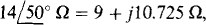 . Similarly, because
  the ZB impedance is obtained with a 9-Ü. resistor in series with a 10.725-H inductor. And since = 9.1925 – j7.7135 Ω the Zc impedance is obtained with a 9.1925-Í2 resistor in series with a capacitor of 1/7.7135 = 0.12964 F capacitance.
Following is the corresponding PSpice circuit file and the output obtained when PSpice is run with this circuit file. This output, expressed in terms of the currents specified in the circuit of Fig. 17.17 are

and

The line current values agree within three significant digits with those obtained in the solution to Prob. 17.46.
17.48 In the circuit shown in Fig. 17-18, in which each line has an impedance of 5 j8 Ω, determine IA and IB.
The loop equations are

In matrix form, these simplify to
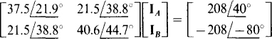
The solutions are 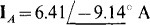 and
and  Of course
  .
.
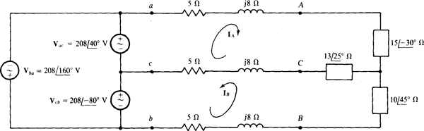
Notice in Fig. 17-18 the use of lowercase letters at the source terminals to distinguish them from the load terminals, as is necessary because of the line impedances.
17.49 In a three-wire, ACB circuit in which one phase voltage at the Y-connected source is  determine the phasor line currents to a Δ load in which
  and
and  Each line has an impedance of 4 + j7 Ω.
A good approach is to transform the Δ to a Y and then use loop analysis. The three A-to-Y transformation formulas have the same denominator of

With this inserted, the transformation formulas are
With the equivalent Y inserted for the A, the circuit is as shown in. Fig. 17-19. Because of the ACB phase sequence, VbM leads Van by 120° and Vcn lags Vam by 120°, as shown.
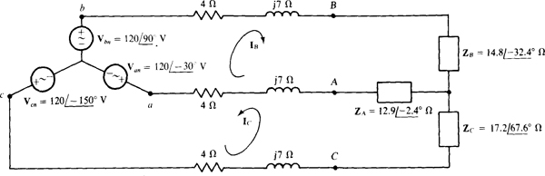
Fig. 17-19

These simplify to
The solutions are  and
and  Of course IA = — IB — Ic, from which
17.50 What is the phase sequence of a Y-connected three-phase alternator for which  and
and  Also, what is VCN?
Ans. ABC, 
17.51 Find the phase sequence of a balanced three-phase circuit in which  and
and  . Also, find VBN.
Ans. ABC, 
17.52 For a three-phase, three-wire circuit, find the phasor line currents to a balanced Y load in which each phase impedance is and for which
  . The phase sequence is,4CB.
Ans. 
17.53 Find the phase sequence of a three-phase circuit in which  and
and  Also, find the third line voltage.
Ans. ACB, 
17.54 What is the phase sequence of a three-phase circuit for which  and
and 
Ans. ACB
17.55 A balanced Y load has one phase voltage of  If the phase sequences is ABC, find the line voltages VAC, VCB, and VBA.
Ans. 
17.56 What are the phase voltages for a balanced three-phase Y load if  The phase sequence is ACB.
Ans. 
17.57 A balanced three-wire, ACB circuit has one line current of  Find the other line currents.
Ans. 
17.58 Find the Ic line current in an unbalanced three-wire, three-phase circuit in which  and
and 
Ans. 
17.59 A balanced Y load of 100-Ω resistors is connected to a 208-V, three-phase, three-wire source. Find the rms line current.
Ans. 1.2 A
17.60 A balanced Y load of  impedances is connected to a 600-V, three-phase, three-wire source. Find the rms line current.
Ans. 8.66 A
17.61 Find the phasor line currents to a balanced Y load of  impedances. One phase voltage is
  the phase sequence is ACB, and there are only three wires.
Ans. 
17.62 For a three-phase, three-wire circuit, find the phasor line currents to a balanced three-phase Y load of  impedances if
  and the phase sequence is ACB.
Ans. 
17.63 Find the phase sequence of a three-phase circuit in which two of the phase currents of a balanced A load are and  Also, find the third phase current.
Ans. ABC, 
17.64 Find the phase currents IAC, ICB, and IBA of a balanced three-phase Δ load to which one line current is  The phase sequence is ACB.
Ans. 
17.65 A balanced three-phase A load has one phase current of  . If the phase sequence is ABC, find the phasor line currents and the other phasor phase currents.
Ans. 
17.66 Find the phasor line currents to a balanced three-phase Δ load in which one phase current is  The phase sequence is ACB.
Ans. 
17.67 Find the rms value of the line currents to a balanced Δ load of 100-Ω resistors from a 480-V, three-phase, three-wire source.
Ans. 8.31 A
17.68 Find the phasor line currents to a balanced three-phase Δ load of  impedances if the phase sequence is ABC and if one phase voltage is
  .
.
Ans. 
17.69 A balanced Δ load of  impedances is energized from the Y-connected secondary of a three-phase transformer for which
  If the phase sequence is ABC, find the phasor line and load currents.
Ans. 
17.70 A balanced Y load with impedances of 8 +j6 Ω is connected to a three-phase source by three wires, each of which has 3 + j4 Í1 of impedance. The rms load phase voltage is 50 V. Find the rms line voltage at the source.
Ans. 129 V
17.71 A balanced Δ load with impedances of 15 — j9 Ω is connected to a three-phase source by three wires, each of which has 2 +j5Ω of impedance. The rms load phase voltage is 120 V. Find the rms line voltage at the source.
Ans. 150V
17.72 A 600-V, three-phase, three-wire circuit has two parallel-connected balanced Δ loads, one of 30-Ω resistors and the other of 60-Ω resistors. Find the total rms line current.
Ans. 52 A
17.73 A 480-V, three-phase, three-wire circuit has two parallel-connected balanced Y loads, one of 40-Ω resistors and the other of 120-Ω resistors. Find the total rms line current.
Ans. 9.24 A
17.74 A 480-V three-phase circuit has two parallel-connected balanced Δ loads, one of  impedances and the other of 70/50°-Ω impedances. Find the total rms line current and the total average power absorbed.
Ans. 16.8 A, 13.3 kW
17.75 A 600-V three-phase circuit has two parallel-connected balanced loads, one a Δ of impedances and the other a Y of  impedances. Find the total rms line current and the total average power absorbed.
Ans. 15.4 A, 15.4kW
17.76 A balanced Y load of  impedances and a parallel-connected balanced Δ load of
  impedances are connected by three wires to the secondary of a three-phase transformer.
  and the phase sequence is ACB, find the total phasor line currents.
Ans. 
17.77 A balanced Δ load of  impedances is connected to the secondary of a three-phase transformer by three wires that have 3 + j4 Ω. of impedance each. If the rms line voltage is 480 V at the secondary terminals, find the rms line current.
Ans. 11.1 A
17.78 Find the average power absorbed by a balanced three-phase load in an ACB circuit in which one line voltage is  and one line current to the load is
Ans. 1.34 kW
17.79 A three-phase induction motor delivers 100 hp while operating at an 80 percent efficiency and a 0.7 lagging power factor from 600-V lines. Find the rms line current.
Ans. 128 A
17.80 A three-phase induction motor delivers 150 hp while operating at an efficiency of 75 percent and a power factor of 0.8 lagging from 480-V lines. A Y bank of power factor correction capacitors is to be inserted to improve the overall power factor to 0.9 lagging. Determine the capacitance required per phase.
Ans. 456 μF
17.81 In a 480-V three-phase circuit, a balanced Δ load absorbs 5 kW at a 0.7 lagging power factor. Find the Δ phase impedance.
Ans. 
17.82 Given that  in an ACB three-phase circuit, find the phasor line currents to a balanced load that absorbs 10 kW at a 0.8 lagging power factor.
Ans. 
17.83 A 600-V three-phase circuit has two parallel-connected balanced loads. One is a synchronous motor that delivers 30 hp while operating at an 85 percent efficiency and a 0.7 leading power factor. The other is an induction motor that delivers 50 hp while operating at an 80 percent efficiency and a 0.85 lagging power factor. Find the total rms line current.
Ans. 70.2 A
17.84 If  and
and  in a three-wire, ACB circuit, find the reading of a wattmeter connected with its current coil in line A and its potential coil across lines A and B. The ± terminal of the current coil is toward the source, and the ± terminal of the potential coil is at line A.
Ans. 13.6 kW
17.85 A balanced Y load of 50-Ω resistors is connected to a 208-V, ACB, three-wire, three-phase source. Find the reading of a wattmeter connected with its current coil in line B and its potential coil across lines A and C. The ± terminal of the current coil is toward the source, and the ± terminal of the potential coil is at line A.
Ans. 0 W
17.86 A balanced Δ load with impedances of 9 + jl2 Q is connected to a 480-V, ABC source. Find the reading of a wattmeter connected with its current coil in line A and its potential coil across lines B and C. The ± terminal of the current coil is toward the source, and the + terminal of the potential coil is at line C.
Ans. -21.3 kW
17.87 A 600-V three-phase circuit has a balanced Y load of impedances. Find the wattmeter readings for the two-wattmeter method.
Ans. 5.2 kW, 2.6 kW
17.88 A 480-V, ACB circuit has a balanced Y load of  impedances. Two wattmeters are connected for the two-wattmeter method with current coils in lines B and C. Find the wattmeter readings.
Ans. PB = 4.17 kW, Pc = 2.6 kW
17.89 A 600-V, ACB circuit has a balanced Δ load of  impedances. Two wattmeters are connected for the two-wattmeter method with current coils in lines B and C. Find the wattmeter readings.
Ans. PB = 6.68 kW, Pc = 10.2 kW
17.90 A balanced Y load is connected to a 208-V three-phase source. The two-wattmeter method is used to measure the average power absorbed by the load. If the wattmeter readings are 8 kW and 4 kW, find the Y phase impedance.
Ans. Either
17.91 Two wattmeters both have readings of 5 kW when connected for the two-wattmeter method in a 480-V three-phase circuit that has a balanced Δ load. Find the A phase impedance.
Ans. 
17.92 Two wattmeters are connected for the two-wattmeter method with current coils in lines A and B of a 208-V, ABC circuit that has a balanced Δ load. If the wattmeter readings are 6 kW and — 3 kW, respectively, find the phase impedance.
Ans. 
17.93 Two wattmeters are connected for the two-wattmeter method with current coils in lines B and C of a 600-V, ABC circuit that has a balanced Y load. Find the Y phase impedance if the two wattmeter readings are 3 kW and 10 kW, respectively.
Ans. 
17.94 A 480-V, ACB circuit has an unbalanced Δ load consisting of resistors RAC = 60 Ω, RBA = 85 Ω, and RCB = 70 Ω. Two wattmeters are connected for the two-wattmeter method with current coils in lines A and C. What are the wattmeter readings?
Ans. PA = 4.63 kW, Pc = 5.21 kW
17.95. For a four-wire, ABC circuit in which  , find the four phasor line currents to a Y load of
  and
and 
Ans. 
17.96 For an ACB circuit in which  find the phasor line currents to a Δ load of
  and
and 
Ans. 
17.97 In a three-wire circuit, find in which  find the phasor line currents to a Y load of
  and
and 
Ans 
17.98 In a three-wire, ACB circuit in which one source line voltage is 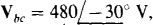 find the phasor line currents to a Y load of
  and Each line has an impedance of 3 + j 4 Ω
Ans. 
17.99 In a three-wire, ABC circuit in which one source line voltage is 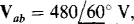 find the phasor line currents to a Δ load of
  and
and 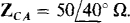 Each line has an impedance of 8 + j9Ω
Ans. 
17.100 Determine the answers that will be printed in the output file when PSpice is run with the following circuit file.
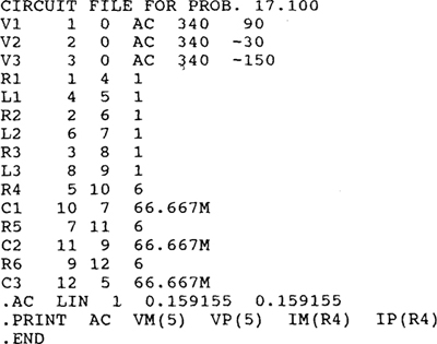
Ans.