CUSTOM DECK PROJECTS

 A Deck for Entertaining
Outdoor entertaining on a deck often involves preparing a meal. If the menu is just burgers and hot dogs, most of that food prep takes place at the grill. But even the simplest fare still involves those inevitable trips back and forth to the kitchen to toss a salad, warm up a side dish, or replenish the cold drinks. More complex meals will keep the chef in the kitchen even longer—and that means less time spent out on the deck with family and friends. Wouldn’t it be great if you could bring the kitchen to the deck to take care of more—or even all—of those food prep tasks?
At one time, outdoor kitchens were still more fantasy than reality, but that’s no longer the case. Today, Americans are increasingly seeing their decks as important outdoor entertainment areas, and not just places to park the patio table and grill. An assortment of custom grills, outdoor appliances, and storage cabinets can help you transform your deck into a fully functional kitchen. These appliances are UL-listed, so your kitchen doesn’t have to be located in a covered porch or tucked under a roof. You can cook and prepare right where you serve. Outdoor appliances are generally more expensive than their indoor cousins, but if outdoor entertaining is an important part of your lifestyle, you can now enjoy it more fully than ever before and without compromise.

Imagine the dinner parties you could host if your deck had a fully functional outdoor kitchen! It’s a trend in outdoor entertaining that continues to grow in popularity. These days, there are outdoor appliances to suit most kitchen tasks.
Whether you use your deck for intimate outdoor dining, boisterous parties, or quiet conversation, decks provide an ideal way to extend your home’s dining space into the outdoors.
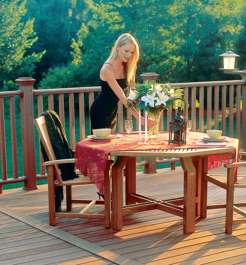
A sturdy outdoor patio table and chairs, made of suitable exterior-rated wood or metal, is a beneficial improvement to any deck. Tables that accept large shade umbrellas are even more practical, especially if your deck is located in a sunny spot.
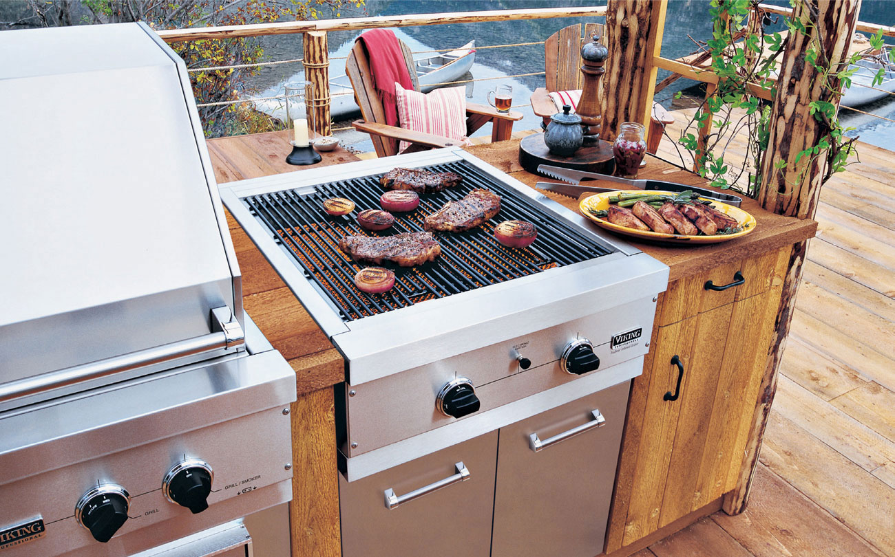
A high-end outdoor kitchen with stainless steel appliances and solid wood cabinetry leaves no question that this deck owner is serious about food.
 Outdoor Appliances
For years, better quality grills have included a sideburner and second grate to keep food warm. Now, you can purchase expansive grilling stations that may include dedicated infrared warming drawers, storage cabinets and drawers, insulated cubbies for ice, and extended serving counters. They’re a relatively affordable way to take your grilling and food preparation tasks to the next level, and you can buy these units at most home centers.
Self-contained grilling stations are just one of many appliance options to choose from. For more culinary convenience, you can also buy outdoor-rated ovens, multi-burner rangetops and refrigerators, ice makers, and beverage coolers from a number of reputable manufacturers. Ovens and rangetops are heated by either propane or natural gas, depending on the model. They’re designed as modular components that fit into a bank of cabinets or a custom-built kitchen island. Outdoor refrigerators are relatively compact and nest under a countertop where they can be at least partially sheltered from the elements. They range in capacity from around 3 to 6 cubic feet. Outdoor sinks, wet bars, and dedicated food prep stations are other options you might consider adding to your deck kitchen.

A variety of outdoor kitchen appliances, such as refrigerators, ice makers, and wine coolers, can help keep food and drinks cold no matter how hot the day may be.
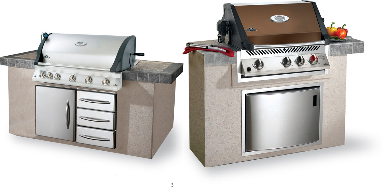
Custom barbecue islands can be configured in lots of different ways to suit your space and food prep needs. The primary appliance is generally a gas grill with a cabinet underneath for storing the LP tank. A bank of drawers provides handy places to keep grilling tools and other cooking utensils or spices.
A warming drawer outfitted in your barbecue island can help you stage various dinner items while you grill the main course. Some prefabricated barbecue islands include a warming drawer.

This self-contained beer keg cooler will keep your favorite brew cold on the hottest summer day and for as long as the party lasts. All it takes is an electrical outlet.
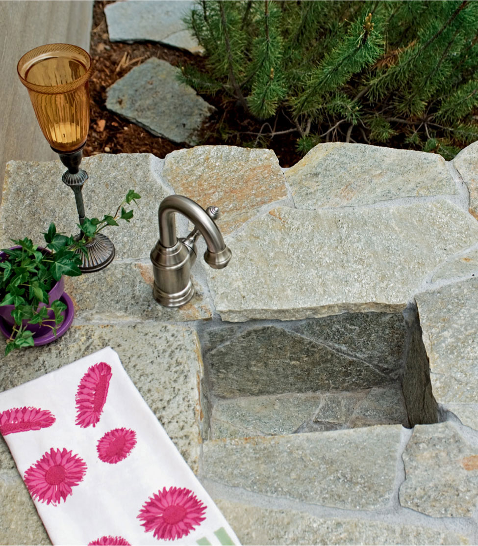
Consider adding a plumbed sink to your outdoor kitchen. It will make food prep and clean-up much easier. Be sure to check with local building codes concerning running hot and cold supply lines or installing an appropriate drain.

If your barbecue grill isn’t equipped with a side burner, it’s an essential feature you’ll want to add to your outdoor kitchen. Side burners are available as independent accessories that can be built into a kitchen island or bank of cabinets.
 Cabinets & Countertops
Once you step beyond a one-piece grilling station, you’ll need to store a stove, refrigerator, or other appliances in a system of cabinets or an island base of some kind. This could be as simple as an enclosed framework with a countertop, or it can be as elaborate as you like. Chances are, you’ll want to include a few storage cabinets and drawers to keep utensils, cookware, and other supplies close at hand. Some cabinet manufacturers offer weather-resistant cabinets made from teak, cypress, mahogany, or other exterior woods. They’re available as modular components that can be mixed and matched like other cabinetry. Polyethylene, marine-grade polymer, or stainless steel cabinets are more options to consider: they’re corrosion-resistant, waterproof, and hypoallergenic. It’s a good idea to buy your appliances first, then design an island or bank of cabinets that will fit what you own.
A variety of countertop materials could make a durable and attractive serving surface for your kitchen. Porcelain tile is weather-resistant and affordable, and it’s manufactured in virtually any style and color you can dream of. You could choose a fabricated countertop made of stainless steel, soapstone, granite, or marble. Or, build your counter from a piece of tempered glass. If your deck kitchen will be sheltered under an awning or roof, solid-surface material is also good choice. However, the polymer blends that make up solid-surface materials aren’t formulated to be UV stable, and they could deteriorate over time.
If you build your own countertop, be sure to start with a substrate layer of cement backer board if you use grouted tile or other permeable material. It will prevent water from seeping through to appliances or into storage cabinets.

If you’re a competent woodworker, consider building custom cabinets to outfit your deck kitchen rather than buying them. Make them from the same wood as your other patio furniture or decking so they blend into your deck scheme perfectly.
 Building an Island Base
For handy do-it-yourselfers, designing a weatherproof kitchen island can offer a hearty challenge and an excellent chance to explore some new building materials. Start with a framework of pressure-treated or cedar lumber, and sheathe it with waterproof cement backer board. Then, cover the exposed surfaces with patio tile, stucco, veneered stone or brick. Or, use exterior plywood as the substrate for your island framework, then follow with vinyl, fiber cement, or cedar lap siding to match the siding of your house. You could even use composite decking to sheathe your kitchen island or grilling station so it visually ties in with your deck’s design. Or, wrap the outside in sheets of stainless steel or aluminum for a sleek, modern look.
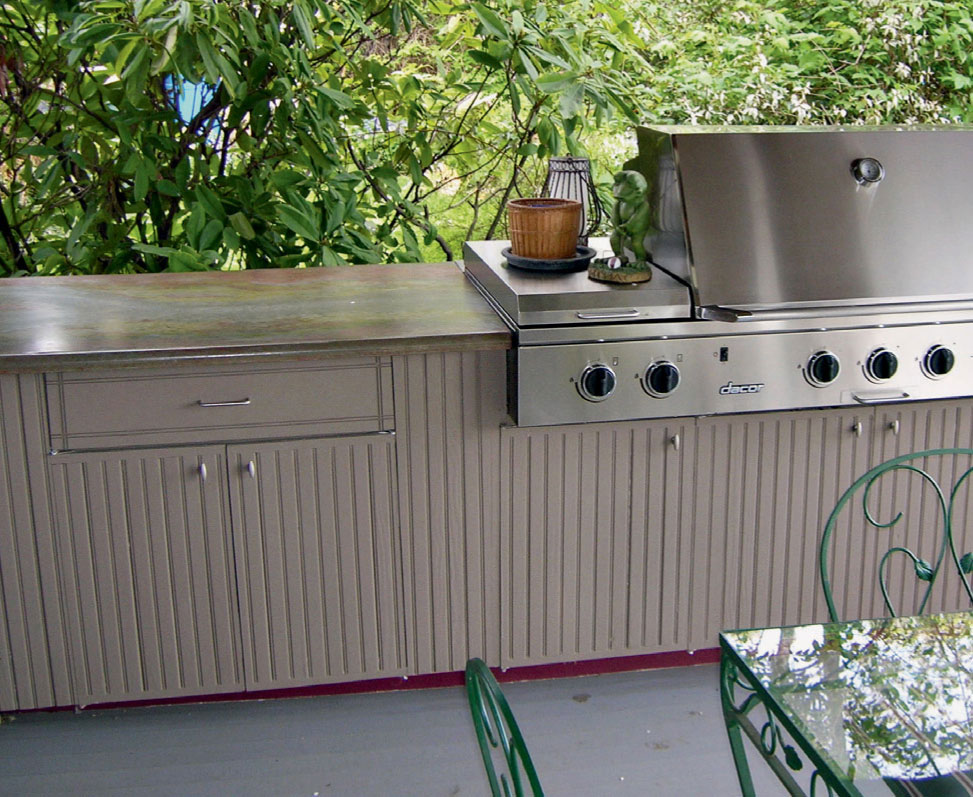
You’ll want to expand the storage capabilities of your deck kitchen by including a variety of cabinets. Exterior-grade cabinets are made with durable polymers, rot-resistant woods, or stainless steel, and they are available in a range of sizes and styles to suit your needs.
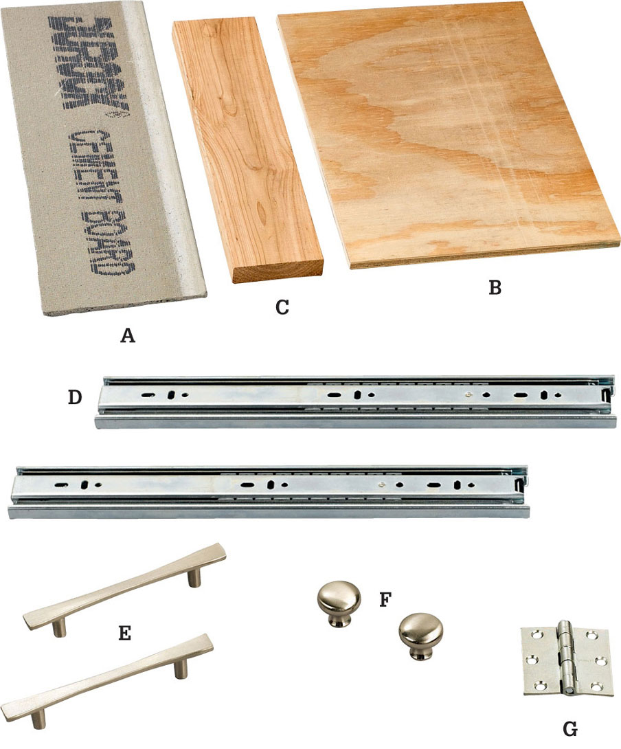
Choose water-resistant building materials for the structural and sheathing components of your island. Cement board (A), outdoor woods like cedar or redwood (B), and exterior-rated plywood (C) are all suitable home-center options. For cabinets, choose corrosion-resistant drawer slides (D), drawer hardware (E, F), and hinges (G).
Soapstone is a moderately hard, natural material that works well for exterior countertop applications. The stone is semi-porous, so it should be periodically sealed if it’s exposed to the elements. Sealing helps maintain water resistance.
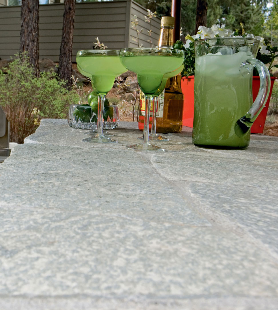
Granite is an excellent countertop material. It’s much harder than soapstone and available in many natural colors and surface textures. Common varieties of granite are in the same price range as soapstone.
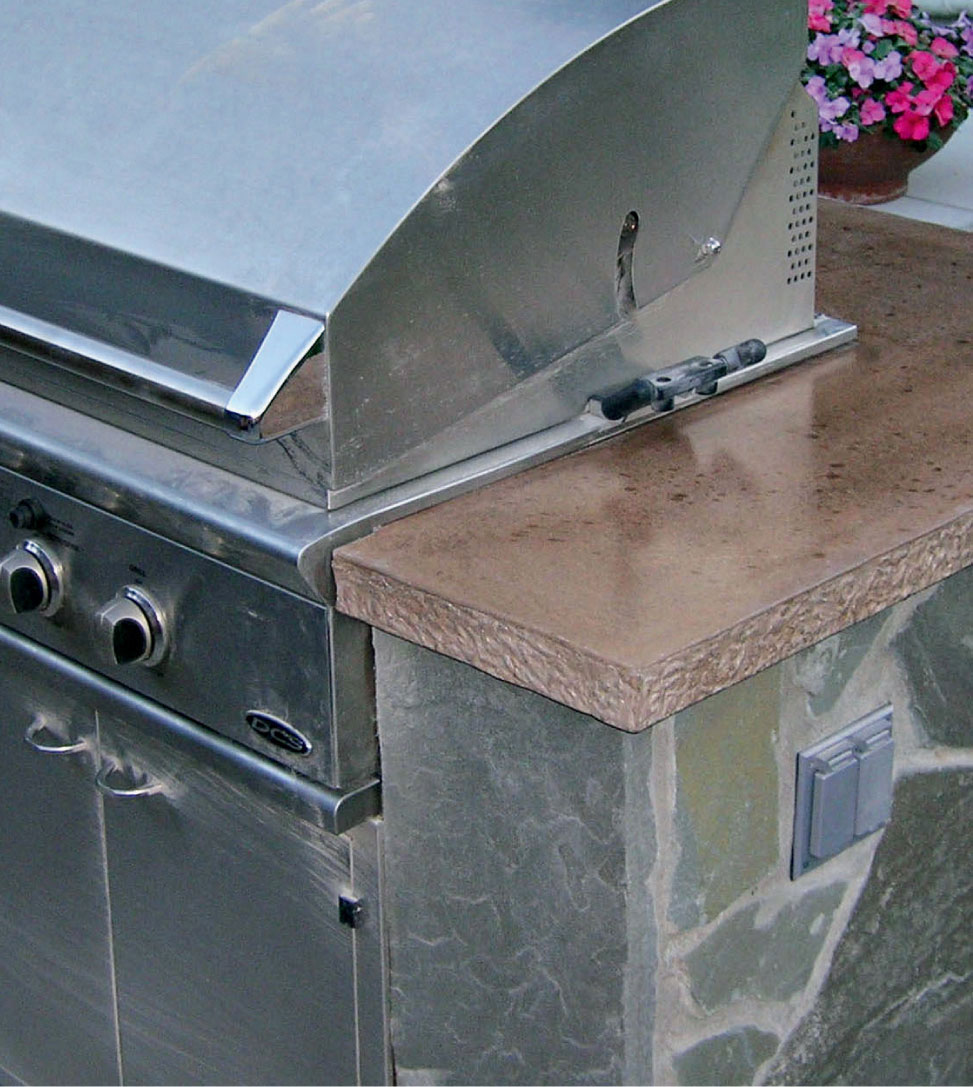
Concrete is more affordable than natural stone, and it can be tinted in a wide range of colors or mixed with other aggregates to add texture and visual interest. Another benefit to concrete is that it can be poured to suit any shape of countertop you may need.

Grouted patio tile will also work well for an outdoor kitchen countertop. It’s inexpensive, easy to install without special skills, and comes in many sizes, colors, and styles. You’ll need to seal the grout periodically if the countertop is exposed to the elements or has a sink.
 A Deck for Livability
Decks are significant investments, so you should try to use yours as much as possible. Don’t let those dog days of summer, a chilly fall afternoon, or sundown cut your deck enjoyment short. A few carefully chosen accessories can improve creature comforts and get you back out on the deck earlier each spring or extend your entertaining later into the year. If you are a serious audiophile or sports fan, an outdoor sound system or television might be just what you need to spend more time outdoors and on the deck. Manufacturers of lighting and deck accessories are continually expanding their product lines. Visit their websites or attend a home and garden show to get a better taste of what’s new and exciting in deck accessories. The selection of products on display at your local home center are just the tip of the iceberg.
The following pages cover a variety of deck accessories that will make your deck a more practical and vital part of your leisure lifestyle.
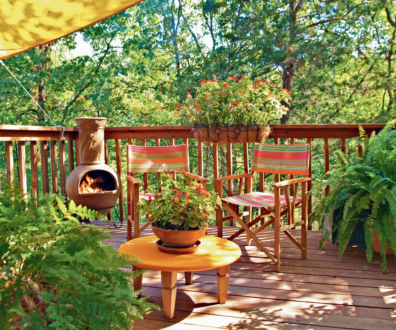
The “livability” of your deck is a somewhat intangible quality rooted in form, function, and the natural conditions that impact it. Shade and sunlight, location and furniture, amenities like hot tubs or kitchens, provisions for privacy, and the way in which the desk’s space is laid out all influence how often and well you’ll use it.
An outdoor kitchen with ample counterspace for food preparation and serving, as well as seating for casual dining, will help to make it a hard-working feature of your deck.

If your deck will receive lots of sunshine or you are located in a southern climate, consider adding a retractable sunshade for those really hot days. Or, cover a portion of your deck with a fixed awning.
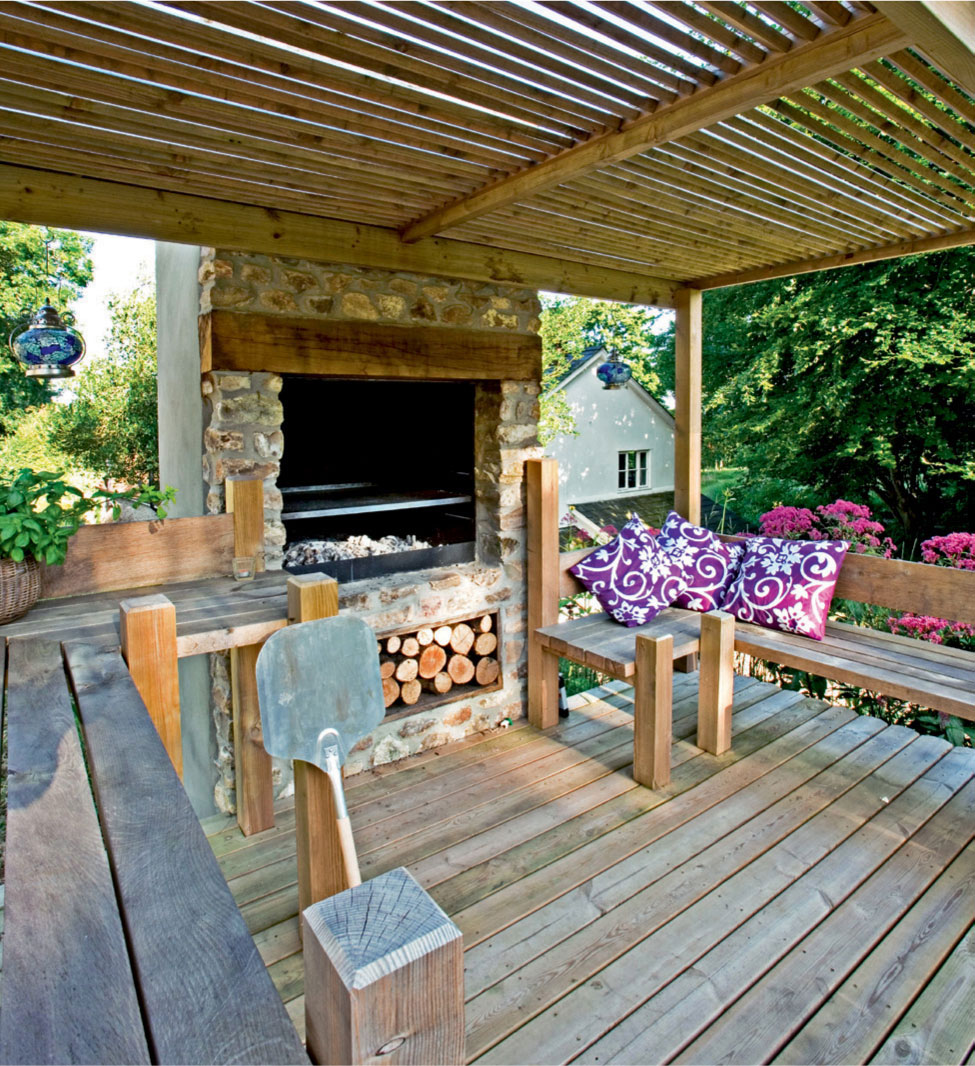
Deck living can extend well into the fall or even the winter if you include a heat source on your deck. A permanent outdoor fireplace like the one shown here is only one option. You can also buy free-standing or fixed radiant heaters that burn propane or natural gas. Or, use a chiminea or a raised firepit to keep folks warm when there’s a chill.
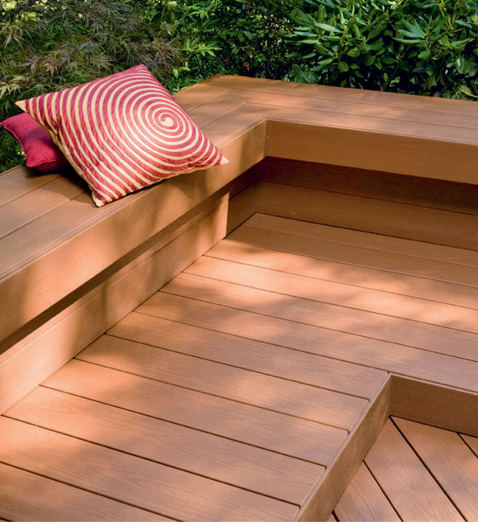
Broad, sturdy benches will invite relaxation, especially if they’re located on a portion of your deck that receives some shade. Depending on the height of your deck, fixed benches could even take the place of railings.
Recessed stair lighting clearly serves a safety function, but it also offers a cheery welcome for evening visitors. It should be combined with other light sources to create a pleasant, well-lit area.
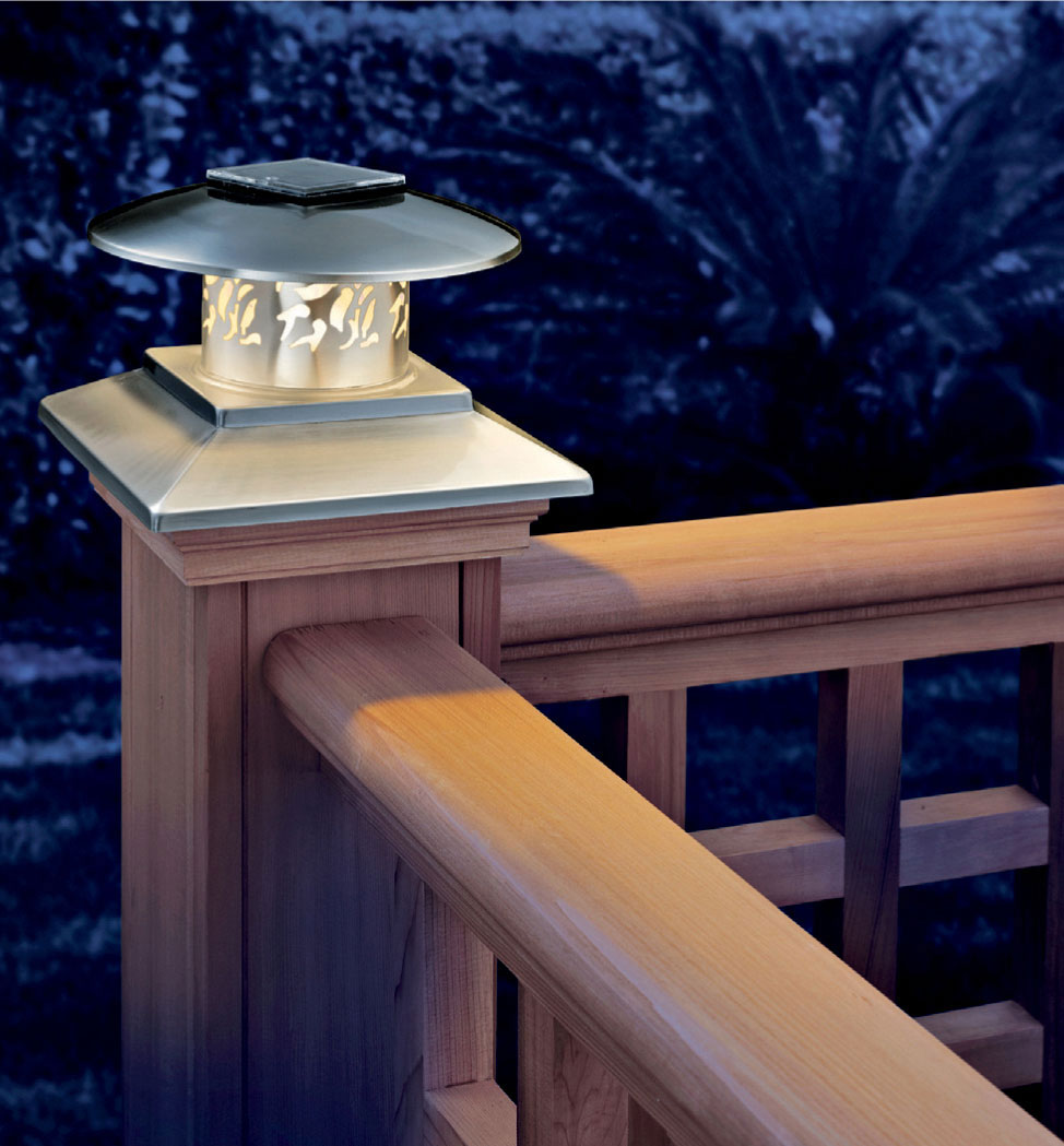
Railing posts are another good spot for adding accent lighting. You can buy low-voltage post cap lights in various styles to take your deck lighting “to the next level,” so to speak. It’s a custom touch that will impress.
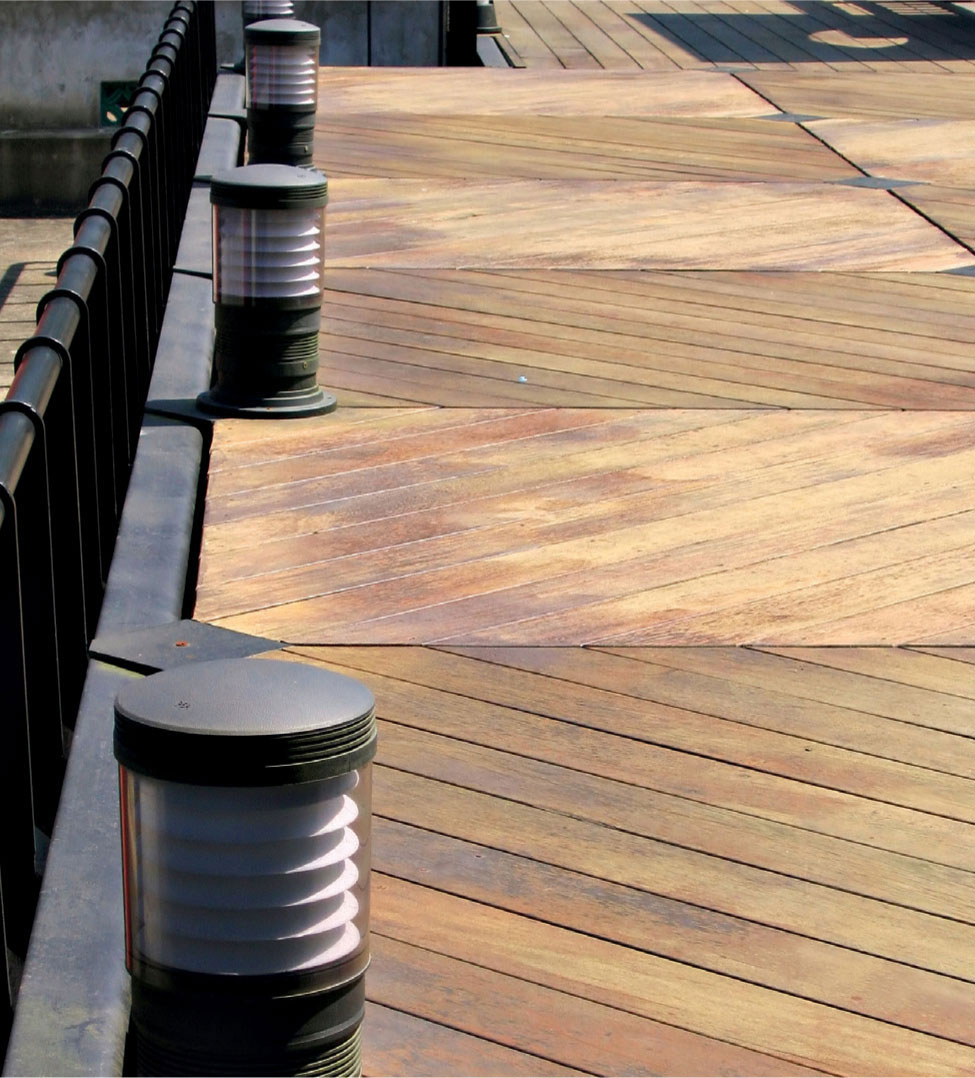
There are lots of options for deck lighting fixtures. These low-standing, pier-styled lights suggest a nautical theme and would be ideal for a deck located near a lake or other water feature.
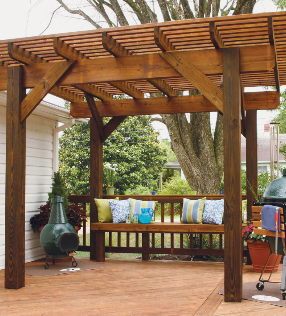
An arbor provides a pleasant filter of sun and shade. It’s also a great place to plant vining leafy plants, which will eventually cover the top and contribute even more natural shade. Wooden arbors make great DIY projects, whether you install one when your deck first goes up or any time you want to add a custom touch.
Your deck will be a more inviting place to gather and spend time if you break up the space with lots of interesting details. Raised planters, benches, and a unique railing style all contribute a sense of craftsmanship and purpose to a well-planned deck.
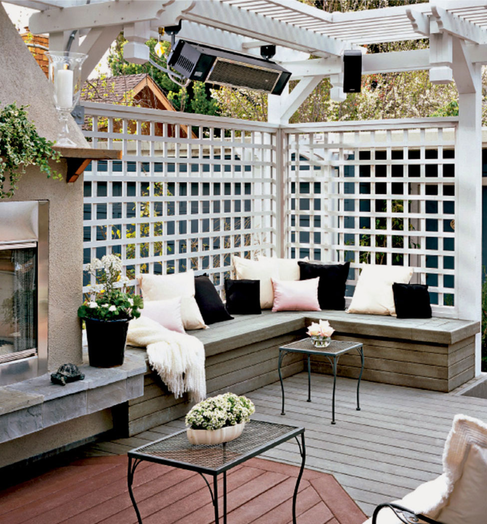
Exterior-rated audio systems and even waterproof televisions can help transform your deck into an outdoor living room. Add a few comfy patio chairs and occasional tables, and you may be surprised how much more time you spend on the deck than in the living room!
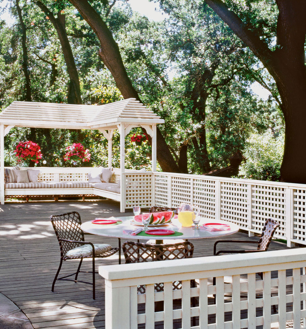
These white lattice railings and attached arbor give this deck a bright, friendly atmosphere. Thanks to ample shading, a long, cushioned bench certainly makes a perfect spot for reading or even an afternoon nap on a lazy day.
 A Deck with Power
The wiring installation shown on the following pages provides step-by-step instructions for installing light fixtures and power receptacles on a deck. These instructions are based on the National Electrical Code (NEC), which stipulates minimum standards for outdoor wiring materials. But because climate and soil conditions vary from region to region, always check with your local building and electrical codes for additional restrictions in your area. For example, some codes require that all underground cables be protected with conduit, even though the NEC allows UF cable to be buried without protection at the proper depths.
Note: This project requires general knowledge of electrical materials and techniques beyond the specific instructions shown here. Make certain you know how to do this work before attempting this project.
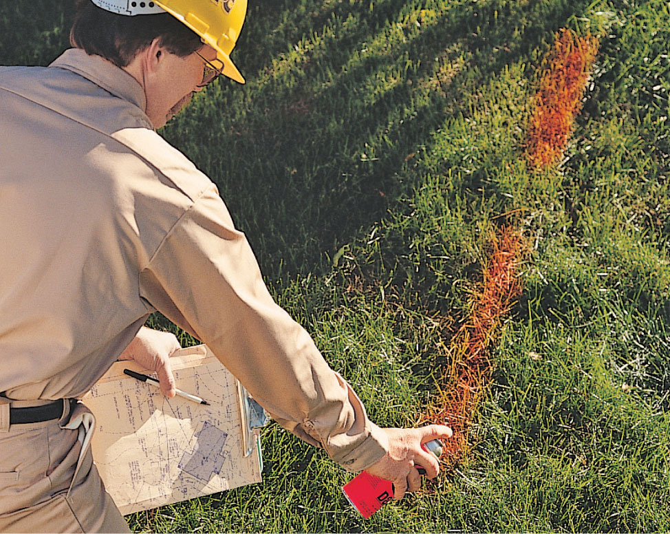
Check for underground utilities when planning trenches for underground cable runs. Avoid lawn sprinkler pipes, and call 811 or consult your electric utility office, phone company, gas and water department, and cable television vendor for the exact locations of underground utility lines. Utility companies send field representatives to accurately locate dangerous underground hazards.
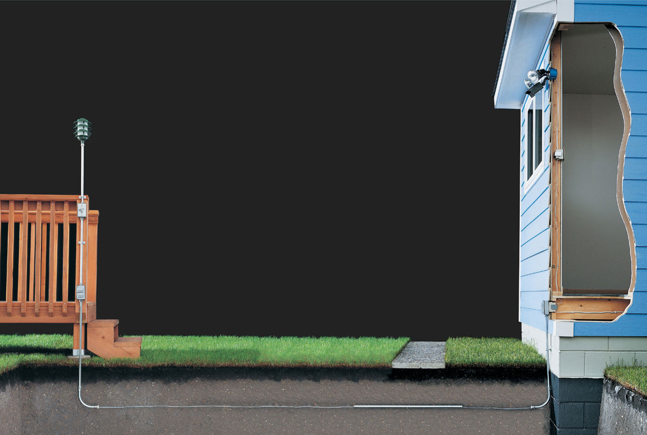
Running underground cable to supply power to your deck is a relatively simple wiring job that offers high payback in deck enjoyment for your family.
 How to Wire a Deck
Visit your electrical inspector to check local code requirements for outdoor wiring and to obtain a permit for your project. Because outdoor wiring is exposed to the elements, it requires the use of special weatherproof materials, including UF cable, rigid metal or schedule 40 PVC plastic conduit, and weatherproof electrical boxes and fittings. Some local codes allow either rigid metal or PVC plastic, while others allow only metal.
For most homes, an outdoor circuit for a deck is a modest power user. Adding a new 15-amp, 120-volt circuit provides enough power for most needs. However, if your circuit will include more than three large light fixtures (each rated for 30 watts or more) or more than four receptacles, plan to install a 20-amp, 120-volt circuit.
Consider the circuit length when choosing cable sizes for the deck circuit. In very long circuits, normal wire resistance leads to a substantial drop in voltage. If your circuit extends more than 50 feet, use cable wire that is one gauge larger to reduce the voltage drop.
For example, a 15-amp circuit that extends more than 50 feet should be wired with 12-gauge wire instead of the usual 14-gauge.
Plan to bury UF cables 12" deep if the wires are protected by a GFCI and the circuit is no larger than 20 amps. Use metal conduit or bury cable at least 24" deep if the circuit is larger than 20 amps (photo 1).
Prevent shock by making sure all outdoor receptacles are GFCI protected. A single GFCI receptacle can be wired to protect other fixtures on the circuit. Outdoor receptacles should be at least 12" above ground level and enclosed in weatherproof electrical boxes with watertight covers (photo 2).
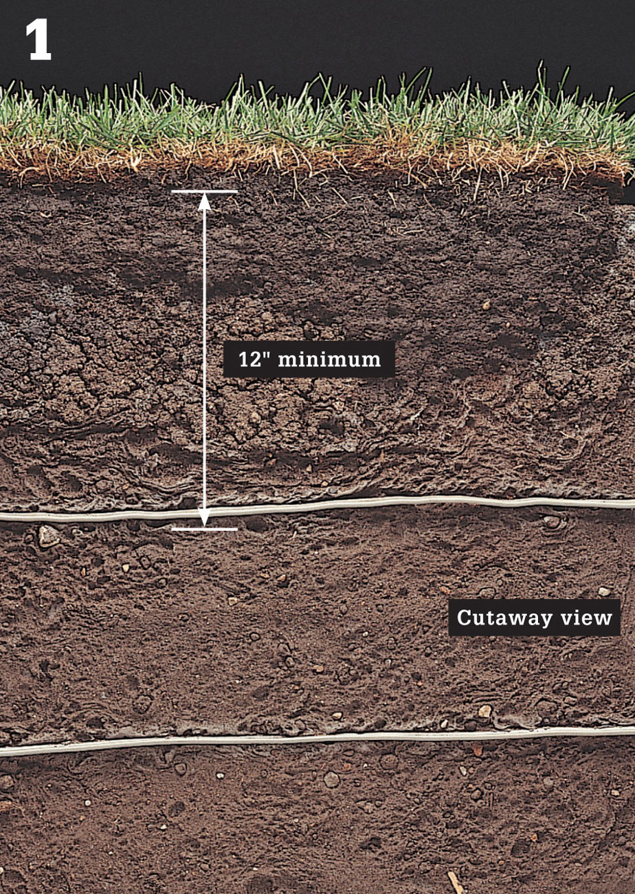
Bury UF cables 12" deep if the wires are protected by a GFCI and the circuit is no larger than 20 amps. Bury cable at least 24" deep if it is larger than 20 amps.

Install GFCI receptacles in weatherproof electrical boxes at least 1 ft.—and no more than 6-1/2 ft.—above ground level.
When laying underground cables, save time and minimize lawn damage by digging trenches as narrow as possible. Plan the circuit to reduce the length of cable runs. If your soil is sandy, or very hard and dry, water the ground thoroughly before you begin digging.
Mark the outline of the trenches with wooden stakes and string.
Cut two 18"-wide strips of plastic, and place one strip on each side of the trench outline.
Remove blocks of sod from the trench outline, using a shovel. Cut sod 2" to 3" deep to keep roots intact. Place the sod on one of the plastic strips and keep it moist but not wet. It should be replaced within two or three days, otherwise the grass underneath the plastic may die.
Dig the trenches to the depth required by your local code. Heap the dirt onto the second strip of plastic (photo 3).
To run cable under a sidewalk, cut a length of metal conduit about 12" longer than the width of sidewalk, then flatten one end of the conduit to form a sharp tip. Drive the conduit through the soil under the sidewalk using a ball-peen or masonry hammer and a wood block to prevent damage to the pipe (photo 4). Cut off the ends of the conduit with a hacksaw, leaving about 2" of exposed conduit on each side. Attach a compression fitting and plastic bushing to each end of the conduit. The plastic fittings will prevent the sharp edges of the conduit from damaging the cable sheathing.
If the trenches must be left unattended during the project, temporarily cover them with scrap plywood to prevent accidents.
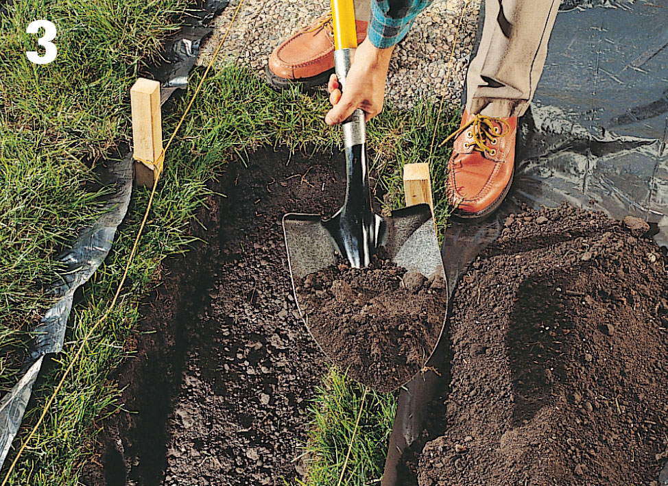
Outline trench locations with stakes and string, then dig the trenches to the depths required by your local code.
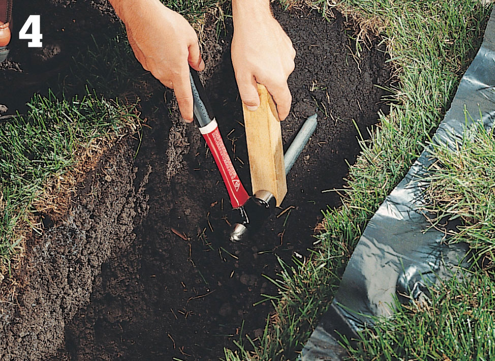
Drive conduit beneath sidewalks and other obstacles, using a block of wood and a hammer.
Outline the GFCI receptacle box on the exterior wall of the house. First drill pilot holes at the corners of the box outline, then use a piece of stiff wire to probe the wall for electrical wires or plumbing pipes. Complete the cutout with a jigsaw or reciprocating saw. Masonry variation: To make cutouts in masonry, drill a line of holes inside the box outline using a masonry bit, then remove the waste material with a masonry chisel and ball-peen hammer.
Install NM cable from the circuit breaker panel to the GFCI cutout. Allow an extra 24" of cable at the panel end and an extra 12" at the GFCI end. Attach the cable to framing members with cable staples. Strip 10" of outer sheathing from the GFCI end of the cable and 3/4" of insulation from each wire.
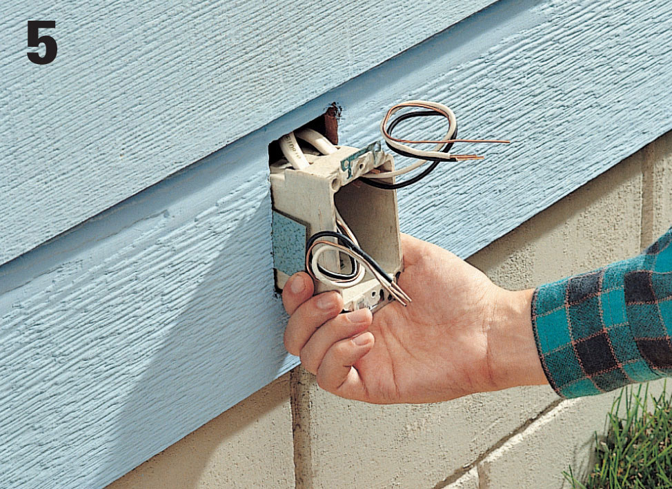
Route cables into the GFCI box, push the box into the cutout, then tighten the mounting screws until the box is secure.
Open one knockout for each cable that will enter the GFCI box. Insert the cables so at least 1/4" of sheathing reaches into the box. Push the box into the cutout and tighten the mounting screw until the bracket draws the plaster ears tight against the wall (photo 5).
Position a foam gasket over the GFCI box, then attach an extension ring to the box, using the mounting screws included with the extension ring. Seal any gaps around the extension ring with silicone caulk.
Measure and cut a length of IMC conduit (steel conduit) to reach from the bottom of the extension ring to a point about 4" from the bottom of the trench. Attach the conduit to the extension ring using a compression fitting (photo 6). Anchor the conduit to the wall with a pipe strap and masonry screws. Or use masonry anchors and pan-head screws. Drill pilot holes for the anchors using a masonry drill bit.
Attach compression fittings to the ends of the metal sweep fitting, then attach the sweep fitting to the end of the conduit. Screw a plastic bushing onto the exposed fitting end of the sweep to keep the metal edges from damaging the cable.
At the deck, attach mounting ears to the back of a weatherproof receptacle box, then attach the box to the deck frame by driving galvanized screws through the ears and into the post.
Measure and cut a length of IMC conduit to reach from the bottom of the receptacle box to a point about 4" from the bottom of the trench. Attach the conduit to the box with a compression fitting. Attach a sweep fitting and plastic bushing to the bottom of the conduit using compression fittings (photo 7).
Cut a length of IMC conduit to reach from the top of the receptacle box to the switch box location. Attach the conduit to the receptacle box with a compression fitting. Anchor the conduit to the deck frame with pipe straps.
Attach mounting ears to the back of the switch box, then loosely attach the box to the conduit with a compression fitting. Anchor the box to the deck frame by driving galvanized screws through the ears and into the wood. Tighten the compression fitting with a wrench. Measure and cut a short length of IMC conduit to reach from the top of the switch box to the deck light location. Attach the conduit with a compression fitting (photo 8).
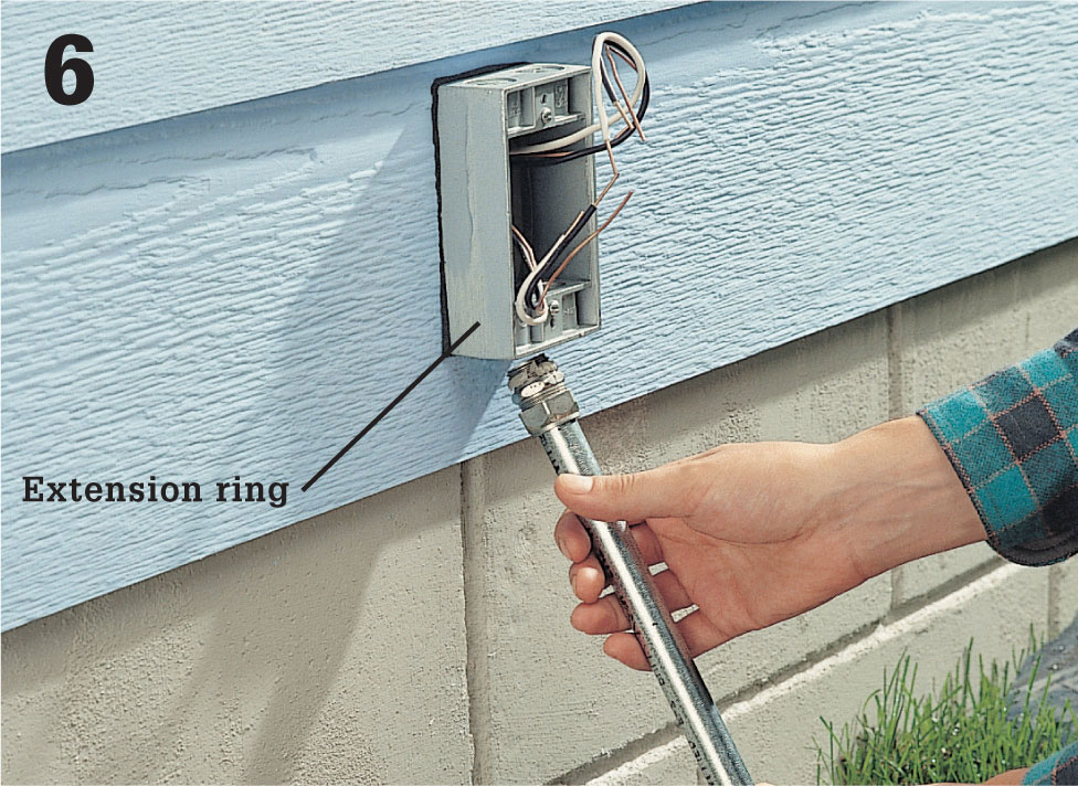
At the house, install conduit so it extends from the bottom of the extension ring to 4" from the bottom of the trench.
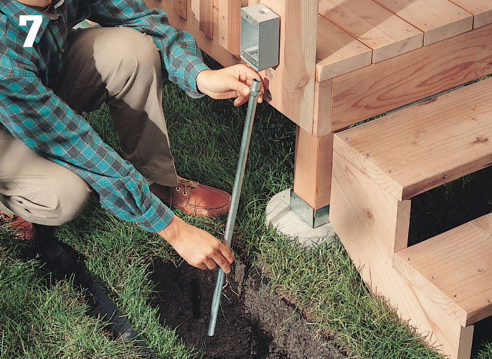
At the deck, attach conduit to the receptacle box so it extends from the bottom of the box to 4" from the bottom of the trench.
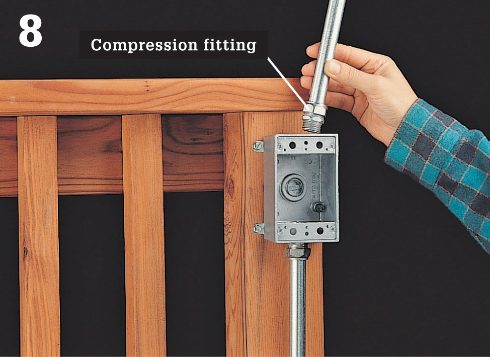
Attach conduit to the switch box so it extends from the box to the deck light location, using a compression fitting.
Measure and cut all UF cables, allowing an extra 12" at each box. At each end of the cable, use a utility knife to pare away about 3" of outer sheathing, leaving the inner wires exposed.
Feed a fish tape down through the conduit from the GFCI box. Hook the wires at one end of the cable through the loop in the fish tape, then wrap electrical tape around the wires up to the sheathing. Carefully pull the cable through the conduit (photo 9).
Lay the cable along the bottom of the trench, making sure it is not twisted. Where cable runs under a sidewalk, use the fish tape to pull it through the conduit.
Use the fish tape to pull the end of the cable up through the conduit to the deck receptacle box at the opposite end of the trench (photo 10). Remove the cable from the fish tape.
Cut away the electrical tape at each end of the cable, then clip away the bent wires. Bend back one of the wires in the cable, and grip it with needlenose pliers. Grip the cable with another pliers, then pull back on the wire, splitting the sheathing and exposing about 10" of wire. Repeat with the remaining wires, then cut off excess sheathing with a utility knife. Strip
3/4" of insulation from the end of each wire using a combination tool.
Measure, cut, and install a cable from the deck receptacle box to the outdoor switch box, using the fish tape. Strip 10" of sheathing from each end of the cable, then strip 3/4" of insulation from the end of each wire using a combination tool.
Attach a grounding pigtail to the back of each metal box and extension ring. Join all grounding wires with a wire connector. Tuck the wires inside the boxes, and temporarily attach the weatherproof coverplates until the inspector arrives for the rough-in inspection (photo 11).
At the GFCI receptacle, connect the black feed wire from the power source to the brass terminal marked “line.” Connect the white feed wire from the power source to the silver screw terminal marked “line.”
Attach the short white pigtail wire to the silver screw terminal marked “load,” and attach a short black pigtail wire to the brass screw terminal marked “load.”
Connect the black pigtail wire to all the remaining black circuit wires using a wire connector. Connect the white pigtail wire to the remaining white circuit wires.
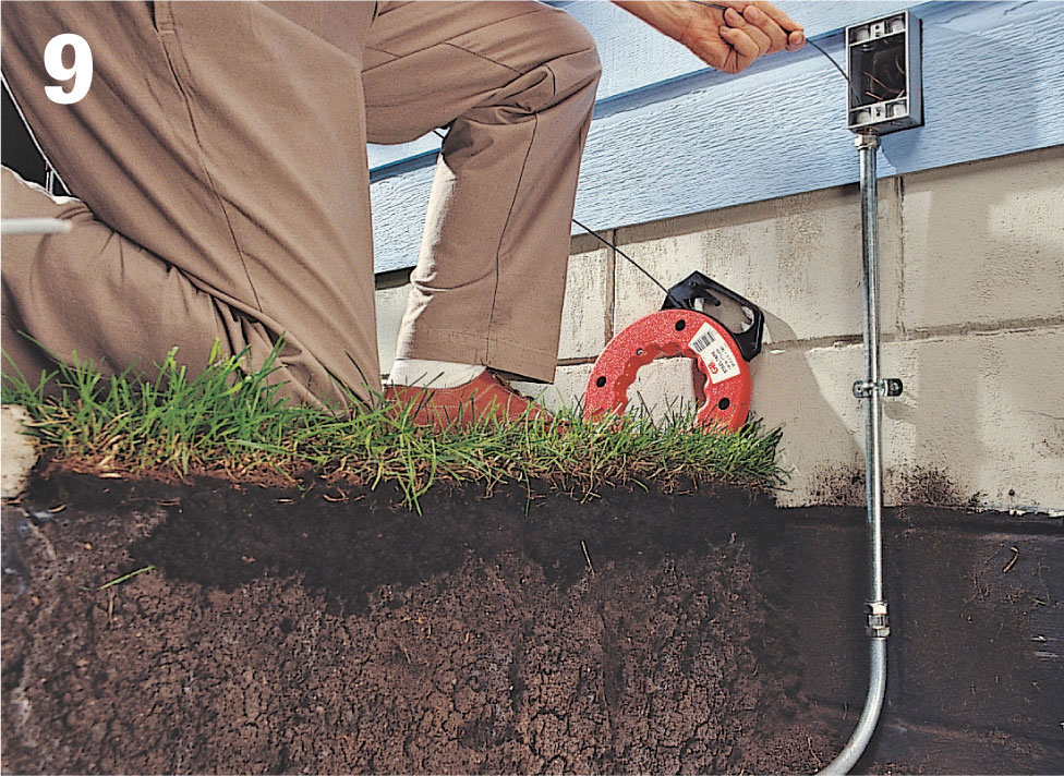
At the house, use fish tape to pull cable through the conduit and into the GFCI box.
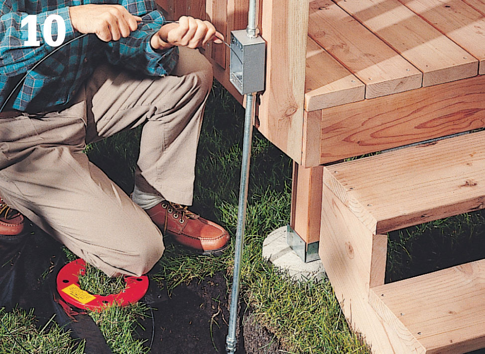
At the deck, use the fish tape to pull cable through the conduit and into the receptacle box and switch box.
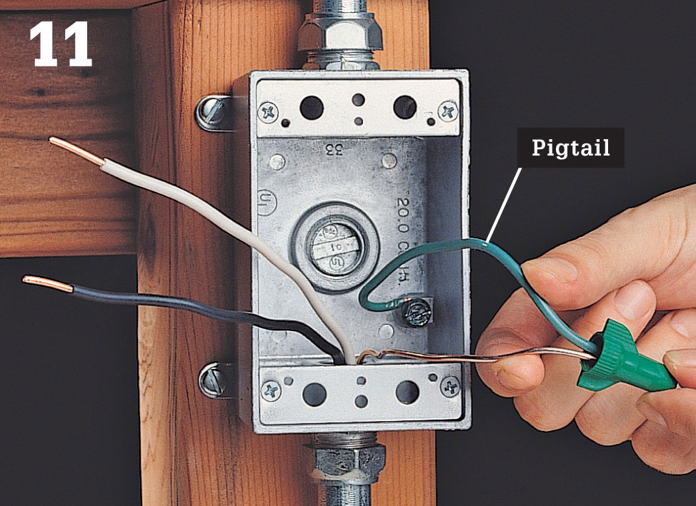
Connect a grounding pigtail to each metal box and extension ring and join all grounding wires with the pigtail. Install the coverplates for the rough-in inspection.
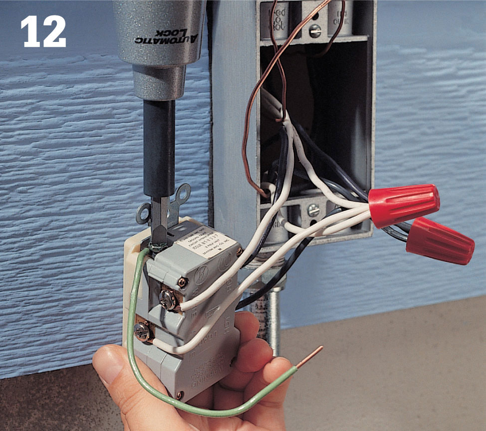
Attach a grounding pigtail to the grounding screw on the GFCI. Join the grounding pigtail to the bare copper grounding wires using a wire connector (photo 12).
Carefully tuck the wires into the box. Mount the GFCI, then fit a foam gasket over the box and attach the weatherproof coverplate.
At each remaining receptacle in your deck circuit, connect the black circuit wires to the brass screw terminals on the receptacle. Connect the white circuit wires to the silver screw terminals on the receptacle. Attach a grounding pigtail to the grounding screw on the receptacle, then join all grounding wires with a wire connector.
Carefully tuck all wires into the box, and attach the receptacle to the box using the mounting screws. Fit a foam gasket over the box, and attach the weatherproof coverplate.
Thread the wire leads of the light fixture through a threaded compression fitting. Screw the union onto the base of the light fixture (photo 13).
Feed the wire leads through the conduit and into the switch box. Slide the light fixture onto the conduit, and tighten the compression fitting.
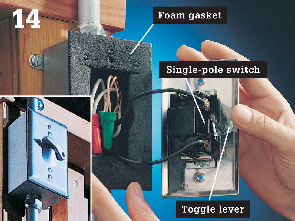
Switches for outdoor use have weatherproof coverplates with built-in toggle levers. The lever operates a single-pole switch mounted to the inside of the coverplate.
Connect the black circuit wire to one of the screw terminals on the switch, and connect the black wire lead from the light fixture to the other screw terminal.
Connect the white wire lead to the white circuit wire with a wire connector (photo 14). Use a wire connector to join the grounding wires.
To install a weatherproof switch, connect the black circuit wire to one of the screw terminals on the switch, and the black wire lead from the fixture to the other screw terminal. Use wire connectors to join the white circuit wires and the grounding wires.
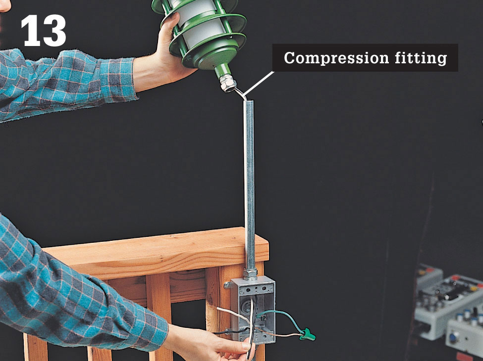
Feed the wire leads through the conduit into the switch box, then attach the light fixture using a compression fitting.
To install a GFCI receptacle, connect the black feed wire from the power source to the brass screw terminal (line), and the white feed wire to the silver screw terminal (line). Use pigtails and wire connectors to connect the remaining black circuit wires to the brass screw terminal (load), the white circuit wires to the silver screw terminal (load), and the green or copper wires to the grounding screw.
 How to Install Low-voltage Step Lights
Low-voltage recessed lights are great for decks. Installed inconspicuously in the deck boards, they provide accent lighting for plant boxes or pathway lighting for stairs.
Use the template or trace the bottom of the fixture onto the treads to mark a hole for each light. Center the fixture on the tread, 1 to 2" from the edge (the hole will center on the gap between the 2 × 6s on most deck stairs).
Drill holes at the corners, then cut the holes with a jigsaw (photo 1).
Test the fixtures to be sure they will fit (they should fit snugly), and adjust the holes as necessary.
Run cable to the stairs from an existing low-voltage system or from a new transformer. Drill a hole in the bottom riser if necessary, and snake the cable under the stairs along the inside edge.
Pull a loop of cable through each of the holes for the fixtures and temporarily secure it to the tread with tape (photo 2).
At the middle of the first loop of cable in the series, separate 3 to 4" of the two conductors in the cable by slicing down the center.
Strip about 2" of insulation off of each wire. Cut the wire in the center of the stripped section, and twist the two ends and the end of one of the fixture wires into an outdoor wire connector (photo 3). Secure the connection with electrical tape.
Repeat with the other fixture wire and the other circuit wire.
Tuck the wires back into the hole, and place the fixture into the hole.
Test each fixture before installing the next one.
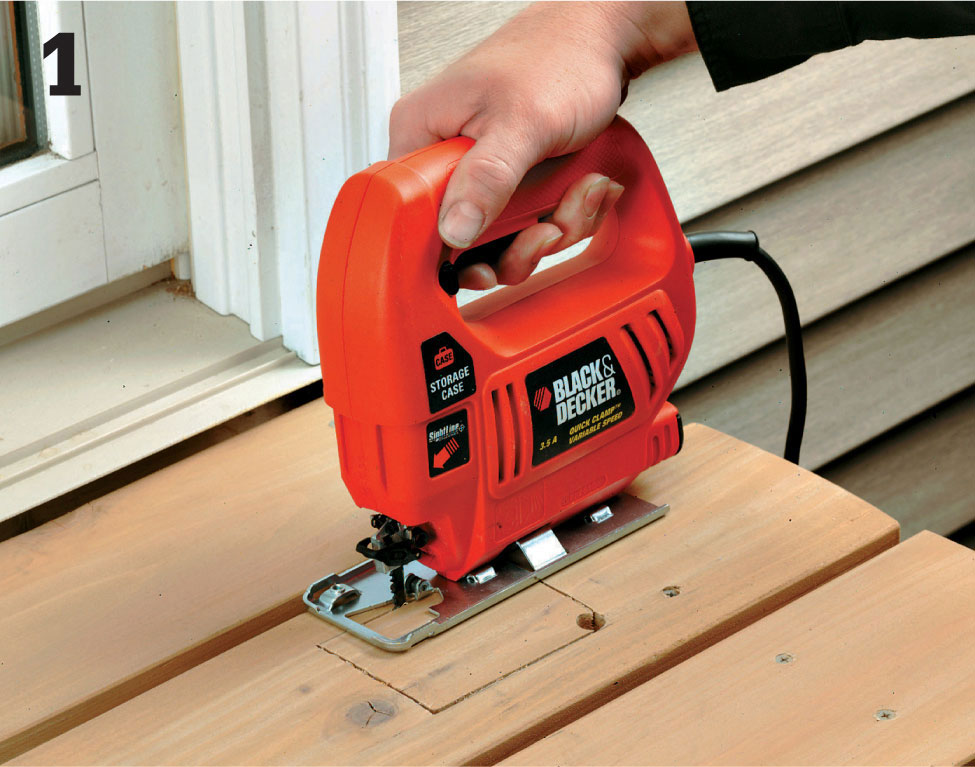
Mark the fixture location, drill pilot holes at the corner of the cutout, then cut the holes using a jigsaw.
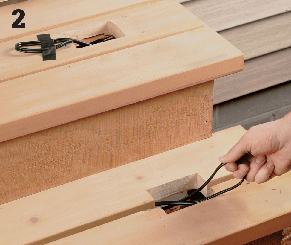
Run the cable from an existing low-voltage system or from a new transformer to the stair location.
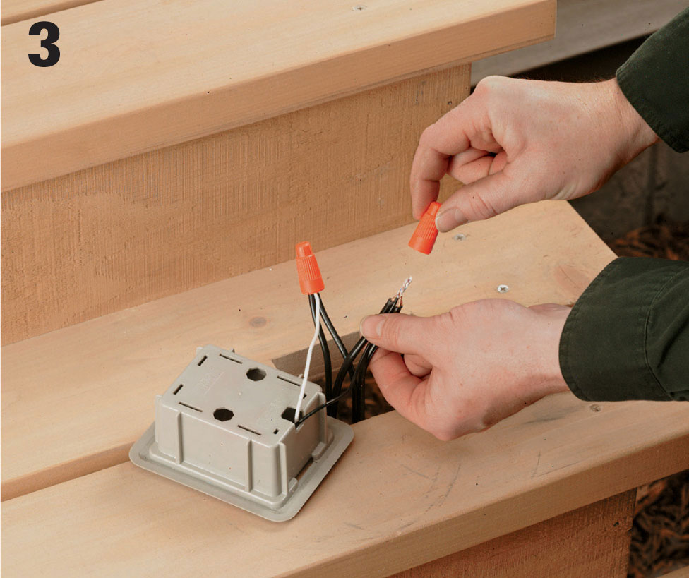
Join the lead wires of the fixture with the wires of the low-voltage cable using outdoor wire connectors.
 How to Install Low-voltage Railing Lights
Rope light is thin, flexible, clear tubing with tiny light bulbs embedded every few inches along its length. Most rope lights are meant to plug into a receptacle and use household current. While this is all right for indoor decorating, it limits their use outdoors. Low-voltage versions, however, are powered by transformers and can be connected inconspicuously to a low-voltage landscape lighting circuit. They are available from specialty lighting stores and catalogs.
Run a cable from a transformer or from a nearby low-voltage circuit using a T-connector.
Route the cable up a post at the end of the rail, and secure it with cable staples. Leave enough length at the end of the cable to connect it to the rope light (photo 1).
Secure the rope light to the underside of the railing with U-channel. Cut the channel to length, and nail it to the bottom of the railing.
Press the rope into the channel (photo 2).
Connect the fixture cord to the end of the rope with the twist-on fitting.
Connect the rope wires to the branch cable with a cable connector designed for low-voltage outdoor cable (photo 3).
Cap the end of the rope with a plastic cap.
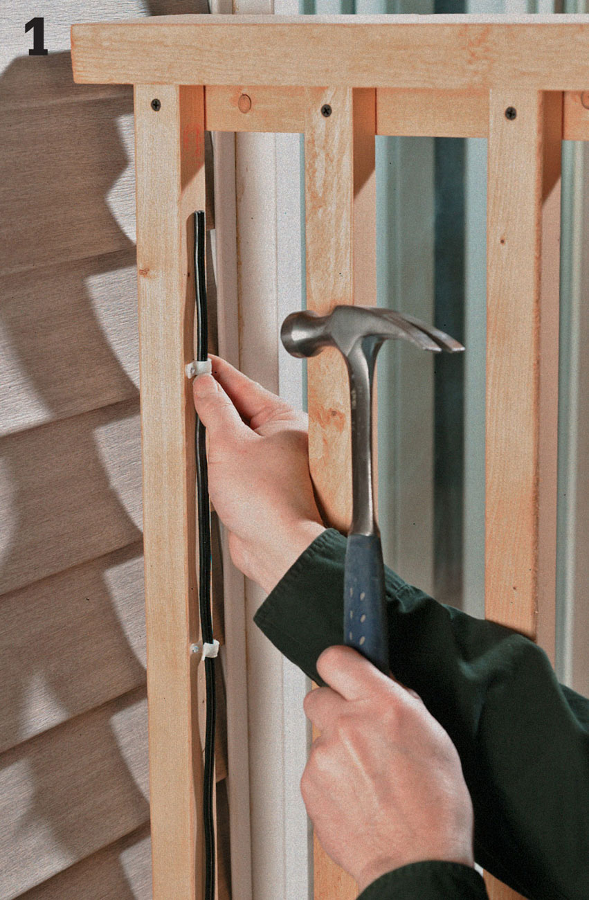
Run low-voltage cable from a transformer or low-voltage circuit to the end of the railing and secure with cable staples.
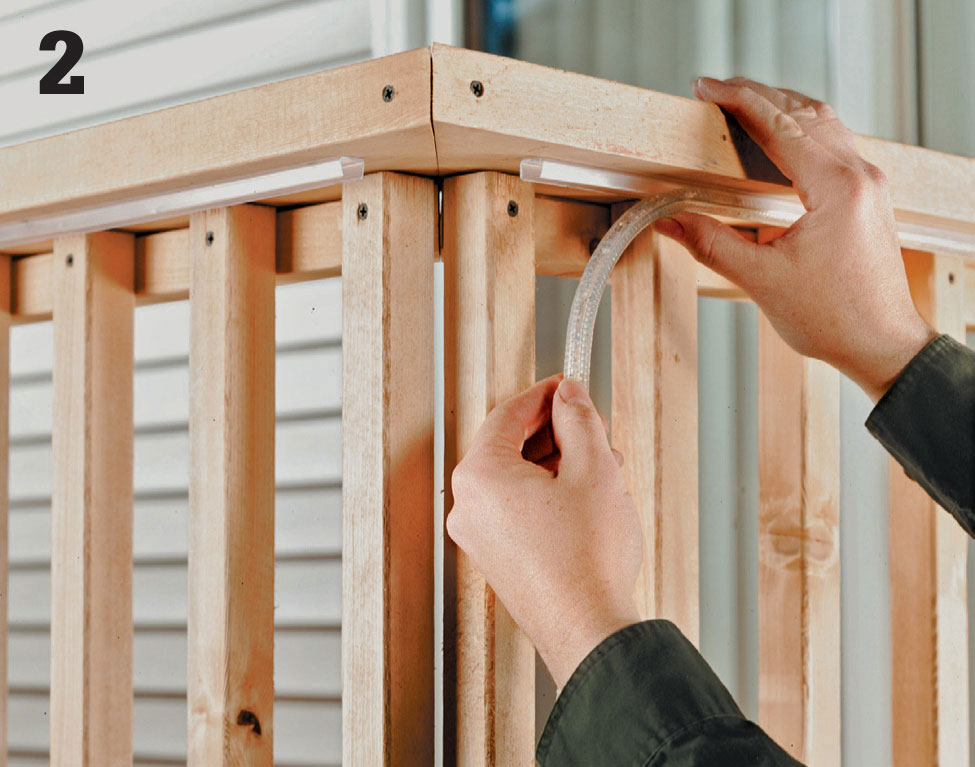
Fasten U channel to the bottom of the railing, then press the rope light in the channel securely.
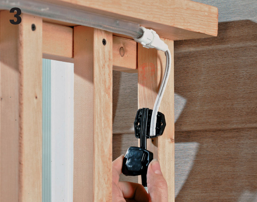
Connect the rope wires to the branch cable with a cable connector designed for outdoor cable.
 Under-deck Enclosure
Second-story walkout decks can be a mixed blessing. On top, you have an open, sun-filled perch with a commanding view of the landscape. The space below the deck, however, is all too often a dark and chilly nook that is functionally unprotected from water runoff. As a result, an under-deck area often ends up as wasted space or becomes a holding area for seasonal storage items or the less desirable outdoor furniture.
But there’s an easy way to reclaim all that convenient outdoor space—by installing a weatherizing ceiling system that captures runoff water from the deck above, leaving the area below dry enough to convert into a versatile outdoor room. You can even enclose the space to create a screened-in patio room.
The under-deck system featured in this project (see Resources) is designed for do-it-yourself installation.
Its components are made to fit almost any standard deck and come in three sizes to accommodate different deck-joist spacing (for 12", 16", and 24" on-center spacing). Once the system is in place, the under-deck area is effectively “dried in,” and you can begin adding amenities like overhead lighting, ceiling fans, and speakers to complete the outdoor room environment.
The system works by capturing water that falls through the decking above and channeling it to the outside edge of the deck. Depending on your plans, you can let the water fall from the ceiling panels along the deck’s edge, or you can install a standard rain gutter and downspout to direct the water to a single exit point on the ground or a rain barrel. Steps for adding a gutter system are given on pages 261 to 263.
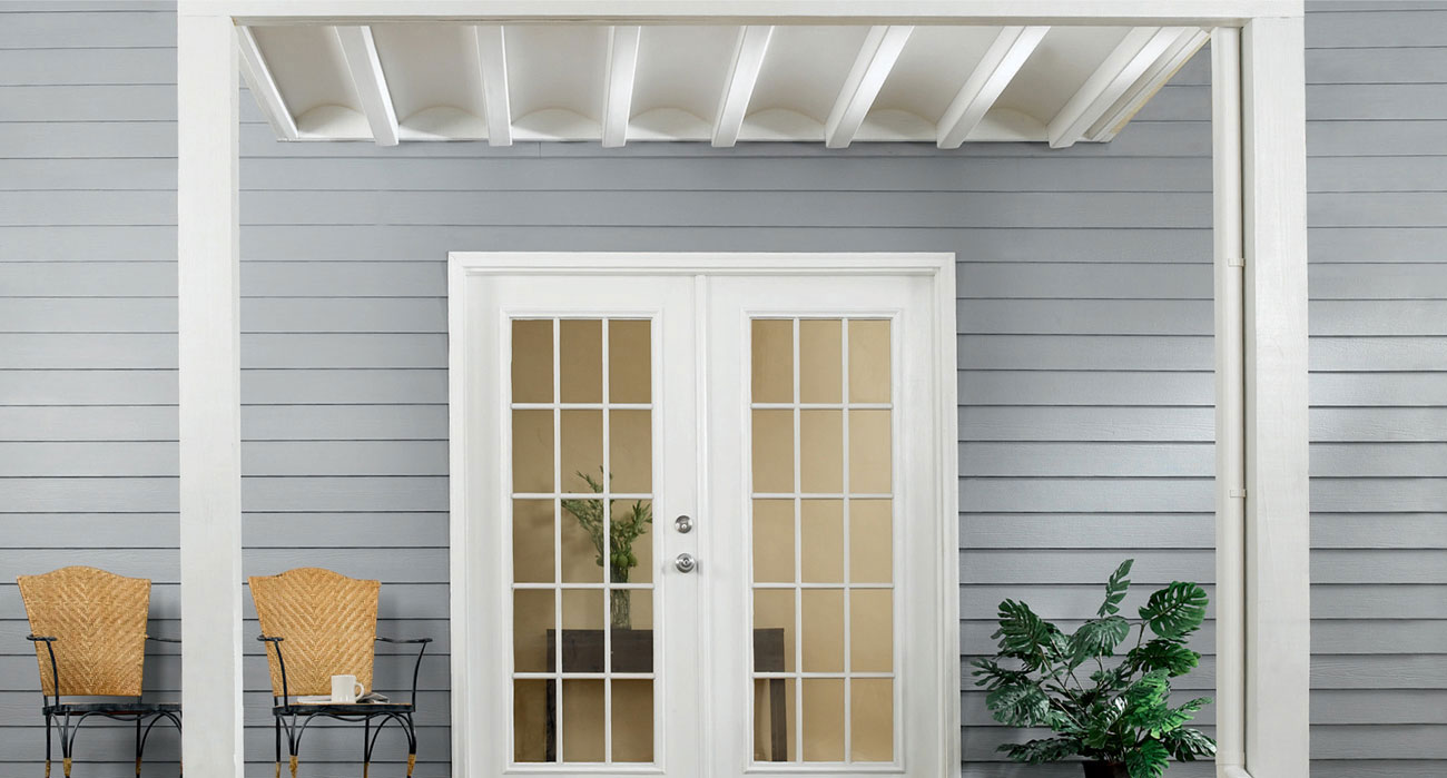
Made of weather-resistant vinyl, this under-deck system creates an attractive, maintenance-free ceiling that keeps the space below dry throughout the seasons.
 Design Tips
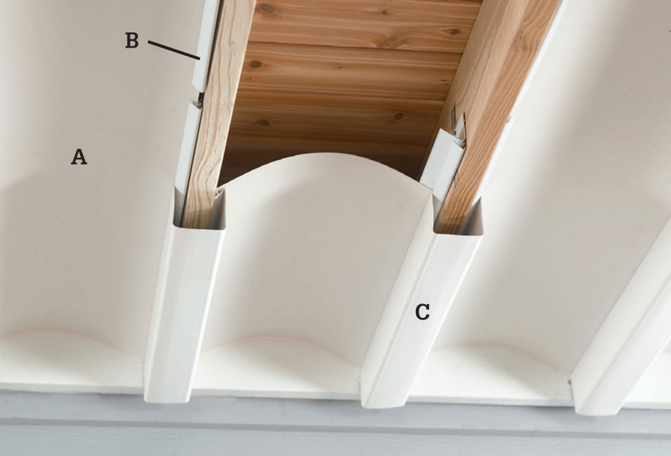
This under-deck system (see Resources, page 347) consists of four main parts: The joist rails mount to the deck joists and help secure the other components. The collector panels (A) span the joist cavity to capture water falling through the deck above. Water flows to the sides of the panels where it falls through gaps in the joist rails (B) and into the joist gutters (C) (for interior joists) and boundary gutters (for outer joists). The gutters carry the water to the outside edge of the deck.
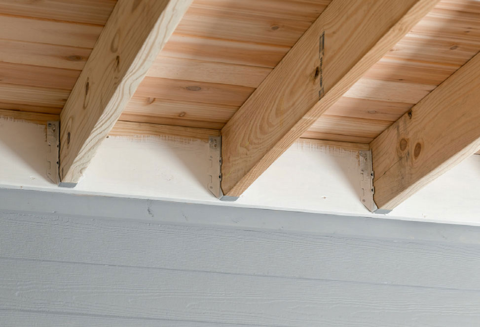
For a finished look, paint the decking lumber that will be exposed after the system is installed. Typically, the lower portion of the ledger board (attached to the house) and the outer rim joist (at the outer edge of the deck) remain exposed.
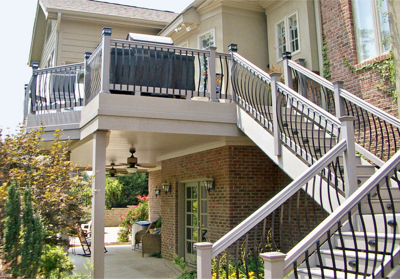
Consider surrounding architectural elements when you select a system for sealing off the area below your deck. Here, the under-deck system is integrated with the deck and deck stairs both visually and functionally.
 How to Install an Under-deck System
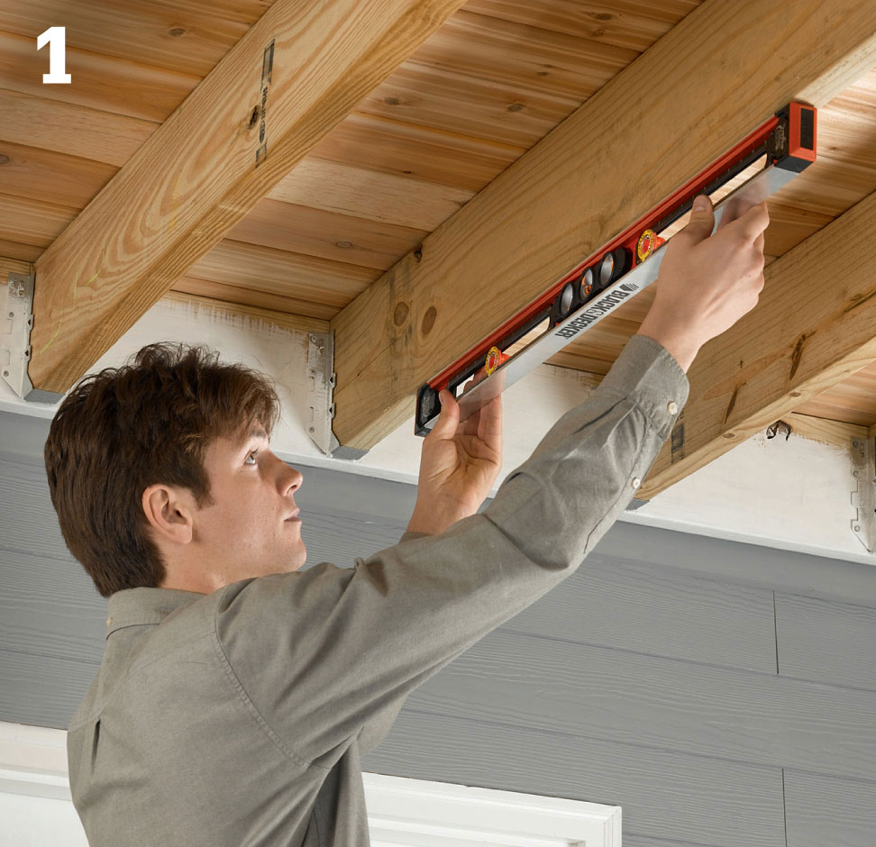
Check the undersides of several deck joists to make sure the structure is level. This is important for establishing the proper slope for effective water flow.
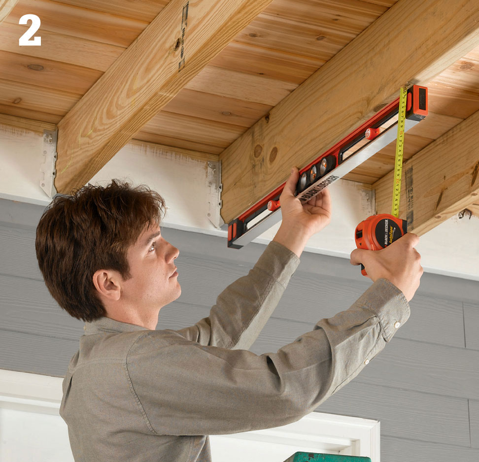
If your deck is not level, you must compensate for this when setting the ceiling slope. To determine the amount of correction that’s needed, hold one end of the level against a joist and tilt the level until it reads perfectly level. Measure the distance from the joist to the free end of the level. Then, divide this measurement by the length of the level. For example, if the distance is 1/4" and the level is 4 ft. long, the deck is out of level by 1/16" per foot.
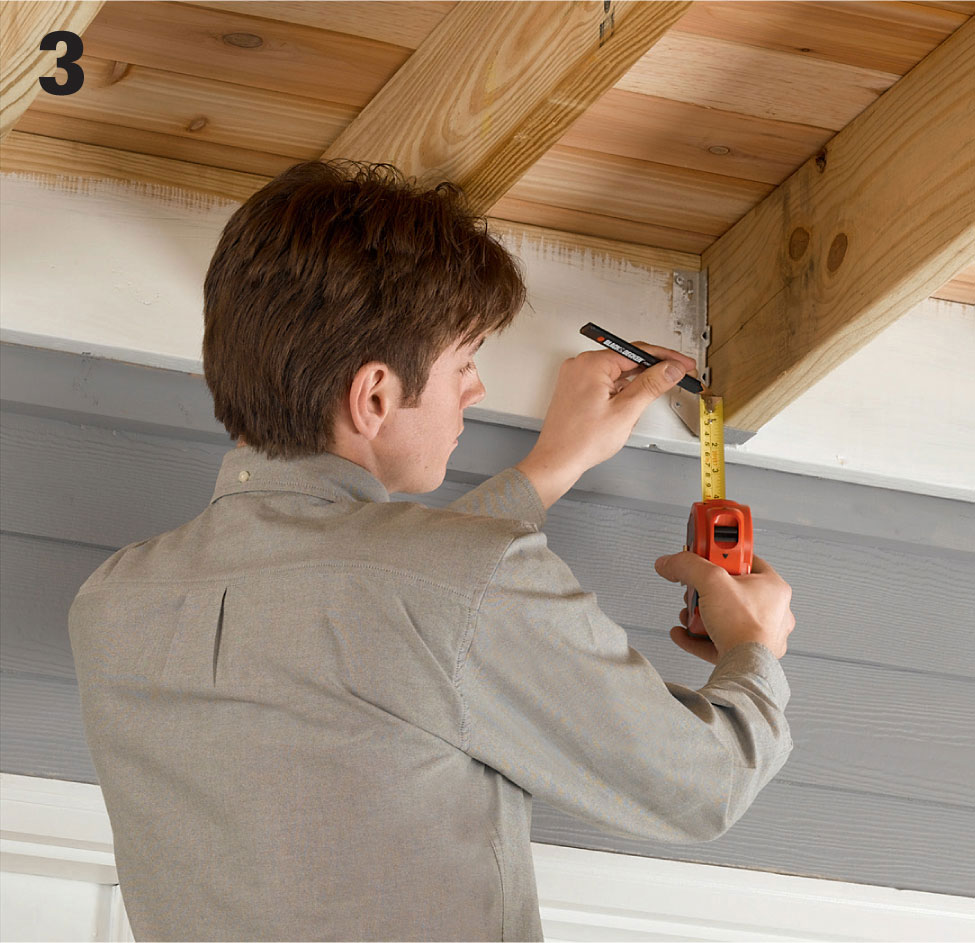
To establish the slope for the ceiling system, mark the ends of the joists closest to the house: Measure up from the bottom 1" for every 10 ft. of joist length (or approximately 1/8" per ft.) and make a mark. Mark both sides of each intermediate joist and the inside faces of the outer joists.
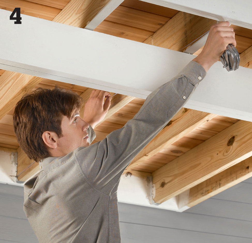
Create each slope reference line using a chalk line: Hold one end of the chalk line at the mark made in Step 3, and hold the other end at the bottom edge of the joist where it meets the rim joist at the outside edge of the deck. Snap a reference line on all of the joists.
Install vinyl flashing along the ledger board in the joist cavities. Attach the flashing with 1" stainless steel screws. Caulk along the top edges of the flashing where it meets the ledger and both joists, using quality, waterproof acrylic caulk. Also caulk the underside of the flashing for an extra layer of protection.
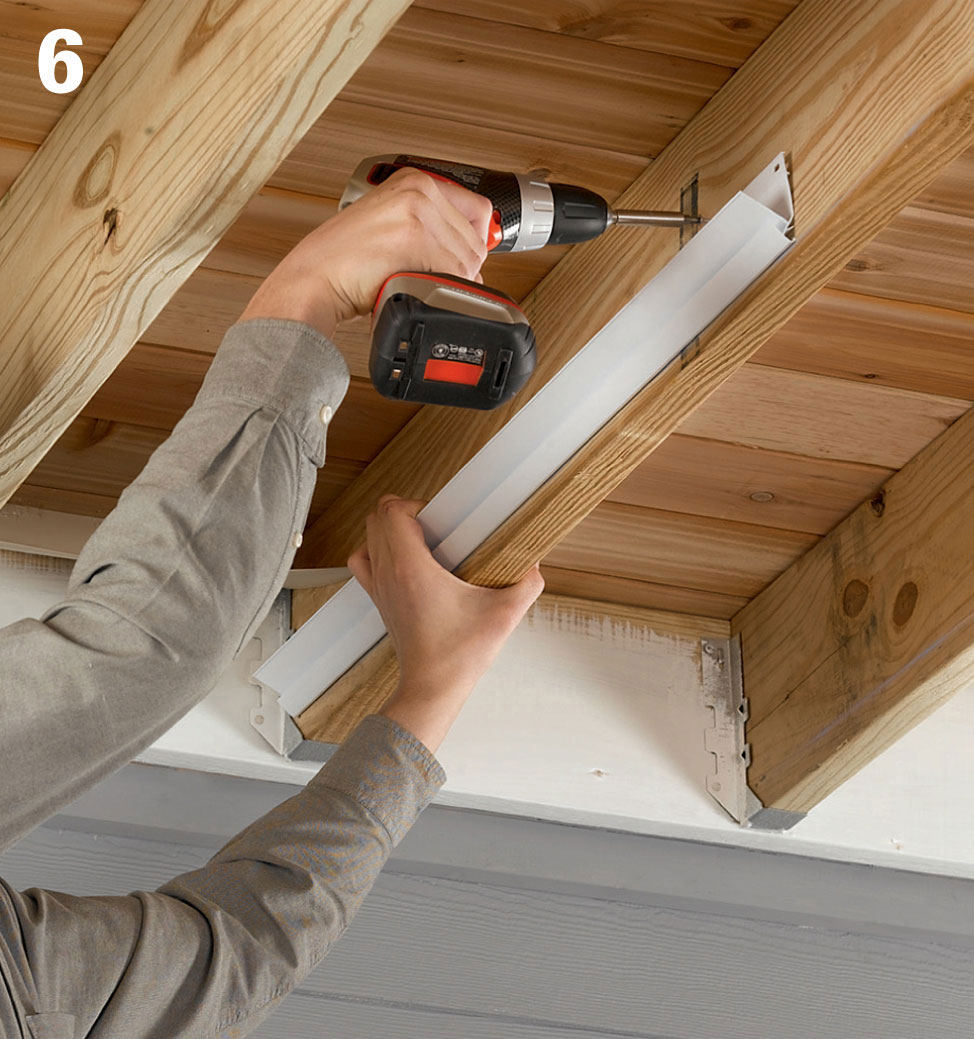
Begin installing the joist rails, starting 1" away from the ledger. Position each rail with its bottom edge on the chalk line and fasten it to the joist at both ends with 1" stainless steel screws, then add one or two screws in between. Avoid over-driving the screws and deforming the rail; leaving a little room for movement is best.
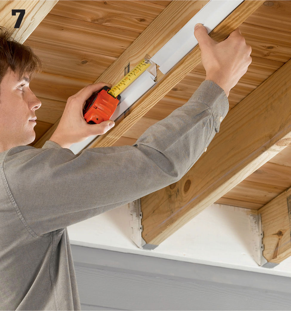
Install the remaining rails on each joist face, leaving a 1 1/2" (minimum) to 2" (maximum) gap between rails. Install rails along both sides of each interior joist and along the insides of each outside joist. Trim the final rail in each row as needed, using aviation snips.
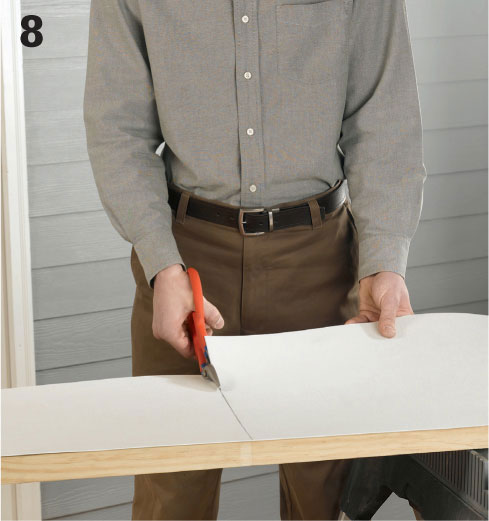
Measure the full length of each joist cavity, and cut a collector panel 1/4" shorter than the cavity. This allows room for expansion of the panels. For narrower joist cavities, trim the panel to width following the manufacturer’s sizing recommendations.
Scribe and trim collector panels for a tight fit against the ledger board. Hold a carpenter’s pencil flat against the ledger, and move the pencil along the board to transfer its contours to the panel. Trim the panel along the scribed line.
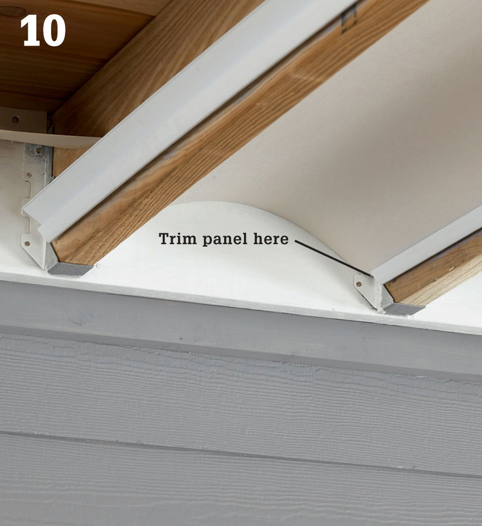
Trim the corners of collector panels as needed to accommodate joist hangers and other hardware. This may be necessary only at the house side of the joist cavity; at the outer end, the 1/4" expansion gap should clear any hardware.
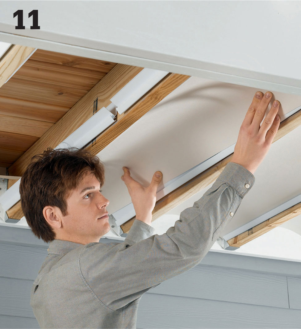
Install the collector panels, starting at the house. With the textured side of the panel facing down, insert one side edge into the joist rails, and then push up gently on the opposite side until it fits into the opposing rails. When fully installed, the panels should be tight against the ledger and have a 1/4" gap at the rim joist.
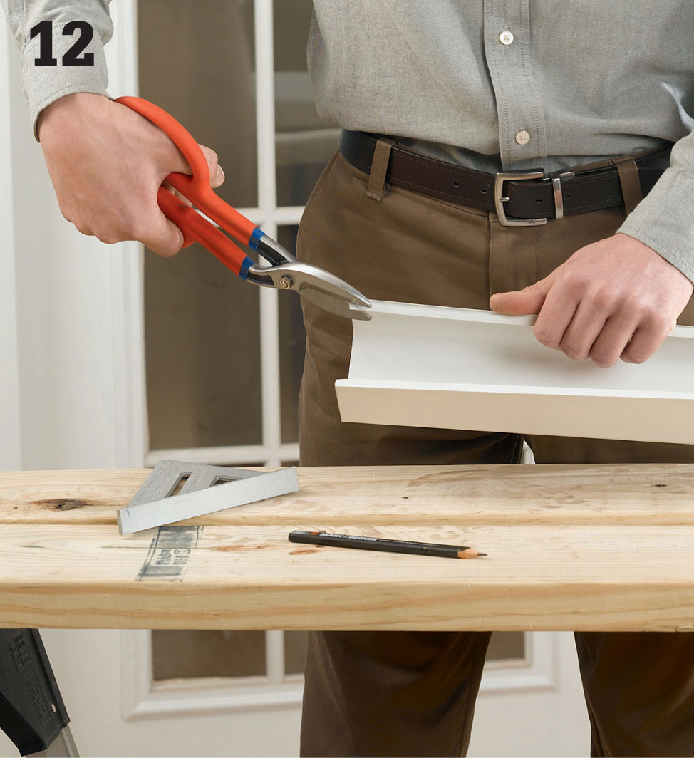
Prepare each joist gutter by cutting it 1/4" shorter than the joist it will attach to. If the joists rest on a structural beam, see Working Around Beams, on page 260. On the house end of each gutter, trim the corners of the flanges at 45°. This helps the gutter fit tightly to the ledger.
Cut four or five 1/8" tabs into the bottom surface at the outside ends of the gutters. This helps promote the drainage of water over the edge of the gutter.
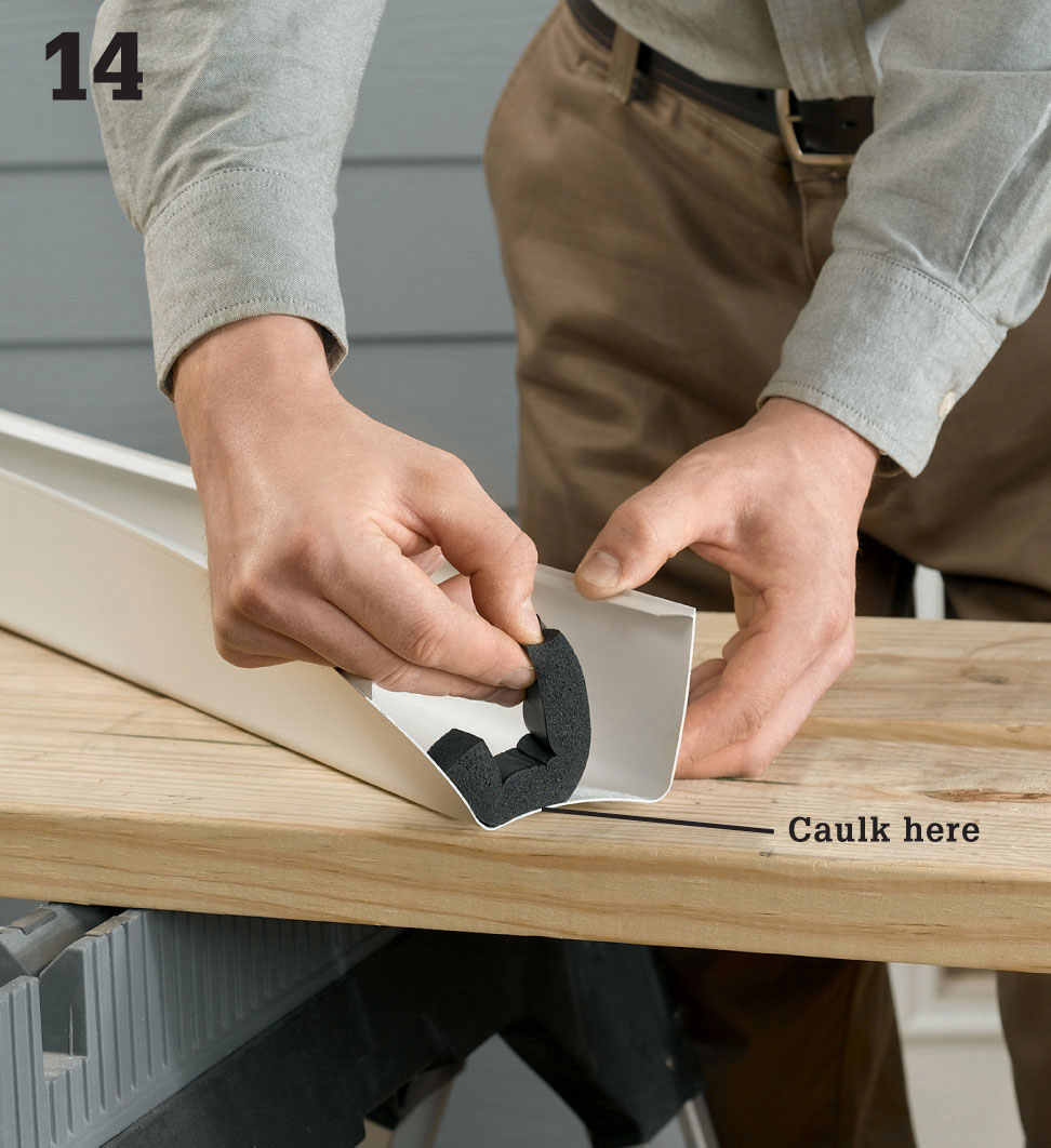
Attach self-adhesive foam weatherstrip (available from the manufacturer) at the home-end of each joist gutter. Run a bead of caulk along the foam strip to water-seal it to the gutter. The weatherstrip serves as a water dam.
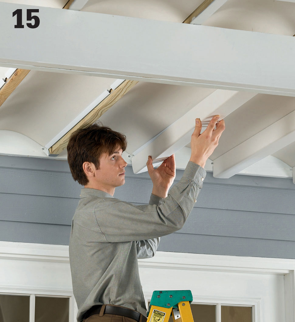
Install each joist gutter by spreading its sides open slightly while pushing the gutter up onto the joist rails until it snaps into place. The gutter should fit snugly against the collector panels. The gutter’s home-end should be tight against the ledger, with the 1/4" expansion gap at the rim joist.
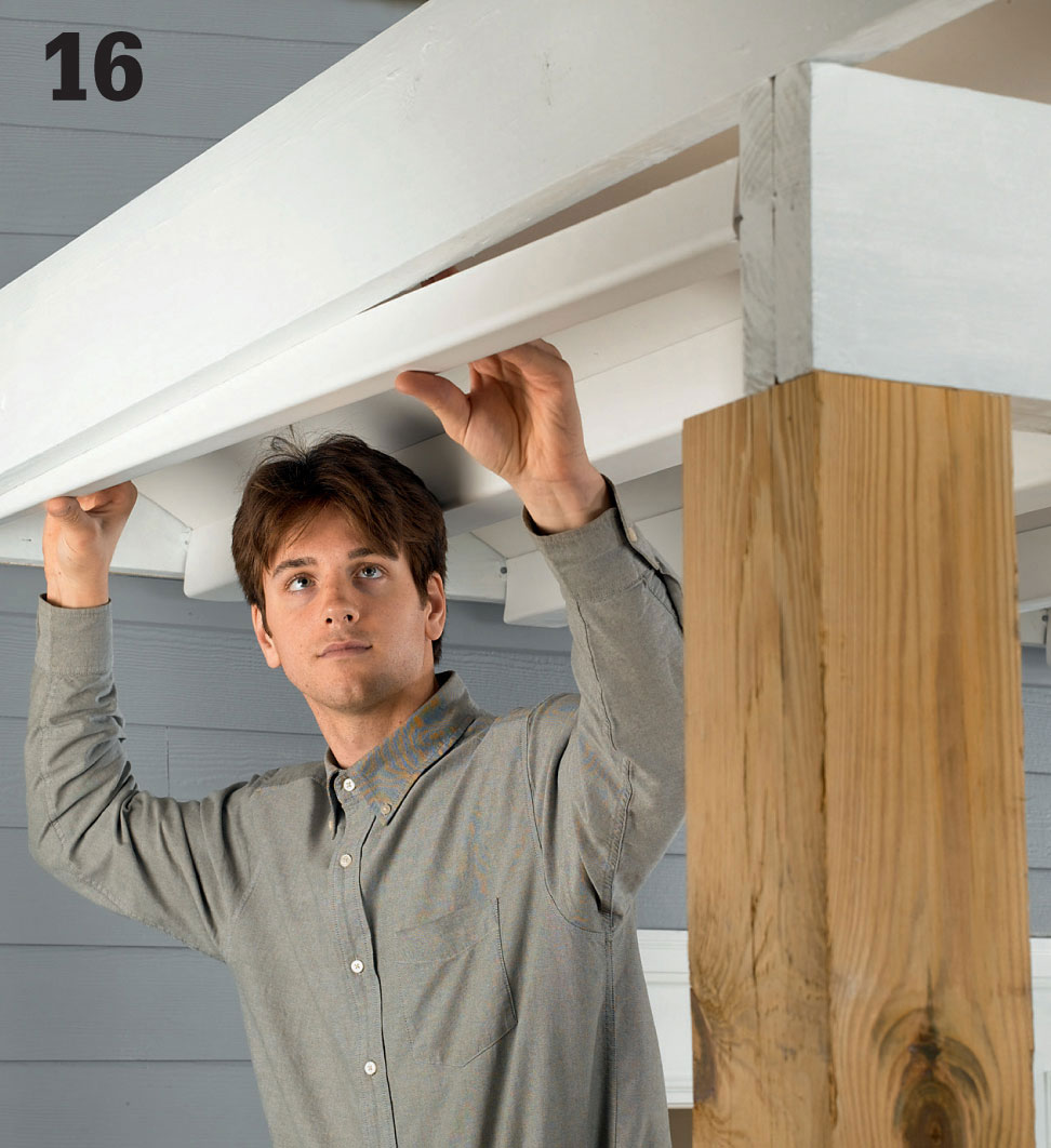
Prepare the boundary gutters following the same steps used for the joist gutters. Install each boundary gutter by slipping its long, outside flange behind the joist rails and pushing up until the gutter snaps into place. Install the boundary gutters working from the house side to the outer edge of the deck.
Run a bead of color-matched caulk along the joint where the collector panels meet the ledger board. This is for decorative purposes only and is not required to prevent water intrusion.
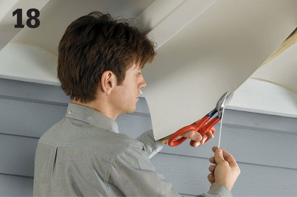
If collector panels are misshapen because the joist spacing is too tight, free the panel within the problem area, then trim about 1/8" from the side edge of the panel. Reset the panel in the rails. If necessary, trim the panel edge again in slight increments until the panel fits properly.
 Runoff Gutters
A basic gutter system for a square or rectangular deck includes a straight run of gutter channel with a downspout at one end. Prefabricated vinyl or aluminum gutter parts are ideal for this application. Gutter channels are commonly available in 10-ft. and 20-ft. lengths, so you might be able to use a single channel without seams. Otherwise, you can join sections of channel with special connectors. Shop around for the best type of hanger for your situation. If there’s limited backing to support the back side of the channel or to fasten into, you may have to use strap-type hangers that can be secured to framing above the gutter.
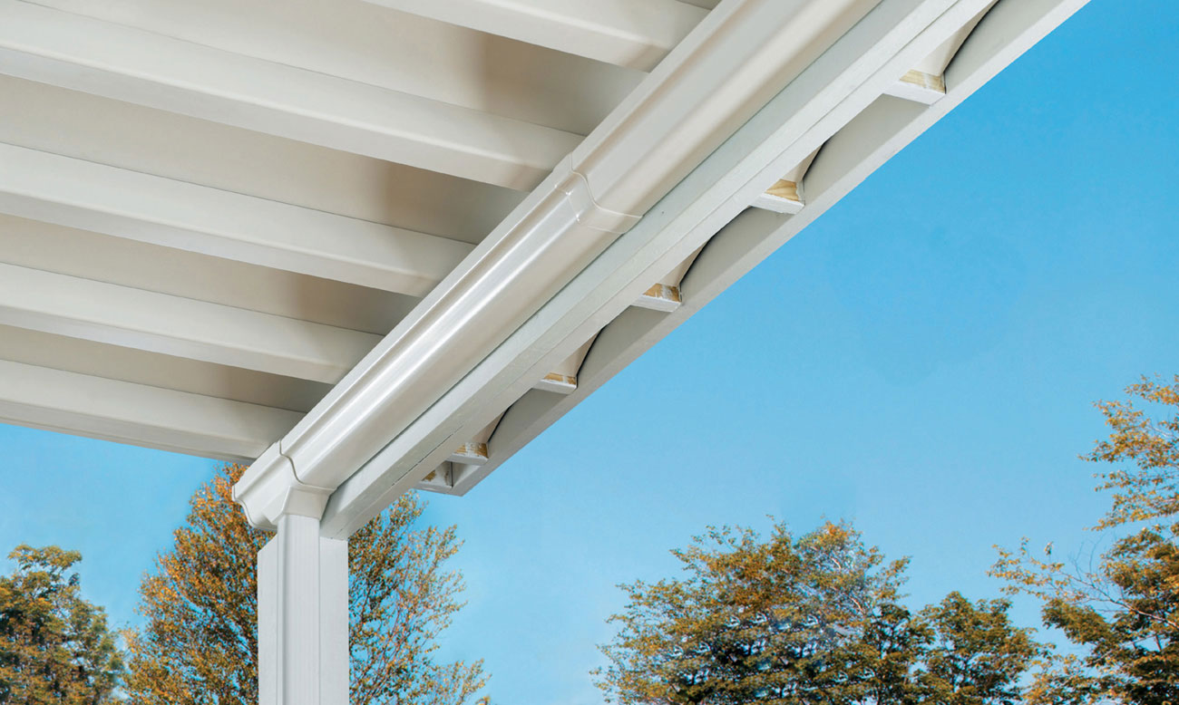
 How to Install an Under-deck Runoff Gutter
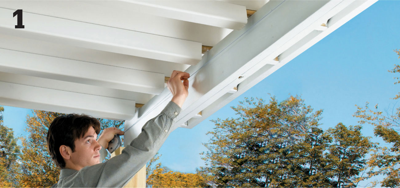
Snap a chalk line onto the beam or other supporting surface to establish the slope of the main gutter run. The line will correspond to the top edge of the gutter channel. The ideal slope is 1/16" per foot. For example, with a 16-ft.-long gutter, the beginning is 1" higher than the end. The downspout should be located just inside the low end of the gutter channel. Mark the beam at both ends to create the desired slope, then snap a chalk line between the marks. The high end of the gutter should be just below the boundary gutter in the ceiling system.
Install a downspout outlet near the end of the gutter run so the top of the gutter is flush with the slope line. If you plan to enclose the area under the deck, choose an inconspicuous location for the downspout, away from traffic areas.
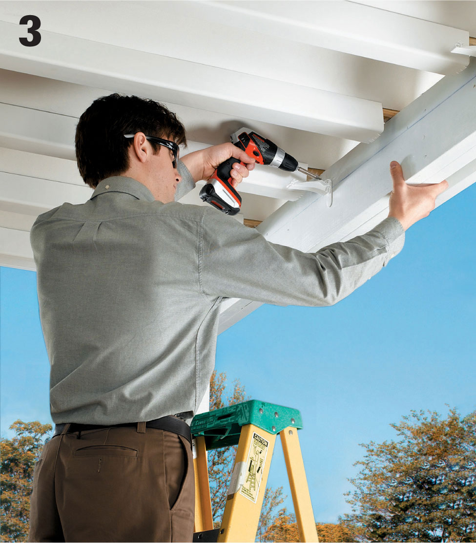
Install hanger clips (depending on the type of hangers or support clips you use, it is often best to install them before installing the gutter channel). Attach a hanger every 24" so the top of the gutter will hang flush with slope line.
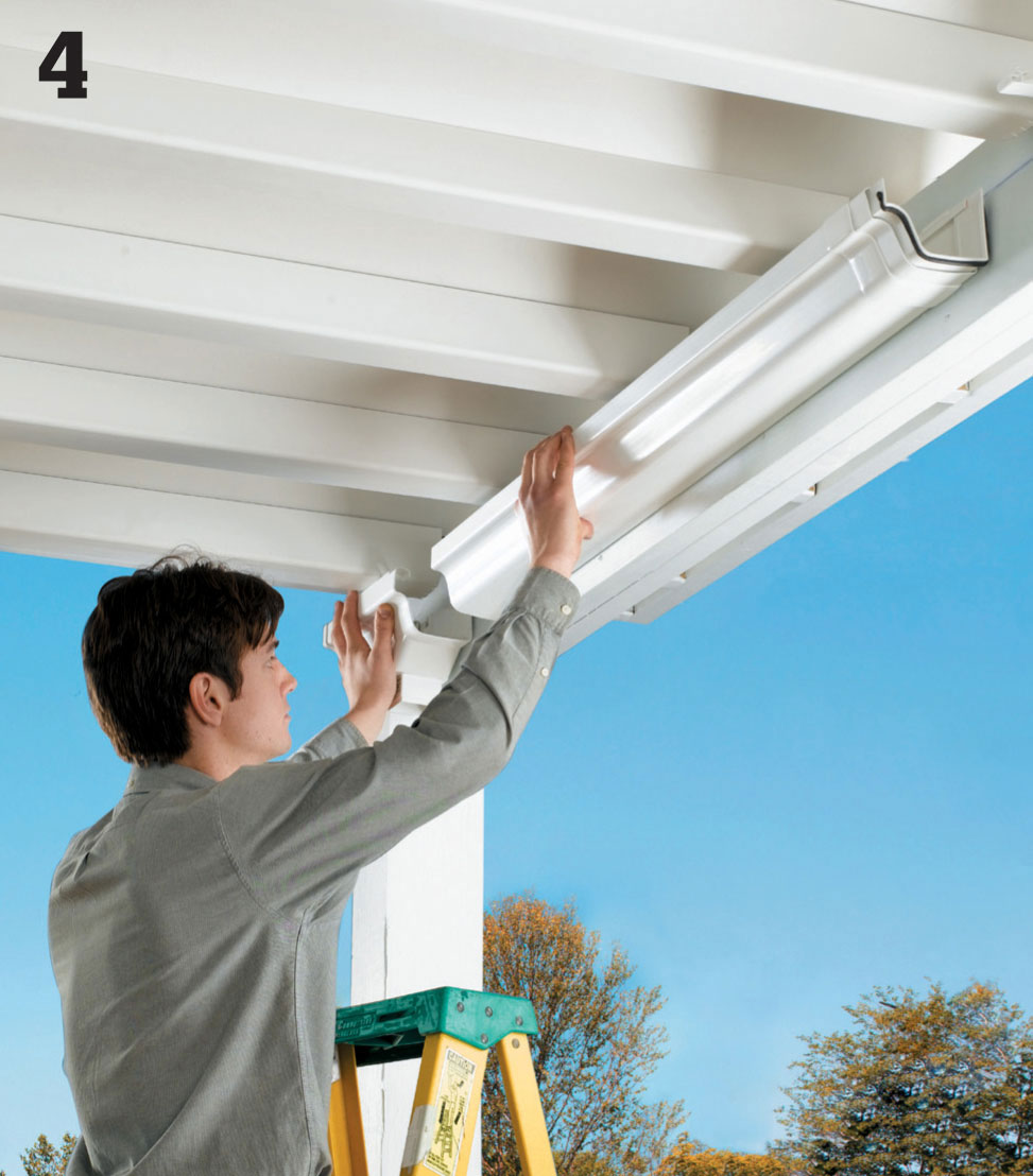
Cut sections of gutter channel to size using a hacksaw. Attach an end cap to the beginning of the main run, then fit the channel into the downspout outlet (allowing for expansion, if necessary) and secure the gutter in place.
Join sections of channel together, if necessary, using connectors. Install a short section of channel with an end cap on the opposite side of the downspout outlet. Paint the area where the downspout will be installed if it is unpainted.
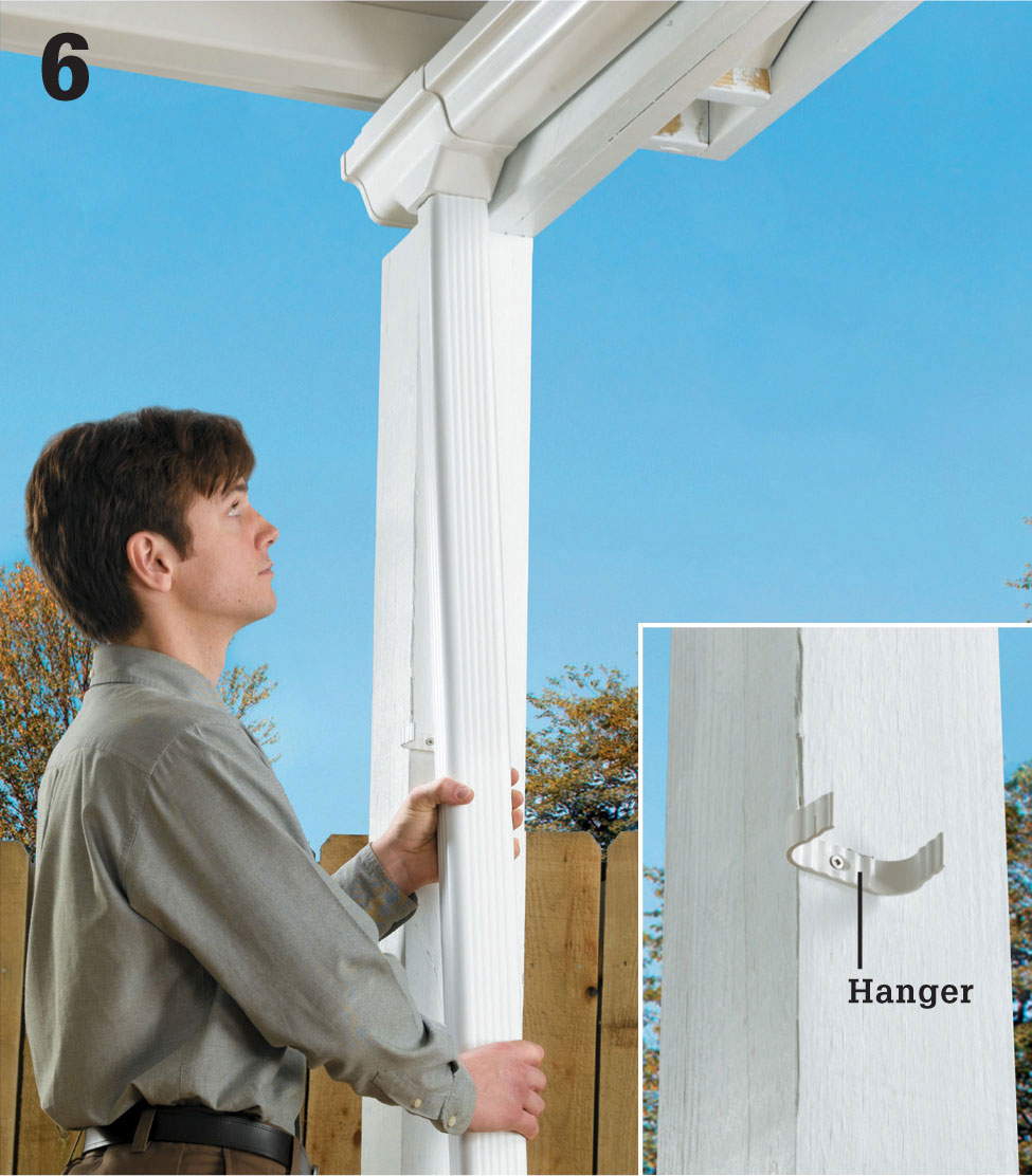
Cut the downspout piping to length and fasten an elbow fitting to its bottom end. Attach the downspout to the downspout outlet, then secure the downspout to a post or other vertical support using hangers (inset).

Cut a drain pipe to run from the downspout elbow to a convenient drainage point. Position the pipe so it directs water away from the house and any traffic areas. Attach the pipe to the downspout elbow. Add a splash block, if desired.
 Spa Tub Deck
Building a spa tub into a deck is usually done in one of two ways. If you design your deck at exactly the right height, you can create a full inset by resting the tub on a concrete pad and building the deck around it.
But on a low-profile deck, or a tall deck, the most practical solution is to mount the tub on the surface of the deck and build a secondary platform around it, creating a partial inset. As shown on the following pages, the structural design of the deck must be modified to ensure that it can support the added weight of a spa tub filled with water. Make sure your deck plans are approved by the building inspector before you begin work.
Installing a spa tub usually requires the installation of new plumbing and electrical lines. When planning the installation, make sure to consider the location of plumbing pipes, electrical cables, switches, and access panels. For convenience, arrange to have the rough-in work for these utilities done before you install the decking boards.
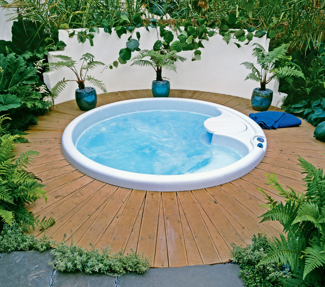
Whether the tub is inset into the deck or rests on top, adding a spa tub is a very popular deck improvement project.
 Gallery of Spa Tub Decks
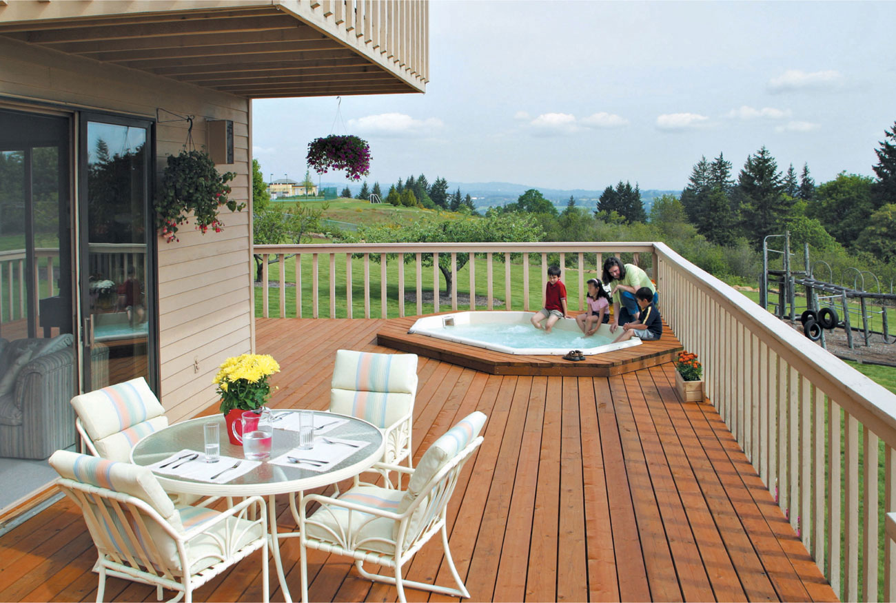
Hot tubs aren’t limited to ground-level decks. However, you’ll need to plan for additional framing and footings to support the tub safely, whatever the height of your deck may be. Here’s another important reason why your deck plans should be reviewed by a building inspector before you build.
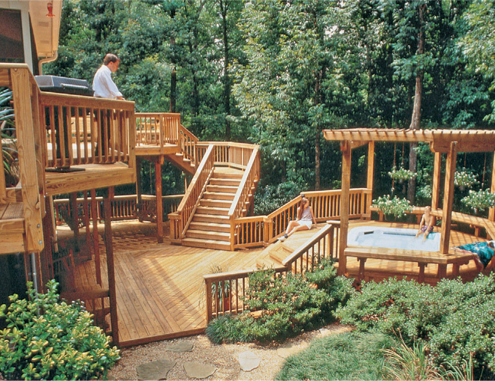
When planning for a spa tub, consider locating it in a space that’s adjacent to your primary deck. That way, the tub won’t interfere with traffic patterns or block larger spaces you may need for tables, other patio furniture, or groups of people.
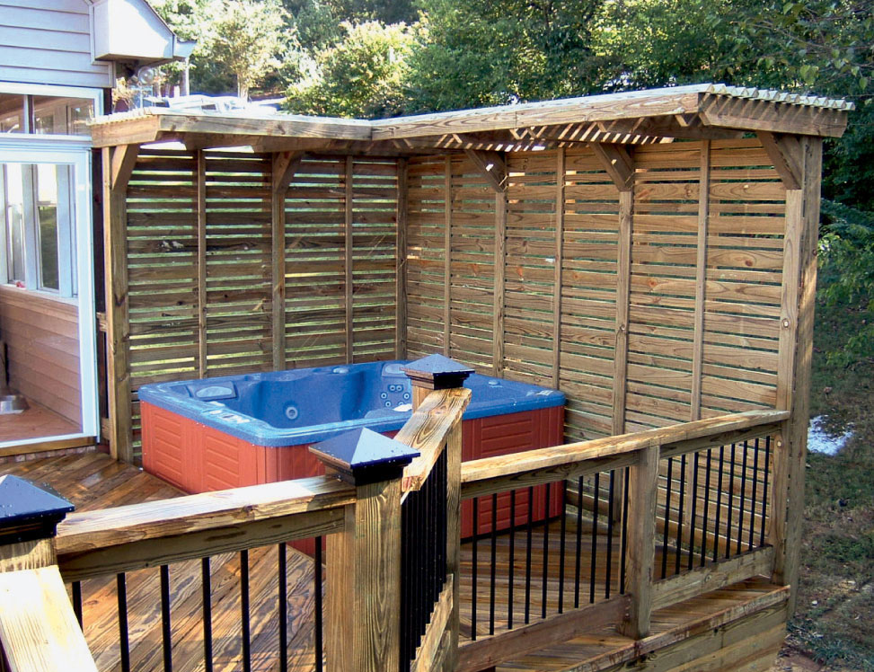
If your yard doesn’t offer much privacy for a tub, it’s easy to create some by building a privacy wall onto your deck. A colored fabric wind shade could serve the same purpose. Now, you’ll be able to enjoy your soaks or tanning time with a greater sense of peace.
 Planning for Spa Tubs
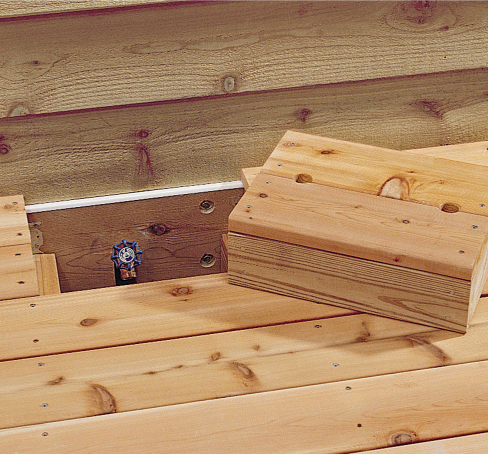
An access hatch made from decking can hide a utility feature, such as a water faucet or air-conditioner compressor. Install cleats along the inside of the framed opening to support the hatch. Construct the hatch from decking boards mounted on a 2 × 4 frame. Finger holes drilled in the hatch make removal easier.
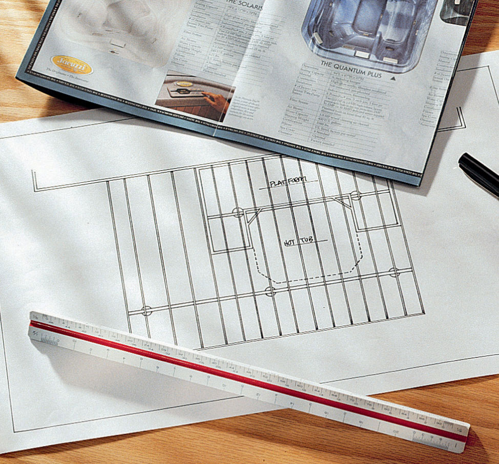
Plan posts and beams to support the maximum anticipated load, including the weight of the spa tub filled with water. In most cases, this means altering your deck plan to include extra beams and posts directly under the tub.
 How to Build a Spa Tub Deck
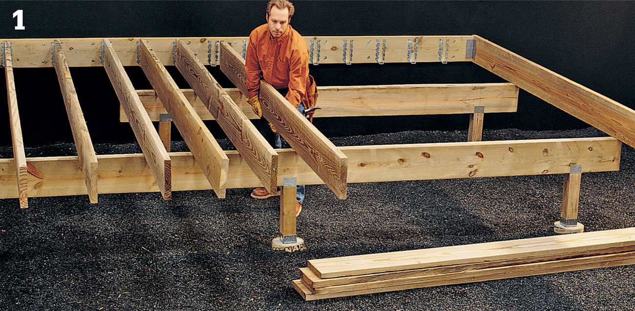
Lay out and install the ledger, footings, posts, and support beams, according to your deck plans. Lay out joist locations on the ledger and beams, and install the joists, following local code requirements. Many building codes require joists spaced no more than 12" on center if the deck will support a spa tub. If your spa tub requires new plumbing or electrical lines, have the preliminary rough-in work done before continuing with deck construction.
Install the decking boards, then snap chalk lines to outline the position of the tub and the raised platform that will enclose the tub.
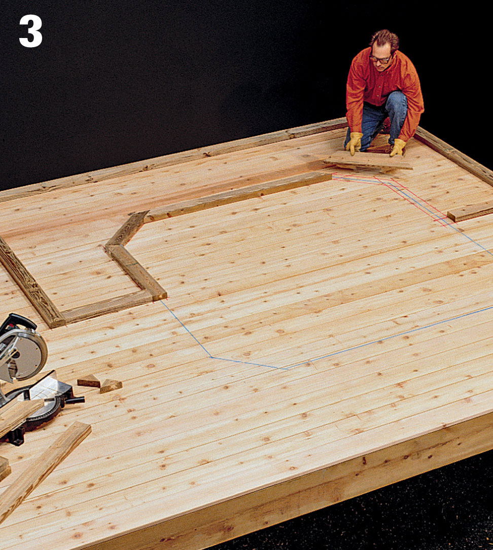
Lay out and cut 2 × 4 sole plates and top plates for the stud walls on the raised platform.
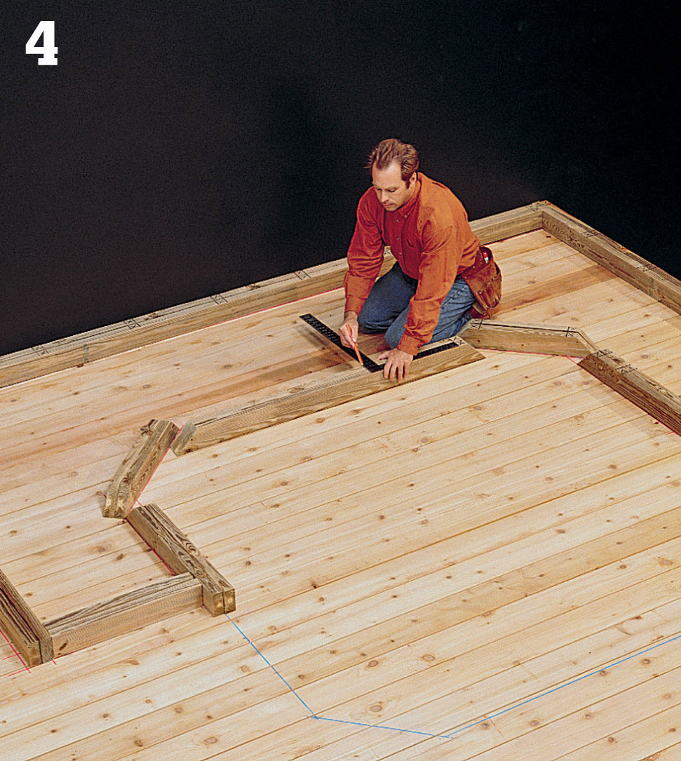
Mark stud locations on the top and bottom plates. Studs should be positioned every 16" (measured on center), and at the ends of each plate.
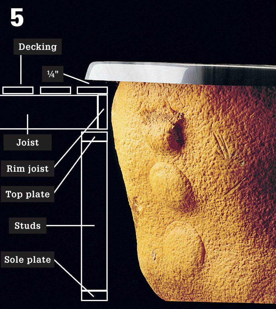
Measure the height of the spa tub to determine the required height of the studs in the platform walls. Remember to include the thickness of both wall plates, the joists that will rest on the walls, and the decking material on the platform. The surface of the finished platform should be 1/4" below the lip of the spa tub.
Construct the stud walls by screwing the plates to the studs. Position the walls upright on the deck over the outline marks, and anchor them to the deck with 2-1/2" deck screws.
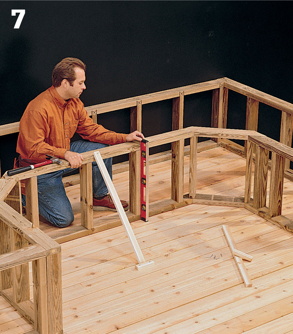
At the corners, fasten the studs together with 3" deck screws. Check the walls for plumb, and brace them in position.
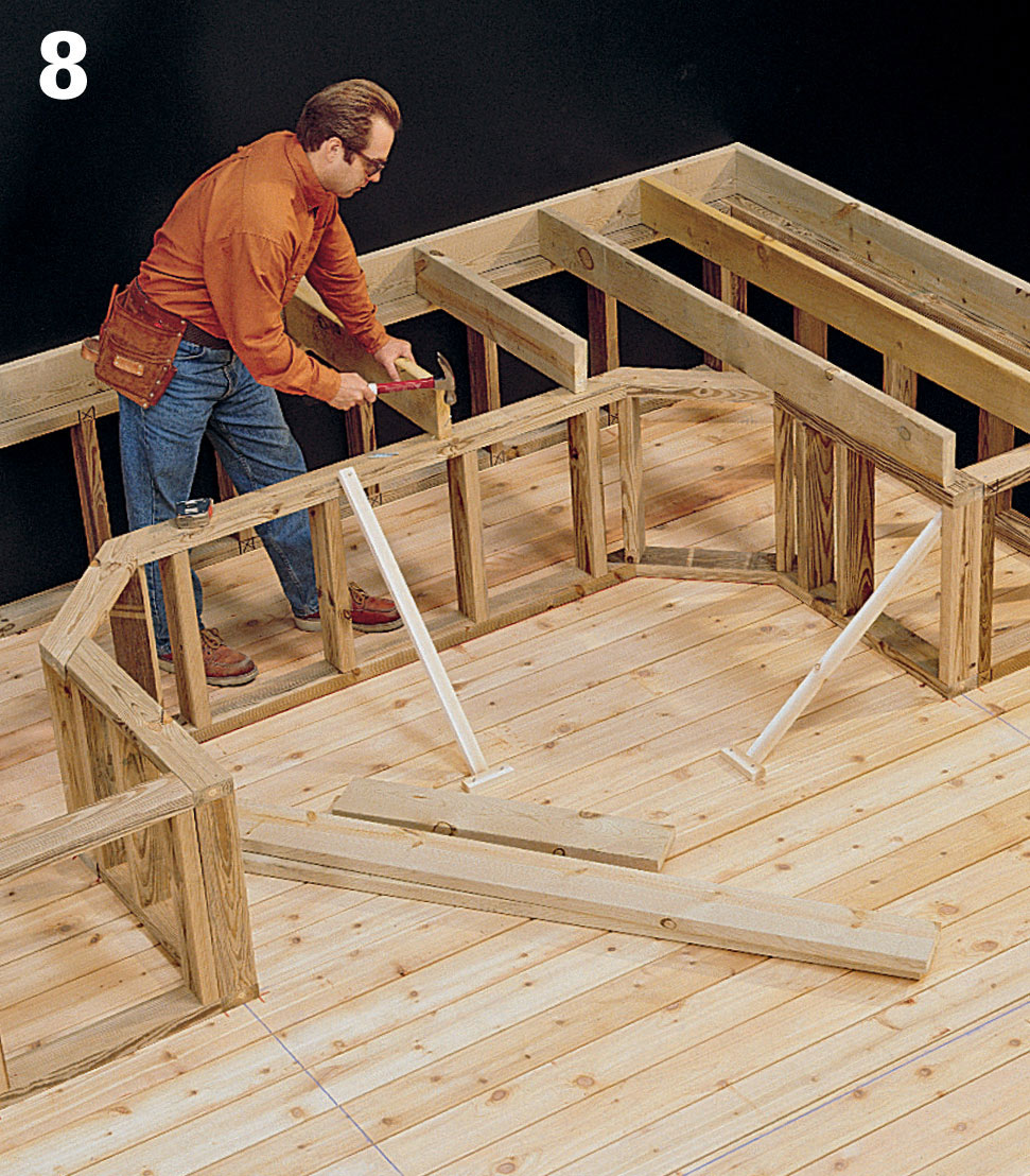
Toenail a 2 × 6 rim joist along the back edge of the platform, then cut and install 2 × 6 joists across the top of the stud walls at 16" intervals, toenailing them to the top plates. The ends of the joists should be set back 1 1/2" from the edges of the top plates to allow for the rim joist.
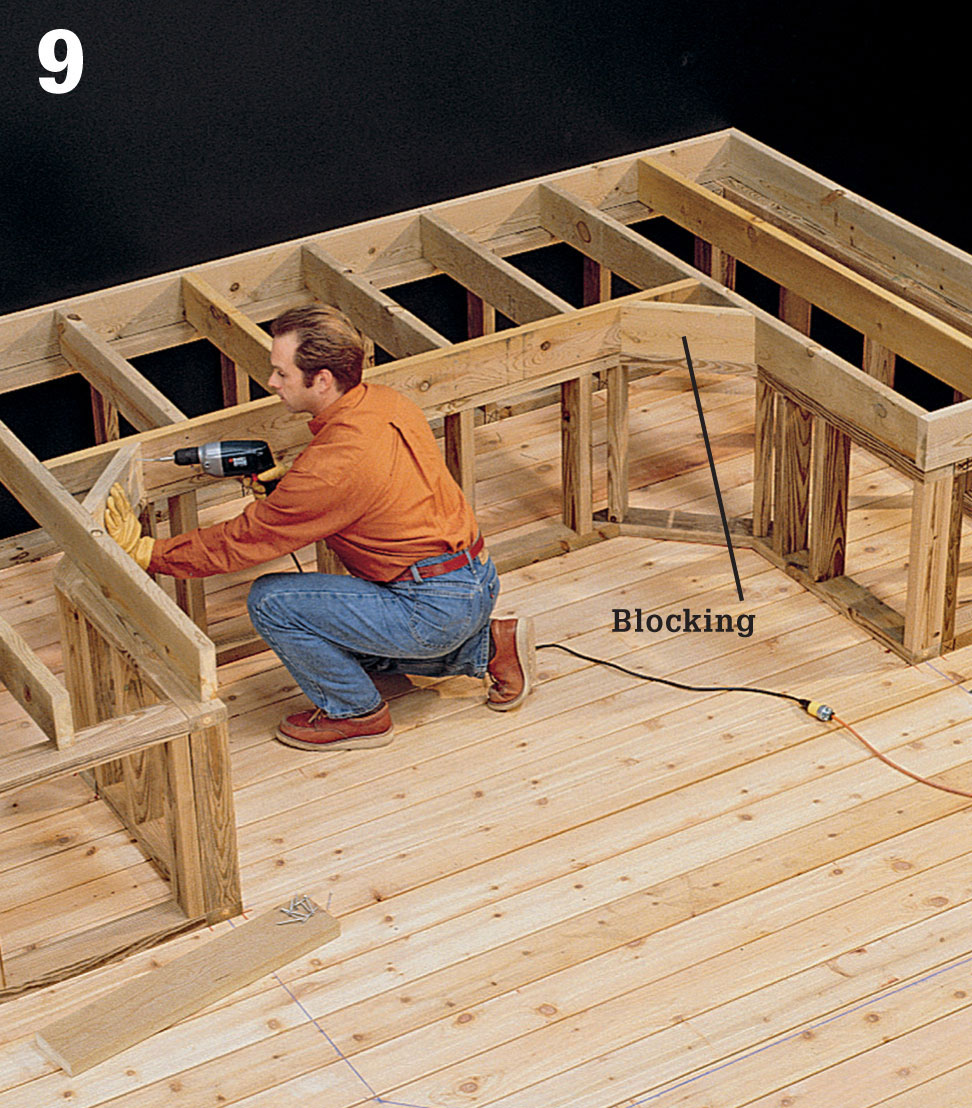
Cut 2 × 6 rim joists to length, and endnail them to the joists with 16d nails. At angled wall segments, cut diagonal blocking and attach it between the rim joist and adjoining joists with deck screws.
Cut decking boards, and attach them to the platform joists with 2-1/2" deck screws. If your spa tub requires cutouts for plumbing or electrical lines, do this work now.
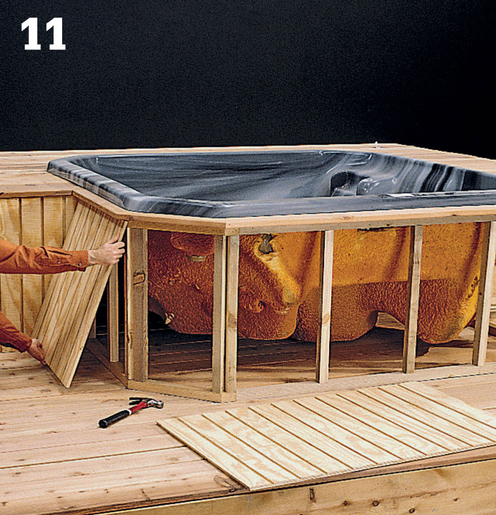
Set the tub in place so it rests on the deck—the rim should not bear weight. Build 2 × 2 stud walls around the exposed sides of the tub. Measure, cut, and install siding materials on the exposed walls.
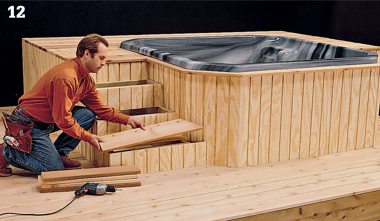
Build platform steps to provide access to the platform using siding materials to box in the risers. Where required by code, install railings around the elevated platform.
 Boardwalk Deck on a Slab
There’s no need to let a cracked, aging concrete patio ruin the look and enjoyment of your backyard. You can build a very simple deck platform right over the failing slab with very little effort or expense. Make no mistake though, the result will be a beautiful new outdoor platform that improves the look of the home and the yard.
This is an independent deck; the structure is not attached to the house, but is instead laid atop the slab and allowed to move with any shifting in the concrete. It’s constructed on a simple frame base laid level with sleepers over the concrete itself. This means that the deck will be very close to the ground and subject to a great deal of moisture. Only certain types of decking will tolerate those conditions. We’ve used pressure-treated pine deckboards.
The design of the deck is a plain rectangle and can easily be constructed over a weekend. We’ve spruced up the look a bit by laying the decking in a standard “Boardwalk” pattern. More complex patterns would make the deck surface look even more impressive—just remember to do yourself a favor and work the patterns out on graph paper before cutting any decking. Proper planning will inevitably save a lot of waste.
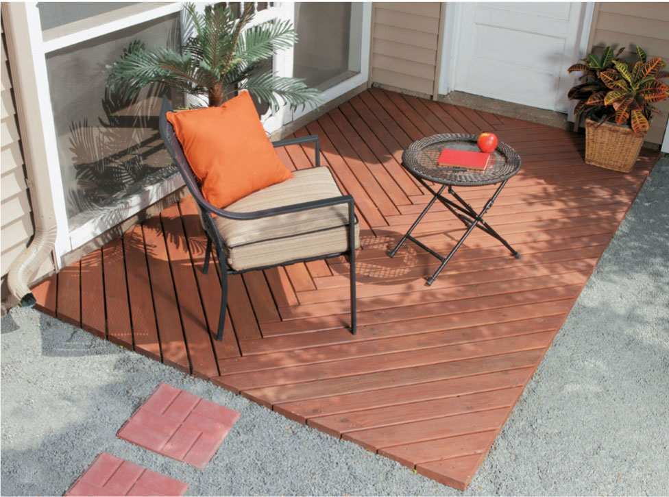
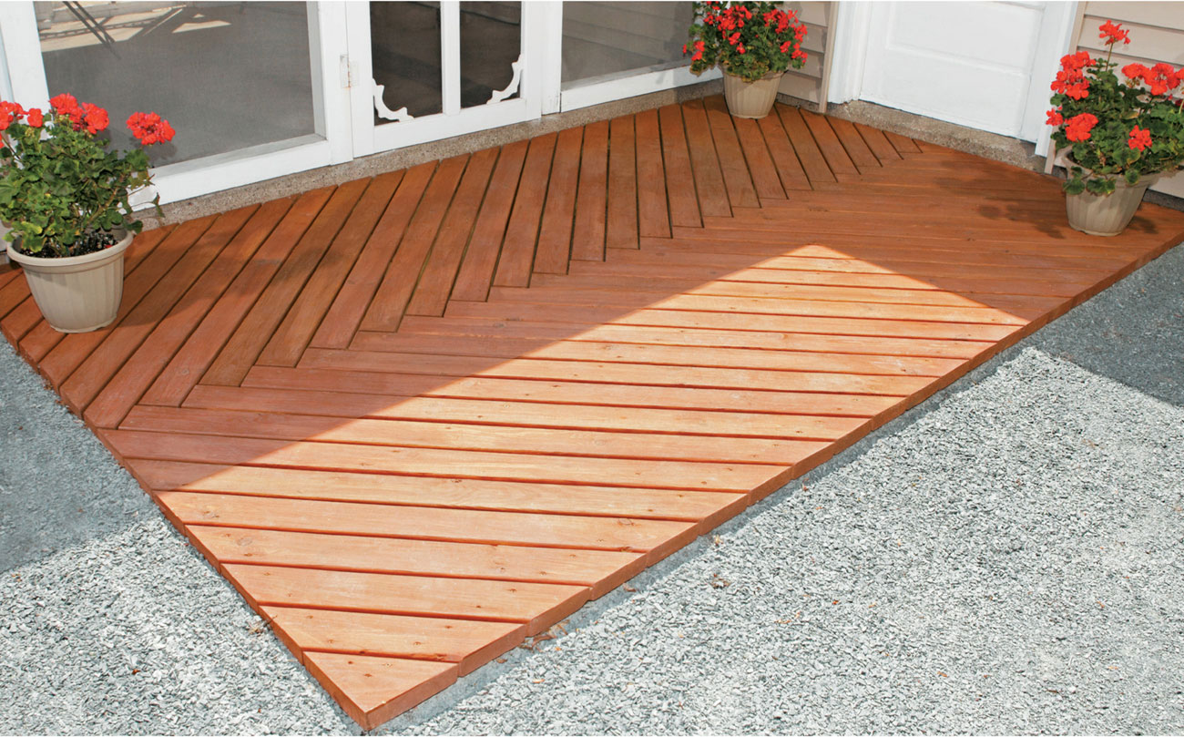
Turn a boring or failing concrete slab into an attractive walkout or entertainment space with a short utility or “Boardwalk” deck installed on top of it.
Supplies
Galvanized metal corner brackets (16)
2-1/2" galvanized deck screws
2" composite shims
Circular saw
Miter saw
Power drill and bits
Treated lumber (2 × 4 and 2 × 2)
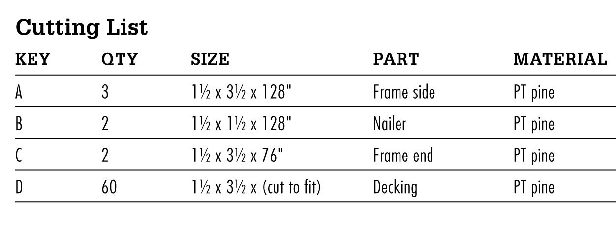
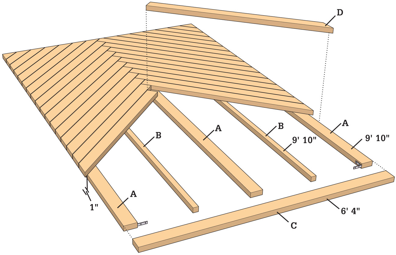
 How to Build a Boardwalk Deck
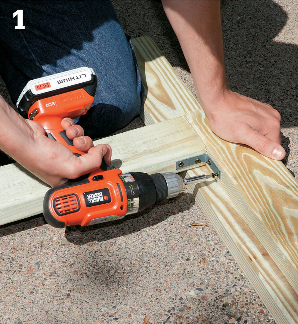
Build and assemble the frame offsite by cutting and measuring 10-ft. 2 × 4s to length and securing them together with galvanized metal corner brackets.
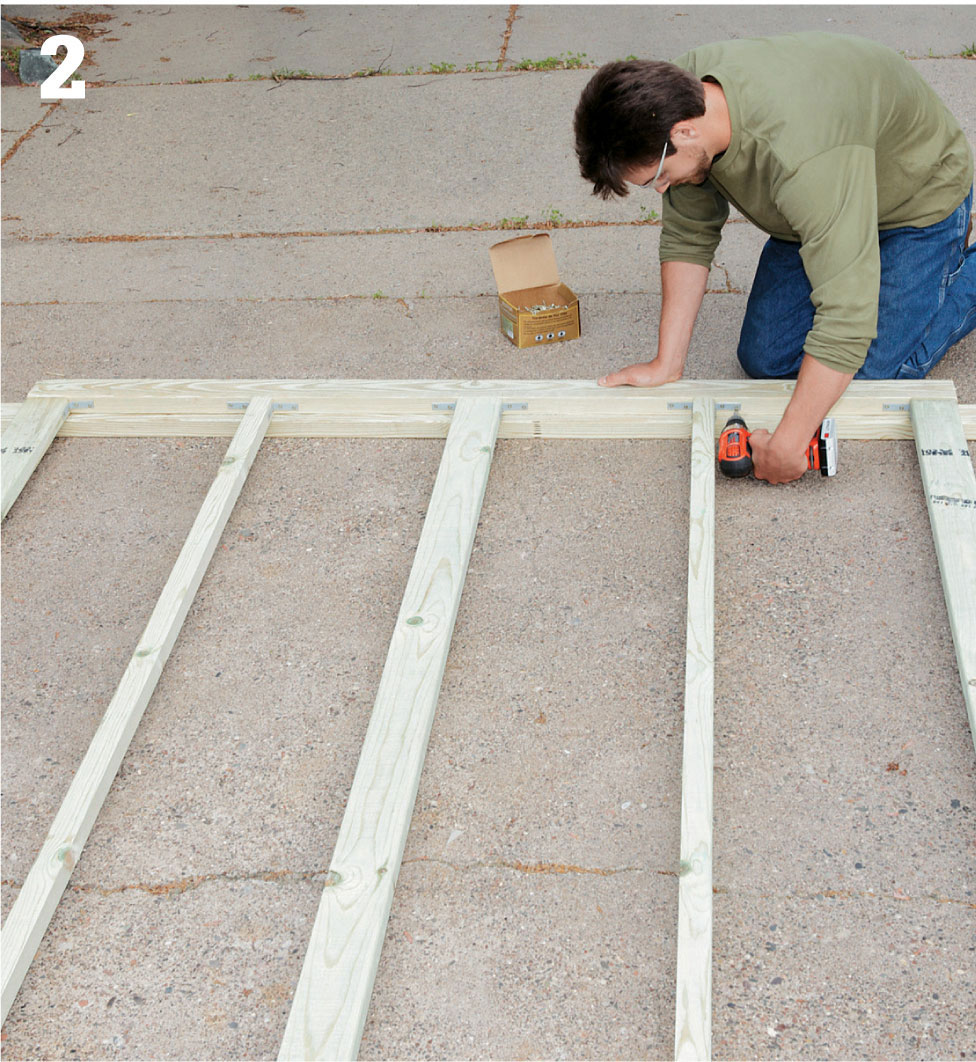
Install the nailer joists by measuring and cutting parallel boards to the length of the frame. Use 2" deck screws and galvanized metal corner brackets to secure the nailer joists to the frame.
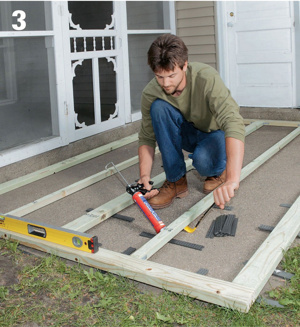
Clear away any dust and debris from the concrete slab. Set the frame atop the slab and use 8" plastic shims to level it. Glue shims in place and cut off excess so shims are flush with the frame.
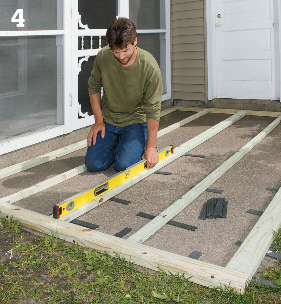
Use a level as you work with the shims to ensure an even plane on which to build the deck.
Remove the frame from the slab before installing the decking. Stagger the 2 × 4s in a crosshatch pattern in opposing 45° angles from the center nailing joist. Attach the boardwalk pattern to the frame using 3" deck screws. Boards should abut one another the length of the joist and allow for at least 1" of overhang from the frame.
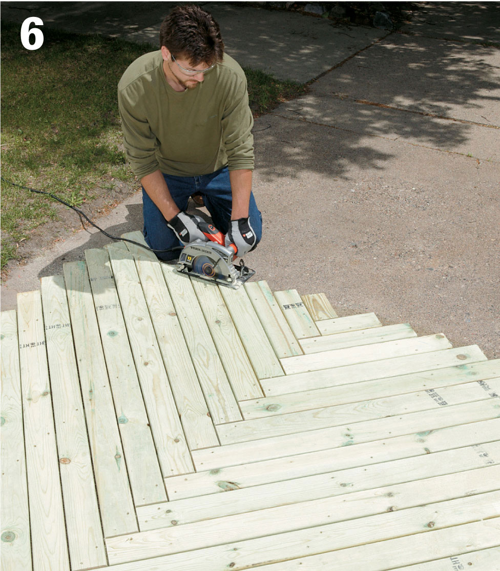
Mark 1" overhang on all sides of the frame using a chalk-line, and cut off excess decking using a circular saw equipped with a carbide blade.
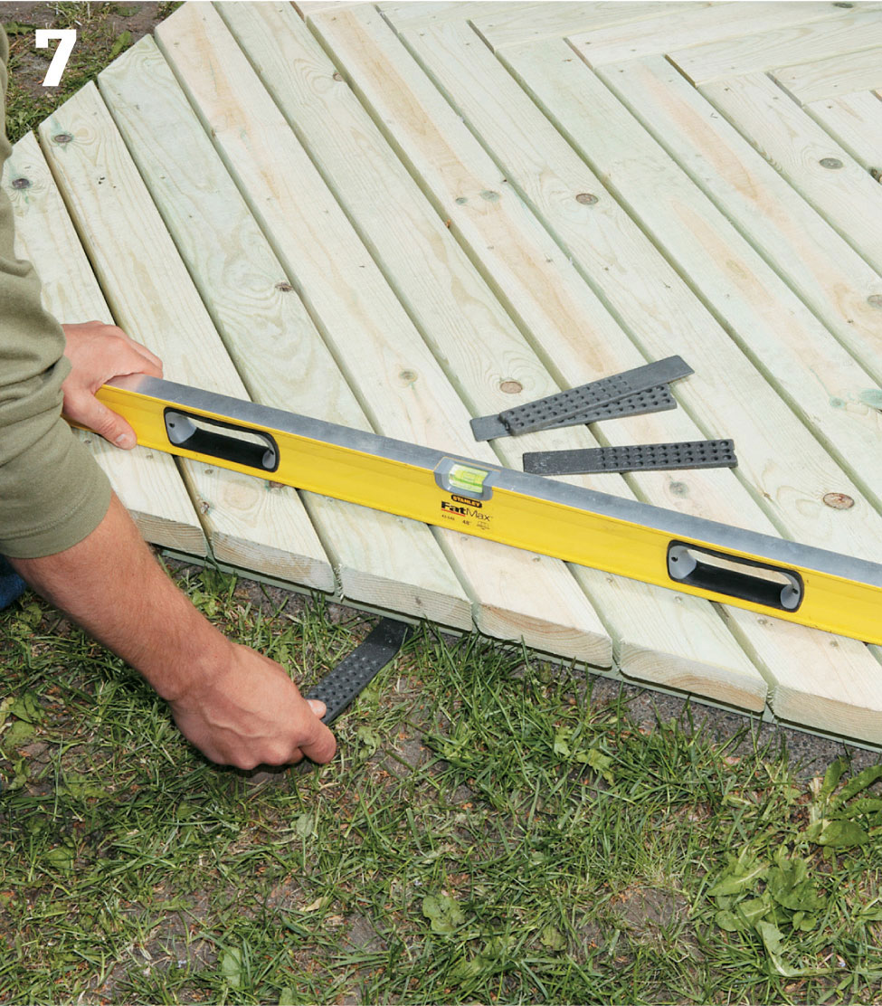
Use a helper to install the decking atop the concrete slab, checking for level and using shims to adjust as necessary.
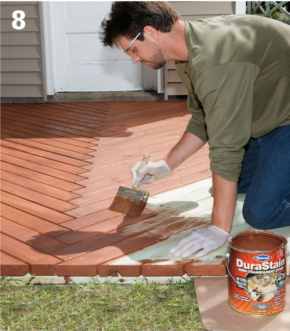
Clear away dust and debris and stain the decking as desired.
 Floating Octagon Island Deck
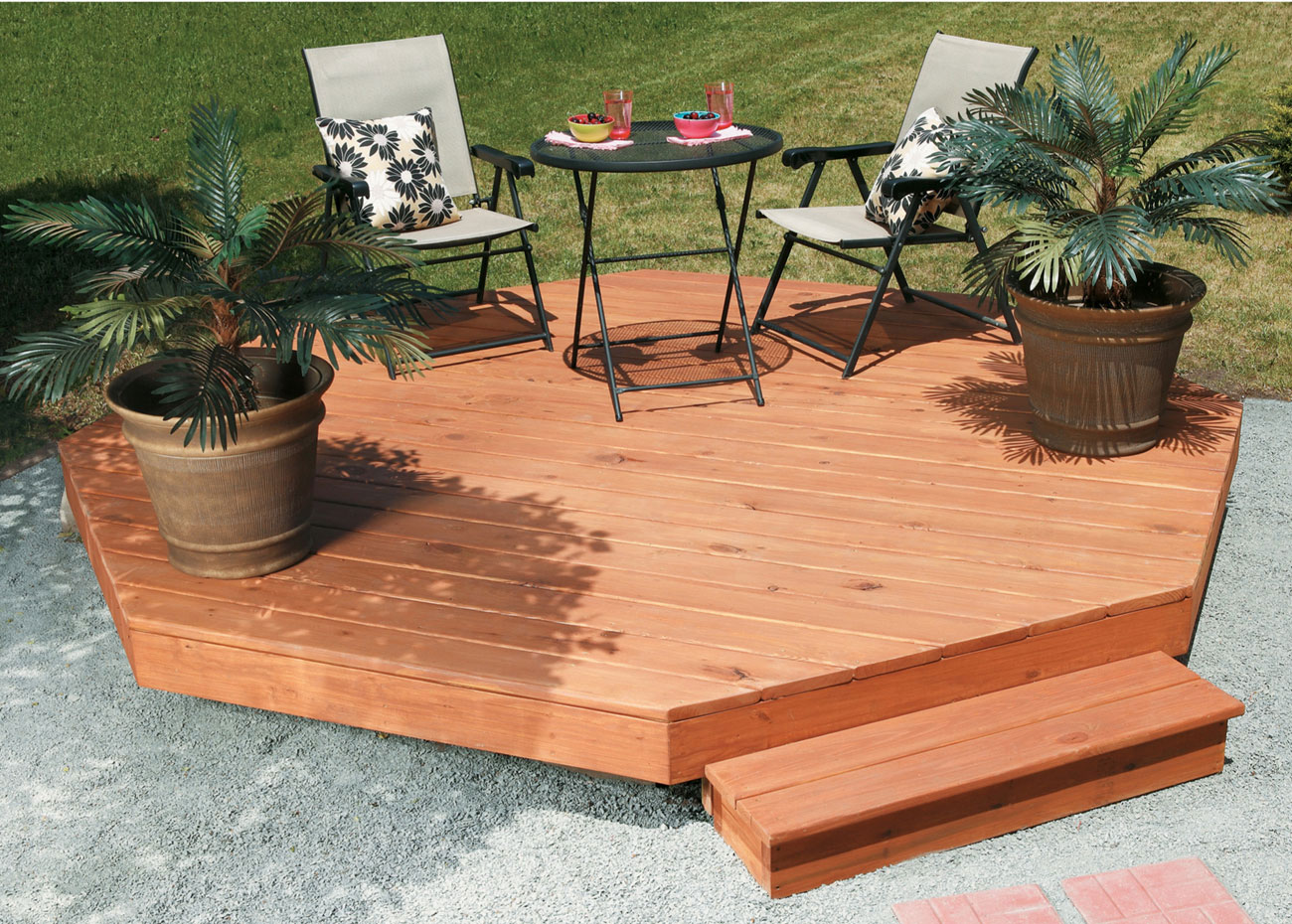
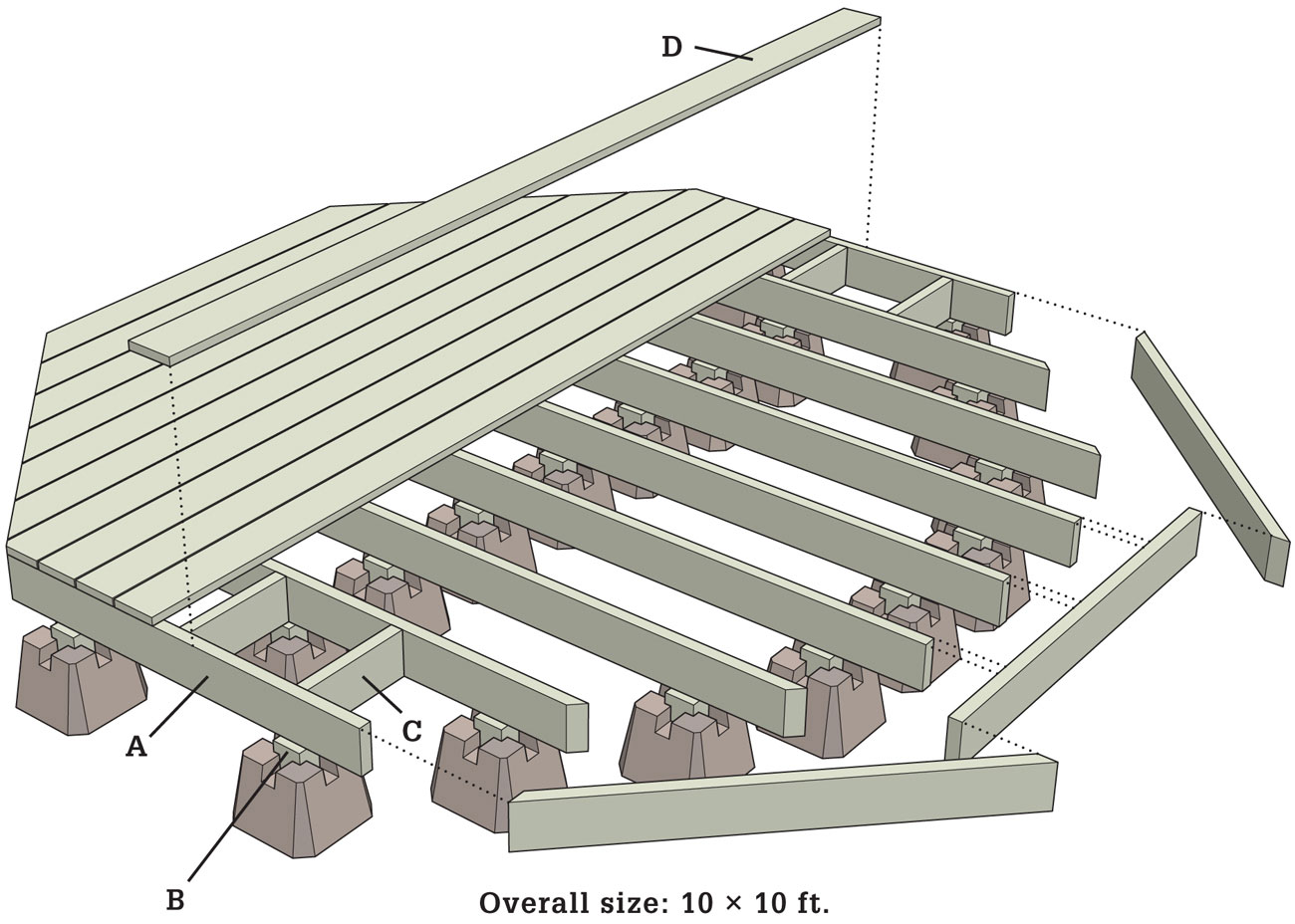
Sometimes all you need is a simple, easy-to-build platform to complete an otherwise perfect backyard. The project shown here is an “island deck,” detached from the house and requiring no ledger attachment.
That means it has the simplest of foundations; a set of pre-cast concrete pier blocks that are simply set in place, making them far easier to work with than poured footings. The piers are cast to a standardized shape and size: 10" square and 10" high, with slots in the top to accommodate joists and posts. Because the pier blocks are not secured in the ground, the deck “floats.” This allows for movement in response to settling and the freeze-thaw cycle of the soil. Floating pier decks meet most local codes—but check yours just to be sure.
This deck is also low enough to the ground that it won’t require a handrail (unless, in your particular case, the yard slopes severely off to one side).
Supplies
Dek-Block brand pier blocks (25)—see Resources, page 347
3" galvanized deck screws
Circular saw
Miter saw
Power drill and bits
Stain or sealer
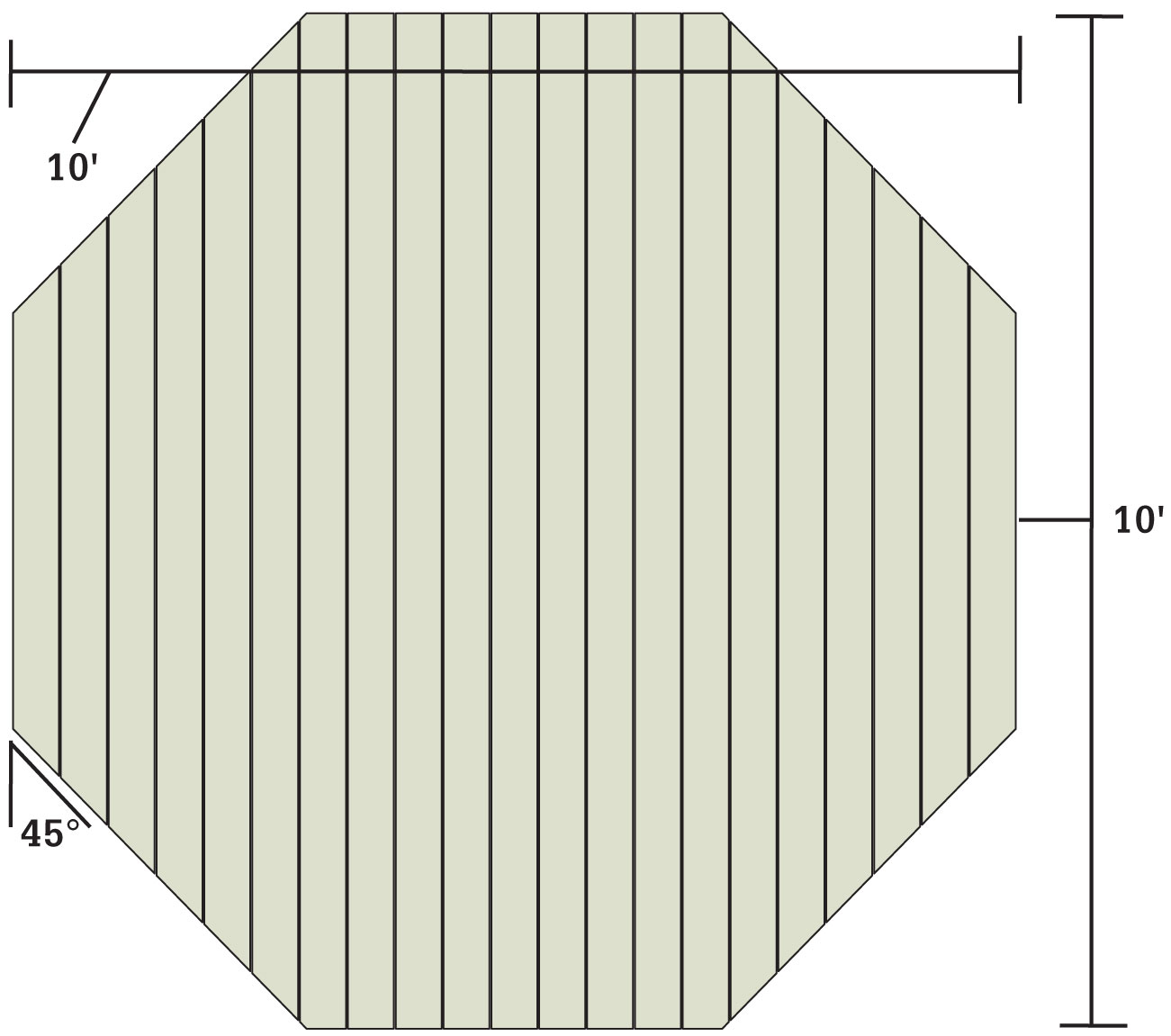
Decking Detail
 How to Build a Floating Octagon Deck
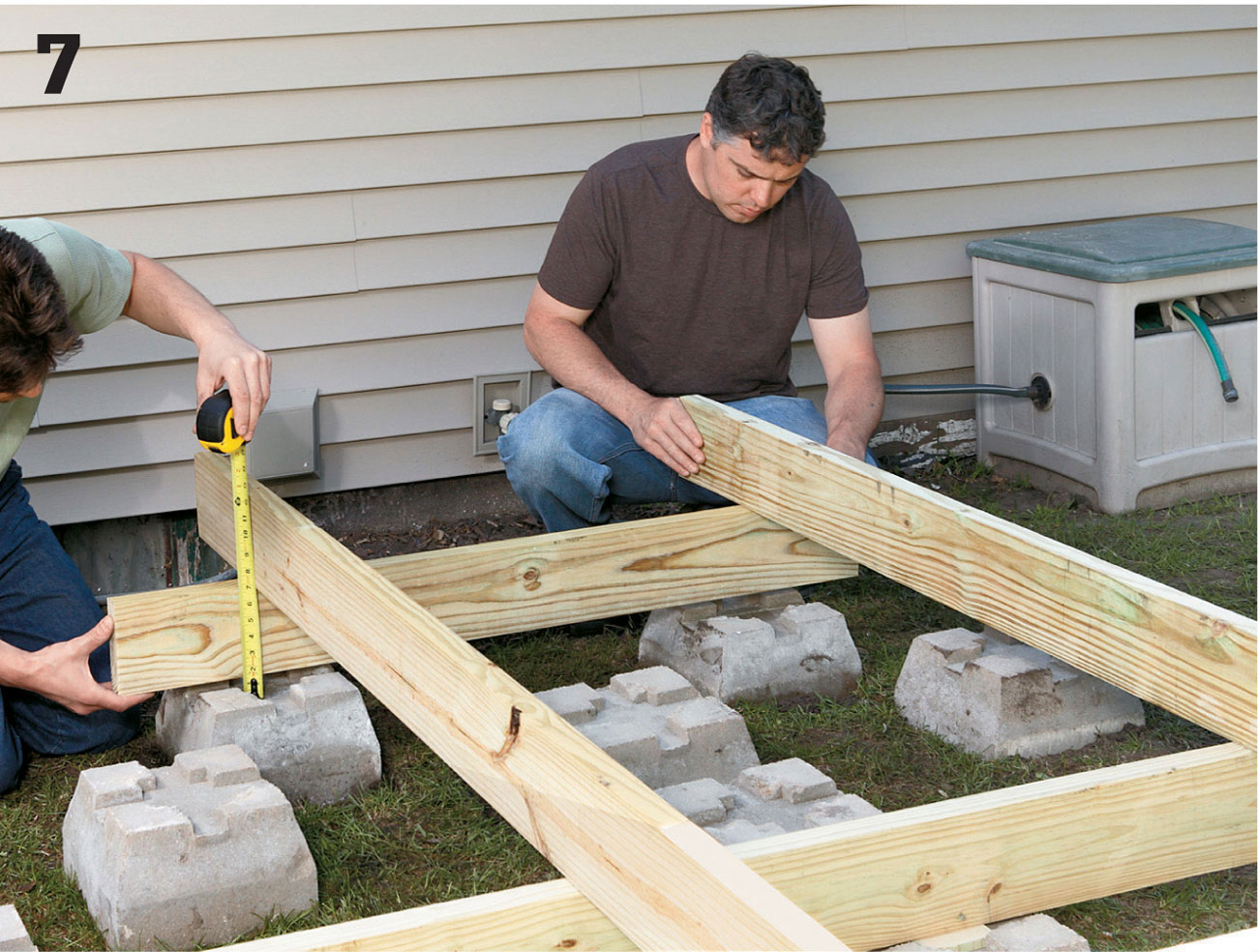
Clear any large rocks or debris from the area over which the deck will be positioned. Measure and mark the locations for the pier blocks. Set out the pier blocks for the center of the deck; you’ll start by building the center “box” rectangle off of which all the other joists will be leveled.
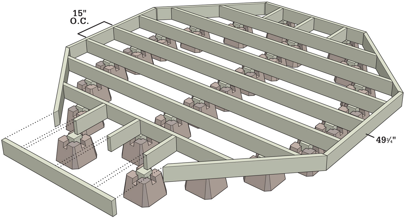
Position three rows of three blocks each. The rows for this deck were placed 46-1/2" OC row to row, with 1 1/2" OC between the pier blocks in each row. Check that each pier block is level, adding or removing dirt underneath to level it as necessary.
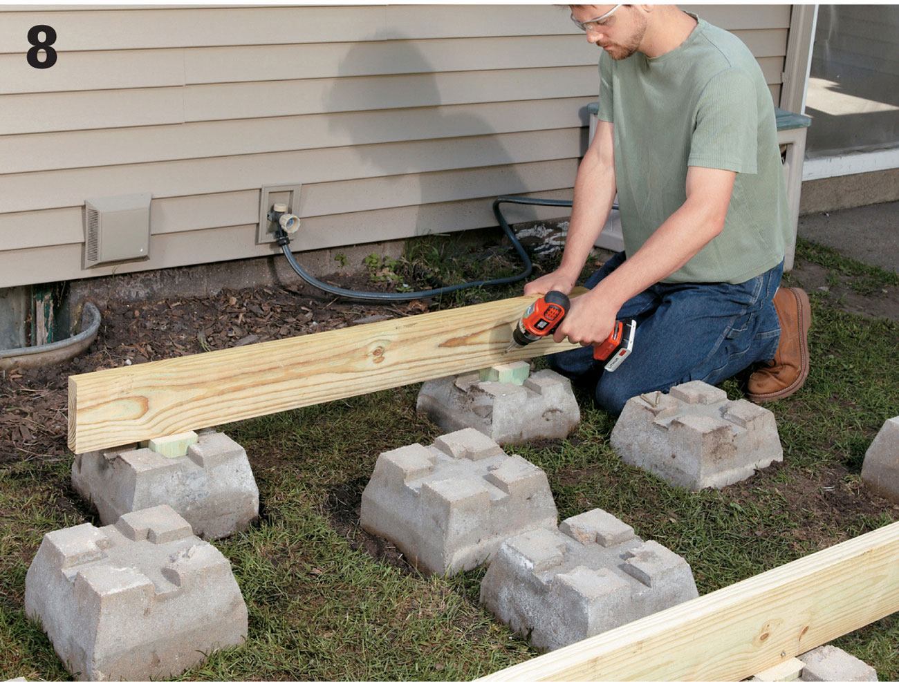
Set a 10-ft. long 2 × 6 joist on edge in the slots of the three pier blocks along one end of each row. Hold a carpenter’s level along the top of the joist as a helper raises or lowers the lowest end of the joist.
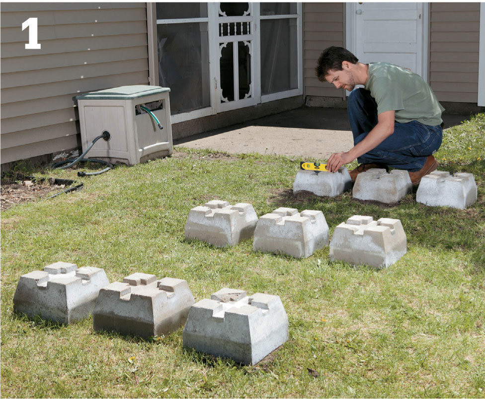
Position the piers accurately to ensure a stable deck. They need to be the proper distance from each other and level side to side.
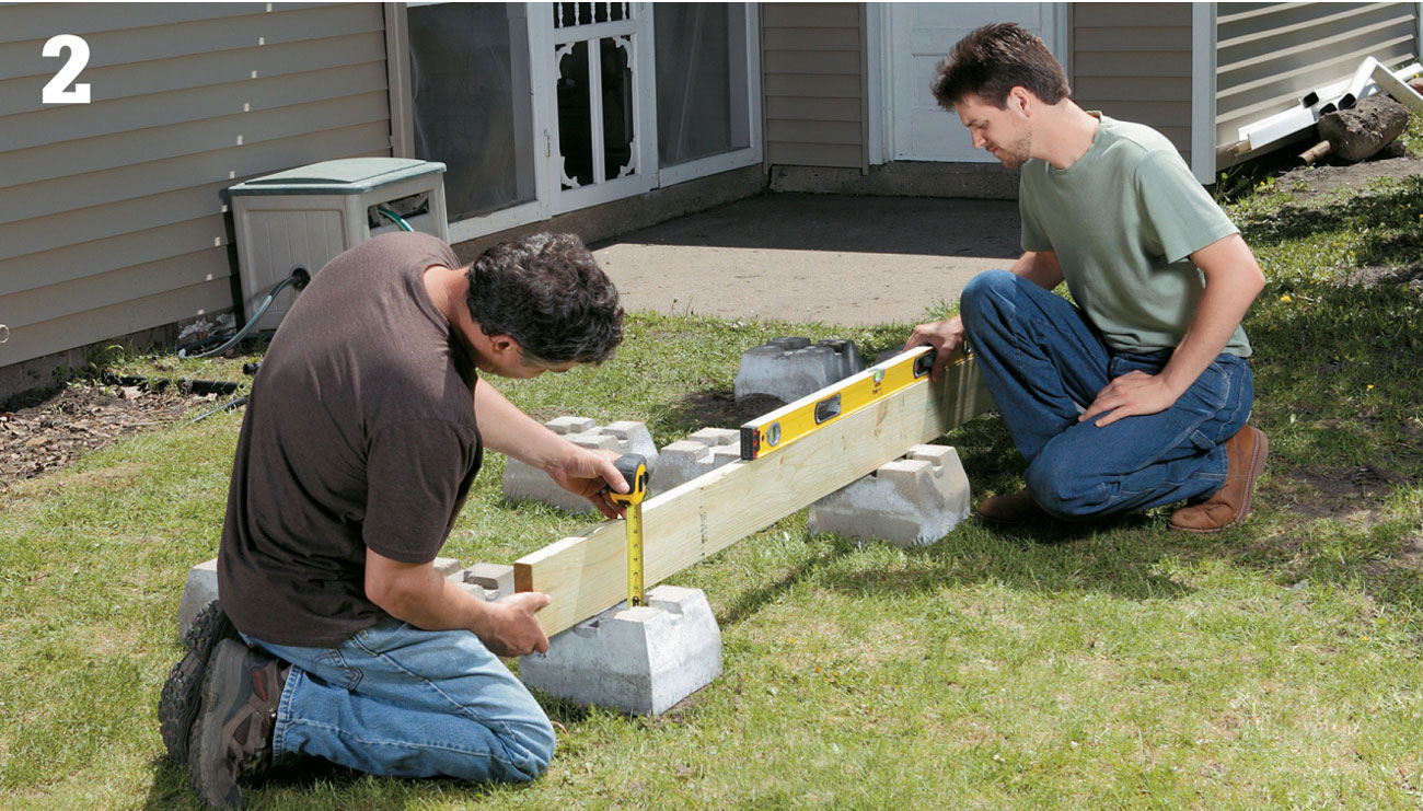
Leveling a joist is a job that calls for a helper. You’ll need to focus on the precise measurements for the posts, if any.
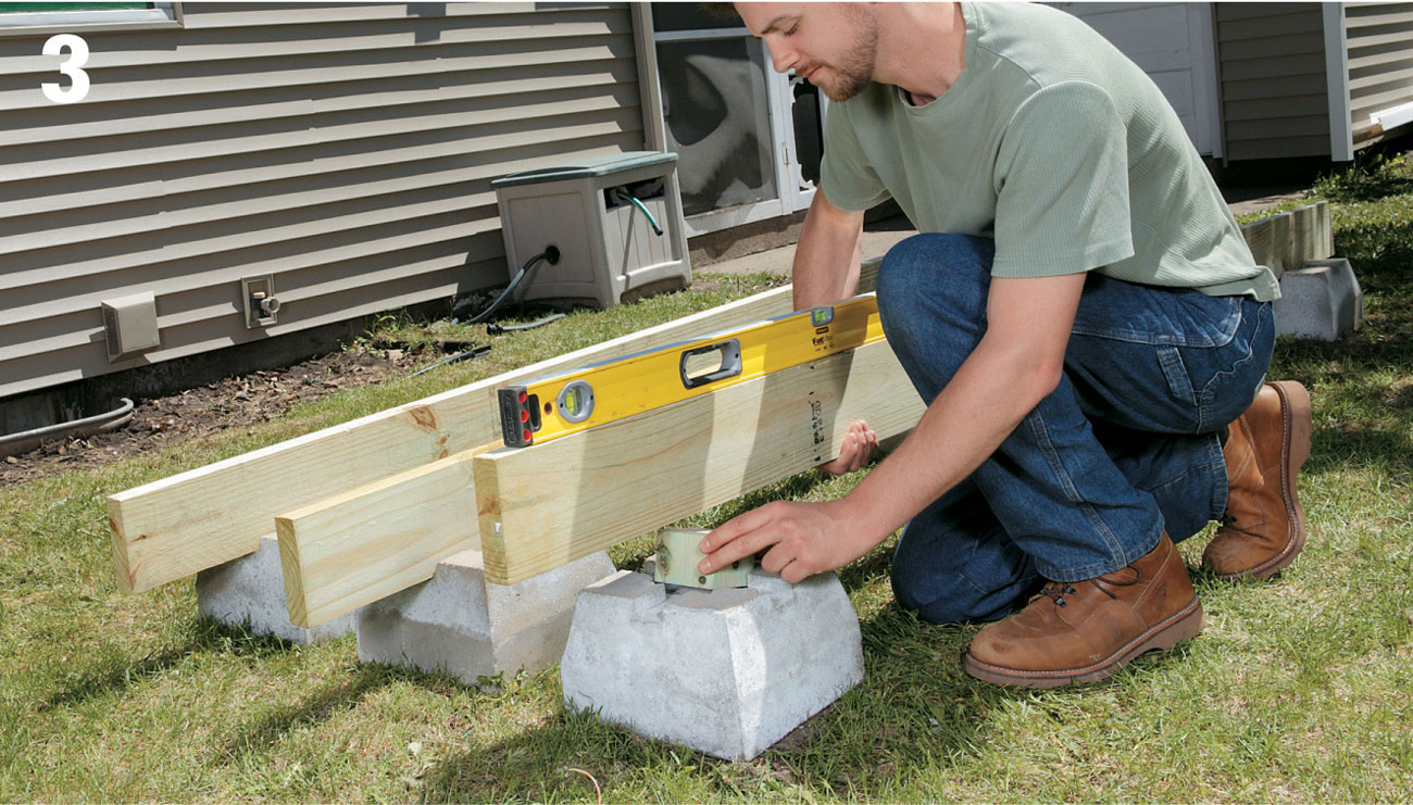
Once the posts are cut, it’s important to check the joists for level in place. Only screw the joists down when the preliminary “box” for the frame is complete. With the helper holding the joist level, measure any gaps between the bottom of the joist and the pier block sockets.
Cut 4 × 4 posts to match the gap measurements, and place the posts in the pier block sockets. Set the 2 × 6 joist on top of the posts, if any, and check for level again. Adjust as necessary.
Repeat the process with a joist set in the sockets of the outside blocks on the other end of each row. Position the joist as before, and check level with the aid of a helper. Once you’ve established level along the length of the second joist, make sure the joists are level side to side.
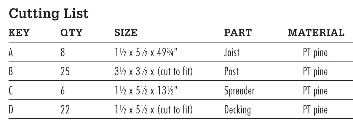
Now cut 2 × 6 band joists for the ends of the floor joists. The band joists will be 49-3/4" long. Measure and mark the band joist so that it will extend equal lengths from both sides of where it is screwed to the floor joists.
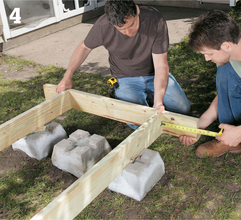
The first two opposite band joists complete the box.
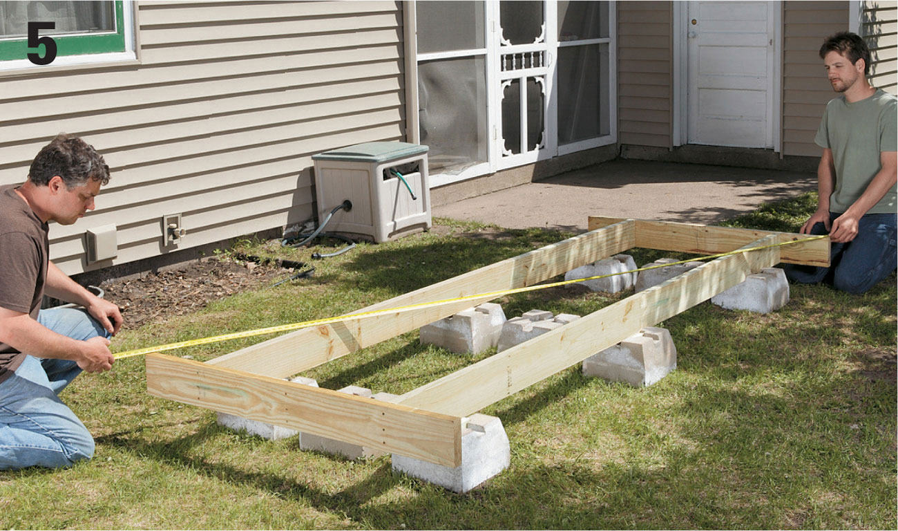
Check diagonal measurements of the foundation center box. This must be square because the rest of the deck is built off the box. If the diagonal measurements are off at all, adjust the “box” until they match.

Complete the center of the deck frame by screwing the center joist into place, attaching it to the band joists on either end.
Use 3" deck screws to screw the band joists to each end of the floor joists to create the center box of the deck floor frame.
Ensure this box is square by measuring diagonally both ways. If the frame is square, the diagonal measurements should be exactly the same.
Position the center joist in this box, cutting 4 × 4 posts as necessary to keep the joist level along its length and in relation to the two outside joists. Screw the band joist into the end of the center floor joist, completing the frame center box. Screw the joists to their 4 × 4 posts in toenail fashion.
Measure and set the remaining pier blocks in place on both sides of the center frame box. There should be a row of three piers and a row of two piers on each side of the center box, as shown in the Framing Plan (page 277).
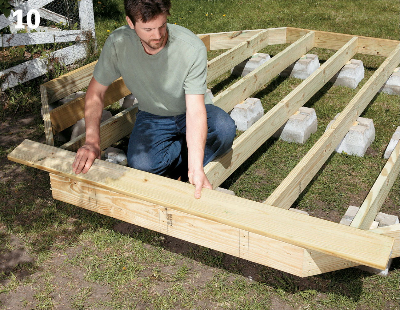
Cut and position the outer floor joists in the octagon, leveling them in place as before.
Install the blocking to support the side piers. Once level, screw the outside joist to the 4 × 4 posts (if any) with the joist positioned so that the overhang on both sides is equal.
Drive 3" screws through the mitered ends to secure the band joists to one another. Use three screws per connection. Complete the outside frame by screwing diagonal band joists onto the mitered ends of the middle floor joists, and to the band joists.
Install the decking boards, allowing for overhang that will be trimmed at the end of construction.
Cut the shorter outside floor joists to length. Set them in place in the outside piers, and measure and level as before. Cut 4 × 4s as necessary, and set the outside joists in position. Miter the two outside joist ends 22-1/2°. Screw all joists to the posts in toenail fashion.
Complete the outside frame by cutting the remaining six band joists. Miter the ends of the four diagonal band joists 22-1/2° before installing them. Drill pilot holes and screw the band joists to the spacer blocks using 3" deck screws. Install the remaining joists. At each end, the band joists will extend beyond the outside row of pier blocks so no blocks will be visibly exposed at the edge of the deck.
Begin laying the decking at one edge of the octagon, so that the decking lays perpendicular to the floor joists. Place the first deck board into position with its edge aligned with the edge of the band joist. Screw down each decking board using two 3" deck screws per joist.
Continue laying the decking, allowing the boards to overhang the edges of the band joists. Maintain a 1/8" gap between boards.
When all the decking boards have been screwed down, snap a chalk line along the edges over which the deck boards hang; use a circular saw equipped with a carbide blade to cut the deck board ends so that the decking is flush with the band joists.
Stain, paint, or finish the deck as you prefer, including the rim joists. Add other built-on structures to suit your needs.
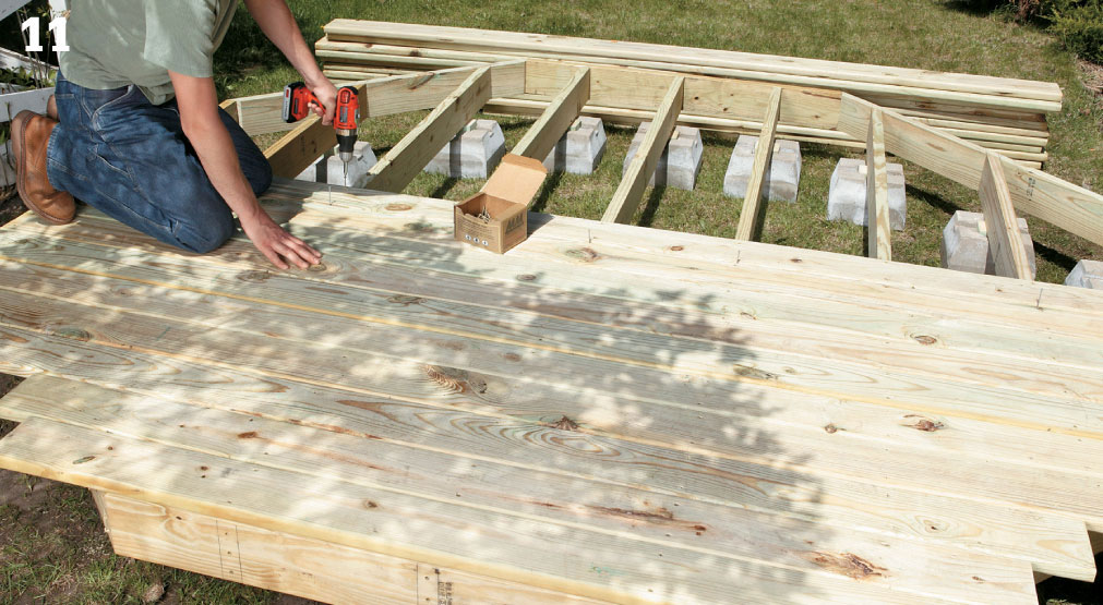
Lay the rest of the decking boards by screwing them down to the joists, maintaining a 1/8" spacing between boards.
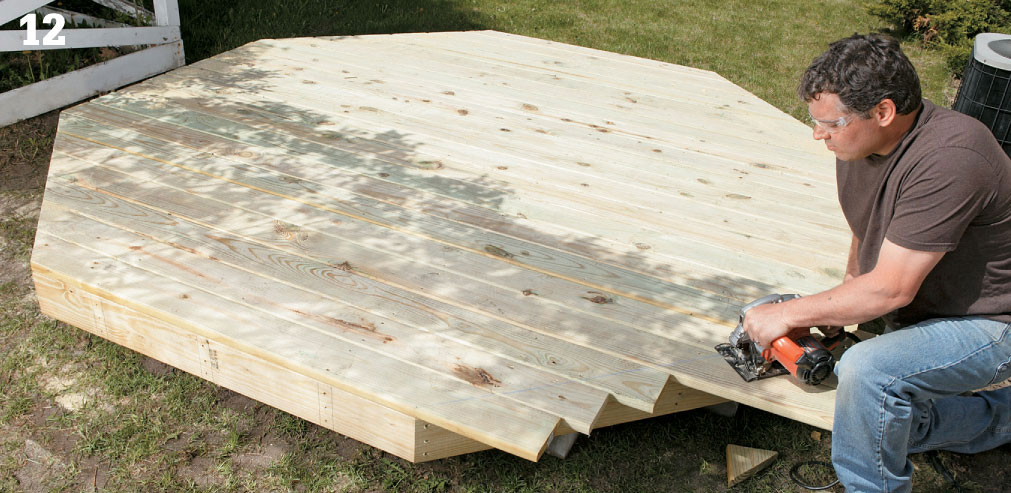
Use a circular saw equipped with a carbide blade to make quick work of trimming the ends of the deck boards, leaving a clean edge.
 Ground Level Walkout Deck
Sometimes less really is more. This modest deck has a pleasing shape and is perched high enough to provide a clear view of the yard. Even better, the deck is a study in simplicity and it won’t cost you a lot in either time or money. The framing and decking plans are straightforward and uncomplicated. You can likely build the entire structure over the course of two or three weekends, even if you have limited carpentry and building experience. That means that before a month is out, you’ll have access to a convenient outdoor platform that can be used for a relaxing meal surrounded by nature, a place to read the paper, or to just sit and recharge your batteries after a long day at work.
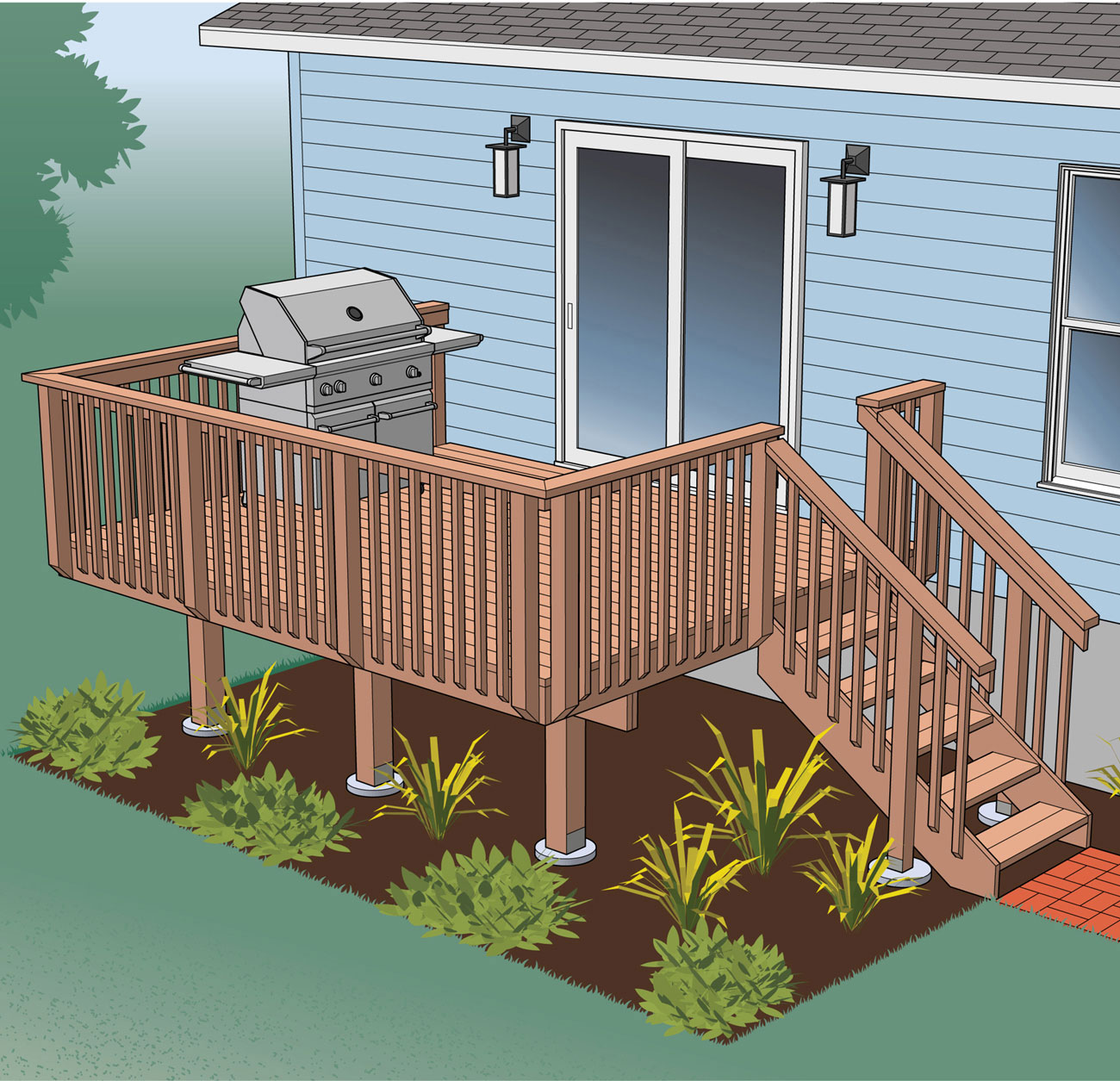
This basic rectangular platform is as plainly handsome as it is useful and easy to build.
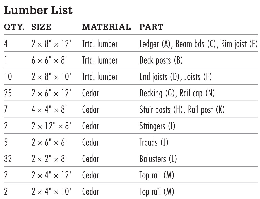
Supplies
10"-diameter footing forms (3)
8"-diameter footing forms (2)
J-bolts (5)
6 × 6" metal post anchors (3)
4 × 4" metal post anchors (2)
6 × 6" metal post-beam caps (3)
2 × 8" joist hangers (16)
1 1/2 × 6" angle brackets (6)
1 1/2 × 10" angle brackets (10)
3" galvanized deck screws
16d galvanized nails
2-1/2" galvanized deck screws
3/8 × 4" lag screws and washers (20)
3/8 × 5" lag screws and washers (22)
1/4 × 1 1/4" lag screws and washers (80)
Flashing (12 ft.)
Exterior silicone caulk (3 tubes)
Concrete as needed
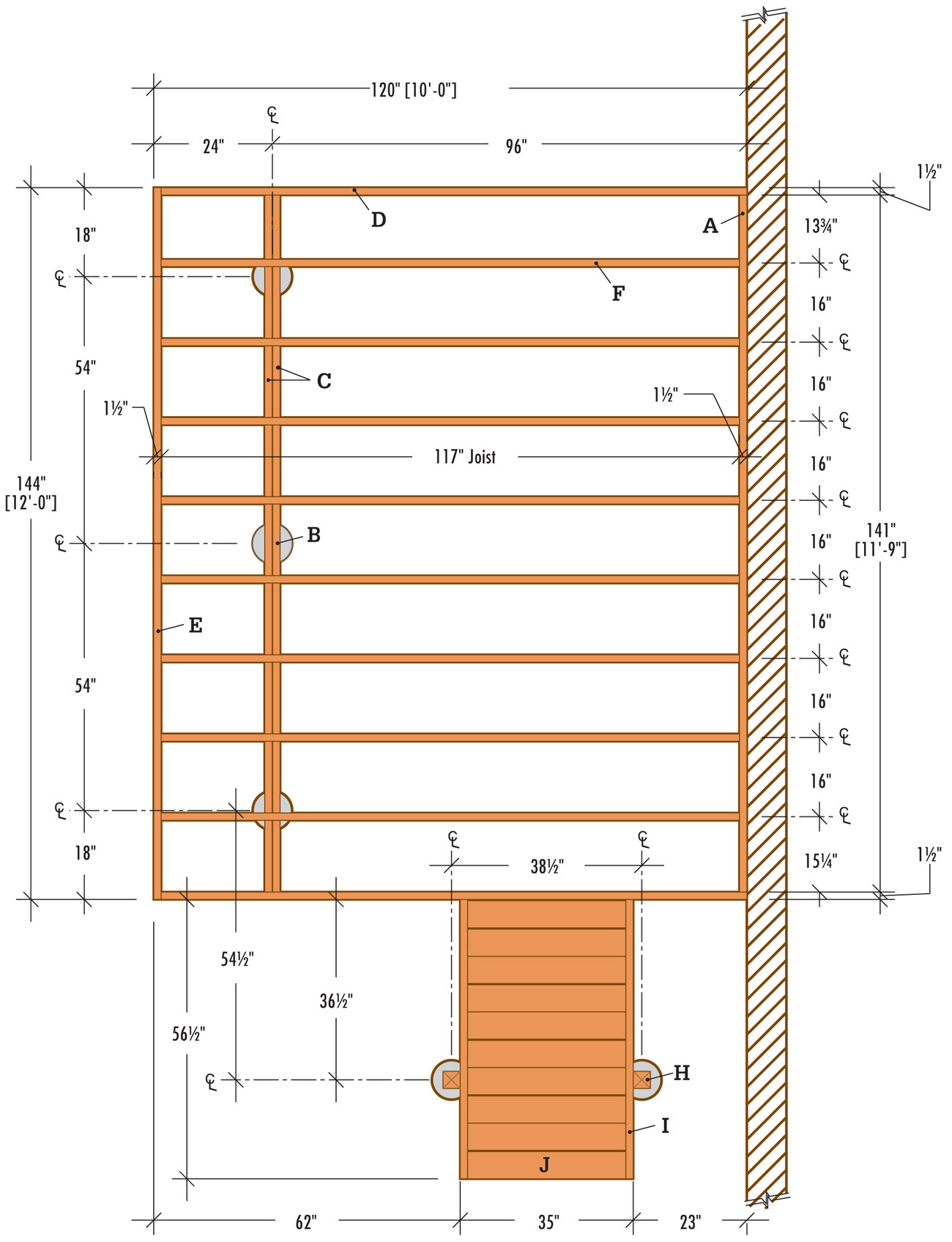
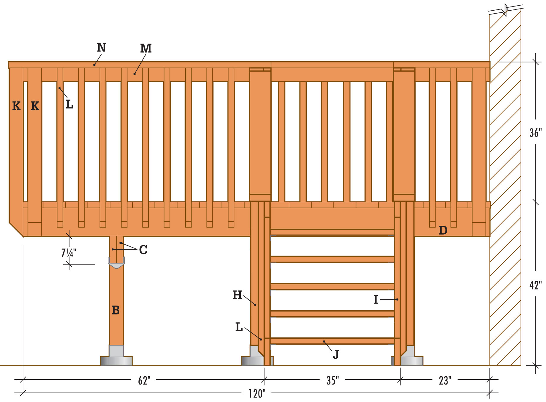
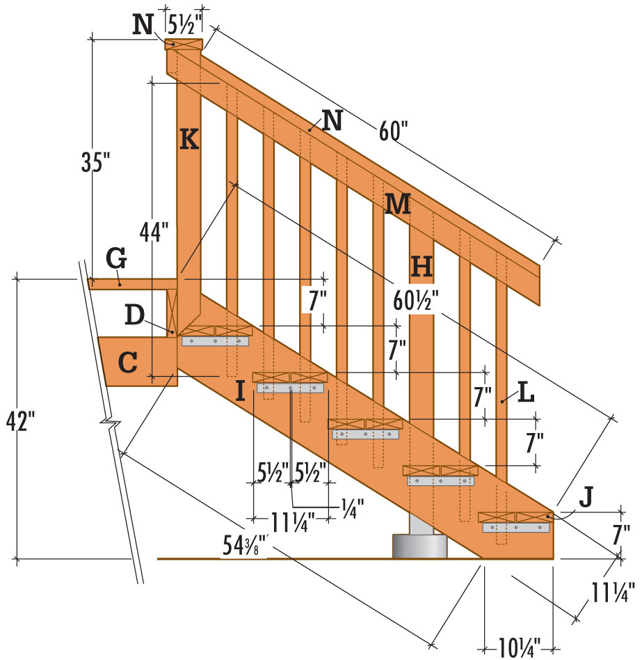
Stairway Detail
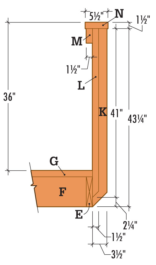
Railing Detail
 How to Build a Ground-level Walkout Deck
Draw a level outline on the siding to show where the ledger and the end joists will fit against the house. Install the ledger so that the surface of the decking boards will be 1" below the indoor floor level. This height difference prevents rainwater or melted snow from seeping into the house.
Cut out the siding along the outline with a circular saw. To prevent the blade from cutting the sheathing that lies underneath the siding, set the blade depth to the same thickness as the siding. Finish the cutout with a chisel, holding the beveled side in to ensure a straight cut.
Cut galvanized flashing to the length of the cutout, using metal snips. Slide the flashing up under the siding at the top of the cutout.
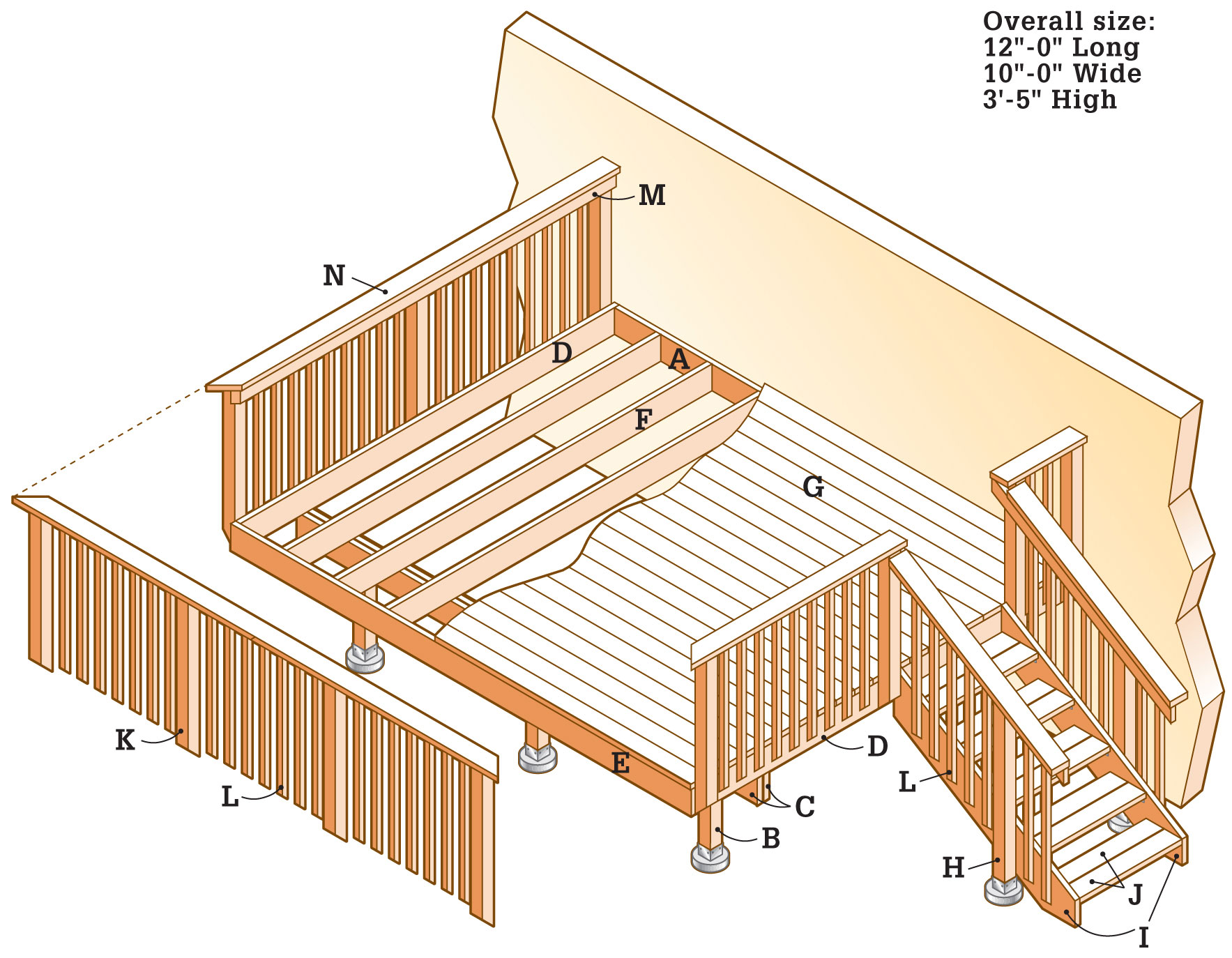
Measure and cut the ledger (A) from pressure-treated lumber. Center the ledger end to end in the cutout, with space at each end for the end joist.
Brace the ledger in position under the flashing. Tack the ledger into place with galvanized deck screws.
Drill pairs of 3/8" pilot holes at 16" intervals through the ledger and into the house header joist. Counterbore each pilot hole 1/2", using a 1 3/8" spade bit. Attach the ledger to the wall with 3/8 × 4" lag screws and washers, using a ratchet wrench.
Apply a thick bead of silicone caulk between siding and flashing. Also seal the lag screw heads and the cracks at the ends of the ledger.
Referring to the measurements shown in the Framing Plan (page 284), mark the centerlines of the two outer footings on the ledger and drive nails at these locations.
Set up temporary batterboards and stretch a mason’s string out from the ledger at each location. Make sure the strings are perpendicular to the ledger, and measure along the strings to find the centerpoints of the posts.
Set up additional batterboards and stretch another string parallel to the ledger across the post centerpoints.
Check the mason’s strings for square by measuring diagonally from corner to corner and adjusting the strings so that the measurements are equal.
Measure along the cross string and mark the center post location with a piece of tape.
Use a plumb bob to transfer the footing centerpoints to the ground, and drive a stake to mark each point.
Remove the mason’s strings and dig the post footings, using a clamshell digger or power auger. Pour 2" to 3" of loose gravel into each hole for drainage. Note: When measuring the footing size and depth, make sure you comply with your local building code, which may require flaring the base.
Cut the footing forms to length using a reciprocating saw or handsaw, and insert them into the footing holes, leaving 2" above ground level. Pack soil around the forms for support, and fill the forms with concrete, tamping with a long stick or rod to eliminate any air pockets.
Screed the tops flush with a straight 2 × 4. Insert a J-bolt into each footing, set so 3/4" to 1" of thread is exposed. Retie the mason’s strings and position the J-bolts at the exact center of the posts, using a plumb bob as a guide. Clean the bolt threads before concrete sets.
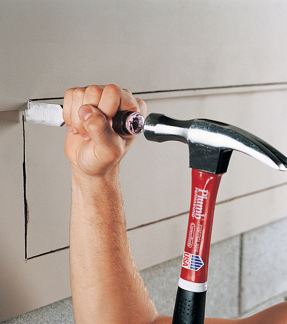
After outlining the position of the ledger and cutting the siding with a circular saw, use a chisel to finish the corners of the cutout.
After the posts have been set in place and braced plumb, use a straight 2 × 4 and a level to mark the top of the beam on each post.
Lay a long, straight 2 × 4 flat across the footings, parallel to the ledger. With one edge tight against the J-bolts, draw a reference line across each footing.
Place a metal post anchor on each footing, centering it over the J-bolt and squaring it with the reference line. Attach the post anchors by threading a nut over each bolt and tightening with a ratchet wrench.
Cut the posts to length, adding approximately 6" for final trimming. Place the posts in the anchors and tack into place with one nail.
With a level as a guide, use braces and stakes to plumb the posts. Finish nailing the posts to the anchors.
Determine the height of the beam by extending a straight 2 × 4 from the top edge of the ledger across the face of a post. Level the 2 × 4, and draw a line on the post along the bottom of the 2 × 4.
From that line, measure 15 1/2" down the post and mark the bottom of the beam. Using a level, transfer this line to the remaining posts.
Use a combination square to extend the level line completely around each post. Cut the posts to this finished height using a circular saw and reciprocating saw.
Cut the beam boards (C) several inches longer than necessary, to allow for final trimming.
Join the beam boards together with 2-1/2" galvanized deck screws. Mark the post locations on the top edges and sides, using a combination square as a guide.
Attach the post-beam caps to the tops of the posts. Position the caps on the post tops, and attach using 10d joist hanger nails.
Lift the beam into the post-beam caps, with the crown up. Align the post reference lines on the beam with the post-beam caps. Note: You should have at least two helpers when installing boards of this size and length, at this height.
Fasten the post-beam caps to the beam on both sides using 10d joist hanger nails.
Measure and cut the end joists to length using a circular saw.
Attach end joists to the ends of the ledger with 10d common nails.
Measure and cut the rim joist (E) to length with a circular saw. Fasten to end joists with 16d galvanized nails.
Square up the frame by measuring corner to corner and adjusting until measurements are equal. Toenail the end joists in place on top of the beam, and trim the beam to length.
Reinforce each inside corner of the frame with an angle bracket fastened with 10d joist hanger nails.
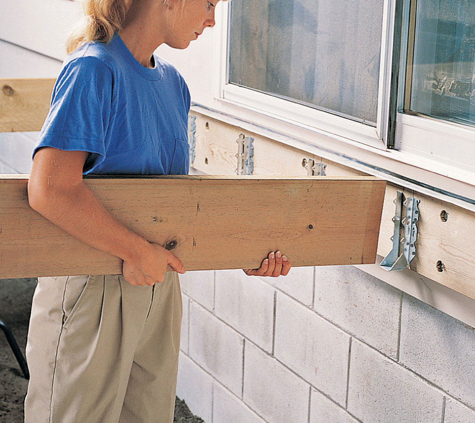
Install joists in hangers with crown edge up.
To locate the stairway footings, refer to the measurements in the Framing Plan, and extend a straight 2 × 4 perpendicularly from the deck. Use a plumb bob to transfer centerpoints to the ground.
Mark the outlines of the inner joists (F) on the ledger, beam, and rim joist (see Framing Plan, page 284), using a tape measure and a combination square.
Attach joist hangers to the ledger and rim joist with 10d joist hanger nails, using a scrap 2 × 8 as a spacer to achieve the correct spread for each hanger.
Measure, mark, and cut lumber for inner joists using a circular saw. Place the joists in the hangers with crown side up, and attach at both ends with 10d joist hanger nails. Be sure to use all the holes in the hangers.
Align the joists with the marks on top of the beam, and toenail or strap in place.
Cut the first decking board (G) to length, position it against the house, and attach by driving a pair of 2-1/2" galvanized deck screws into each joist.
Position the remaining decking boards with the ends overhanging the end joists. Leave a 1/8" gap between boards to provide for drainage, and attach the boards to each joist with a pair of deck screws.
Every few rows of decking, measure from the edge of the decking to the outside edge of the deck. If the measurement can be divided evenly by 5-5/8, the last board will fit flush with the outside edge of the deck as intended. If the measurement shows that the last board will not fit flush, adjust the spacing as you install the remaining rows of boards.
If your decking overhangs the end joists, snap a chalk line to mark the outside edge of the deck and cut flush with a circular saw. If needed, finish the cut with a jigsaw or handsaw where a circular saw can’t reach.
Refer to the Framing Plan (page 284), for the position of the stairway footings.
Locate the footings by extending a 2 × 4 from the deck, dropping a plumb bob, and marking the centerpoints with stakes.
Dig post holes with a clamshell digger or an auger, and pour the stairway footings using the same method as for the deck footings.
Attach metal post anchors to the footings, and install posts (H), leaving them long for final trimming.
Cut the stair stringers (I) to length and use a framing square to mark the rise and run for each step (see Stairway Detail, page 285). Draw the tread outline on each run. Cut the angles at the end of the stringers with a circular saw. (For more information on building stairways, see pages 140 to 159.)
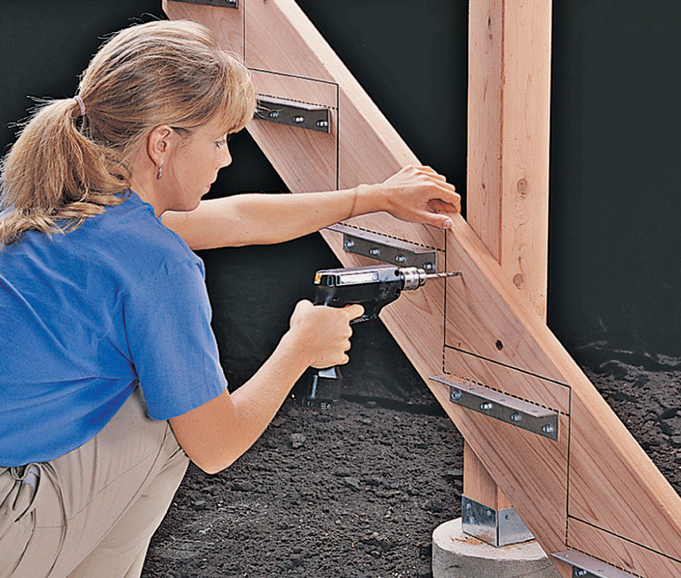
After attaching the stringers to the deck, fasten them to the posts. Drill and counterbore two pilot holes through the stringers into the posts, and attach with lag screws.
Position a 1 1/2 × 10" angle bracket flush with the bottom of each tread line. Attach the brackets with 1 1/4" lag screws.
Fasten angle brackets to the upper ends of the stringers, using 1 1/4" lag screws; keep the brackets flush with cut ends on stringers. Position the top ends of the stringers on the side of the deck, making sure the top point of the stringer and the surface of the deck are flush.
Attach the stringers by driving 10d joist hanger nails through the angle brackets into the end joist, and by drilling 1/4" pilot holes from inside the rim joist into the stringers and fastening with 3/8 × 4" lag screws.
To connect the stringers to the stair posts, drill two 1/4" pilot holes and counterbore the pilot holes 1/2" deep with a 1" spade bit. Use a ratchet wrench to fasten the stringers to the posts with 4" lag screws and washers.
Measure the length of the stair treads (J) and cut two 2 × 6 boards for each tread. For each tread, position the front board on the angle bracket so the front edge is flush with the tread outline on the stringers. Attach the tread to the brackets with 1/4 × 1 1/4" lag screws.
Place the rear 2 × 6 on each tread bracket, keeping a 1/8" space between the boards. Attach with 1 1/4" lag screws.
Attach the treads for the lowest step by driving deck screws through the stringers.
Cut posts (K) and balusters (L) to length (see Railing Detail, page 285) with a power miter saw or circular saw. Cut the top ends square, and the bottom ends at a 45° angle.
Mark and drill two 3/8" pilot holes at the bottom end of each post. Holes should be spaced 4" apart and counterbored 1/2", with a 1" spade bit.
Drill two 1/8" pilot holes, 4" apart, near the bottom of each baluster. At the top of each baluster, drill a pair of 1/8" pilot holes spaced 1 1/2" apart.
Using a combination square, mark the locations of the posts on the outside of the deck. Note: Position corner posts so there is no more than 4" clearance between them.
Clamp each post in place. Keep the beveled end flush with the bottom of the deck, and make sure the post is plumb. Use an awl to mark pilot hole locations on the side of the deck. Remove posts and drill 3/8" pilot holes at marks. Attach the railing posts to the side of the deck with 1/2 × 5" lag screws and washers.
Cut top rails (M) to length, with 45° miters on the ends that meet at the corners. Attach to posts with 2-1/2" deck screws, keeping the top edge of the rail flush with the top of the posts. Join rails by cutting 45° bevels at ends.
Temporarily attach stairway top rails with 3" galvanized screws. Mark the outline of the deck railing post and top rail on the back side of the stairway top rail. Mark the position of the top rail on the stairway post. Use a level to mark a plumb cutoff line at the lower end of the rail. Remove the rail.
Cut the stairway post to finished height along the diagonal mark, and cut the stairway rail along outlines. Reposition the stairway rail and attach with deck screws.
Attach the balusters between the railing posts at equal intervals of 4" or less. Use deck screws, and keep the top ends of balusters flush with the top rail. On the stairway, position the balusters against the stringer and top rail, and check for plumb. Draw a diagonal cut line at top of baluster and trim to final height with a power miter saw.
Confirm measurements, and cut rail cap sections (N) to length. Position sections so that the inside edge overhangs the inside edge of the rail by 1/4". Attach the cap to the rail with deck screws. At corners, miter the ends 45° and attach caps to posts.
Cut the cap for stairway rail to length. Mark angle of deck railing post on side of cap and bevel-cut the ends of the cap. Attach cap to top rail and post with deck screws. Note: Local building codes may require a grippable handrail. Check with your building inspector.
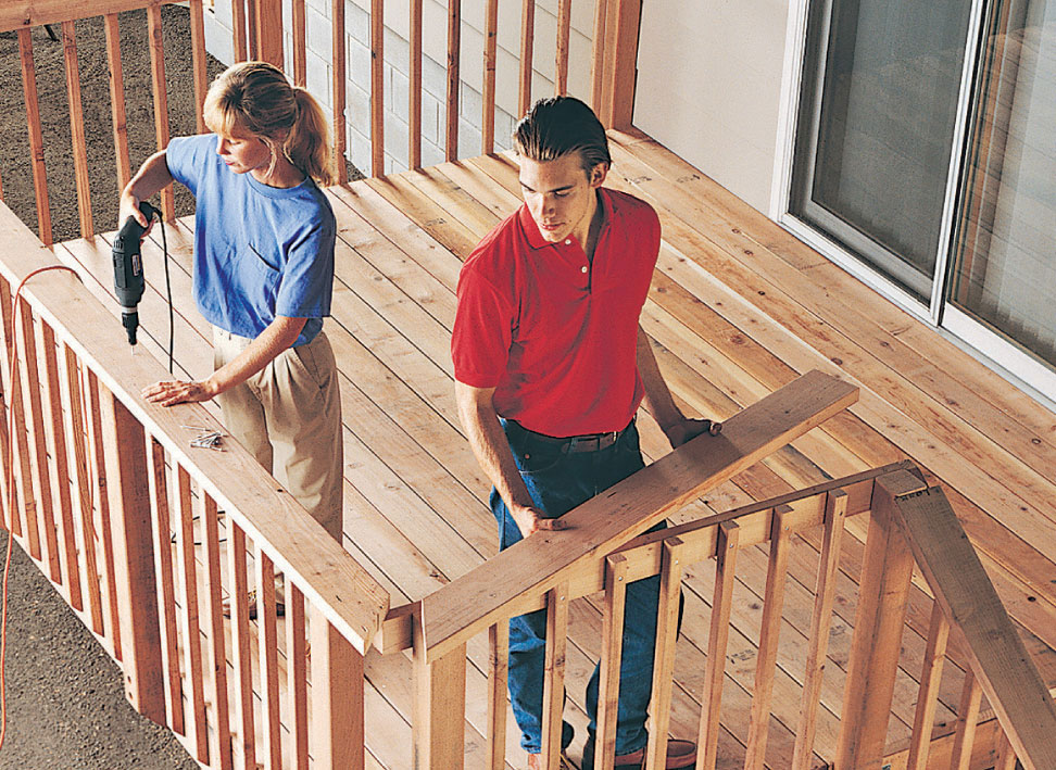
Position the rail cap over the posts and balusters. Make sure mitered corners are tight, and attach with deck screws.
 Second-story Walkout Deck
This simple rectangular deck provides a secure, convenient outdoor living space. The absence of a stairway prevents children from wandering away or unexpected visitors from wandering in. It also makes the deck easier to build.
Imagine how handy it will be to have this additional living area only a step away from your dining room or living room, with no more need to walk downstairs for outdoor entertaining, dining, or relaxing.
And if you’d like to add a stairway, just refer to the chapter on stair-building (see page 140).
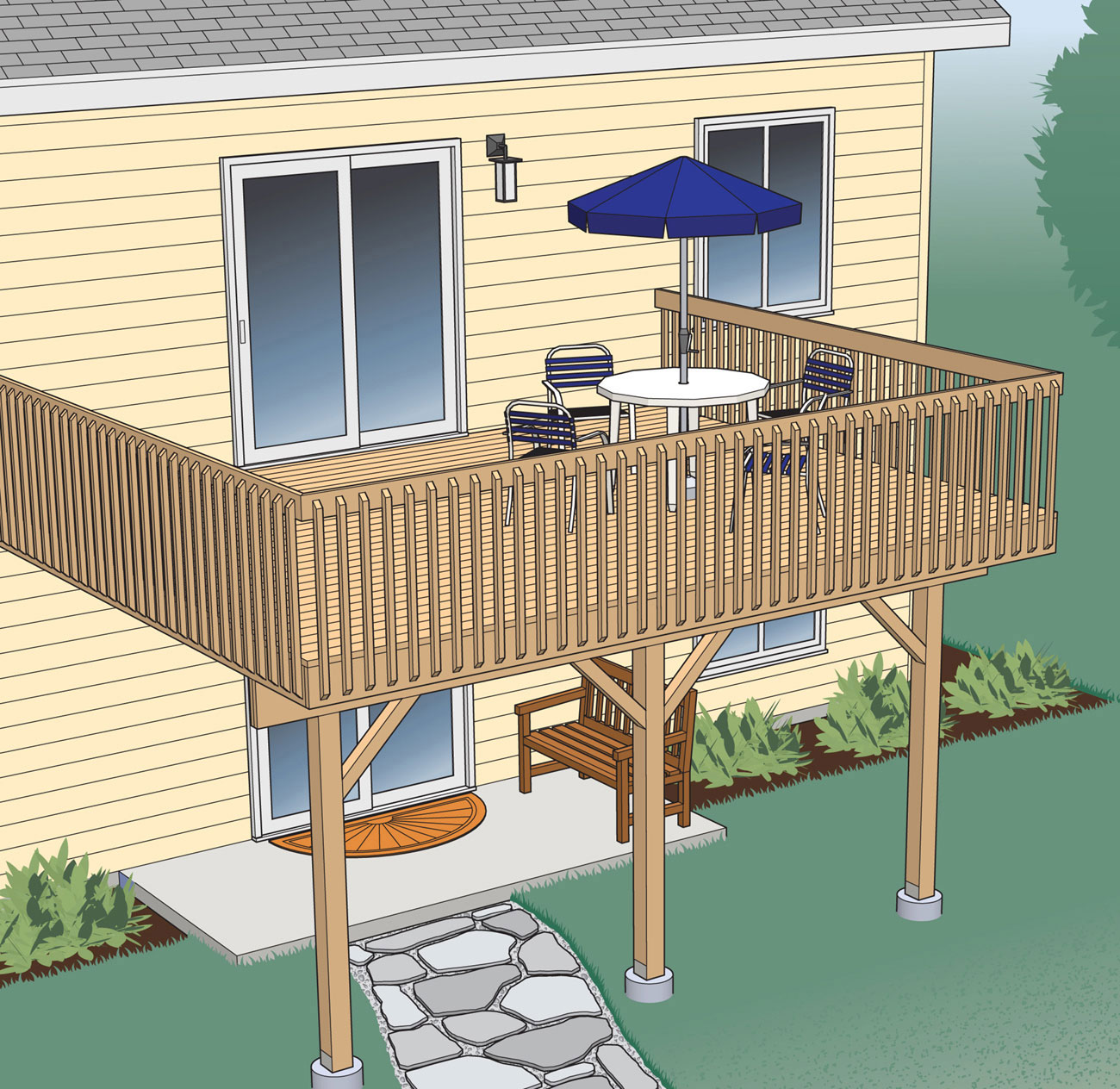
Simplicity, security, and convenience are the hallmarks of this elevated deck.
Supplies
12"-diameter footing forms (3)
J-bolts (3)
6 × 6" metal post anchors (3)
2 × 10" joist hangers (26)
Galvanized deck screws (3", 2-1/2", and 1 1/4")
Joist hanger nails
1/2 × 4" lag screws and washers (28)
1/2 × 5" lag screws and washers (16)
1/2 × 7" carriage bolts, washers, and nuts (6)
16d galvanized nails
Metal flashing (18 ft.)
Silicone caulk (3 tubes)
Concrete as required
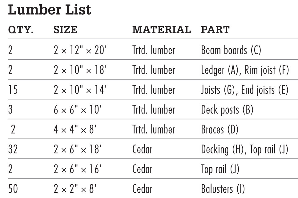
Railing Detail
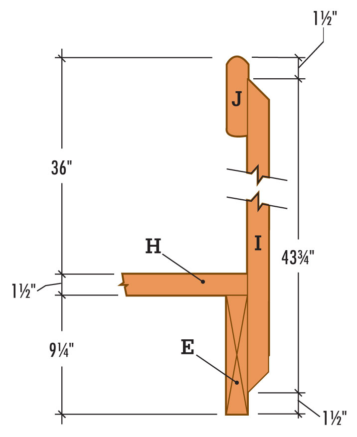
Face Board Detail
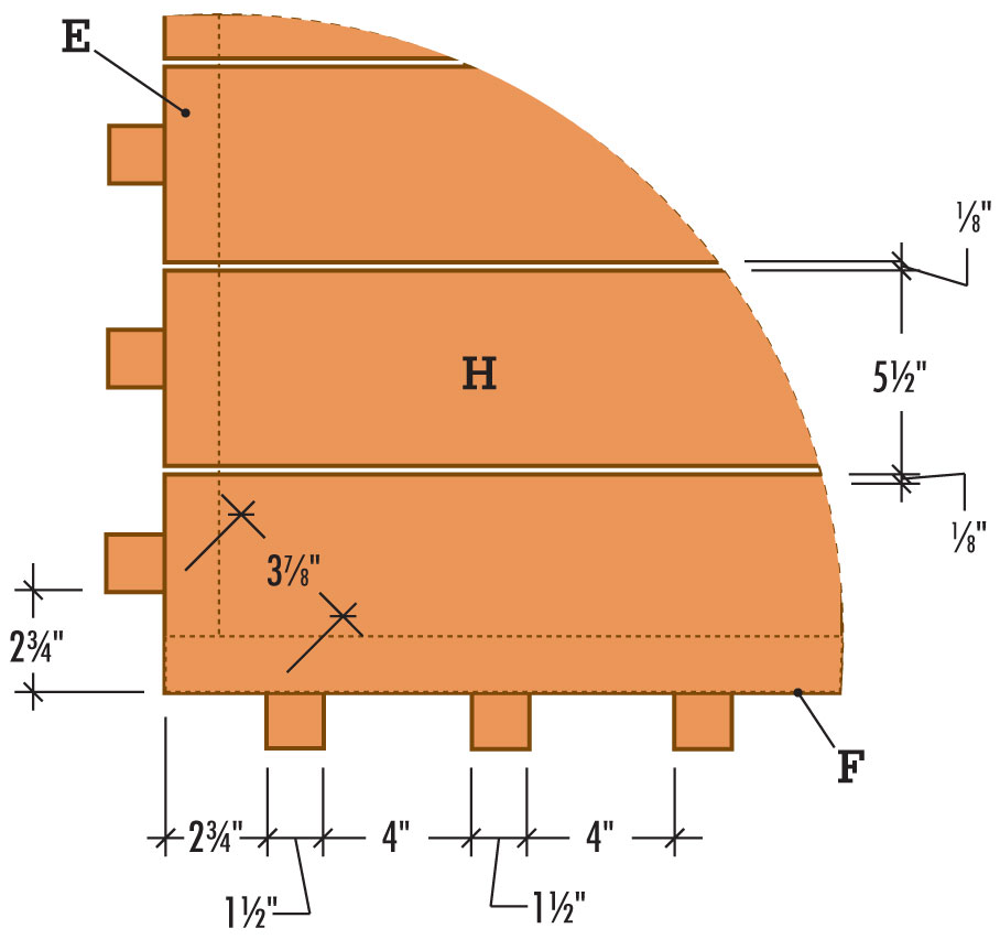
 How to Build a Second-story Walkout Deck
Draw a level outline on the siding to show where the ledger and the end joists will fit against the house. Install the ledger so that the surface of the decking boards will be 1" below the indoor floor level. This height difference prevents rainwater or melted snow from seeping into the house.
Cut out the siding along the outline with a circular saw. To avoid cutting the sheathing that lies underneath the siding, set the blade depth to the same thickness as the siding. Finish the cutout with a chisel, holding the beveled side in to ensure a straight cut.
Cut galvanized flashing to the length of the cutout, using metal snips. Slide the flashing up under the siding at the top of the cutout.
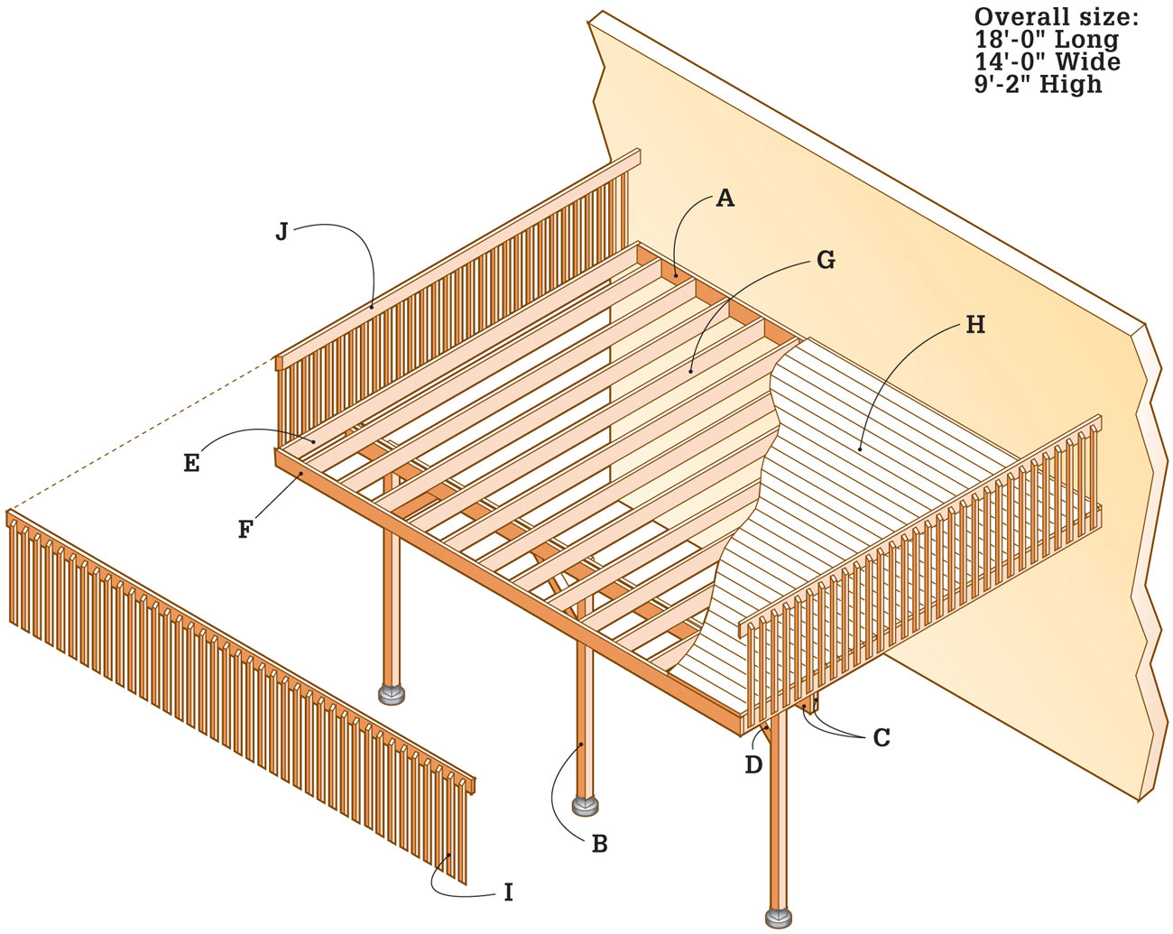
Measure and cut the ledger (A) from pressure-treated lumber. Center the ledger end to end in the cutout, with space at each end for the end joists.
Brace the ledger into position under the flashing. Tack the ledger into place with galvanized nails.
Drill pairs of 3/8" pilot holes at 16" intervals through the ledger and into the house header joist. Counterbore each pilot hole 1/2", using a 1 3/8" spade bit. Attach the ledger with 4" lag screws and washers using a ratchet wrench.
Apply silicone caulk between the siding and flashing. Also seal the lag screw heads and the cracks at the ends of the ledger.
To establish a reference point for locating the footings, drop a plumb bob from the ends of the ledger down to the ground.
Position a straight 14 ft.-long 2 × 4 perpendicular to the house at the point where the plumb bob meets the ground. Note: If you are building on a steep slope or uneven ground, the mason’s string method of locating footing positions will work better (see pages 70 to 75).
Check for square, using the 3-4-5 triangle method. From the 2 × 4, measure 3 ft. along the wall and make a mark. Next, measure 4 ft. out from the house and make a mark on the 2 × 4. The diagonal line between the marks will measure 5 ft. when the board is accurately square to the house. Adjust the board as needed, using stakes to hold it in place.
Extend another reference board from the house at the other end of the ledger, following the same procedure.
Measure out along both boards, and mark the centerline of the footings (see Framing Plan, page 292).
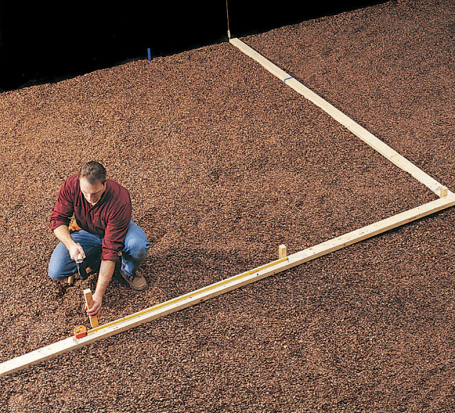
Use a template made from 2 × 4s to locate the post footings on the ground, then mark the footings with stakes.
Plumb each post with a level, then use braces and stakes to hold the post in place until the beam and joists are installed.
Lay a straight 2 × 4 between the centerline marks, and drive stakes to mark the footing locations.
Remove the boards and dig the post footings, using a clamshell digger or power auger. Pour 2" to 3" of loose gravel into each hole for drainage. Note: When measuring the footing size and depth, make sure you comply with local building codes, which may require flaring the base to 18".
Cut the footing forms to length, using a reciprocating saw or handsaw, and insert them into the footing holes, leaving 2" above ground level. Pack soil around the forms for support, and fill the forms with concrete, tamping with a long stick or rod to eliminate any air gaps.
Screed the tops flush with a straight 2 × 4. Insert a J-bolt into the center of each footing and set with 3/4" to 1" of thread exposed. Clean the bolt threads before the concrete sets.
Lay a long, straight 2 × 4 flat across the footings, parallel to the house. With one edge tight against the J-bolts, draw a reference line across the top of each footing to help orient the post anchors.
Place a metal post anchor on each footing, centering it over the J-bolt and squaring it with the reference line. Attach the post anchors by threading a nut over each bolt and tightening with a ratchet wrench.
The tops of the posts (B) will eventually be level with the bottom edge of the ledger, but initially cut the posts several inches longer to allow for final trimming. Position the posts in the anchors and tack into place with one nail each.
With a level as a guide, use braces and stakes to ensure that the posts are plumb.
Determine the height of the beam by using a chalk line and a line level. Extend the chalk line out from the bottom edge of the ledger, make sure that the line is level, and snap a mark across the face of a post. Use the line and level to transfer the mark to the remaining posts.
Remove the posts from the post anchors and cut to the finished height.
Measure and mark a 3 × 11 1/4" notch at the top of each post, on the outside face. Use a framing square to trace lines on all sides. Rough-cut the notches with a circular saw, then finish with a reciprocating saw or handsaw.
Reattach the posts to the post anchors, with the notch-side facing away from the deck.
Cut the beam boards (C) to length, adding several inches to each end for final trimming after the deck frame is squared up.
Join the beam boards together with 2-1/2" galvanized deck screws. Mark the post locations on the top edges and sides, using a combination square as a guide.
Lift the beam, one end at a time, into the notches with the crown up. Align and clamp the beam to the posts. Note: Installing boards of this size and length, at this height, requires caution. You should have at least two helpers.
Thread a carriage bolt into each pilot hole. Add a washer and nut to the end of each bolt and tighten with a ratchet wrench. Seal both ends of the bolts with silicone caulk.
Cut the tops of the posts flush with the top edge of the beam using a circular saw and reciprocating saw.
Measure and cut the end joists (E) to length using a circular saw.
Attach the end joists to the ends of the ledger with 16d galvanized nails.
Measure and cut the rim joist (F) to length with a circular saw. Fasten it to the ends of the end joists with 16d nails.
Square up the frame by measuring corner to corner and adjusting until the measurements are equal. When the frame is square, toenail the end joists in place on top of the beam.
Trim the ends of the beam flush with the faces of the end joists using a reciprocating saw or a handsaw.
Cut the braces (D) to length (see Elevation, page 293) with a circular saw or power miter saw. Miter both ends at 45°.
Install the braces by positioning them against the beam boards and against the posts. Make sure the outside faces of the braces are flush with the outside faces of the beam and the posts. Temporarily fasten with deck screws.
Secure the braces to the posts with 5" lag screws. Drill two 3/8" pilot holes through the upper end of each brace into the beam. Counterbore to a 1/2"-depth using a 1 3/8" spade bit, and drive lag screws with a ratchet wrench. Repeat for the lower end of the braces into the posts.
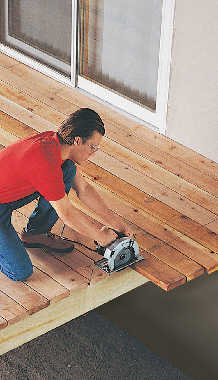
Snap a chalk line flush with the outside edge of the deck, and cut off overhanging deck boards with a circular saw.
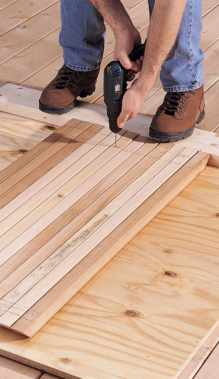
After cutting balusters to length, gang them up and drill 1/8" pilot holes through the top and bottom.
Measure and mark the joist locations (see Framing Plan, page 292) on the ledger, rim joist, and beam. Draw the outline of each joist on the ledger and rim joist, using a combination square.
Install a joist hanger at each joist location. Attach one flange of the hanger to one side of the outline, using joist nails. Use a spacer cut from scrap 2 × 8 lumber to achieve the correct spread for each hanger, then fasten the remaining side flange with joist nails. Remove the spacer and repeat the same procedure for the remaining joist hangers.
Measure, mark, and cut lumber for joists (G) using a circular saw. Place joists in hangers with crown side up and attach with joist hanger nails. Align joists with the outlines on the top of the beam, and toenail in place.
Measure, mark, and cut the decking boards (H) to length as needed.
Position the first row of decking flush against the house, and attach by driving a pair of galvanized deck screws into each joist.
Position the remaining decking boards, leaving a 1/8" gap between boards to provide for drainage, and attach to each joist with deck screws.
Every few rows of decking, measure from the edge of the decking to the outside edge of the deck. If the measurement can be divided evenly by 5-5/8", the last board will fit flush with the outside edge of the deck as intended. If the measurement shows that the last board will not fit flush, adjust the spacing as you install the remaining rows of boards.
If your decking overhangs the end joists, snap a chalk line to mark the outside edge of the deck and cut flush with a circular saw set to a 1 1/2" depth. If needed, finish the cut with a jigsaw or handsaw where a circular saw can’t reach.
Measure, mark, and cut the balusters (I) to length, with 45° miters at both ends.
Gang the balusters together and drill two 1/8" pilot holes at both ends.
Clamp a 1 1/2" guide strip flush with the bottom edge of the deck platform to establish the baluster height (see Railing Detail, page 293).
To ensure that the balusters are installed at equal intervals, create a spacing jig, less than 4" wide, from two pieces of scrap material.
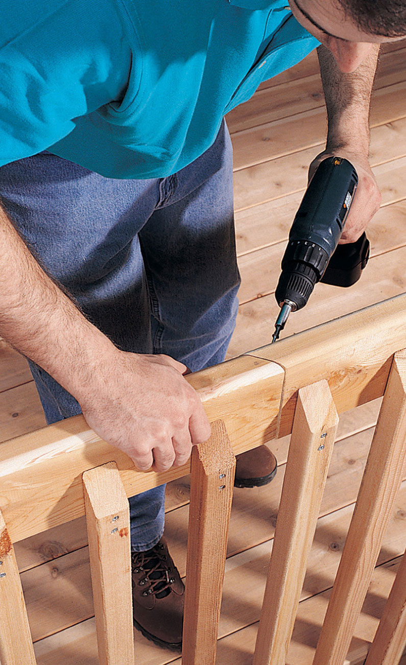
To make a joint in the top rail, cut the ends at 45° and drill a pair of pilot holes. Then fasten the ends together with deck screws.
Attach the corner balusters first (see Face Board Detail, page 293), using a level to ensure that they are plumb. Then use the spacing jig for positioning, and attach the remaining balusters to the deck platform with 3" deck screws.
Measure, mark, and cut the top rail sections (J) to length. Round over three edges (see Railing Detail, page 293) using a router with a 1/2" round-over bit. Cut 45° miters on the ends that meet at the corners.
Hold or clamp the top rail in position, and attach with 2-1/2" deck screws driven through the balusters.
If you need to make straight joints in the top rail, cut the ends of the adjoining boards at 45°. Drill angled 1/8" pilot holes and join with deck screws.
 Inside Corner Deck
A diamond decking pattern helps make this a stunning deck. The location, tucked inside a corner of the house, creates an accessible area for small get-togethers, large parties, simple outdoor meals, and relaxing. The location offers privacy, shade, and a place out of the wind. Although we’ve left the posts exposed, you can create an even more integral deck design by adding simple skirting around the base.
The design calls for double joists and blocking for extra strength and stability where decking boards butt together. Joists are spaced 12" on center to support diagonal decking. It takes a little more time to cut the decking boards and match the miter cuts, but the results are spectacular and well worth the effort. The addition of a few low-voltage lights would make this a fabulous nighttime deck as well.
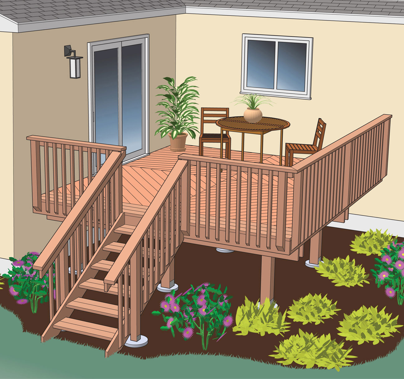
A nested deck is the perfect way to exploit a shaded inside corner, and the position could not be more accessible from the house.
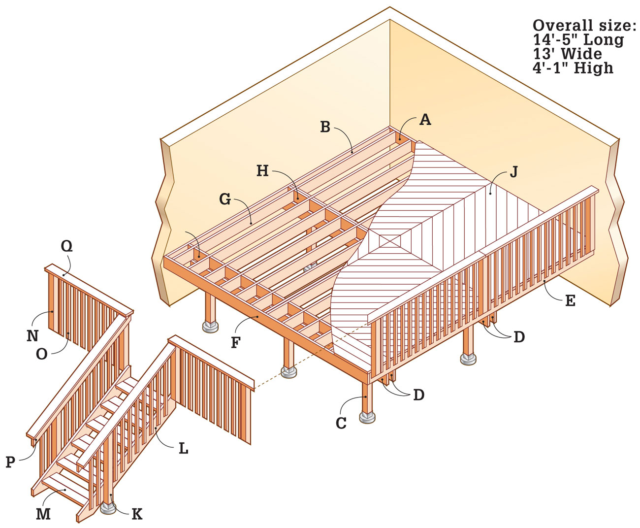
Supplies
10"-diameter footing forms (6)
8"-diameter footing forms (2)
J-bolts (8)
6 × 6" metal post anchors (6)
4 × 4" metal post anchors (2)
2 × 8" single joist hangers (50)
2 × 8" double joist hangers (20)
1 1/2 × 10" angle brackets (12)
3" galvanized deck screws
2-1/2" galvanized deck screws
16d galvanized nails
Joist hanger nails
1/2 × 4" lag screws and washers (78)
1/4 × 1 1/4" lag screws (96)
1/2 × 7" carriage bolts, washers, and nuts (12)
Exterior silicone caulk (6 tubes)
Concrete as needed
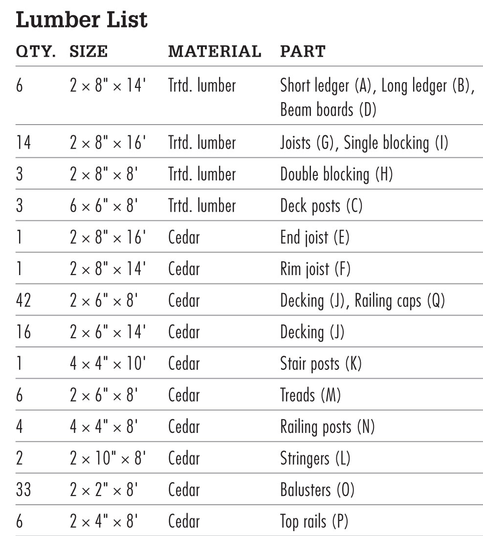
Elevation

Stairway Detail
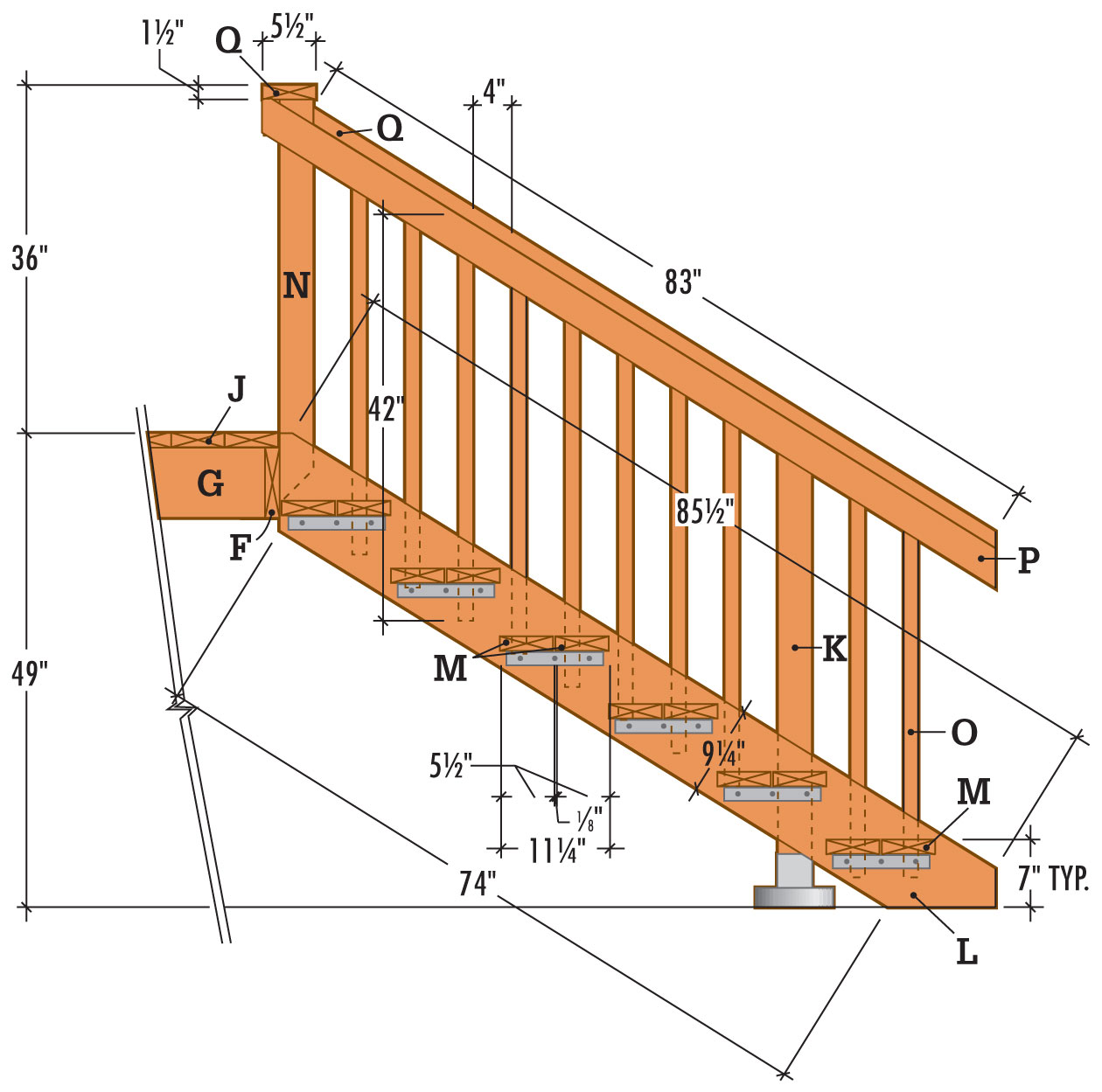
 How to Build an Inside Corner Deck
The inside angle of the house should form a right angle. If there is a slight deviation, use shims behind the ledger to create a 90° angle in the corner.
To show where the ledgers will be attached to the house, draw outlines on the wall, using a level as a guide. To locate the top of the ledger outline, measure down from the indoor floor surface 1" plus the thickness of the decking boards. This height difference prevents rain and melting snow from seeping into the house.
Measure and cut the ledgers to length. They will be shorter than the outline on the wall to allow for the width of the rim joist and end joist. (See pages 62 to 68 for information about attaching ledgers on different types of siding.)
Drill pairs of 3/8" pilot holes through the ledgers at 16" intervals. Counterbore the pilot holes 1/2" with a 1 3/8" spade bit.
Brace the ledgers in place, and use a ratchet wrench to attach the ledgers to the walls with 1/2 × 4" lag screws and washers. Seal the screw heads and all cracks between the wall and ledger with silicone caulk.
To locate the footings, stretch mason’s strings between the ledgers and 2 × 4 supports, known as batterboards.
Referring to the measurements shown in the Framing Plan (page 300), mark the centerlines of the footings on the ledgers, and drive a nail into the ledger at each location.
Set up temporary batterboards and stretch a mason’s string out from the ledger at each location. Make sure the strings are perpendicular to the ledger.
Check the mason’s strings for square, using the 3-4-5 triangle method. From the point where each string meets the ledger, measure 3 ft. along the ledger and make a mark. Next, measure 4 ft. out along the string and mark with tape. The distance between the points on the ledger and the string should be 5 ft. If it’s not, adjust the string position on the batterboard accordingly.
Drop a plumb bob to transfer the footing centerpoints to the ground, and drive a stake to mark each point. Remove the strings.
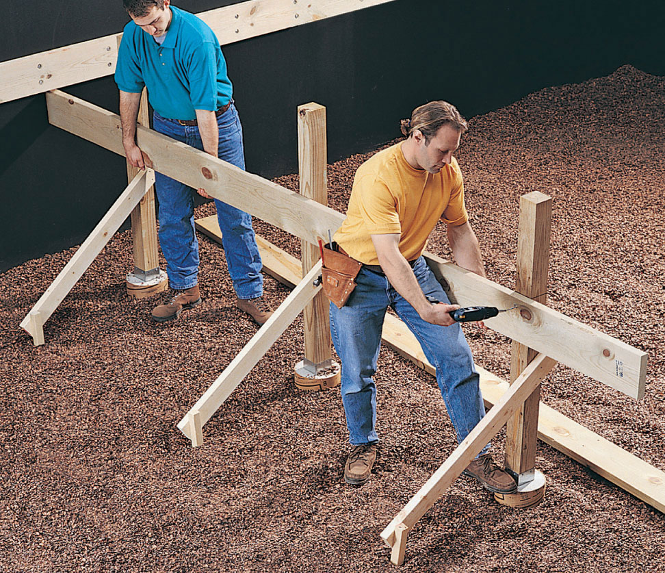
Position the beam against the posts, and attach it temporarily with deck screws. Note: This method of joinery is no longer allowed in some regions. Consult your building department.
Dig the post footings using a clamshell digger or power auger. Pour 2" to 3" of loose gravel into each hole for drainage. Note: Make sure the footing size and depth comply with your local building code, which may require flaring the base.
Cut the footing forms to length, using a reciprocating saw or handsaw, and insert them into the footing holes so that they extend 2" above grade. Pack soil around the forms for support, and fill the forms with concrete, tamping with a long stick or rod to eliminate any air pockets.
Screed the tops of the footings flush, using a 2 × 4. Insert a J-bolt into the wet concrete of each footing, and set it, with 3/4" to 1" of thread exposed. Retie the mason’s strings and position each J-bolt at the exact center of the post location, using the plumb bob as a guide. Clean the bolt threads before the concrete sets.
Lay a long, straight 2 × 4 flat across each row of footings, parallel to the short ledger. With one edge tight against the J-bolts, draw a reference line across the top of each footing.
Center a metal post anchor over the J-bolt on each footing, and square it with the reference line. Attach the post anchors by threading a nut over each bolt and tightening with a ratchet wrench.
Working from a plywood platform, install double blocking to support the ends of the deck boards. Attach the blocking by alternating end nailing with using joist hangers.
Cut the posts, leaving an extra 6" for final trimming. Place each post in an anchor and tack it in place with one nail.
With a level as a guide, use braces and stakes to ensure that each post is plumb. Finish nailing the posts to the anchors.
Determine the height of the inside beam by extending a straight 2 × 4 from the bottom edge of the long ledger across the row of posts. Level the 2 × 4, and draw a line on the posts. Use the same method to determine the height of the outer beam. Note: The sandwich beam construction described here is no longer allowed by most local codes. If sandwich beams are not allowed by your local code, use special hangers or larger posts to support the blocked beam on the top of the posts.
Cut the beam boards (D), leaving an extra few inches for final trimming.
Position one beam board, crown up, against the row of posts. Tack the board in place with deck screws.
Attach the remaining beam boards to the posts in the same way.
Drill two 1/2" holes through the boards and posts at each joint. Secure the beam boards to the posts with carriage bolts, using a ratchet wrench.
Cut the tops of the posts flush with the tops of the beams, using a reciprocating saw or handsaw.
A double joist at the center of the deck provides extra support for the ends of the decking boards.
Measure, mark, and cut the end joist (E) and the rim joist (F), using a circular saw.
Attach the end joist to the short ledger and the rim joist to the long ledger, using 16d galvanized nails.
Nail the rim joist to the end joist.
Toenail the end joist to the tops of the beams, and cut the ends of the beams flush with the end joist.
Measure, mark, and install the double center joist at the precise center of the deck with double joist hangers.
Measure both ways from the double joist, and mark the centerpoints of the remaining joists at 12" intervals. Using a combination square, mark the outlines of the joists on the ledger, beams, and rim joist.
Nail the joist hangers to the short ledger and rim joist using a scrap 2 × 8 as a spacer to achieve the correct spread for each hanger.
Cut the joists (G) to length. Insert the joists into the hangers with the crown up, and attach them with joist hanger nails. Align the joists with the marks on the beams and toenail them in place.
The ends of the decking boards in the diamond pattern are supported by a row of double blocking at the center of the pattern and a row of single blocking at the edge of the pattern.
To locate the rows of blocking, measure from the inside corner of the house along the long ledger (see Framing Plan, page 300). Drive one screw or nail at 78", and another at 156". Make corresponding marks across from the ledger on the end joist.
Snap chalk lines across the joists, between the ledger and the end joist. The line at 78" is the centerline of the double blocking. The line at 156" is the outer edge of the single blocking. Don’t be concerned if the blocking is not directly over the beams.
Cut double blocking pieces from 2 × 8s nailed together with 10d galvanized nails.
Install the blocking by alternating end nailing and using galvanized joist hangers.
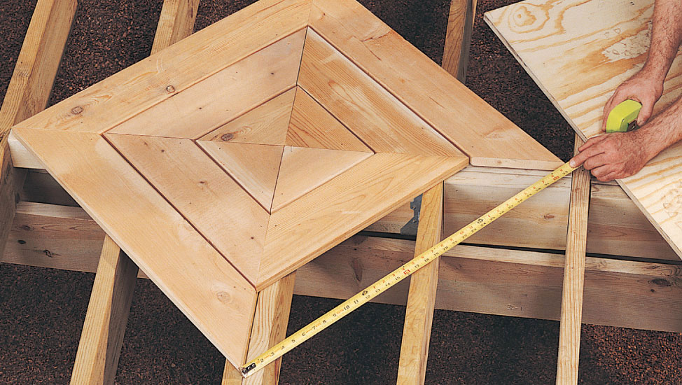
To achieve the best fit, measure the actual length of the last deck board in each course before cutting.
Except for the three rows of straight decking at the top of the stairway, the decking is laid in a diamond pattern.
Begin at the center of the diamond pattern, where the double joist and the double blocking intersect. Cut four identical triangles, as large as possible, from 2 × 6" cedar stock.
Drill 1/8" pilot holes in the ends, position the pieces as shown on page 303, and attach with 3" deck screws.
To install the remaining courses, measure, cut, drill, and attach the first three boards in each course. Then, measure the actual length of the last board to achieve the best fit. For best results, install the decking course by course. Maintain a 1/8" gap between courses.
Once the diamond decking pattern is complete, cut and install the three remaining deck boards.
For the position of the stairway footings, refer to the Framing Plan on page 300. Locate the footings by extending a 2 × 4 from the deck, perpendicular to the rim joist, dropping a plumb bob, and marking the centerpoints on the ground with stakes.
Dig postholes with a clamshell digger or an auger, and pour footings using the same method as for the deck footings. Insert J-bolts, leaving 3/4" to 1" of thread exposed. Allow the concrete to set. Attach metal post anchors.
Cut the stairway posts (K) to length, adding approximately 6" for final trimming. Place the posts in the anchors.
Use a level to ensure that the posts are plumb, and attach the posts to the anchors with 16d galvanized nails.
Cut the stringers (L) to length and use a framing square to mark the rise and run for each step (see Stairway Detail, page 301). Draw the tread outline on each run. Cut the angles at the ends of the stringers with a circular saw. (For a more detailed description of stairway construction, see pages 140 to 159.)

Drill pilot holes and then attach the treads to the stringers, using 1 1/4" lag screws and angle brackets.

Fasten the stair to the deck with a ratchet wrench, using 4" lag screws.
Position an angle bracket flush with the bottom of each tread outline. Drill 1/8" pilot holes in the stringers, and attach the angle brackets with 1 1/4" lag screws.
The treads (M) fit between the stringers, and the stringers fit between the stairway posts. Measure and cut the treads (M) to length, 3" shorter than the distance between the stairway posts.
Assemble the stairway upside down on sawhorses. Mark and drill 1/8" pilot holes at the ends of the treads. Position each front tread with its front edge flush to the tread outline, and attach to the angle brackets with 1/4 × 1 1/4" lag screws.
Attach the rear treads in similar fashion, leaving a 1/8" gap between treads.
Position the stairway in place against the edge of the deck, making sure the top of the stringer is flush with the surface of the deck. From underneath the deck, drill 1/4" pilot holes through the rim joist into the stringers. Attach the stringers to the rim joist with 4" lag screws, using a ratchet wrench.
To fasten the stairway to the stair posts, drill two 1/4" pilot holes through each stringer into a post. Counterbore the pilot holes 1/2" deep with a 1 3/8" spade bit, and use a ratchet wrench to drive 4" lag screws with washers. Seal the screw heads with silicone caulk.
Cut the railing posts (N) and balusters (O) to length (see Railing Detail, page 301) with a power miter saw or circular saw. Cut the tops square and the bottoms at 45° angles.
Drill two 3/8" pilot holes at the bottom end of each railing post, positioned so the lag screws will attach to the rim joist. Counterbore the holes 1/2" deep with a 1 3/8" spade bit.
Drill two 1/8" pilot holes near the bottom of each baluster, spaced 4" apart. At the top of each baluster, drill a pair of 1/8" pilot holes spaced 1 1/2" apart.
With the help of a combination square, draw the outlines of the railing posts around the perimeter of the deck. The posts at the corner must be spaced so there is less than 4" between them.
Hold each railing post in its position, with the end 1 1/2" above the bottom edge of the deck platform (see Railing Detail, page 301). Make sure the post is plumb, and insert an awl through the counterbored holes to mark pilot hole locations on the deck (or use a longer bit).
Set the post aside and drill 3/8" pilot holes at the marks. Attach the railing posts to the deck with 1/2 × 4" lag screws and washers. Seal the screw heads with silicone caulk.
Cut the top rails (P) to length with the ends mitered at 45° where they meet in the corner. Attach them to the railing posts with 3" deck screws, keeping the edges of the rails flush with the tops of the posts.
To position the balusters, measure the total distance between two railing posts, and mark the centerpoint on the top rail. The two railing sections on the long side of this deck will have a baluster at the centerpoint; the two railing sections on the stairway side will have a space at the centerpoint. Note: If the dimensions of your deck vary from the plan, calculate whether you will have a baluster or a space at the center of each section.
Cut a spacer slightly less than 4" wide. Start at the center of each railing section, and position either a baluster or a space over the line. Measure out from the center both ways, marking the outlines of the balusters on the top rail. The end spaces may be narrow, but they will be symmetrical.
To install the balusters, begin next to a railing post and make sure the first baluster is plumb. Install the remaining balusters, holding each one tight against the spacer and flush with the top rail. Attach the balusters with 2-1/2" deck screws.
Cut the deck railing cap (Q) to length, with the ends mitered at 45° where they meet in the corner. Position the railing cap sections so the inside edge overhangs the inside edge of the top rail by 1/4". Attach the cap with 3" deck screws.
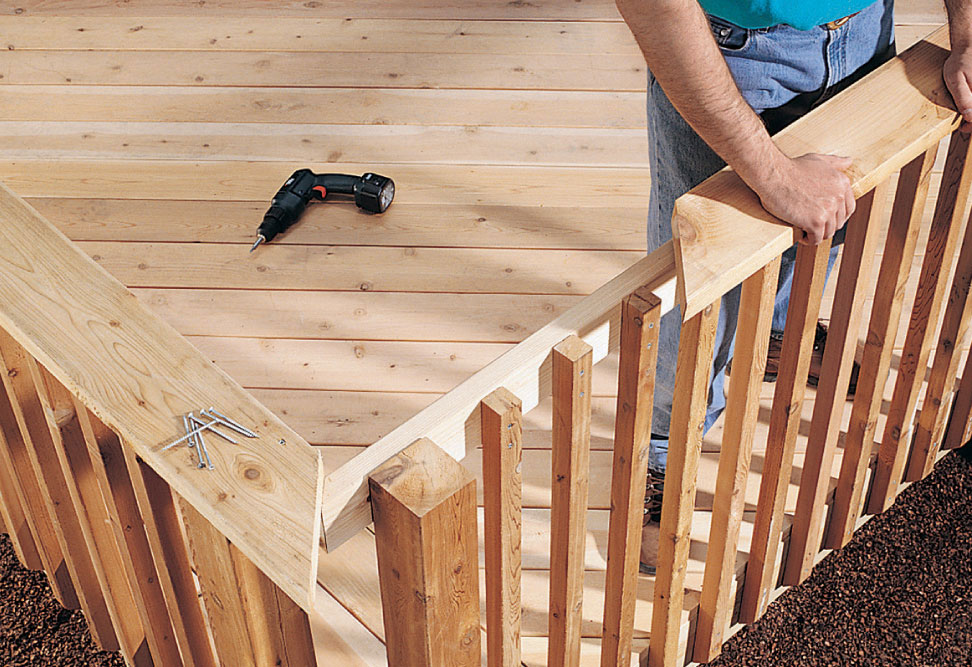
After the top rail and balusters have been installed, install the railing cap with its inside edge overhanging the inside face of the top rail by 1/4".
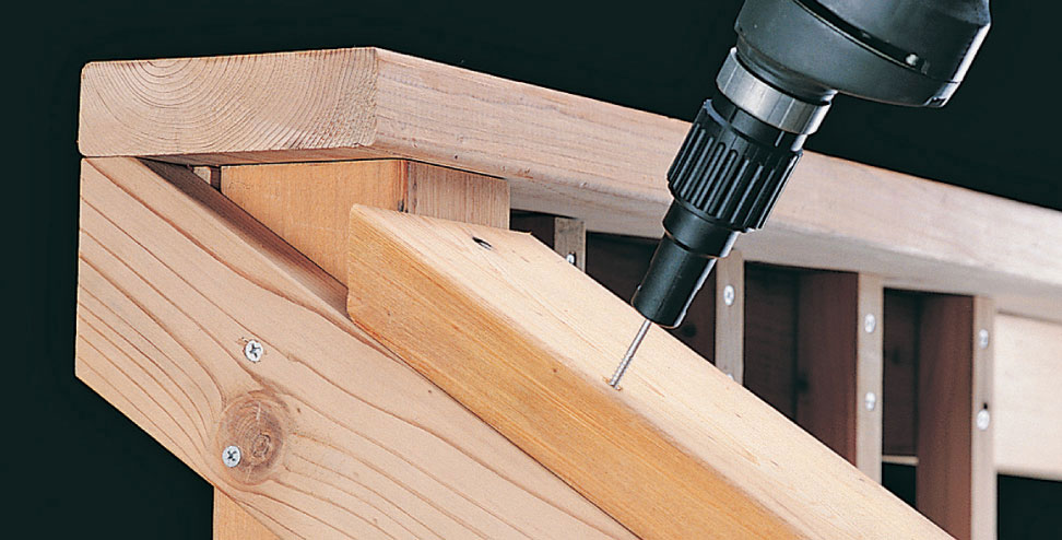
With the stairway top rail cut to size and installed, attach the railing cap with deck screws.
Determine the exact size and shape of the stairway top rail. Tack a cedar 2 × 4 across the faces of the stairway post and deck post with 10d galvanized nails. Make sure the angle of the 2 × 4 is parallel with the angle of the stringer below.
On the back side of the 2 × 4, mark the outline of the deck railing post and the end of the deck top rail. On the stairway post, mark a diagonal cutoff line at the top edge of the 2 × 4. At the lower end of the 2 × 4, use a level to mark a plumb cutoff line directly above the end of the stringer.
Remove the 2 × 4 and make the cuts.
Drill 1/8" pilot holes through the stairway top rail. Place in position and attach with 2-1/2" deck screws.
To trim the top ends of the stairway balusters, hold a baluster against the stairway post and draw a diagonal cut line along the top edge of the rail. Trim the baluster. Using this baluster as a template, mark and cut the remaining stairway balusters.
Install the stairway balusters with 2-1/2" deck screws, using the same procedure as for the deck balusters.
Measure the railing caps for the stairway. Cut the caps to size, with the upper ends beveled to fit against the deck posts, and the lower ends beveled to align with the end of the top rail. Install the caps by drilling 1/8" pilot holes and attaching them with 2-1/2" deck screws.
 Wraparound Deck
By wrapping around an outside corner of your house, this versatile deck increases your living space and lets you take advantage of views in several directions. The plan also creates two symmetrical areas for sitting or relaxing, providing space for two distinct activities. Our plan also calls for a front stairway for easy access to your yard or garden. The horizontal rails and notched posts provide striking visual elements that enhance the deck’s overall design and add to its intimate nature.
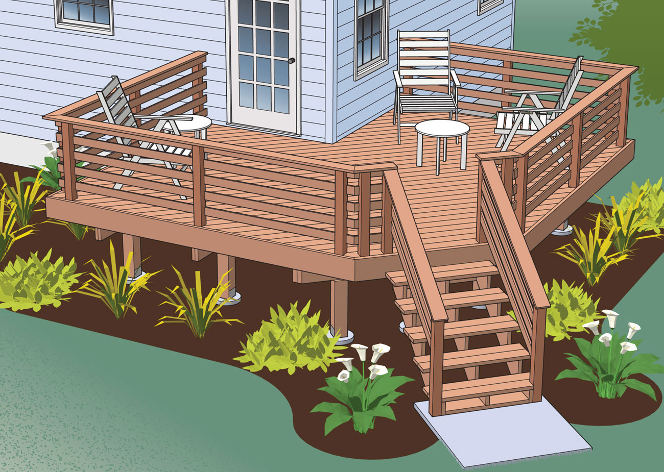
The unusual orientation of this deck to the house creates naturally separate areas on the deck, and allows for maximum views out over the landscaping.
Elevation
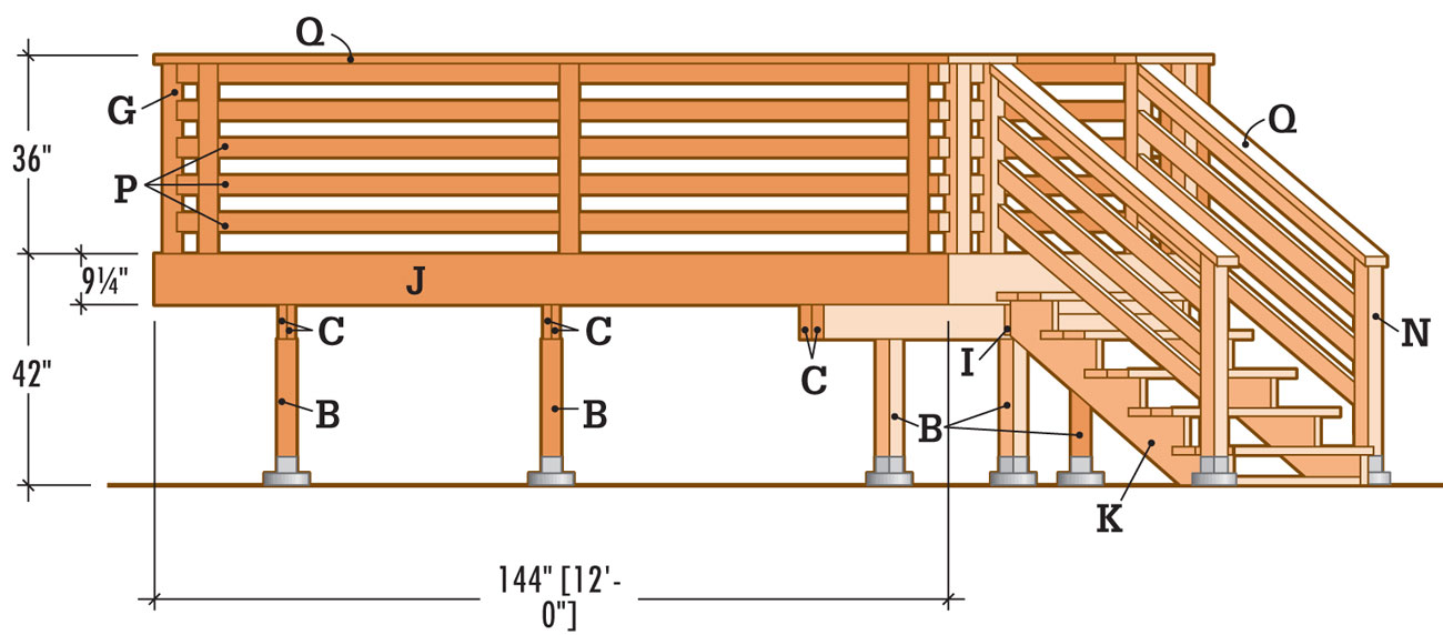
Stairway Detail
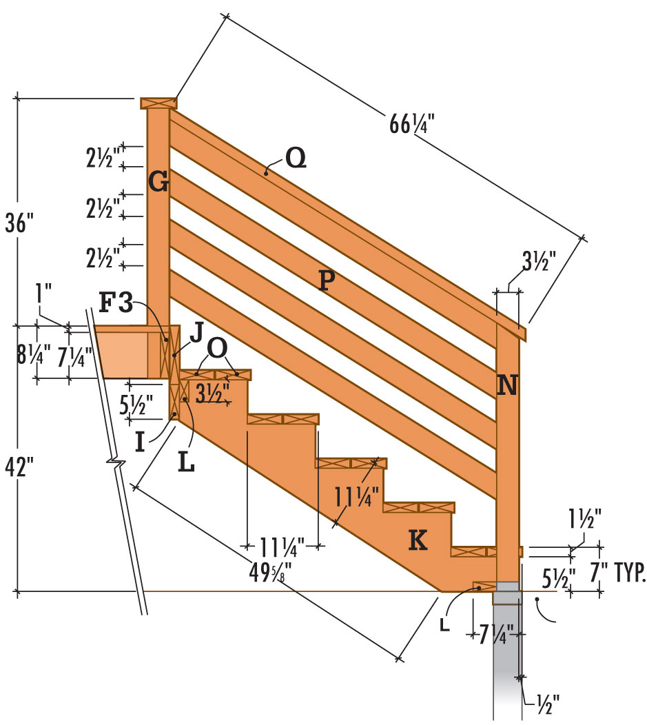
Footing Location Diagram
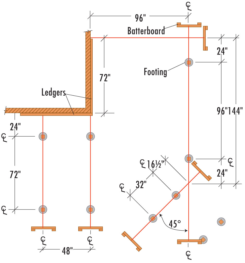
Corner Post Detail
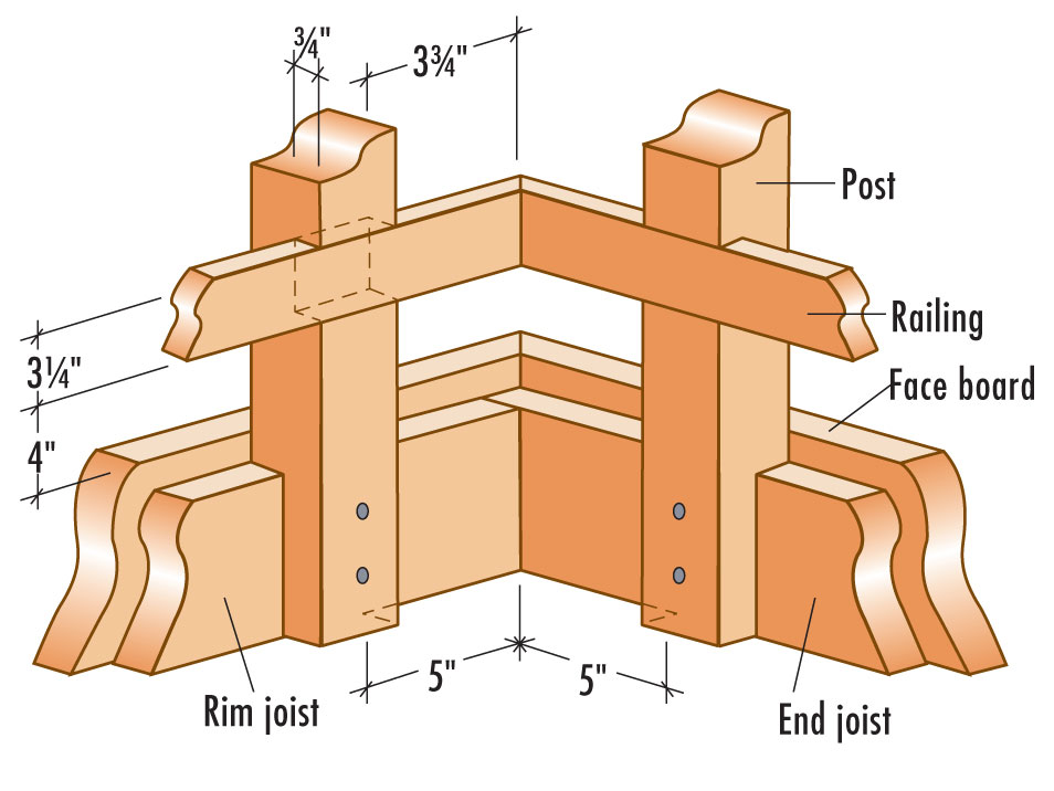
 How to Build a Wraparound Deck
Draw a level outline on the siding to show where the ledgers and the adjacent end joist and rim joist will fit against the house.
Position the top edge of the ledgers so that the surface of the decking boards will be 1" below the indoor floor level. This height difference prevents rainwater or melted snow from seeping into the house. Draw the outline long enough to accommodate the thickness of rim joist F-1 and end joist E-2.
Cut out the siding along the outline with a circular saw. To keep the blade from cutting the sheathing underneath the siding, set the blade depth to the same thickness as the siding. Finish the corners of the cutout with a chisel, holding the beveled side in to ensure a straight cut. Cut galvanized flashing to the length of the cutout, using metal snips, and slide the flashing up under the siding.
Measure and cut the ledgers (A) to length from pressure-treated lumber, using a circular saw. Remember, the ledger boards should be shorter than the overall length of the cutouts. Position the ledgers in the cutout, underneath the flashing, and brace them in place. Fasten them temporarily with deck screws.
Drill pairs of 3/8" pilot holes through the ledger and sheathing and into the house header joist at 2 ft. intervals. Counterbore each pilot hole 1/2" deep, using a 1 3/8" spade bit. Attach the ledgers to the wall with 1/2 × 4" lag screws and washers, using a ratchet wrench.
Apply a thick bead of silicone caulk between the siding and the flashing. Also seal the lag screw heads and any gaps between the wall and the ledger.
Referring to the Footing Location Diagram (page 309), stretch mason’s strings across the site, using 2 × 4 batterboards. Check the mason’s strings for square, using the 3-4-5 triangle method. From the point where each string meets the ledger, measure 3 ft. along the ledger and make a mark. Next, measure 4 ft. out along the mason’s string and mark with tape. The distance between the points on the ledger and the string should be 5 ft. If not, adjust the mason’s strings accordingly. Measure along the strings to locate the centerpoints of the footings. Mark the locations with tape.
Drop a plumb bob at the tape locations, and drive stakes into the ground to mark the centerpoints of the footings. Remove the mason’s strings and dig holes for the footings using a clamshell digger or power auger. Pour 2" to 3" of loose gravel into each hole for drainage. Make certain the hole dimensions comply with your local building code, which may require flaring the footings at the base. Cut the footing forms to length using a reciprocating saw or handsaw. Insert the forms into the holes, leaving 2" of each form above grade. Pack soil around the forms.
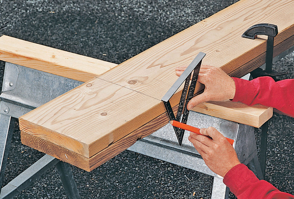
Use a speed square to mark a 22-1/2° miter cut where the ends of beams C-3 and C-4 fit together.
Fill the forms with concrete and tamp the concrete with a long stick to eliminate any air pockets. Screed the tops flush with a flat 2 × 4. Insert a J-bolt into each footing, leaving 3/4" to 1" of thread exposed.
Retie the mason’s strings and drop a plumb bob to position each J-bolt at the exact center of the footing. Clean the bolt threads before the concrete sets.
Start by laying a long, straight 2 × 4 flat across each pair of footings. With one edge tight against the J-bolts, draw a reference line across each footing.
Place a metal post anchor on each footing, center it over the J-bolt, and square it with the reference line. Thread a nut over each J-bolt and tighten each of the post anchors in place.
Cut the posts (B) to their approximate length, adding several inches for final trimming. Place the posts in the anchors and tack them into place with one nail each.
With a level as a guide, use braces and stakes to plumb the posts. Once the posts are plumb, finish nailing them to the anchors. To determine the height of the posts (except for the staircase front posts, which should be cut to the length indicated), make a mark on the house 7 1/4" down from the bottom edge of the ledger. Use a straight 2 × 4 and a level to extend this line across a post. Transfer this line to the remaining posts. Cut the posts off with a reciprocating saw or a handsaw and attach post-beam caps to the tops using 8d nails. Pour the railing post fittings using the same method.
Cut the beams from 2 × 10" lumber, adding several inches to each beam for final trimming. Position the beam boards (C) so the crowns face the same direction, and fasten them together with 10d galvanized nails spaced every 16".
Position beams C-1 and C-2 in their post-beam caps and attach them with nails. Mark and cut the angled end of beam C-3 by mitering it at 22-1/2°. Position the beam in the post caps.
Make a 22-1/2° miter cut at one end of beam C-4 to form a 45° corner with beam C-3. Leave the other end long for final trimming. Place beam C-4 in the post-beam caps. Fit the beams tightly together, fasten them with 3" deck screws, and attach them to the post caps with 8d nails.
Referring to the Framing Plan on page 308, cut rim joist F-1 to final length, and cut end joist E-1 generously long, to allow for final trimming.
Fasten one end of rim joist F-1 to the ledger with 16d galvanized nails. Rest end joist E-1 in place on beams C-1 and C-2. Fasten F-1 and E-1 together with deck screws. Use a framing square to finalize the location of E-1 on the beams. Mark the beams and trim them to length. Toenail E-1 in place on the beams.
Cut end joist E-2 to length. Install it by nailing it to the end of the ledger, checking for square, and toenailing it to the top of beam C-3. Trim the beam to length. Mark the outlines of the inner joists (D) on the ledger, beams, and rim joist F-1 (see Framing Plan, page 308), using a tape measure and a combination square.
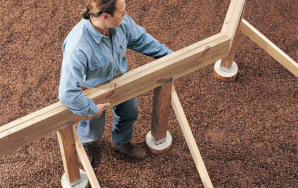
Fit beam C-4 tightly against beam C-3 and attach the two beams to each other with deck screws.
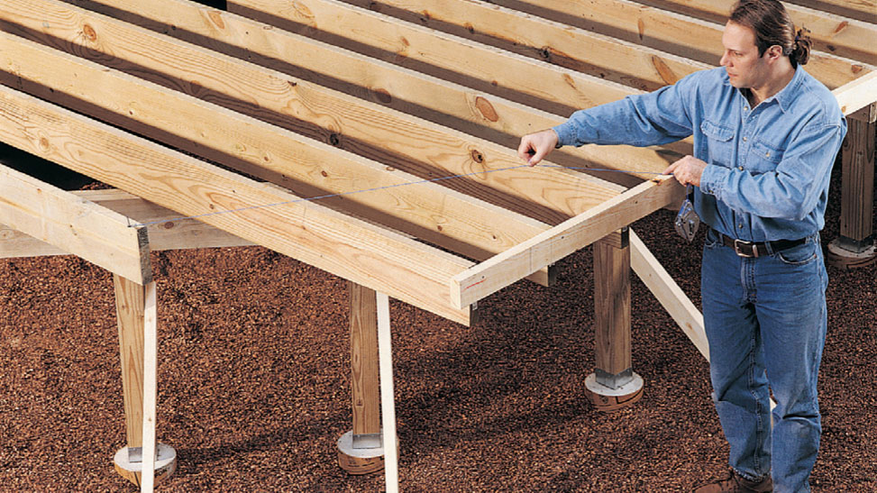
Mark the three remaining inside joists for cutting by snapping a chalk line. Brace and miter-cut the three inside joists.
Attach joist hangers to the ledger and rim joist F-1 with 1 1/2" joist hanger nails, using a scrap 2 × 8 as a spacer to achieve the correct spread for each hanger. Note: Spacing between the joists is irregular to accommodate the installation of railing posts.
Place the inside joists in the hangers on the ledger and on rim joist F-1, crown up, and attach them with 1 1/2" joist hanger nails. Be sure to use all the nail holes in the hangers. Toenail the joists to the beams and leave the joists long for final trimming.
Mark the final length of the inside joists by making a line across the tops of the joists from the end of end joist E-2. Check for square. Brace the inside joists by tacking a board across their edges for stability. Cut them to length with a circular saw.
Cut rim joist F-2 long to allow for final trimming, and nail into position with 16d galvanized nails.
To mark the remaining joists for trimming at a 45° angle, make a mark 139" from the 90° corner on end joist E-1. Make a second mark 139" from the other 90° corner along rim joist F-2. The distance between these two points should be at least 70". If necessary, move the line back until it measures 70". Regardless of the overall dimensions of your deck, this length will ensure adequate space for mounting the railing posts at the top of the stairway.
Mark the last three joists for cutting by snapping a chalk line between the marked points on end joist E-1 and rim joist F-2. Transfer the cut marks to the faces of the joists with a combination square, and cut the miters with a circular saw.
Measure, cut, and attach rim joist F-3 across the angle with deck screws.
Drill pilot holes through the posts and into the rim joists, and attach the posts with lag screws. Note the unnotched stairway post.
Cut the railing posts (G) to size and notch the lower ends to fit around the rim joists (see Railing Detail, page 309). Note: Many modern codes prohibit notching railing posts for installation. Check your local code and adjust this design as necessary to attach unnotched posts to the rim joists or beams.
Clamp all but two of the posts together to lay out and cut 3/4 × 3 1/2" notches, or dadoes, for the horizontal rails. Note: The posts at the stairway are not notched for rails.
Cut the dadoes by making a series of parallel 3/4"-deep cuts within each 3 1/2" space, about 1/4" apart, with a circular saw. Knock out the waste wood between the cuts, using a hammer. Then, chisel smooth the bottom of each dado.
To locate the railing posts on the diagonal corner, find the centerline of rim joist F-3 and measure 18" in both directions. These points are the inner faces of the railing posts and the outer faces of the stringers. Drill 1/4" pilot holes through the railing posts into the rim joist, and secure the posts with lag screws.
To position the corner railing posts, measure 3" both ways from the outside corners of rim joist F-3. Predrill the posts, and use a ratchet wrench to attach them to the rim joists with lag screws.
Use the Framing Plan (page 308), and the Corner Post Detail (page 309), to locate the remaining railing posts.
If possible, buy decking boards that are long enough to span the deck.
Measure, mark, and cut the decking (H) to size, making notches to fit around the railing posts. Position the first board above the stairway, and attach it by driving a pair of deck screws into each joist.
Position the remaining decking boards so that the ends overhang the deck, leaving a 1/8" gap between the boards to allow for drainage.
Where more than one board is required to span the deck, cut the ends at 45° angles and make the joint at the center of a joist.
Snap a chalk line flush with the edge of the deck, and cut off the overhanging ends of the deck boards with a circular saw set for a 1 1/2"-deep cut.
Measure, mark, and cut the stairway nailer (I) to size and attach it to the rim joist with mending plates and deck screws (see Stairway Detail, page 309).
Measure, mark, and cut the face boards (J) to length, making 45° miter cuts at the right angle corners and 22-1/2° miter cuts at the stairway corners. Attach the face boards to the rim and end joists with pairs of deck screws at 2 ft. intervals.
Lay out and cut the stringers (K) to size, according to the Stairway Detail (page 309). Mark the rises and runs with a framing square. Cut the notches with a circular saw, using a reciprocating saw or handsaw to finish the corners.
Measure, mark, and cut the gussets (L) to length. Assemble the stairway framework by nailing the gussets in place between the outer stringers with 16d nails.
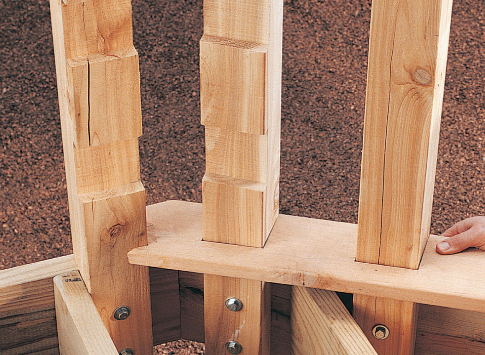
Cut the notches for the first decking board and position it above the stairway.
Drill 1/8" pilot holes through the treads to prevent splitting. Then, attach the treads to the stringers with deck screws, using a power driver.
Position the framework against the deck, and attach with deck screws driven through the upper gusset into the face board and nailer. Position the stringers against the bottom stairway posts, drill pilot holes through the stringers into the posts, and attach them to the posts with 1/2 × 4" lag screws.
Measure, mark, and cut the treads (O) to length. For the bottom treads, use a piece of railing post scrap to trace a line for the notch. Then, cut the notch with a circular saw. Attach the treads to the stringers with deck screws.
Measure and cut to length the 10 ft. rails, each with one end mitered at 45°. Install the rails, using 1 5/8" deck screws. Miter one end of the long rails at 45°. Leave the other end long for final trimming. Clamp each long rail in place and use a straightedge to mark cut lines at the angled corner. Transfer this line to the face of each rail, using a combination square. Remove the rails and miter-cut the ends for the angled corners at 22-1/2°. Reposition the rails and attach them to the railing posts with 1 5/8" deck screws. Measure, mark, and cut the short rails to length with one end mitered at 22-1/2° and the other end cut square.
Fasten the ends of the short rails to the railing posts above the stairway with angle brackets. Use 5/8" galvanized screws to attach the brackets to the rails and 1 5/8" deck screws to attach them to the posts. Attach them to the notched post as well, using 1 5/8" deck screws.
Measure, mark, and cut the deck railing cap (Q), and install it with 3" deck screws.
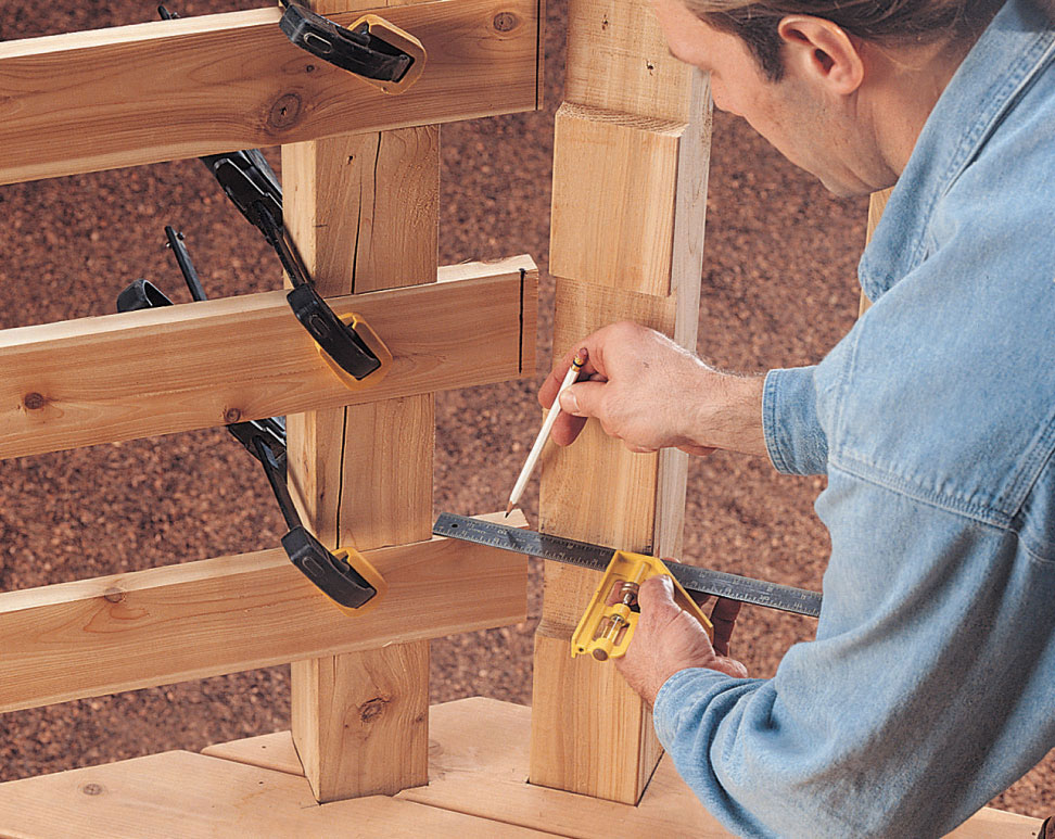
Clamp the long rails, mark the ends, and transfer the lines across the face of the board with a combination square to ensure a tight-fitting 22-1/2° miter with the short rail.
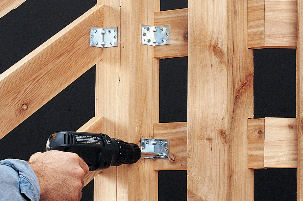
Use angle brackets to attach the stairway railing pieces and angled rails. To attach the brackets to the rails, use 5/8" galvanized screws.
Mark and cut the stairway posts to length. Measure, mark, and cut the stairway railing caps (see Stairway Detail, page 309). Place a cedar 2 × 6 on top of the stairway posts, mark the angles for the ends, and cut to length, allowing for a 1" overhang at the end of the stairway.
Install the stairway railing caps with 3" deck screws. To cut the stairway rails, hold each one tight against the bottom of the cap and mark the ends.
Cut the rails to length so that they fit tight between the posts. To install the rails, mark the positions of the rails on the posts and attach them with angle brackets, using 5/8" screws and 1 5/8" deck screws.
 Angled Deck
Expand your outdoor living space with unusual flair. The design of this attractive deck makes creative use of simple geometry to take advantage of the fact that the eye finds angles and unexpected shapes visually interesting. The look is jazzed up even more with vertical balusters and beefy horizontal rails, topped with interesting decorative finials. It’s a winning look all around.
The deck is also convenient. It’s been designed with a straight staircase, providing direct and simple access to the backyard. Though designed specifically for construction at medium height on level ground, the deck uses heavy-duty posts, beams, joists, and footings. It’s a durable deck that will definitely stand the test of time. It’s also an adaptable design that could easily be altered for installation at a higher level, or on a slope.
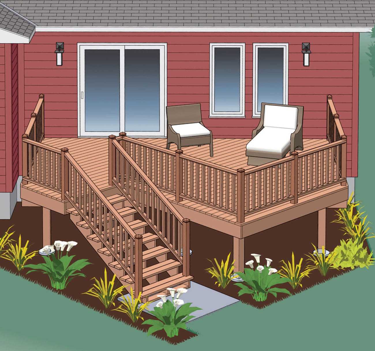
The view from this deck is arresting, and so is the view toward it.
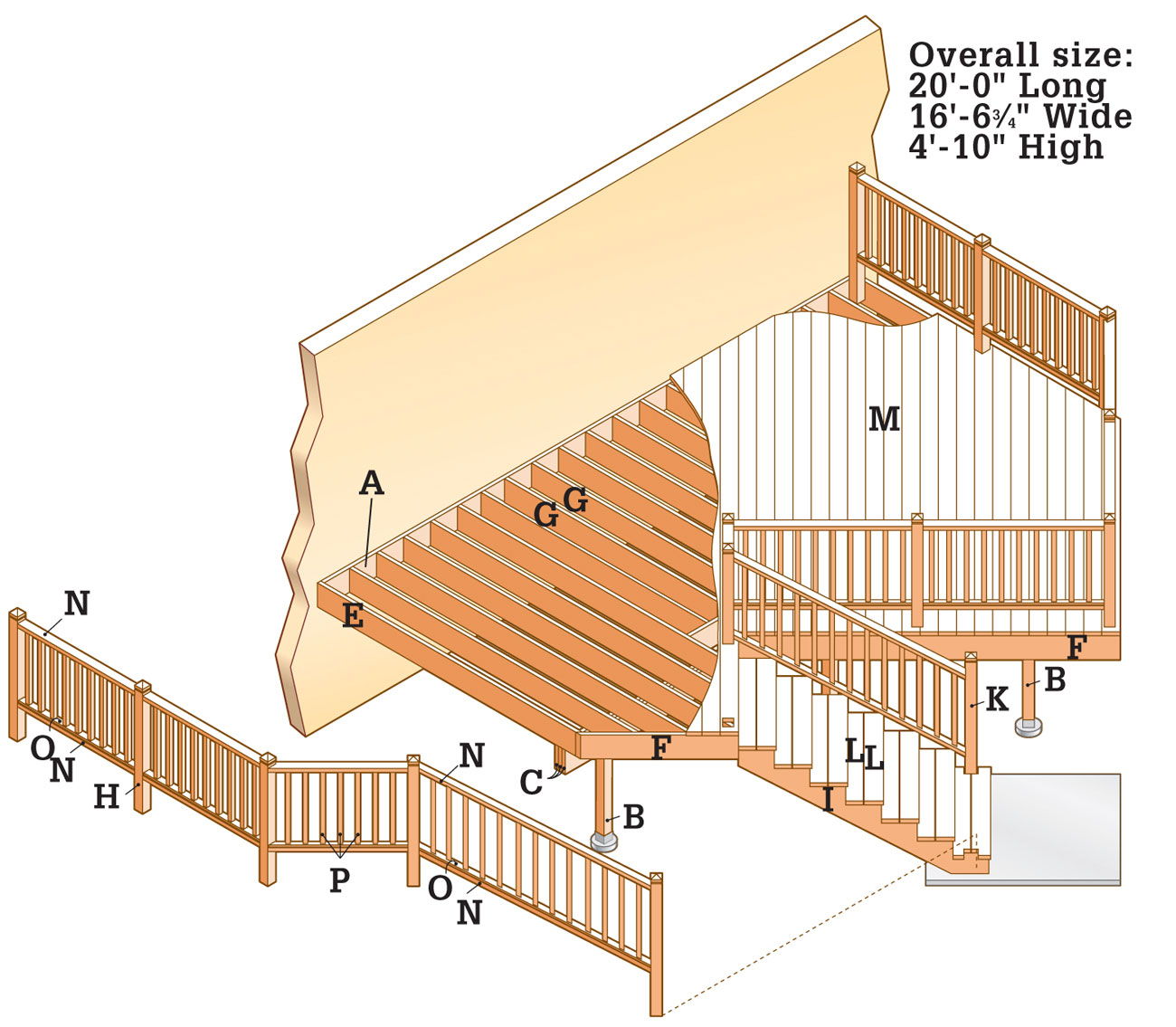
Supplies
12"-diameter footing forms (4)
J-bolts (4)
6 × 6" metal post anchors (4)
90° 2 × 10" joist hangers (22)
45° double 2 × 10" joist hangers (2)
3" galvanized deck screws
1 5/8" galvanized deck screws
3" masonry screws (4)
Joist hanger nails
16d galvanized casing nails
1/2 × 4" lag screws and washers (60)
1/2 × 5" carriage bolts, washers and nuts (22)
Silicone caulk (3 tubes)
Concrete as required
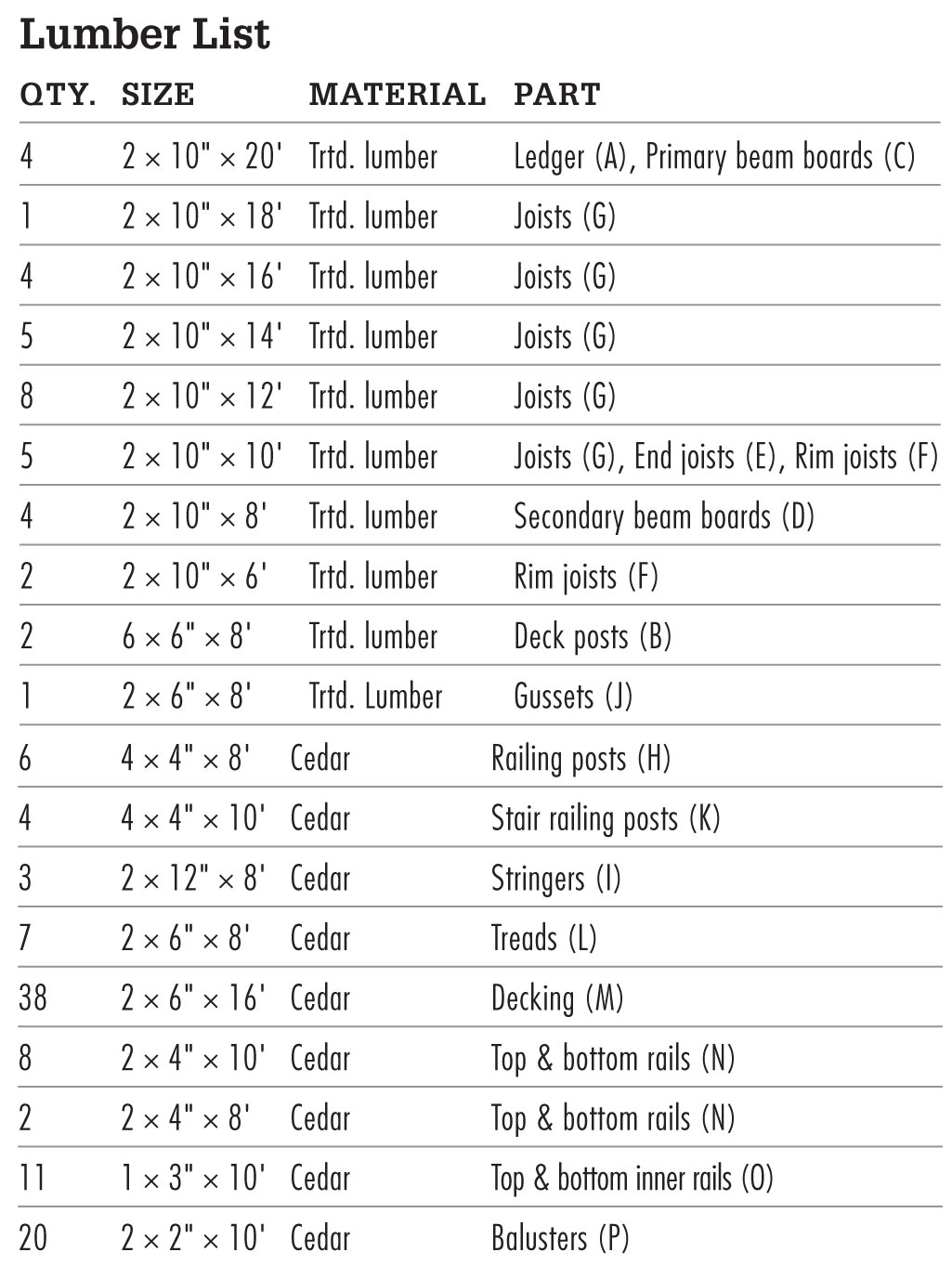
Elevation
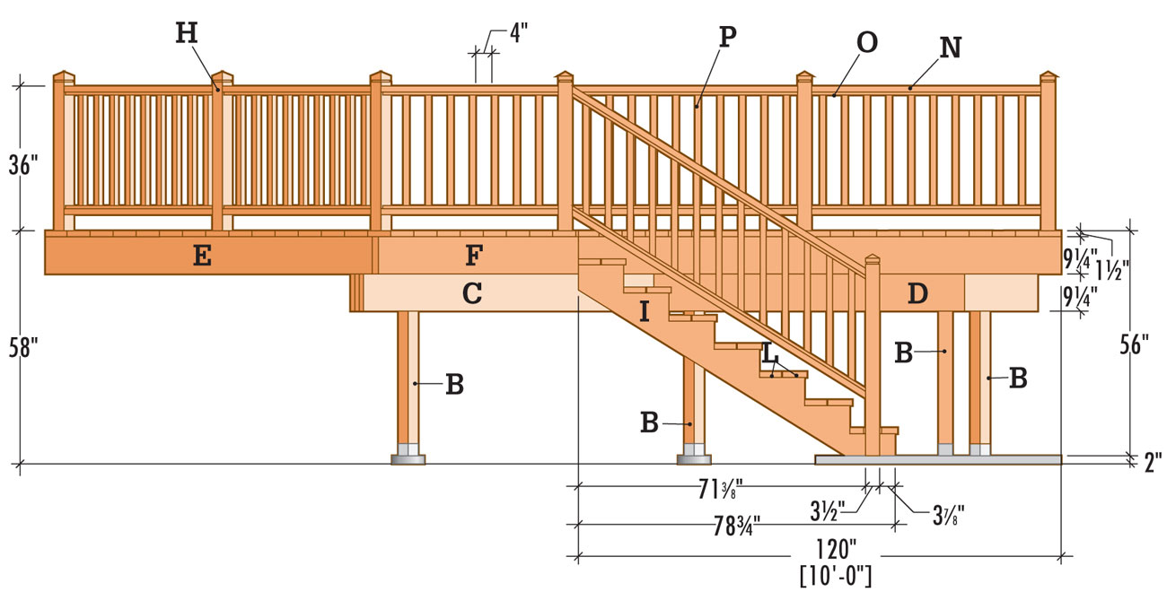
Railing Detail
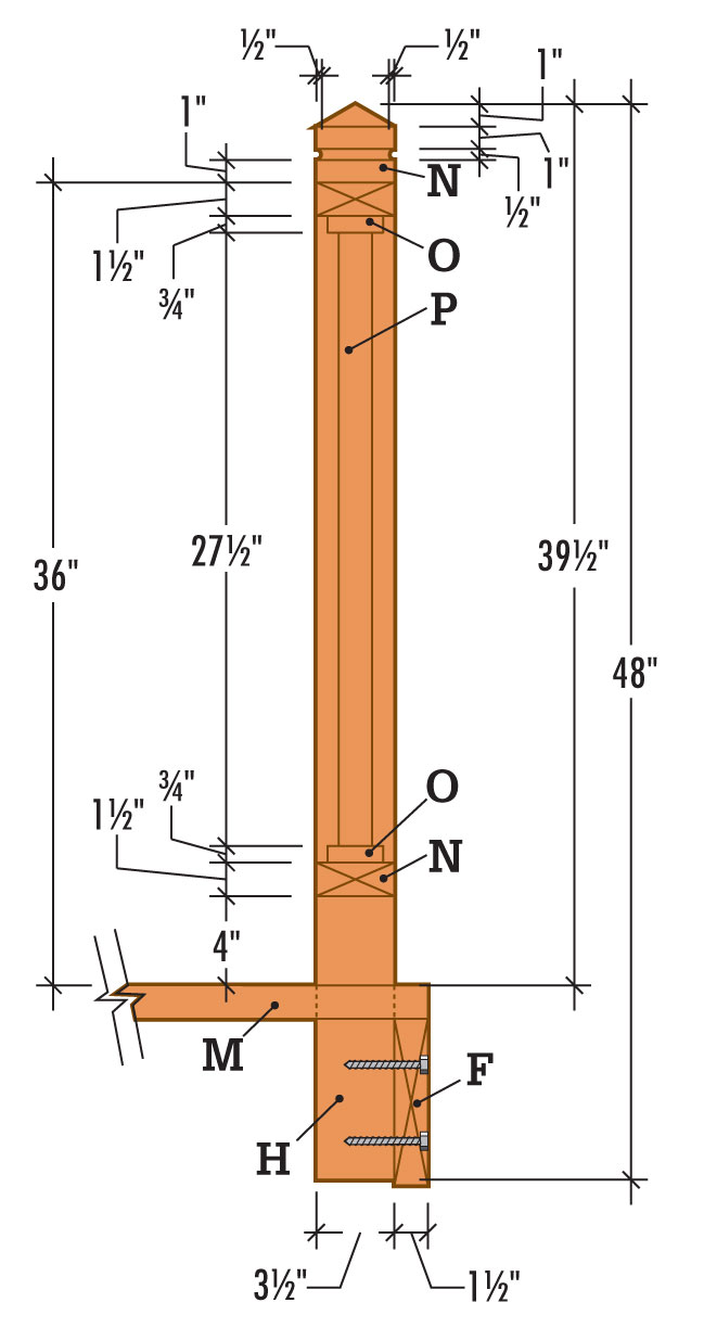
Stairway Detail
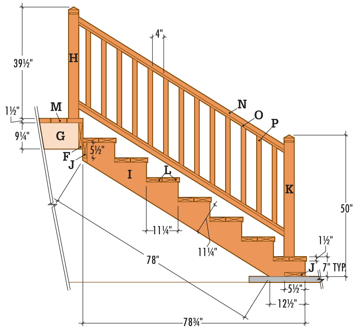
 How to Build an Angled Deck
The ledger anchors the deck and establishes a reference point for building the deck square and level.
Draw a level outline on the siding to show where the ledger and the end joists will fit against the house. Install the ledger so that the surface of the decking boards will be 1" below the indoor floor level. This height difference prevents rainwater or melted snow from seeping into the house.
Cut out the siding along the outline with a circular saw. To prevent the blade from cutting the sheathing that lies underneath the siding, set the blade depth to the same thickness as the siding. Finish the cutout with a chisel, holding the beveled side in to ensure a straight cut.
Cut galvanized flashing to the length of the cutout, using metal snips. Slide the flashing up under the siding at the top of the cutout.
Measure and cut the ledger (A) from pressure-treated lumber. Center the ledger end to end in the cutout, with space at each end for the end joist.
Brace the ledger into position under the flashing. Tack the ledger into place with galvanized nails.
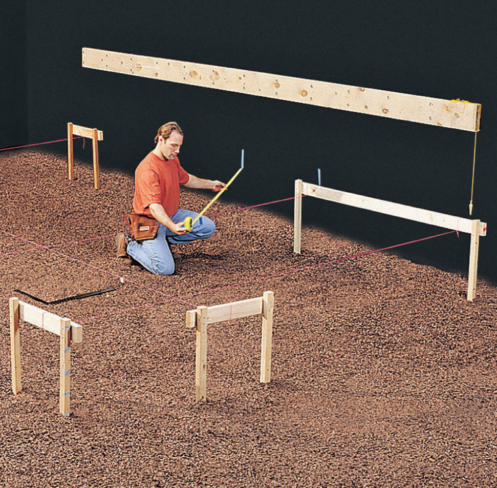
After attaching the ledger, drop a plumb line to a convenient height and stretch mason’s strings. Mark footing locations with tape, and use the 3-4-5 triangle method to verify that the strings are square.
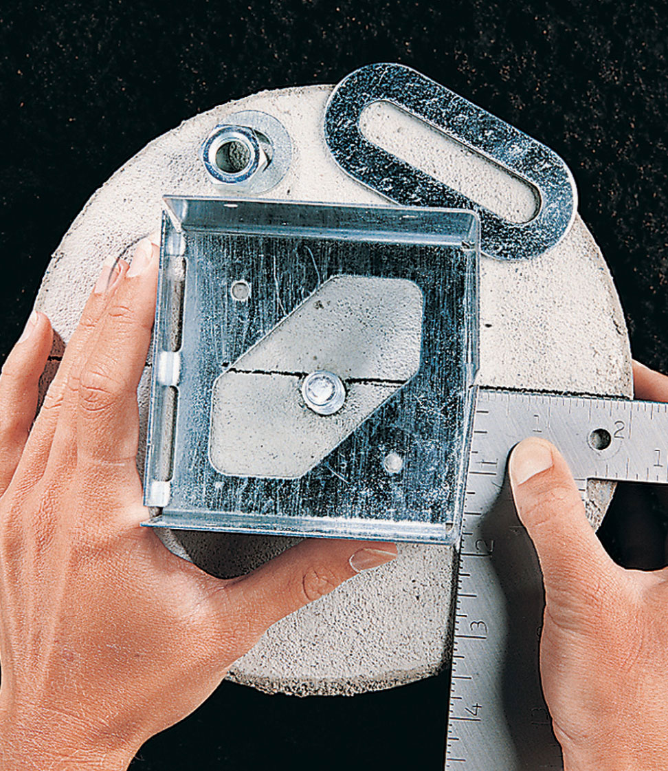
Square the post anchors to the reference lines on the top of each footing to ensure that the posts are aligned with each other.
Drill pairs of 3/8" pilot holes at 16" intervals through the ledger and into the house header joist. Counterbore each pilot hole 1/2", using a 1 3/8" spade bit. Attach the ledger with lag screws and washers, using a ratchet wrench.
Apply a thick bead of silicone caulk between siding and flashing. Also seal lag screw heads and the cracks at the ends of the ledger.
To locate the footings, drop a plumb bob from the end of the ledger down to a level that’s comfortable for making measurements and stretching mason’s strings.
Measurements for the footing centerpoints are shown on the Framing Plan (page 316). Construct, position, and install temporary 2 × 4 batterboards.
Stretch three strings perpendicular to the house; one at each end of the ledger, and one at the centerline of the footing for the secondary beam, 80-1/4" from the right end of the ledger.
Make sure that the strings are square to the house by using the 3-4-5 triangle method. Measuring from the point where the string meets the house, make a mark on the house at 3 ft. Then measure out along the string and make a mark at 4 ft. When the string is truly perpendicular, the diagonal line connecting the two marked points will measure 5 ft. Adjust the string on the batterboard as needed.
Stretch the fourth string between batterboards, parallel to the house, at the centerline of the primary beam.
Measure along the parallel string and use tape to mark the three centerpoints of the footings for the primary beam.
To locate the footing for the secondary beam, use tape to mark a point on the middle perpendicular string that is 48-3/4" out from its intersection with the parallel string.
Transfer the locations to the ground by dropping a plumb bob from each tape mark and driving a stake into the ground at each point.
Remove the mason’s strings and dig holes for the footings, using a clamshell digger or power auger. Pour 2" to 3" of loose gravel into each hole for drainage.
Note: When measuring the footing size and depth, make sure you comply with your local building code, which may require flaring the base. Cut the footing forms to length using a reciprocating saw or handsaw, and insert them into the footing holes, leaving 2" of tube above ground level. Pack soil around the forms for support, and fill with concrete, tamping with a long stick or rod to eliminate any air gaps.
Screed the tops flush using a straight 2 × 4. Insert a J-bolt into the center of each footing, leaving 3/4" to 1" of thread exposed. Retie the mason’s strings and use the plumb bob to position the J-bolts at the exact center of each footing. Clean the bolt threads before the concrete sets.
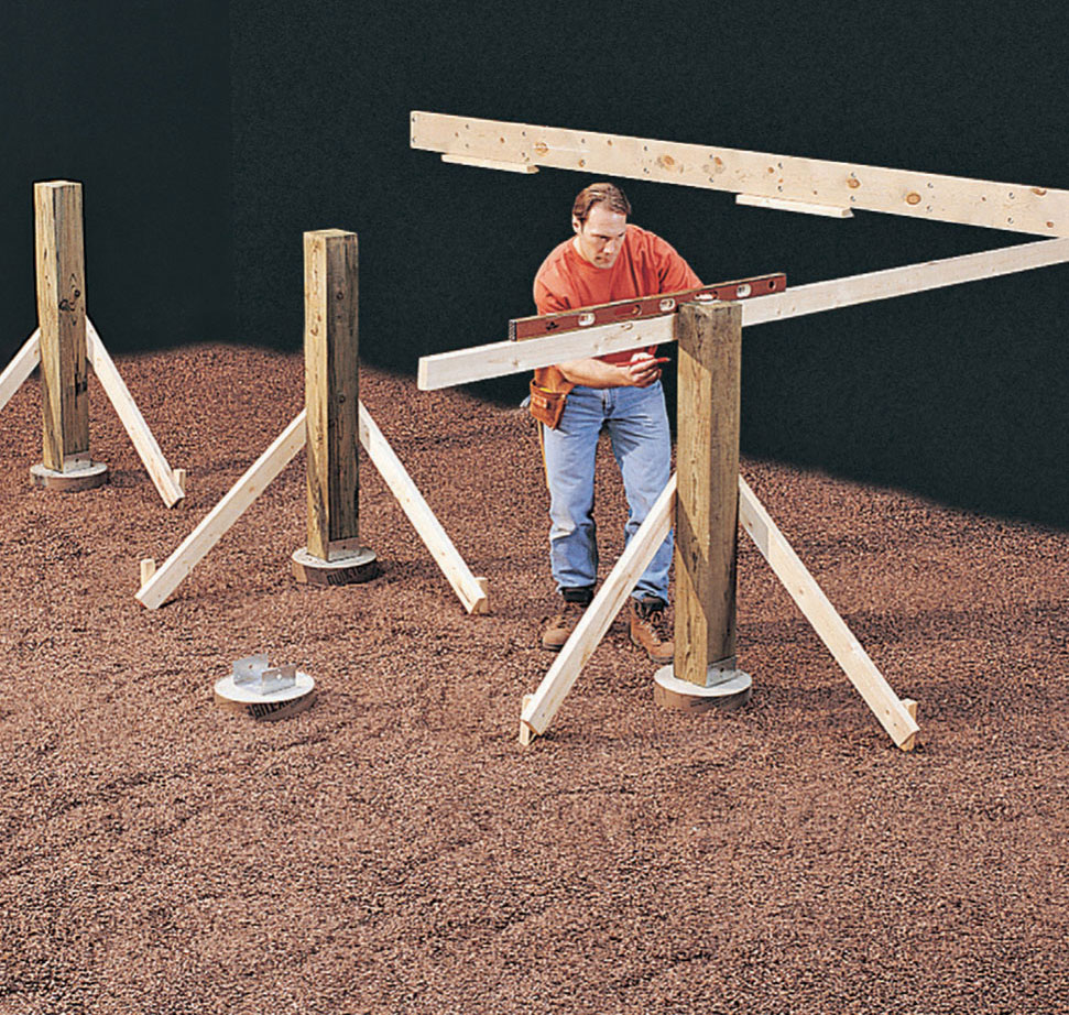
Determine the finished post height by leveling a straight 2 × 4 from the bottom edge of the ledger.
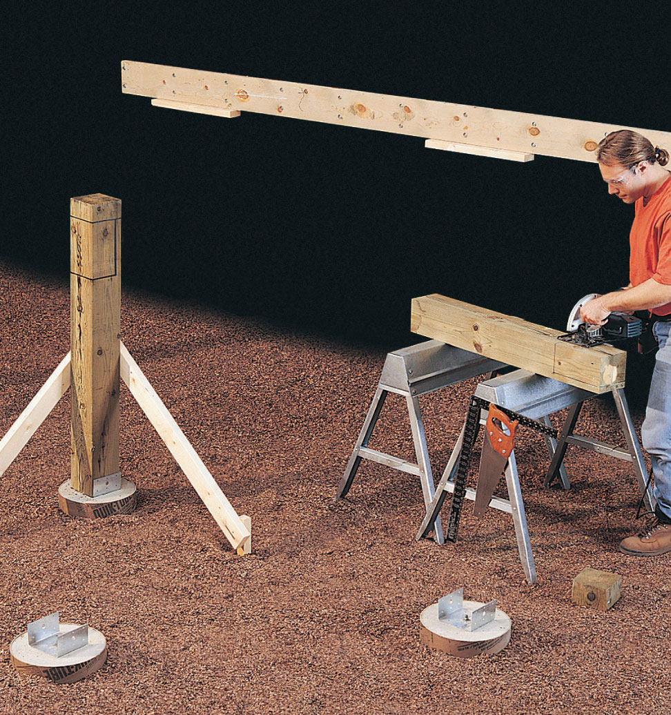
After marking the notches for the primary beam, cut out the tops of the posts with a circular saw and a handsaw.
To provide a reference line for orienting the post anchors so the posts will be aligned with each other, lay a long, straight 2 × 4 flat across the primary beam footings, parallel to the ledger. With one edge tight against the J-bolts, draw a line across the top of each footing.
To mark the post anchor position on the footing for the secondary beam, mark a line across the footing at a 45° angle to the primary beam.
Place a metal post anchor on each footing, centering it over the J-bolt and squaring it with the reference line. Thread a nut over each J-bolt and securely tighten the post anchors in place.
Estimate the height of each post, and cut the posts slightly long to allow for final trimming. Set the posts in the anchors and tack into place with one nail.
With a level as a guide, use braces and stakes to ensure that the posts are plumb.
Determine the top of the posts by extending a straight 2 × 4 from the bottom edge of the ledger and marking a line on the posts level with the bottom of the ledger.
Outline a 4-1/2 × 9 1/4" notch (see Post Detail, page 317) at the top of each of the primary-beam posts.
Remove the posts from the anchors, cut to finished height, and cut the notches using a circular saw and handsaw.
Reposition the posts with the notches facing away from the house, brace them plumb, and nail them securely to the post anchors.
We used 20 ft. boards for the primary beam. However, for reasons of cost or availability, you may need to use a smaller size. Check with your local building inspector regarding acceptable joining hardware and techniques.
Construct the primary beam from 2 × 10" boards. Position the primary beam boards (C) so the crowns face the same direction, and fasten together with 16d galvanized nails. Drill pairs of 3/8" holes through the beam at 24" intervals, and secure with carriage bolts, washers, and nuts.
Measure, mark, and cut the beam to length. Position the beam in the post notches, crown side up. Make sure the beam is square to the ledger by measuring the diagonals; adjust the beam position so the diagonal measurements are equal.
Drill two 3/8" pilot holes through each post into the beam. Fasten with lag screws and washers, using a ratchet wrench.
Measure, mark, and cut the post for the secondary beam slightly long to allow for final trimming. Install the post in the post anchor.
Locate and mark the points where the secondary beam butts against the primary beam. Run a straight 2 × 4 across the face of the post to the primary beam in both directions. Outline the ends of the secondary beam on the face of the primary beam, and install 45° 2 × 10 double joist hangers at each point.
Measure, mark, and cut secondary beam boards (D) to length, using a circular saw.
Install the boards one at a time, verifying that they are level and attaching them with deck screws.
Drill pilot holes through the assembled beam and into the post. Counter-bore the holes 1/2" deep with a 1 3/8" spade bit, and secure the secondary beam to the post with lag screws.
Fasten the secondary beam to the joist hangers with 10d galvanized joist hanger nails.
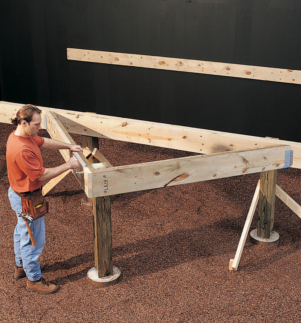
After the secondary beam boards have been cut, assembled, and attached with deck screws, secure the beam to the post with lag screws.
Measure and cut the end joists (E), leaving them several inches long for final trimming. Install by nailing into the ends of the ledger with 16d galvanized nails and toenailing to the top of the primary beam.
The joists are not all evenly spaced. Referring to the Framing Plan (page 316) use a combination square and draw the joist outlines on the face of the ledger and the top of the beams.
Install a joist hanger on the ledger at each location. Attach one flange of a hanger to one side of each outline, using joist hanger nails. Use a spacer cut from scrap 2 × 10" lumber to achieve the correct spread for each hanger, then fasten the remaining side flange with joist hanger nails. Remove the spacer and repeat the procedure to install the remaining joist hangers.
Measure, mark, and cut the joists (G), using a circular saw. Be sure to leave the joists long to accommodate final angled trimming. Place joists in hangers with crown side up and attach with nails. Align joists with the outlines on the top of the beam and toenail in place.
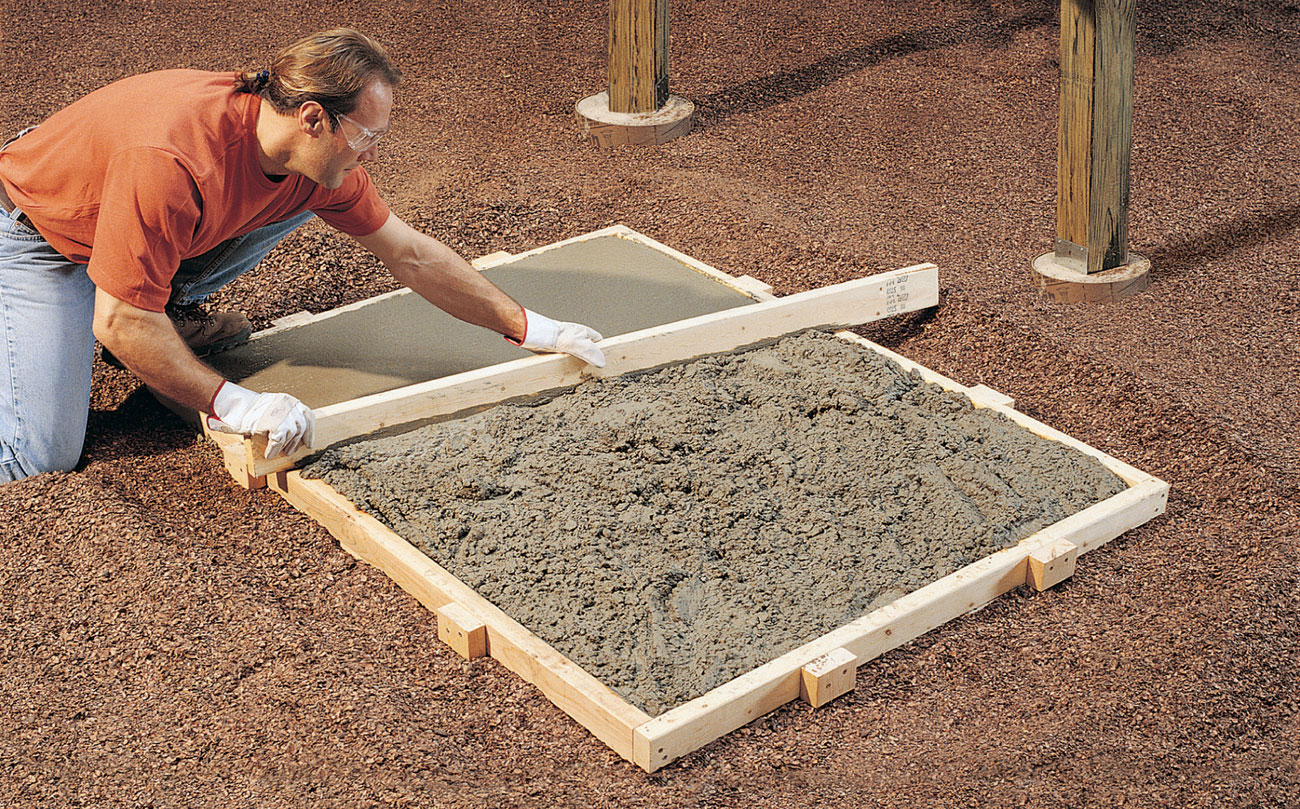
Pour the concrete into the staircase pad form, and screed flush, using a straight 2 × 4. Note: Be aware that most building codes prohibit the securing of deck staircases to a solid concrete pad. You may need to pour individual footings for the staircase bottom posts.
Snap chalk lines along the top edges of the joists (see Framing Plan, page 316) to mark the perimeter of the deck. All the angles are either 45° or 90°. Allow for the 1 1/2" thickness of the rim joists. Extend the cutoff lines to the faces of the joists, and make the cuts using a circular saw.
Referring to the Framing Plan and confirming the actual dimensions of your deck, measure, mark, and cut the rim joists (F) to size and attach them to the joists with deck screws.
Locate railing posts in the corners of the deck, then center the intermediate posts between them (see Framing Plan, page 316).
Cut railing posts (H) to length (see Railing Detail, page 317). Cut a 60° pyramid on the top of each post, and rout a 1/2 × 1/2" groove on all four sides 1" below the pyramid.
To install the railing posts, clamp them one at a time into position, and drill 1/4" pilot holes through the rim joist into the post. Counterbore the holes 1/2" using a 1" spade bit, and secure the posts to the rim joists with lag screws.
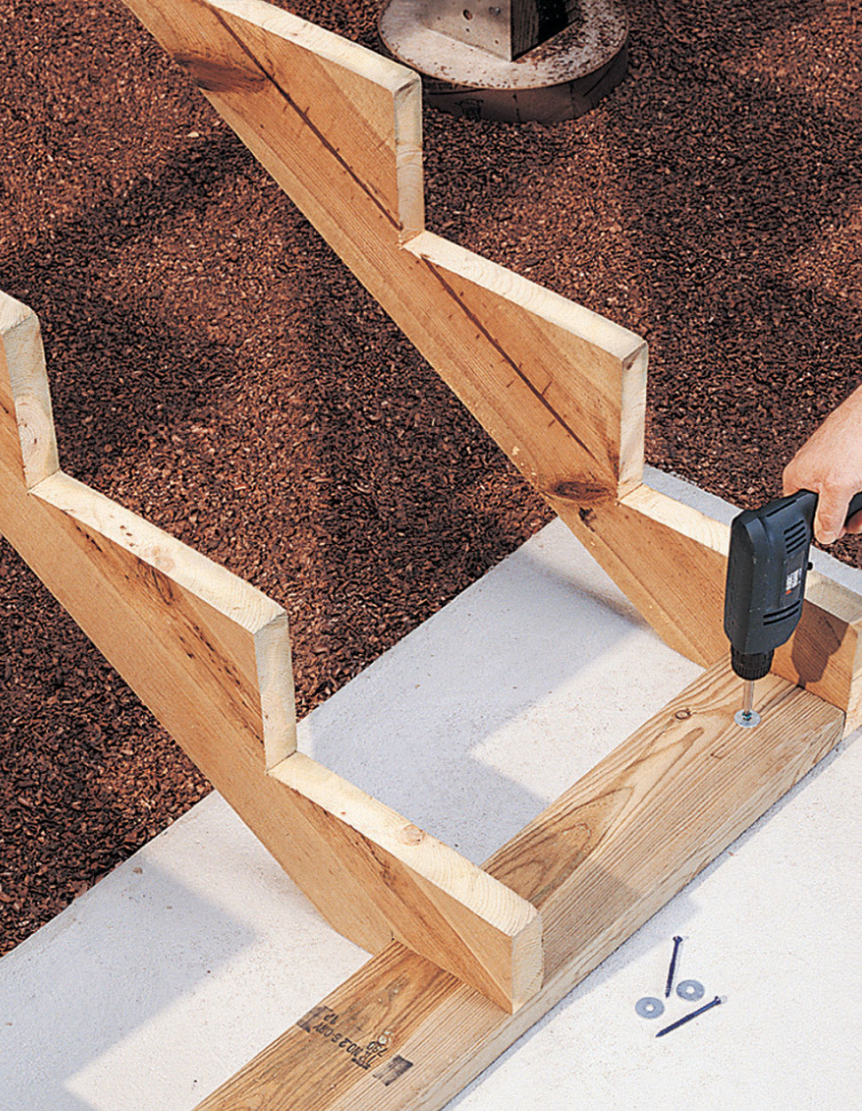
Drill pilot holes through the gusset and into the concrete pad, then attach with masonry screws using a power drill.
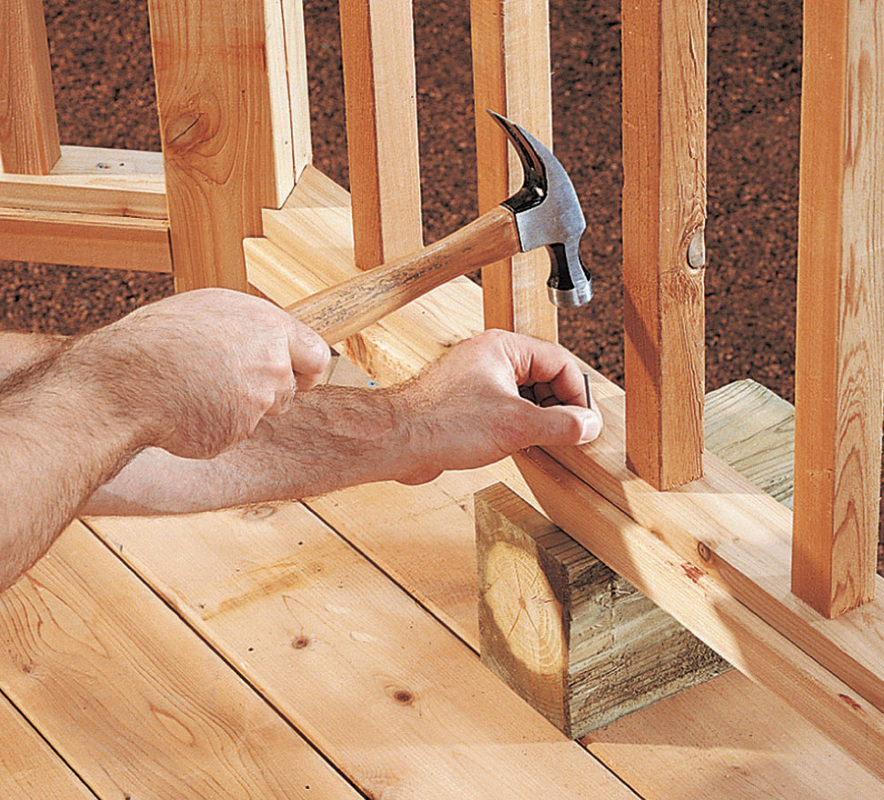
Use a nailing block to support the bottom rail, and attach the baluster assembly with nails. Notice the notch where the rails join the post at a 45° angle.
Determine the location of the concrete pad. Add 6" in each direction, and excavate approximately 8" deep.
Lay and tamp a 4" base of compactible gravel.
Build a form from 2 × 6 lumber, and align the inside of the form with the outside rim joists as shown in the Framing Plan, page 316. Level the form at 56" below the finished surface of the deck, to accommodate eight 7" stairway rises. Stake the form into place.
Fill the form with concrete, screed with a straight 2 × 4, and let the concrete set up overnight. Note: Most building codes now prohibit securing a deck staircase to a solid concrete pad. You must check with your local building department to ensure your deck staircase adheres to prevailing standards and codes.
Lay out the stringers (I), according to the Stairway Detail, page 317. Notch the center stringer at the top and bottom to fit around the gussets. Mark the rises and runs with a framing square. Cut the notches with a circular saw, using a reciprocating saw or handsaw to finish the corners.
Measure, mark, and cut the gussets (J) to length. Assemble the stairway framework by nailing the gussets in place between the outer stringers with 16d nails. Turn the framework upside down and attach the center stringer by nailing through the gussets.
Position the stairway framework against the deck rim joist, and attach with deck screws driven through the top gusset into the rim joist. Drill pilot holes through the bottom gusset into the concrete pad and attach with masonry screws.
Cut the stair railing posts (K) to length. Shape the top ends. Install the posts by clamping them into place against the stringers, drilling pilot holes through the stringers into the posts, and attaching with lag screws and washers.
Measure and cut the treads (L) to length, using a circular saw. The bottom treads are notched to fit around the posts.
If possible, buy decking (M) long enough to span the deck. When joints between deck boards are necessary, center them above joists so the ends of both boards are supported.
Position the first deck board along the outer 45° rim joist, and mark the railing post locations. Cut notches for the railing posts, using a circular saw, handsaw, and chisel. Attach the board by driving two deck screws into each joist.
Cut and attach the remaining deck boards, leaving a 1/8" gap between the boards for drainage.
The railing for this deck is assembled in sections and then installed. The balusters are first fastened between the inner rails, then the baluster assembly is cut to exact length and attached to the outer rails.
Verify the measurements between your railing posts. Measure, mark, and cut the top and bottom rails (N) to length.
Install the bottom rails by drilling angled 1/8" pilot holes into the posts at the ends, and attaching with deck screws. Note: Where the railings meet the posts at a 45° angle, you’ll need to notch the ends to fit.
Measure, mark, and cut the top and bottom inner rails (O), leaving them several inches long for final trimming.
Measure, mark, and cut the deck balusters (P) to length.
Assemble each railing section by positioning the balusters between the top and bottom inner rails, drilling 1/8" pilot holes, and attaching them with deck screws. Trim the section to final length with an equal space at each end.
Position the baluster assembly on the bottom rail and nail in place.
Position the top rail above the baluster assembly, drill pilot holes through the top inner rail into the top rail, and attach with deck screws from below.
To determine the angle for the ends of the stairway rails and balusters, as well as the length of the inner and outer stairway rails, hold a straight 2 × 4 across one pair of stairway posts. With the top edge of the 2 × 4 crossing each post at the routed groove, mark the angle on the back of the board. Note: The angle will be approximately 32°, but you’ll get the best fit by marking it from your actual railing posts.
Measure, mark, and cut the top and bottom rails to length, with the ends angled to fit against the posts. Install the bottom rails.
Cut inner rails and balusters to size with mitered ends.
Build the stairway railing assemblies using the same procedures as used for the deck railing assemblies, taking care that the space between balusters is 4" or less.
Install the stairway railing assemblies by positioning them on the bottom rails and nailing with 6d casing nails.
Install the stairway top rails by positioning them above the railing assemblies, drilling pilot holes through the top inner rails, and driving deck screws from below.
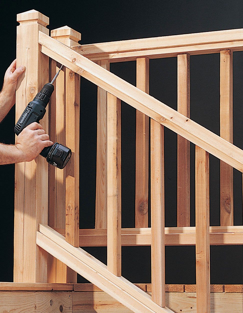
Drive deck screws up through the top inner rail to attach the top rail to the baluster assembly.
 Square Platform Deck
A freestanding platform deck is a low-maintenance option for creating an outdoor floor. Because it can be constructed virtually anywhere, in almost any size, a platform deck works in nearly any landscape. The wood can be left natural, stained, or painted to blend with your house and other landscape elements.
You’ll be able to build this deck over a single weekend. It uses lumber in standard lengths, so you won’t need to do a lot of cutting. In addition, this deck uses precast concrete footings rather than poured footings. These precast footings are available at home improvement centers and lumberyards.
This 12 × 12-ft. deck rests on a 10 × 10-ft. base formed by 18 concrete footings arranged in three rows of six footings each. Joists are secured in slots in the tops of the footings, simplifying the building process.
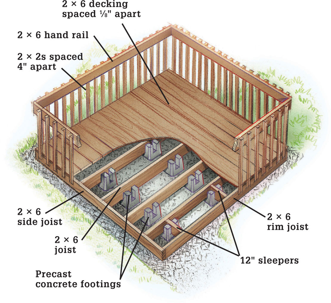
Framing Plan
Construction Materials
Precast concrete footings (18)
12-ft. 2 × 6s (38)
2 lbs. galvanized 3" deck screws
For optional railing:
42-in. 2 × 2s (75)
12-ft. 2 × 6s (4)
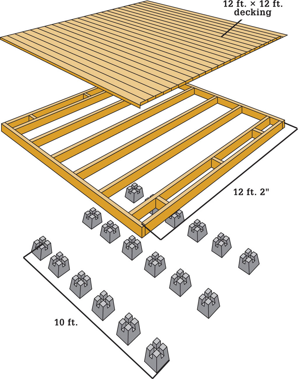
 How to Build a Platform Deck
Measure a 10 × 10-ft. area for the deck foundation, and mark the corners with stakes.
Position a footing at each corner, then measure from corner to corner, from the center of each footing. Adjust until the diagonal measurements are equal, which means the footings are square.
Place a 2 × 6 across the corner footings for the back row, setting it in the center slots. Check this joist with a level, then add or remove soil beneath footings as necessary to level it.
Center a footing between these corner footings.
Use a level to recheck the joist, then add or remove soil beneath the center footing, if necessary. Remove the joist.
Repeat the process to set and level the footings for the front row.
Position the remaining 12 footings at equal intervals, aligned in three rows. Position a 2 × 6 from the front row of footings to the back, and adjust soil as necessary to bring the interior footings into alignment with the front and back rows.
Seal the ends of each 2 × 6 with wood sealer/ protectant and let them dry completely.
Center a 12-ft. joist across each row of footings. Using a level, check the joists once again and carefully adjust the footings if necessary.
Line up a 2 × 6 flush against the ends of the joists along the left side of the deck, with the ends extending equally past the front and back joists.
Attach the side joist by driving a pair of deck screws into each joist.
Repeat this process to install the right side joist.
At the front of the deck, position a 2 × 6 rim joist flush between the ends of the side joists, forming a butt joint on each end.
Attach the rim joist to the side joists by driving a pair of deck screws through the faces of the side joists, into the ends of the rim joist.
Repeat to install the other rim joist.
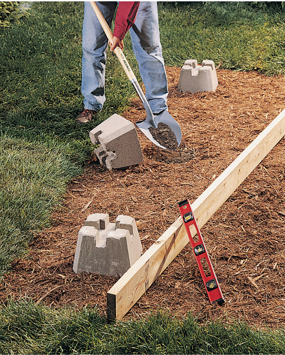
Position the corner footings and the center footing for the back joist. Remove or add soil beneath the footings to level them.
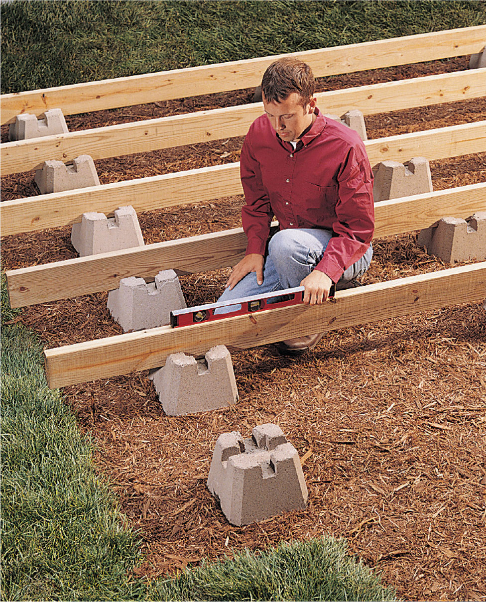
Position the remaining footings and insert the joists. Check to make sure the framework is level, and adjust as needed.
Measure and cut six 2 × 6 sleepers to fit between the front and back joists and the rim joists. Seal the cut ends with wood sealer/protectant and let them dry completely.
Position one sleeper in each row of footings, between the first joist and the rim joist. Attach each sleeper by driving a pair of galvanized deck screws through each of the joists and into the sleeper.
Once the framing is complete, measure the diagonals from corner to corner. Compare the measurements to see if they are equal.
Adjust the framing as necessary by pushing it into alignment. Have someone help you hold one side of the framework while you push against the other.
Seal the 2 × 6 decking boards with wood sealer/ protectant and let them dry. Seal all exposed framing members as well.
Lay a 2 × 6 over the surface of the deck, perpendicular to the joists and flush with the rim joist. Secure this board with deck screws.
Repeat to install the rest of the decking. Use a framing square to set a 1/8" space between boards. Rip cut the last decking board if needed.
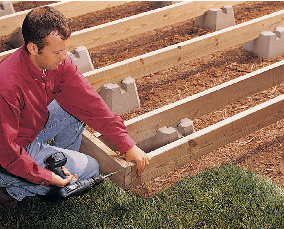
Install the front and back rim joists between the ends of the side joists, securing them with pairs of deck screws.
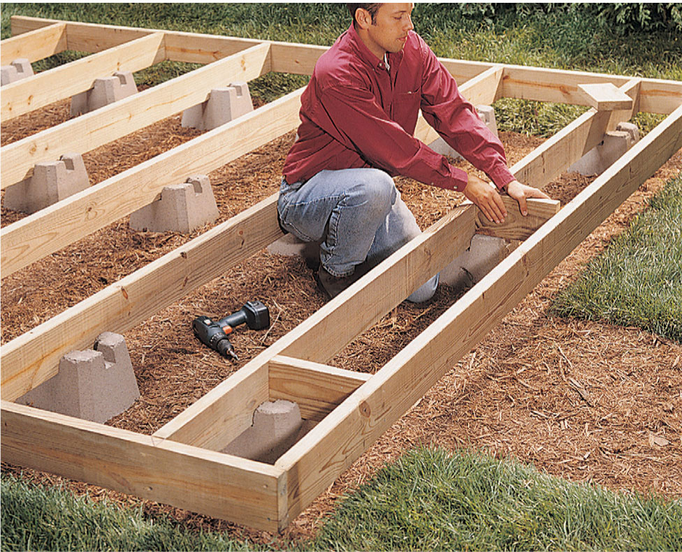
Position the sleepers in the slots of the footings, then attach them to both joists with pairs of deck screws.
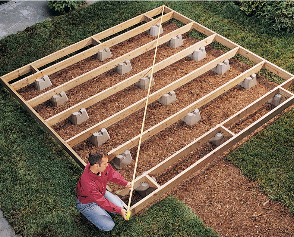
After the framing is completed, measure the diagonals and adjust the frame until it’s square.
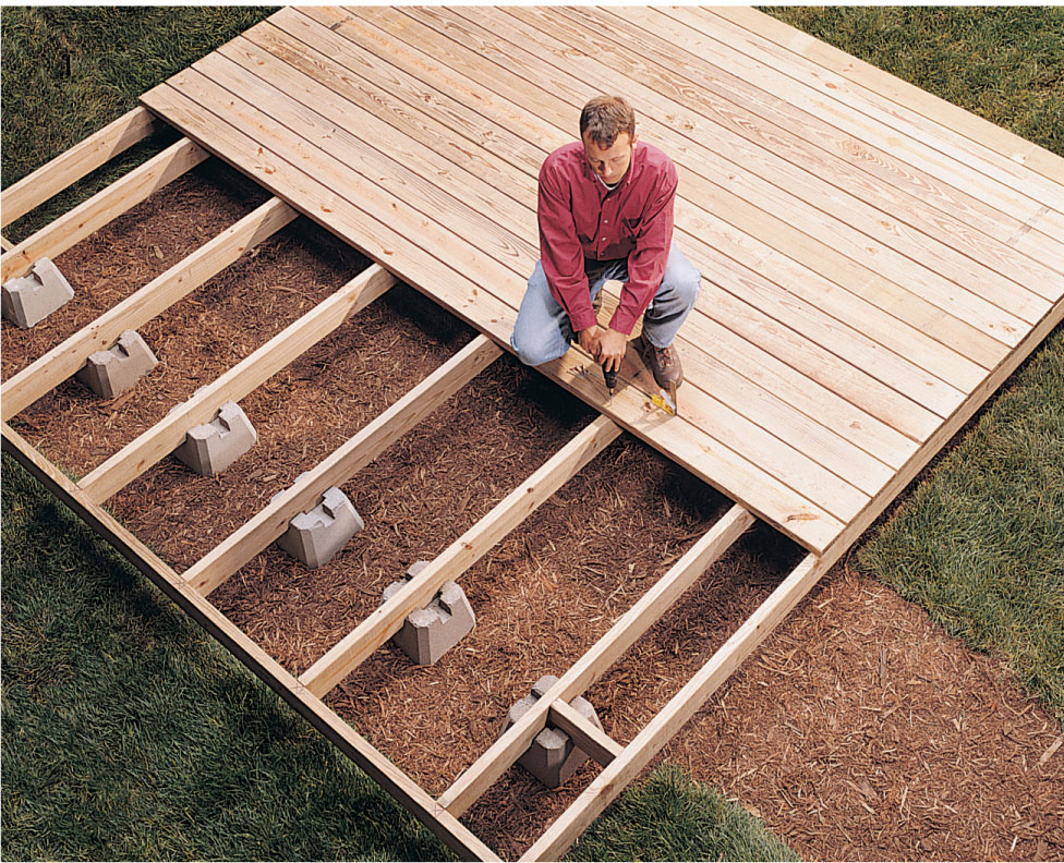
Install the decking by driving a pair of screws into each joist. Use a framing square to leave a 1/8” space between boards.
 Multi-level Deck
This multilevel deck is ideal where you need access from different areas and levels of your home. The size and shape also provide many functional spaces for entertaining, privacy, or relaxation, as well as unobtrusive storage areas for recreational accessories.
The lower deck in this plan has been built around a patio. If you want this as a deck area instead, simply extend the lower ledger board across the house and run joists between the ledger and the center beam. You can remove the spa area from the plans and adjust the shape of the lower deck if you wish, too.
With some modification, this design also can help you make use of an otherwise unusable steep slope. However, you may need to eliminate or reduce the storage and small deck area underneath the landing. Some excavation of the existing slope area might also be required.
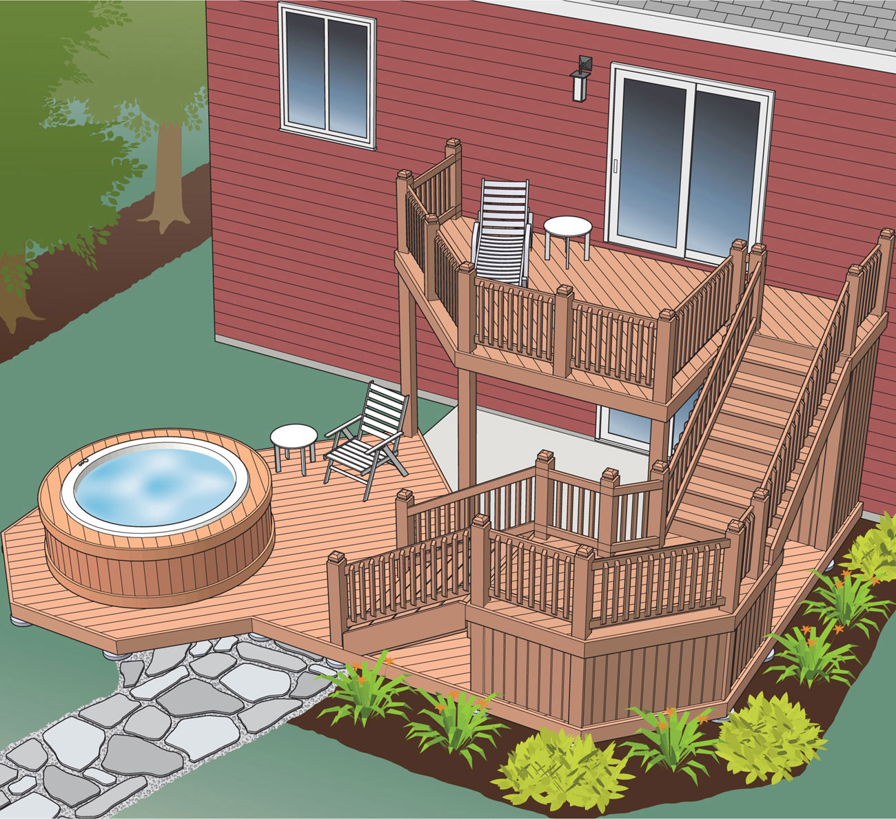
A large, multi-level deck such as this is ideal where you want to include many different recreation areas, such as an outdoor dining spot, a reading corner, and a spa retreat. Add a privacy fence for an even more secluded tubbing experience.
Cutaway View: Lower Deck & Tub
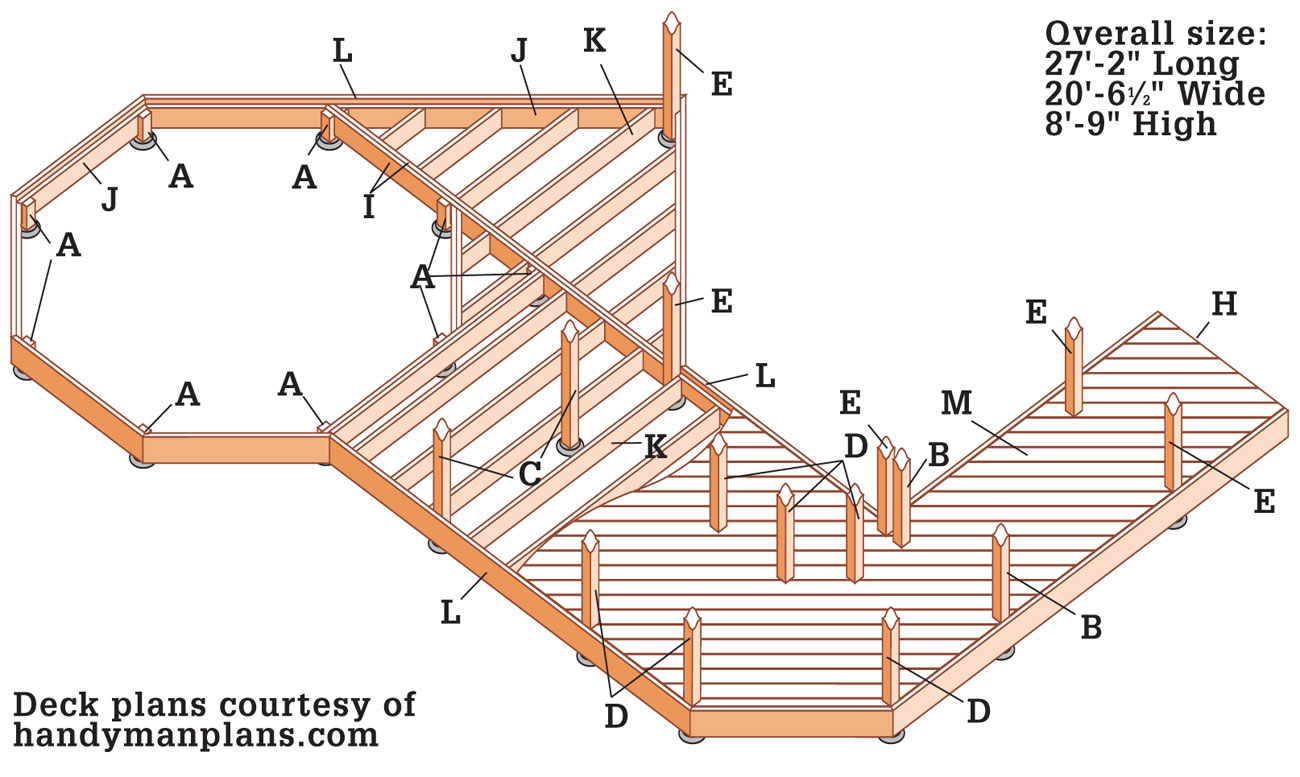
Supplies
2 × 6" metal joist hangers (138)
2 × 6" double metal joist hangers (2)
6 × 6" metal post anchors (28)
16d galvanized nails (3 1/2", 25 lbs.)
10d galvanized nails (3", 30 lbs.)
3" galvanized screws (15 lbs.)
60 lb. dry concrete in bags (62)
1/2 × 6" galvanized carriage bolts, washers, and nuts (26)
1/2 × 4" galvanized lag screws (26)
1/2 × 6" galvanized lag screws (12)
1/2 × 4" galvanized expansion bolts (8)
Weather-resistant hinges* (4)
Weather-resistant door latch* (2)
Metal ledger flashing (34 ft.)
Decorative post cap* (19)
*optional
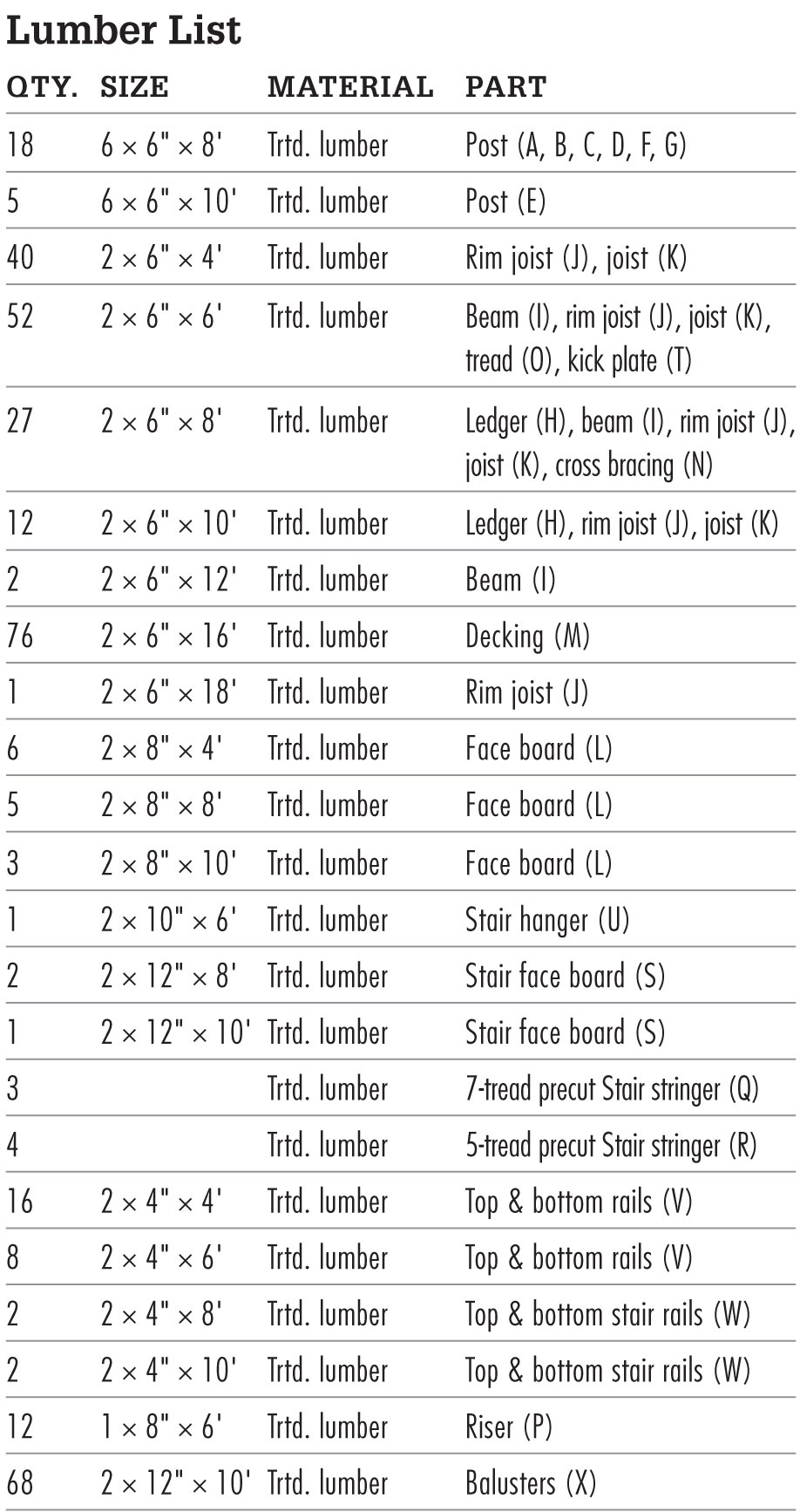
Front Elevation
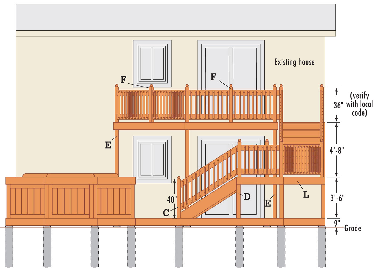
Upper Stair Detail
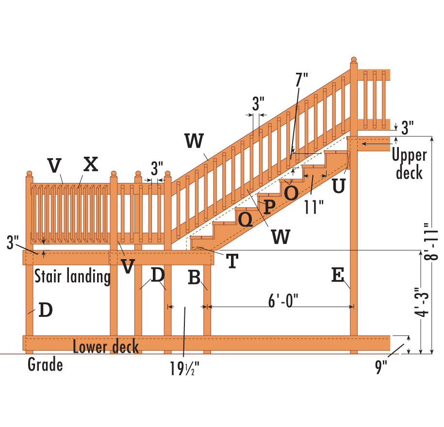
 How to Build a Multi-level Deck
Draw a level outline on the siding in both locations to show where the ledgers and the end joists will fit against the house (See the Lower Deck Framing Plan and Upper Deck Framing Plan, pages 331 and 332). Position the top edge of each ledger so that the surface of the decking boards will be 1" below the indoor floor level. This height difference prevents rainwater or melted snow from seeping into the house.
Cut out the siding along the outline with a circular saw. To keep the blade from cutting too deeply into the sheathing underneath the siding, set the blade depth the same thickness as the siding. Finish the corners of the cutouts with a hammer and chisel, holding the beveled side in to ensure a straight cut.
Install new building felt over the existing felt exposed by siding removal. Cut galvanized flashing to the length of each cutout using metal snips, and slide it up under the siding.
Measure and cut the ledgers to length from pressure-treated 2 × 6 lumber. Center the ledgers in the cutouts, underneath the flashing, with space at the ends for the end joists. Brace ledgers in place, fastening them temporarily to the house with 3" deck screws.
Drill pairs of 3/8" pilot holes through the ledger and sheathing and into the house header joist at 16" intervals. Counterbore each pilot hole 1/2" deep, using a 1 3/8" spade bit. Attach the ledgers to the wall with 1/2 × 4" lag screws and washers, using an impact driver or a ratchet wrench.
Apply a thick bead of silicone caulk between the siding and the flashing. Also seal the lag screw heads and any gaps between the wall and the ledgers.
Referring to the Post Location Plan on page 333, stretch mason’s strings across the site, using 2 × 4 batterboards. Check the mason’s strings for square, using the 3-4-5 triangle method. Adjust as necessary until they are square. Measure along the strings to locate the centerpoints of the footings. Mark the locations with tape.
Drop a plumb bob at the tape locations and drive stakes into the ground to mark the centerpoints of the footings. Remove the mason’s strings and dig holes for the footings, using a clamshell digger or power auger. Make certain the hole sizes and depths comply with your local building code, which may require flaring the footings at their base.
Pour 2" to 3" of loose gravel into each hole for drainage. Cut the footing tube forms to length, long enough so they will extend 2" above grade, using a reciprocating saw or handsaw. Insert the forms into the holes and backfill with soil. Lay out and mark the location for a concrete pad within the hexagonal spa area (see Lower Deck Framing Plan, page 331). Excavate and build forms for the pad.
Fill the tube forms with concrete in stages, tamping the concrete at each stage with a long stick to eliminate any air pockets. Screed the tops flush with a flat 2 × 4. Retie the mason’s strings and drop a plumb bob to establish centerpoint of the footing. Insert a J-bolt into each footing, leaving 3/4" to 1" of thread exposed. Clean the bolt threads before the concrete sets.
Pour concrete into the spa pad form and tamp to remove air pockets. Screed the top flush with the form (no other finishing techniques are necessary for this pad) and allow the pad to cure. Note: Some codes do not allow securing a portion of a deck connected to stairs to a concrete pad. Check your local building code.
Lay a long, straight 2 × 4 flat across pairs of footings. With one edge tight against the J-bolts, draw a reference line across each footing. Do this in both directions for pairs of footings where necessary.
Place a metal post anchor on each footing, center it over the J-bolt, and square it with the reference line. Thread a nut over each J-bolt and tighten each of the post anchors in place.
Cut deck support posts A through E to their approximate length, adding several inches for final trimming (see Elevation, page 332, and Upper Stair Detail, page 334). Place the posts in the anchors and tack them into place with one nail each.
With a level as a guide, plumb the posts, using braces and stakes to hold posts B through E plumb. Once the posts are plumb, finish nailing them to the anchors.
Using a string, water, or laser level, mark the top edge of the lower deck rim joists and center beam locations on posts A and at the footing ends of appropriate posts B through E (see Lower Deck Framing Plan, page 331). Make a mark level with the top edge of the lower ledger.
Mark posts E for the upper deck rim joists, using the top edge of the upper ledger as the reference.
Measure, cut, and install rim joists for the upper deck from pressure-treated 2 × 6 lumber. Do this one piece at a time to ensure accurate measuring. Cut 45° miters at the ends of the pieces that meet posts at the 45° corners. Attach rim joists to the post faces, using 3 1/2" deck screws.
Measure, cut, and install face boards from pressure-treated 2 × 8 lumber. Do this one piece at a time, as with the rim joists. Cut 22-1/2° miters at the ends of the pieces that meet at the 45° corners. Attach face board pieces that fit flush with the post faces using 1/2 × 6" carriage bolts, washers, and nuts. Attach pieces that don’t fit flush with the post faces at the 45° corners with 1/2 × 4" lag screws and washers. Make sure to stagger the bolt and/or screw locations on posts where two pieces attach. Attach the face boards to the rim joists with pairs of 3" deck screws driven at 24" intervals.
Build the center beam from doubled 2 × 8 pressure-treated lumber. Measure, cut, and attach it to the posts with 1/2 × 8" carriage bolts, washers, and nuts. Cut 45° miters in the ends of the pieces that will meet the rim joist face at a non-perpendicular junction.
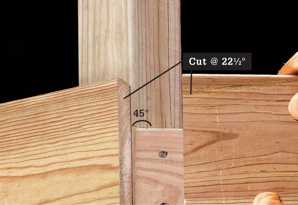
Cut 45° miters at the ends of rim joists that meet posts at a 45° corner. Cut 22-1/2° miters at the ends of face boards that meet at a 45° corner.
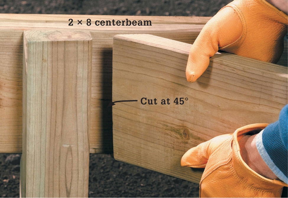
Cut a 45°-miter at the ends of rim joists and face boards that meet the center beam of the lower deck at a 45° corner.
Measure, cut, and install the rim joists and face boards for the lower deck in the same manner you followed for the upper deck. However, cut 45° miters in the ends of the pieces that will meet the center beam face at a non-perpendicular junction. Cut the tops of posts A flush with the top edges of the rim joists and center beam using a reciprocating saw.
Measure 42" up from the top of the lower deck rim joists attached to posts B and D and mark the posts (see Upper Stair Detail, page 334).
Measure, cut, and attach the landing rim joists, aligning their top edges with the 42" marks, and add the face boards in the same manner you followed for the lower and upper decks. Cut the tops of posts B flush with the top edges of the rim joists.
Measure and mark the outlines for joist locations spaced 16" on center on the ledger and rim joists of the upper deck (see Upper Deck Framing Plan, page 332). The spacing of the joists measured along the 45° angled rim joist will be 22-5/8" on-center. Measure and mark the outlines for joist locations for the stair landing.
Measure and mark the outlines for joist locations spaced 16" on center on the ledger, rim joists, and center beam of the lower deck (see Lower Deck Framing Plan, page 331). The joist spacing will be 22-5/8" on-center measured on the 45° angled rim joist.
Attach the joist hangers to the ledgers, rim joists, and center beam with 10d joist hanger nails, using a scrap 2 × 6 as a spacer to maintain the correct spread for each hanger. Use 45° joist hangers of the proper direction where joists meet the angled rim joists.
Measure, mark, and cut 2 × 6 pressure-treated lumber for the joists.
Insert the joists into the hangers with crown side up, and attach at both ends with 10d joist hanger nails. Be sure to drive a nail in every hole in the hangers. Add cross bracing for the joists in the upper deck as necessary.
Cut railing posts F and G to their approximate length, adding several inches for final trimming.
Clamp each post in place to the inner face of the rim joist. Drill pilot holes for two 1/2 × 6" carriage bolts through the rim joist and the post. Counterbore the holes in the rim joist 1/2"-deep, using a 1 3/8" spade bit. Attach the posts to the rim joists with the carriage bolts, washers, and nuts.
Position a deck board along the outer 45° rim joist on the upper deck, overhanging the rim joists at both ends. Mark the railing post locations.
Cut notches for the railing posts, using a jigsaw. Test fit the board: its leading edge should be flush with the front face of the 45° rim joist. Adjust as necessary. Attach the board by driving two deck screws into each joist.
Cut and attach the remaining deck boards, again letting ends overhang the rim joists. Leave a 1/8" gap between the boards for drainage. Cut notches for railing posts.
Mark and snap lines across the overhanging board ends that are aligned with the outer faces of the rim joists. Set the depth of the circular saw blade 1/8" deeper than the thickness of the decking and cut along the line, and complete cuts at corners or walls with a jigsaw, and a hammer and sharp chisel. Remove all braces and stakes supporting posts. Install the decking on the stair landing and lower deck following the same methods.
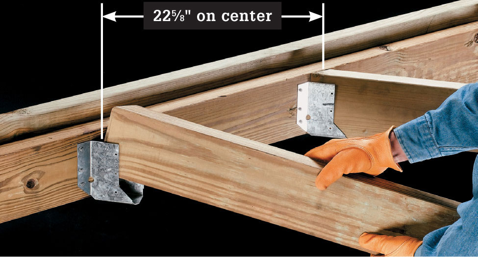
Use 45°-angled joist hangers where joists meet the angled rim joists. Space joists 22-5/8" on center.
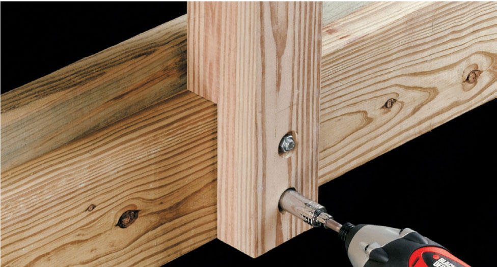
Attach the railing posts to the upper deck rim joists with carriage bolts, washers, and nuts. Note: check your local codes; most codes now prohibit notched railing posts. You may have to adjust the plans to mount the post entirely on the outside of the rim joist.
Cut the stair stringers for the upper stairs to length and use a framing square to mark the rise and run for each step. (See Upper Stair Detail, page 334. If you need to alter the plans to accommodate the height of your deck, see pages 146 to 149.) Cut the notches and the angles at the ends of the stringers with a circular saw, then complete the cuts at corners with a jigsaw.
Measure and cut a stair hanger and attach it to the posts E at the stair location with deck screws. Its top edge should butt against the bottom edge of the rim joist.
Position the middle stringer so the bottom end is flat against the middle of the stair landing and the upper end is against the stair hanger. Mark where the front edge of the stringer meets the landing. Measure and cut a 2 × 6 kick plate to fit between the outer stringers. Align the front edge of the kick plate with the mark so the board is parallel to the near edge of the landing. Fasten with deck screws. Cut a notch for the 2 × 6 kick plate in the middle stringer.
Position each outer stringer against one end of the kick plate and against the stair hanger. Drive a screw through each stringer into the kick plate. Square each stringer to the hanger, using a framing square, and mark its position. Attach the upper ends of the stringers to the hanger with angle brackets. Position the middle stringer evenly between the outer stringers. Attach it to the stair hanger with a skewable joist hanger, and to the kick plate using deck screws driven at an angle.
Measure and cut riser boards from pressure treated 1 × 8 lumber. Attach the riser boards to the stringers with two deck screws per stringer. Drill pilot holes for the screws at the ends of the boards.
Measure and cut two 2 × 6 stair treads for each step. Their ends should be flush with the outer faces of the stringers. Attach the treads with two deck screws per tread at each stringer, leaving a 1/8" gap between treads. The back tread should touch the riser on each step.
Measure, layout, cut, and install the lower stairs following the same methods.
For railing installation, refer to the Upper Stair Detail on page 334. For additional railing installation techniques, refer to pages 161 to 191.
Install the spa on the pad and connect it to the utilities following the manufacturer’s instructions. Have a professional do the installation if you are not comfortable working on plumbing, wiring, or gas systems.
After the spa is installed, follow the methods on pages 266 to 269 for enclosing the framing. You can use the same basic techniques to create storage enclosures beneath the stairway landings.
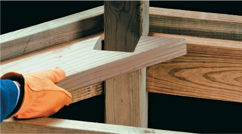
Cut notches in the decking boards that meet the railing posts. Test fit the board: the leading edge should be flush with the face boards.
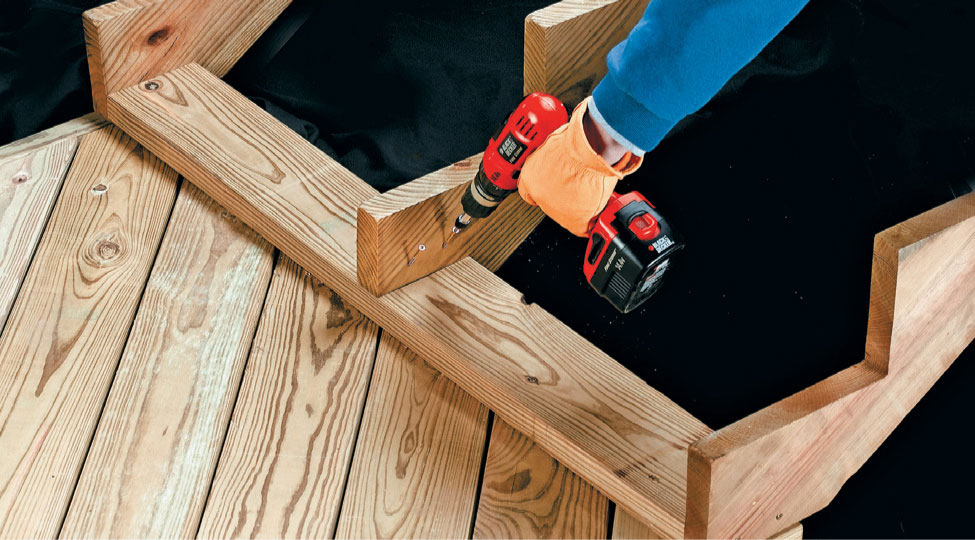
Attach the center stair stringer to the kick plate, using deck screws driven at an angle.
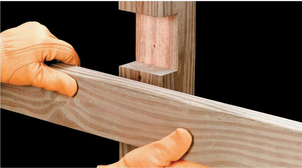
Cut and install railings in notches cut into the inner faces of the railing posts.
 Casual Curve Deck
Gentle, sweeping curves define this delightful design. Enclosed wraparound steps give a feeling of solidity to the deck. Easily adapted to other dimensions, this plan offers a great deal of functional appeal without a large outlay of time or money. The deck pattern is a simple “flying V” design that also adds enormous visual interest.
Stair railings should not be necessary with the height and step design of this plan, but check with your local building inspector. A simple metal railing could be installed without affecting the visual allure of the design. A built-in planter and matching bench provide both increased function and greater aesthetic appeal to what is a very simple deck design.
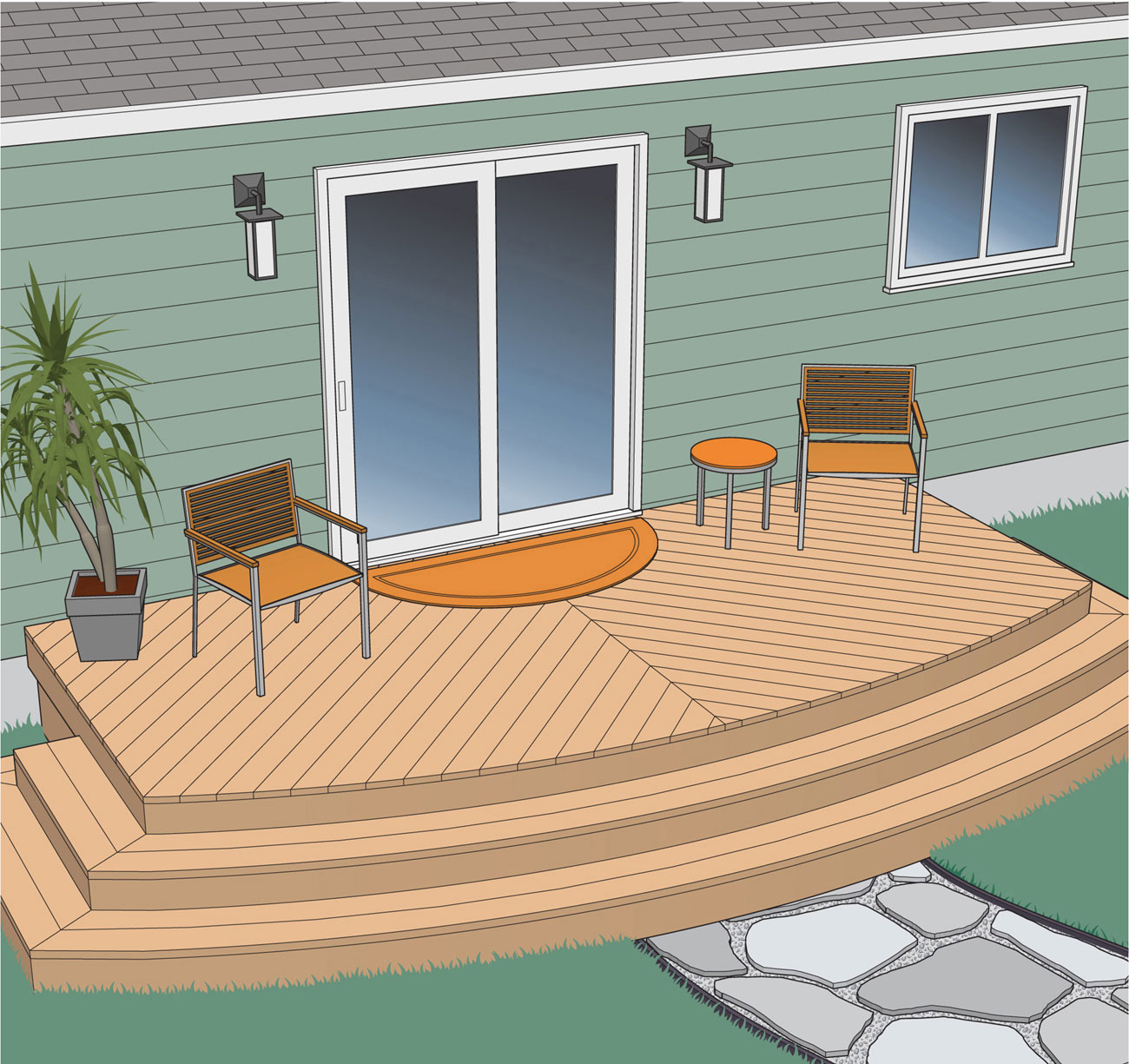
This small deck is basic in design but still very stylish due to the enclosed steps. They make the deck appear as a solid structure. The deck itself is made even more interesting with the flying V pattern of the deck boards.
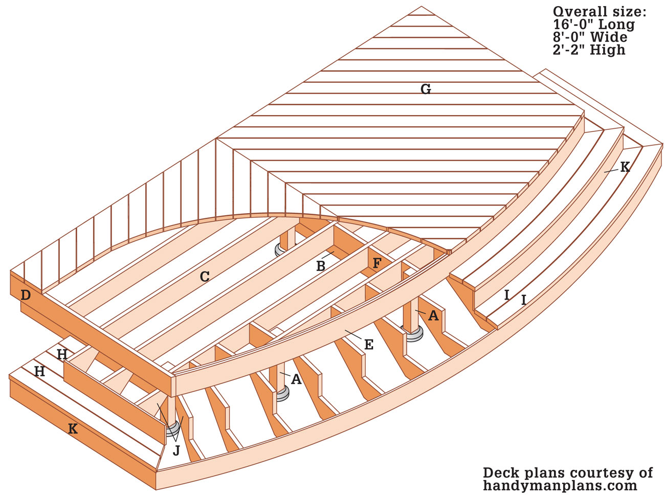
Supplies
10"-diameter footing forms (9)
3" direct bearing hardware (6)
2 × 8" double joist hangers (4)
2 × 8" joist hangers (72)
2-1/2" decking screws
Joist hanger nails
16d galvanized nails
12d galvanized casing nails
1/2 × 4" carriage bolts, washers, and nuts (12)
1/2 × 4" lag screws (22)
Exterior silicone caulk (3 tubes)
Concrete as required
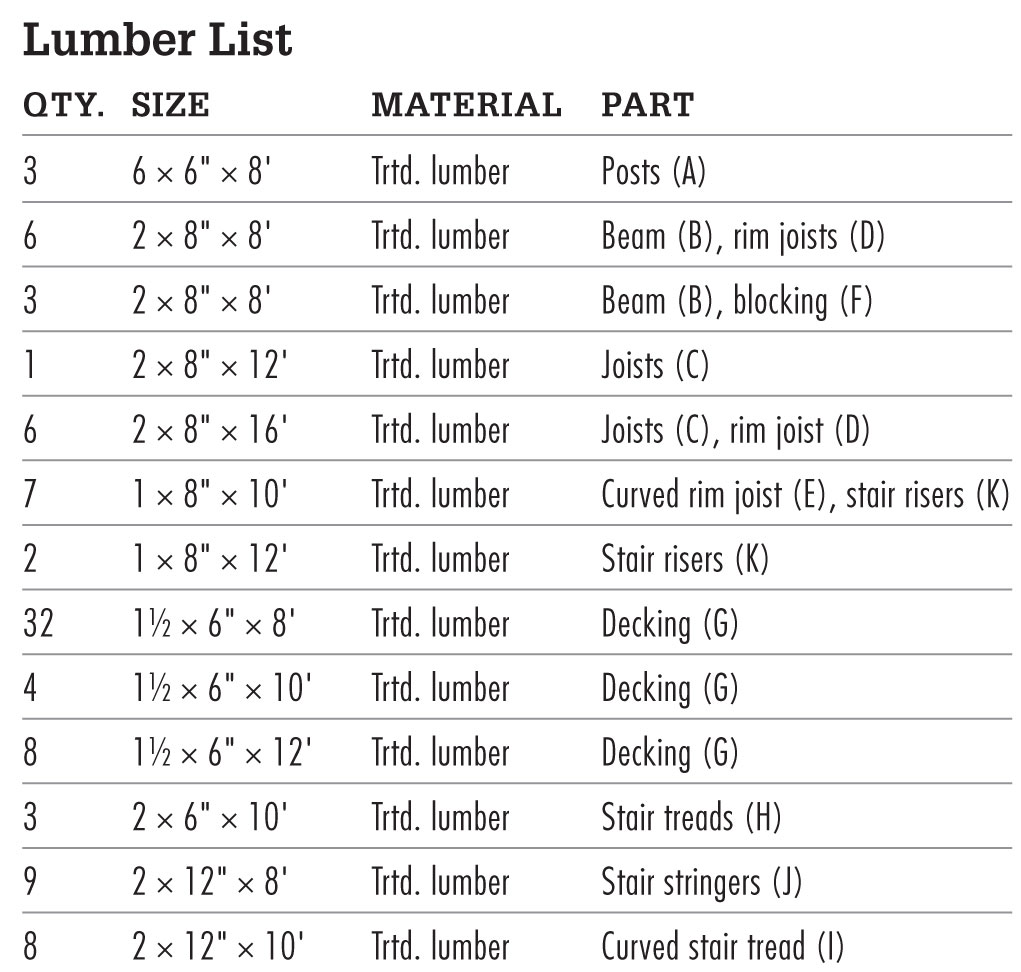
 How to Build a Casual Curve Deck
A ledger isn’t used for this deck plan. If you alter these plans to include a ledger board, see pages 62 to 69 for ledger installation methods.
Mark the deck location on the wall of the house (see Framing Plan), then stretch mason’s strings across the site, using 2 × 4 batterboards. Temporarily attach batterboards to the wall with deck screws. Check the mason’s strings for square, using the 3-4-5 triangle method. Adjust as necessary until they are square. Measure along the strings to locate the centerpoints of the footings and mark each with tape. Note: Allow yourself room to dig the footings at the house wall; the centerpoint of the posts can be up to 16" from the end of the beam.
Drop a plumb bob at the tape locations and drive stakes into the ground to mark the centerpoints of the footings.
Remove the mason’s strings and dig holes for the footings, using a clamshell digger or power auger. Make certain the hole sizes and depths comply with your local building code, which may require flaring the footings at their base.
Pour 2" to 3" of loose gravel into each hole for drainage.
Cut the footing tube forms to length, so they extend 2" above grade, using a reciprocating saw or handsaw. Insert the forms into the holes and backfill with soil.
Fill the tube forms with concrete in stages, tamping the concrete at each stage with a long stick to eliminate any air pockets. Screed the tops flush with a flat 2 × 4.
Retie the mason’s strings and drop a plumb bob to establish the centerpoint of the footing. Insert a J-bolt into each footing, leaving 3/4" to 1" of thread exposed. Clean the bolt threads before the concrete sets. Note: Another option is to install threaded rods with epoxy after the concrete has cured.
Start by laying a long straight 2 × 4 flat across pairs of footings. With one edge tight against the J-bolts, draw a reference line across each footing. Do this in both directions for pairs of footings where necessary.
Place a metal post anchor on each footing, center it over the J-bolt, and square it with the reference line. Thread a nut over each J-bolt and tighten each of the post anchors in place.
Cut 30"-long posts from pressure-treated 6 × 6 lumber. Place each post in a post anchor and tack it in place with one nail. With a level as a guide, plumb the posts, using braces and stakes to hold them in place. Finish nailing the posts to the anchor.
At the centermost post along the wall, measure down from the door, allowing 7 1/4" for the joists, 1 1/2" for the decking, and 1" between the decking surface and the interior floor, then mark the post at this measurement.
Use a string, water, or laser level to transfer this mark to the other posts. Each mark will be level with the top edge of the beams.
Measure and cut two pressure-treated 2 × 8s to length for each of the three beams (see Framing Plan, page 340). Place their faces together so that their crown sides are aligned and attach them together with pairs of galvanized nails or deck screws driven in a zig-zag pattern every 12".
Position the crown (top) edge of each beam against the level marks on the appropriate posts and clamp it in place. Mark and then notch the posts 3" deep for the beams. Drill pairs of holes for 1/2 × 6" carriage bolts through the beam and post at each location. Attach each beam to the posts with the carriage bolts, washers, and nuts, inserting the bolts through the beam.
Measure and cut the two outer rim joists. Provide a 1 × 2" space between one end of each joist and the wall and a 2" extension beyond the outer corner post at the other end. Position their bottom edges so they are level with the top edges of the beams and attach them to the posts with 3" deck screws.
Measure, cut, and attach the wall-side rim joist between the ends of the outer rim joists. Align the wall-side rim joist face that is nearest the wall so it is flush with the ends of the outer joists. Drill pilot holes through the outer rim joist and drive deck screws through into the wall-side rim joist ends.
Cut and install the inner joist between the outer rim joists on the front faces of the outer corner posts. Attach it to the posts with deck screws and to the beams with rafter ties.
Measure and cut a pressure-treated 1 × 8 a few inches longer than needed to span from the outer rim joist to the centerpoint of the middle post at the front of the deck. This will be the first piece of the curved rim joist. Cut numerous 1/2"-deep kerfs along the back width of this board. See page 120 for more information on cutting kerfs.
Cut 1/2"-deep kerfs along the back width of the first 1 × 8 for the curved rim joist. Bend and attach it to the posts, using clamps to hold it in position.
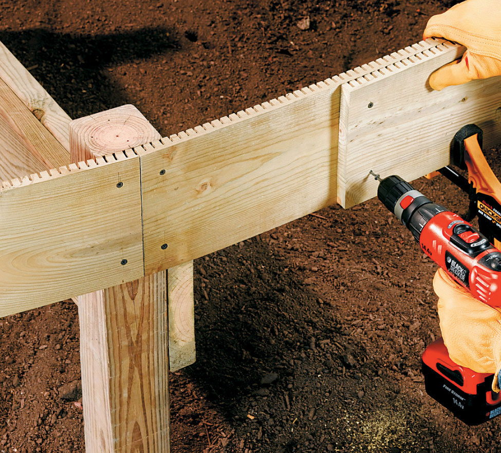
Install the next layer of kerfed 1 × 8s, driving pairs of screws every 12" and at each post location.
Place one end of the board in the intersection of an outer rim joist and inner joist at an outer corner post, with the kerfed face against the inner joist and its top edge flush with the top edges of the joists. Drill pilot holes and drive 3" deck screws through the end of the board into the joist and post.
Bend the other end of the board until it meets the face of the center post and attach it to the post with deck screws driven 1" from the centerpoint. Make sure the bottom edge of the curved joist is level with the top edge of the beam. Mark a straight cut line at the centerpoint of the post on the curved joist, using a speed square. Cut the board with a circular saw with its blade set 1/8" deeper than the thickness of the board.
Measure, cut, and kerf another 1 × 8 a few inches longer than needed to complete the span. Attach one end in the intersection of the other outer rim joist and corner post. Bend and clamp the board into position. Mark a cutting line for the board to meet the other curved joist at the center post. Cut it with the circular saw, drill pilot holes, and drive deck screws to attach it to the post before removing the clamps.
Measure, cut, and kerf another pair of 1 × 8s. Clamp them to the first layer, staggering the joints so they do not fall on the center post and aligning the ends so they protrude past the rim joists. Drill pilot holes and fasten with deck screws every 12" and at post locations, then trim the ends of the rim joists flush with the outer face of the curved rim joist, using a reciprocating saw.
Measure, cut, and install the remaining inner joists with 16" on-center spacing beginning at the wall side of the deck.
Select a 2 × 8 for the inner joist closest to the curved rim joist that is about 12" longer than necessary. Position it so its ends overlap the curved rim joist with its inner face aligned with the adjacent posts. Mark the profile of the inner face of the curved rim joist at each end of the inner joist. Cut the inner joist at these marks with a reciprocating saw, then install it with deck screws driven through it and into the curved rim joist.
Cut and install 2 × 8 blocking at the midpoints of the joist spans to provide support for the diagonal decking. Also install blocking between the curved rim joist and adjacent joists as necessary to help support the curved profile. Cut the tops of the posts flush with the top edges of the joists. Remove all braces and stakes supporting posts.
Cut the stair stringers to length from pressure-treated 2 × 12 lumber and use a framing square to mark the rise and run for each step. Cut the notches and the angles at the end of the stringers with a circular saw, then use a jigsaw to complete the corners.
Attach the side stair stringers to the joist ends. Attach the stringers for the curved stair to the blocking between the inner joists and the curved rim joist. Install additional blocking as necessary. Rip 1/4"-thick plywood sheets into 2 × 8-ft.-long pieces and trace the profile of the curved rim joist onto them. Cut out this profile, using a jigsaw, and use the plywood templates to mark the inside curve for the inner tread of the top step onto 10-ft.-long pieces of 2 × 12 lumber. Cut a 2"-wide piece of 2 × 6 lumber and use it as a spacer to mark the outside curve for the inner tread. Guide one end of the spacer along the inside curve line while holding a pencil point at the other end.
Cut the curved inner tread pieces using a jigsaw. Use the outside curved edge of the inner tread to mark the inside curve of the outer tread for the top step. Use the spacer to mark the outside edge, then cut the treads using a jigsaw.
Use the outside curved edge of the outer tread for the top step to mark the inside curved edge on the inner tread of the bottom step. Repeat the process used to mark and cut the top step treads to complete the bottom step treads.
Install the curved treads, drilling pilot holes and using deck screws. Make sure joints between tread pieces are supported by stringers.
Measure and cut the side treads from 2 × 6 lumber, and attach them to the side stair stringers.
Cut a 45° angle at the end of a deck board and position it with the long point 1/4" from the wall and centered on the midpoint blocking. The other end should overhang the rim joists at the opposite corner. Attach the board by driving two deck screws into each joist.
Cut and attach the rest of the deck boards on this side of the deck.
Cut and attach the deck boards for the other side of the deck, again letting ends overhang the rim joists. Trim the ends of the deck boards.
Mark and snap chalk lines across the overhanging board. Set the depth of the circular saw blade 1/8" deeper than the thickness of the decking and cut along the lines. Complete the cuts at the wall with a jigsaw, and a hammer and sharp chisel.
Use the plywood templates you cut for the stair installation to mark the curve on the ends of the decking boards overhanging the curved rim joist and trim, using a jigsaw.
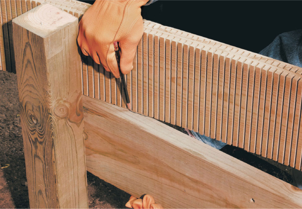
Mark the profile of the inner face of the curved rim joist on each end of the 2 × 8 for the inner joist at the curve. Cut the joist at the marks, then fasten to the posts with carriage bolts and to the curved rim joist with deck screws.
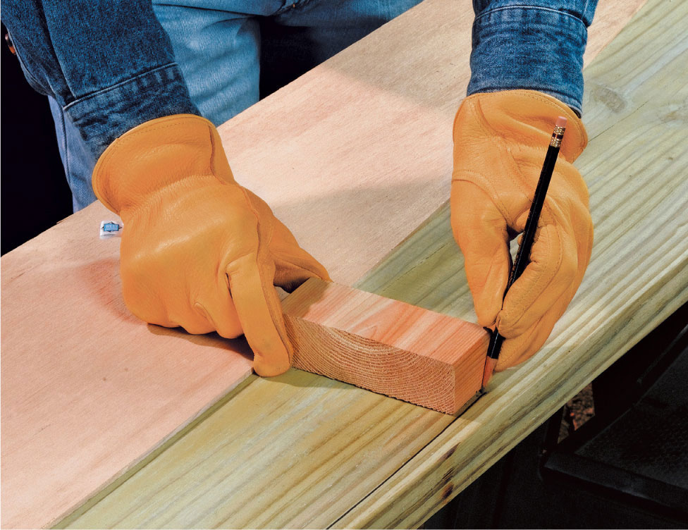
Cut a 2"-wide piece of 2 × 6 lumber and use it as a spacer to mark the outside curve for the inner tread.
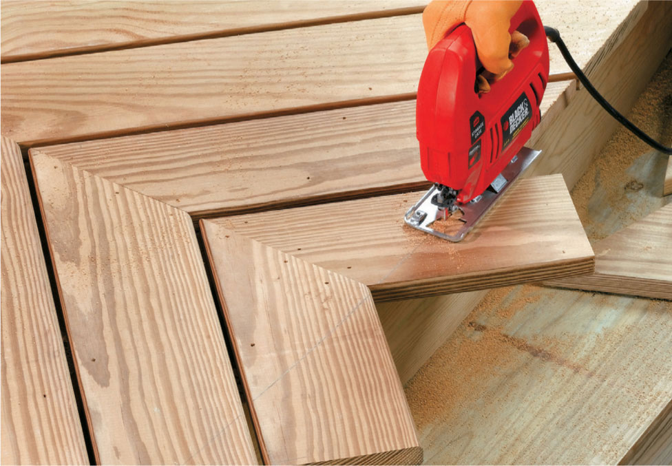
Use a jigsaw to trim the decking boards overhanging the curved rim joist.