When the 8086 CPU first appeared in the late 1970s, semiconductor technology was not to the point where Intel could put floating-point instructions directly on the 8086 CPU. Therefore, Intel devised a scheme whereby it could use a second chip to perform the floating-point calculations—the floating-point unit (or FPU).[102] By the release of the Intel Pentium chip, semiconductor technology had advanced to the point that the FPU was fully integrated onto the 80x86 CPU. Therefore, almost all modern 80x86 CPU devices fully support floating-point arithmetic directly on the CPU.
The 80x86 FPUs add 13 registers to the 80x86: eight floating-point data registers, a control register, a status register, a tag register, an instruction pointer, and a data pointer. The data registers are similar to the 80x86's general-purpose register set insofar as all floating-point calculations take place in these registers. The control register contains bits that let you decide how the FPU handles certain degenerate cases like rounding of inaccurate computations; it also contains bits that control precision and so on. The status register is similar to the 80x86's flags register; it contains the condition code bits and several other floating-point flags that describe the state of the FPU. The tag register contains several groups of bits that determine the state of the value in each of the eight floating-point data registers. The instruction and data pointer registers contain certain state information about the last floating-point instruction executed. We will not consider the last three registers here; see the Intel documentation for more details.
The FPUs provide eight 80-bit data registers organized as a stack. This is a significant departure from the organization of the general-purpose registers on the 80x86 CPU. HLA refers to these registers as ST0, ST1, . . . ST7.
The biggest difference between the FPU register set and the 80x86 register set is the stack organization. On the 80x86 CPU, the AX register is always the AX register, no matter what happens. On the FPU, however, the register set is an eight-element stack of 80-bit floating-point values (see Figure 6-1).

ST0 refers to the item on the top of the stack, ST1 refers to the next item on the stack, and so on. Many floating-point instructions push and pop items on the stack; therefore, ST1 will refer to the previous contents of ST0 after you push something onto the stack. It will take some thought and practice to get used to the fact that the register numbers change, but this is an easy problem to overcome.
When Intel designed the 80x87 (and, essentially, the IEEE floating-point standard), there were no standards in floating-point hardware. Different (mainframe and mini) computer manufacturers all had different and incompatible floating-point formats. Unfortunately, several applications had been written taking into account the idiosyncrasies of these different floating-point formats. Intel wanted to design an FPU that could work with the majority of the software out there (keep in mind that the IBM-PC was three to four years away when Intel began designing the 8087, so Intel couldn't rely on that "mountain" of software available for the PC to make its chip popular). Unfortunately, many of the features found in these older floating-point formats were mutually incompatible. For example, in some floating-point systems rounding would occur when there was insufficient precision; in others, truncation would occur. Some applications would work with one floating-point system but not with the other. Intel wanted as many applications as possible to work with as few changes as possible on its 80x87 FPUs, so it added a special register, the FPU control register, that lets the user choose one of several possible operating modes for the FPU.
The 80x87 control register contains 16 bits organized as shown in Figure 6-2.
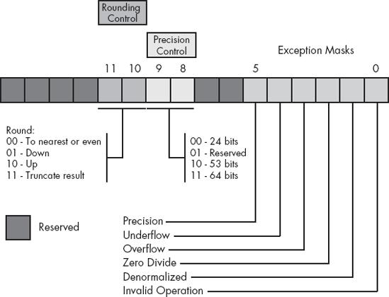
Bits 10 and 11 of the FPU control register provide rounding control according to the values appearing in Table 6-8.
The 00 setting is the default. The FPU rounds up values above one-half of the least significant bit. It rounds down values below one-half of the least significant bit. If the value below the least significant bit is exactly one-half of the least significant bit, then the FPU rounds the value toward the value whose least significant bit is 0. For long strings of computations, this provides a reasonable, automatic way to maintain maximum precision.
The round-up and round-down options are present for those computations where it is important to keep track of the accuracy during a computation. By setting the rounding control to round down and performing the operation, then repeating the operation with the rounding control set to round up, you can determine the minimum and maximum ranges between which the true result will fall.
The truncate option forces all computations to truncate any excess bits during the computation. You will rarely use this option if accuracy is important to you. However, if you are porting older software to the FPU, you might use this option to help when porting the software. One place where this option is extremely useful is when converting a floating-point value to an integer. Because most software expects floating-point-to-integer conversions to truncate the result, you will need to use the truncation/rounding mode to achieve this.
Bits 8 and 9 of the control register specify the precision during computation. This capability is provided to allow compatibility with older software as required by the IEEE 754 standard. The precision control bits use the values in Table 6-9.
Table 6-9. Mantissa Precision Control Bits
Bits 8 & 9 | Precision Control |
|---|---|
00 | 24 bits |
01 | Reserved |
10 | 53 bits |
11 | 64 bits |
Some CPUs may operate faster with floating-point values whose precision is 53 bits (i.e., 64-bit floating-point format) rather than 64 bits (i.e., 80-bit floating-point format). Please see the documentation for your specific processor for details. Generally, the CPU defaults these bits to %11 to select the 64-bit mantissa precision.
Bits 0..5 are the exception masks. These are similar to the interrupt enable bit in the 80x86's flags register. If these bits contain a 1, the corresponding condition is ignored by the FPU. However, if any bit contains 0, and the corresponding condition occurs, then the FPU immediately generates an interrupt so the program can handle the degenerate condition (typically, this would wind up raising an HLA exception; see the excepts.hhf header file for the exception values).
Bit 0 corresponds to an invalid operation error. This generally occurs as the result of a programming error. Situations that raise the invalid operation exception (ex.fInvalidOperation) include pushing more than eight items onto the stack or attempting to pop an item off an empty stack, taking the square root of a negative number, or loading a nonempty register.
Bit 1 masks the denormalized interrupt that occurs whenever you try to manipulate denormalized values. Denormalized exceptions occur when you load arbitrary extended-precision values into the FPU or work with very small numbers just beyond the range of the FPU's capabilities. Normally, you would probably not enable this exception. If you enable this exception and the FPU generates this interrupt, the HLA runtime system raises the ex.fDenormal exception.
Bit 2 masks the zero divide exception. If this bit contains 0, the FPU will generate an interrupt if you attempt to divide a nonzero value by 0. If you do not enable the zero division exception, the FPU will produce NaN (not a number) whenever you perform a zero division. It's probably a good idea to enable this exception by programming a 0 into this bit. Note that if your program generates this interrupt, the HLA runtime system will raise the ex.fDivByZero exception.
Bit 3 masks the overflow exception. The FPU will raise the overflow exception if a calculation overflows or if you attempt to store a value that is too large to fit into the destination operand (for example, storing a large extended-precision value into a single-precision variable). If you enable this exception and the FPU generates this interrupt, the HLA runtime system raises the ex.fOverflow exception.
Bit 4, if set, masks the underflow exception. Underflow occurs when the result is too small to fit in the destination operand. Like overflow, this exception can occur whenever you store a small extended-precision value into a smaller variable (single or double precision) or when the result of a computation is too small for extended precision. If you enable this exception and the FPU generates this interrupt, the HLA runtime system raises the ex.fUnderflow exception.
Bit 5 controls whether the precision exception can occur. A precision exception occurs whenever the FPU produces an imprecise result, generally the result of an internal rounding operation. Although many operations will produce an exact result, many more will not. For example, dividing 1 by 10 will produce an inexact result. Therefore, this bit is usually 1 because inexact results are very common. If you enable this exception and the FPU generates this interrupt, the HLA runtime system raises the ex.InexactResult exception.
Bits 6..7 and 12..15 in the control register are currently undefined and reserved for future use (bits 7 and 12 were valid on older FPUs but are no longer used).
The FPU provides two instructions, fldcw (load control word) and fstcw (store control word), that let you load and store the contents of the control register. The single operand to these instructions must be a 16-bit memory location. The fldcw instruction loads the control register from the specified memory location. fstcw stores the control register into the specified memory location. The syntax for these instructions is:
fldcw(mem16); fstcw(mem16);
Here's some example code that sets the rounding control to "truncate result" and sets the rounding precision to 24 bits:
static
     fcw16: word;
          .
          .
          .
          fstcw( fcw16 );
          mov( fcw16, ax );
          and( $f0ff, ax );      // Clears bits 8-11.
          or( $0c00, ax );       // Rounding control=%11, Precision = %00.
          mov( ax, fcw16 );
fldcw( fcw16 );The FPU status register provides the status of the FPU at the instant you read it. The fstsw instruction stores the16-bit floating-point status register into a word variable. The status register is a 16-bit register; its layout appears in Figure 6-3.
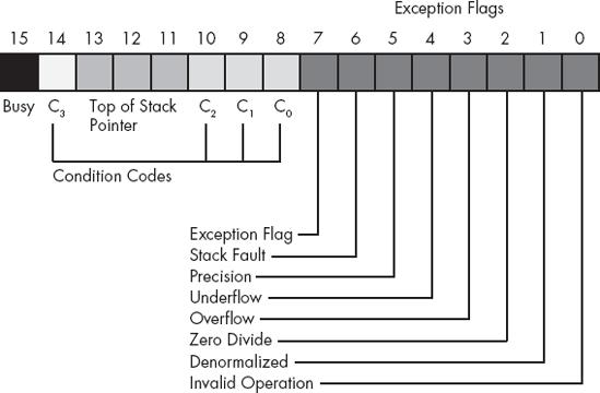
Bits 0 through 5 are the exception flags. These bits appear in the same order as the exception masks in the control register. If the corresponding condition exists, then the bit is set. These bits are independent of the exception masks in the control register. The FPU sets and clears these bits regardless of the corresponding mask setting.
Bit 6 indicates a stack fault. A stack fault occurs whenever there is a stack overflow or underflow. When this bit is set, the C1 condition code bit determines whether there was a stack overflow (C1 = 1) or stack underflow (C1 = 0) condition.
Bit 7 of the status register is set if any error condition bit is set. It is the logical or of bits 0 through 5. A program can test this bit to quickly determine if an error condition exists.
Bits 8, 9, 10, and 14 are the coprocessor condition code bits. Various instructions set the condition code bits, as shown in Table 6-10 and Table 6-11, respectively.
Table 6-10. FPU Condition Code Bits (X = "Don't care")
Condition Code Bits | Condition | ||||
|---|---|---|---|---|---|
C3 | C2 | C1 | C0 | ||
| 0 0 1 1 | 0 0 0 1 | X X X X | 0 1 0 1 | ST > source ST < source ST = source ST or source undefined |
| 0 0 1 1 | 0 0 0 1 | X X X X | 0 1 0 1 | ST is positive ST is negative ST is 0 (+ or −) ST is uncomparable |
0 0 0 0 1 1 1 1 0 0 0 0 1 | 0 0 1 1 0 0 1 1 0 0 1 1 X | 0 1 0 1 0 1 0 1 0 1 0 1 X |
0 0 0 0 0 0 0 1 1 1 1 1 | + Unnormalized − Unnormalized + Normalized − Normalized + 0 − 0 + Denormalized − Denormalized + NaN − NaN + Infinity − Infinity Empty register | |
| 0 0 1 1 | 0 0 0 1 | X X X X | 0 1 0 1 | ST > source ST < source ST = source Unordered |
Table 6-11. Condition Code Interpretations (X = "Don't care")
Instruction | Condition Code Bits | Condition | |||
|---|---|---|---|---|---|
C3 | C2 | C1 | C0 | ||
| 0 0 1 1 | 0 0 0 1 | X X X X | 0 1 0 1 | ST > source ST < source ST = source ST or source undefined |
| 0 0 1 1 | 0 0 0 1 | X X X X | 0 1 0 1 | ST is positive ST is negative ST is 0 (+ or −) ST is uncomparable |
| 0 0 0 0 1 1 1 1 0 0 0 0 1 | 0 0 1 1 0 0 1 1 0 0 1 1 X | 0 1 0 1 0 1 0 1 0 1 0 1 X | 1 0 0 0 0 0 0 0 1 1 1 1 1 | + Unnormalized − Unnormalized + Normalized − Normalized + 0 − 0 + Denormalized − Denormalized + NaN − NaN + Infinity − Infinity Empty register |
| 0 0 1 1 | 0 0 0 1 | X X X X | 0 1 0 1 | ST > source ST < source ST = source Unordered |
Bits 11–13 of the FPU status register provide the register number of the top of stack. During computations, the FPU adds (modulo-8) the logical register numbers supplied by the programmer to these three bits to determine the physical register number at runtime.
Bit 15 of the status register is the busy bit. It is set whenever the FPU is busy. This bit is a historical artifact from the days when the FPU was a separate chip; most programs will have little reason to access this bit.
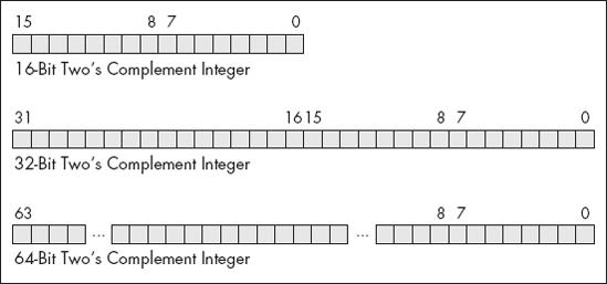
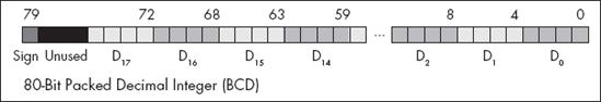
The FPU supports seven different data types: three integer types, a packed decimal type, and three floating-point types. The integer type supports 64-bit integers, although it is often faster to do the 64-bit arithmetic using the integer unit of the CPU (see Chapter 8). Certainly it is faster to do 16-bit and 32-bit integer arithmetic using the standard integer registers. The packed decimal type provides a 17-digit signed decimal (BCD) integer. The primary purpose of the BCD format is to convert between strings and floating-point values. The remaining three data types are the 32-bit, 64-bit, and 80-bit floating-point data types. The 80x87 data types appear in Figure 6-4, Figure 6-5, and Figure 6-6.

The FPU generally stores values in a normalized format. When a floating-point number is normalized, the H.O. bit of the mantissa is always 1. In the 32- and 64-bit floating-point formats, the FPU does not actually store this bit; the FPU always assumes that it is 1. Therefore, 32- and 64-bit floating-point numbers are always normalized. In the extended-precision 80-bit floating-point format, the FPU does not assume that the H.O. bit of the mantissa is 1; the H.O. bit of the mantissa appears as part of the string of bits.
Normalized values provide the greatest precision for a given number of bits. However, there are a large number of nonnormalized values that we cannot represent with the 80-bit format. These values are very close to 0 and represent the set of values whose mantissa H.O. bit is not 0. The FPUs support a special 80-bit form known as denormalized values. Denormalized values allow the FPU to encode very small values it cannot encode using normalized values, but denormalized values offer fewer bits of precision than normalized values. Therefore, using denormalized values in a computation may introduce some slight inaccuracy into a computation. Of course, this is always better than underflowing the denormalized value to 0 (which could make the computation even less accurate), but you must keep in mind that if you work with very small values you may lose some accuracy in your computations. Note that the FPU status register contains a bit you can use to detect when the FPU uses a denormalized value in a computation.
The FPU adds many instructions to the 80x86 instruction set. We can classify these instructions as data movement instructions, conversions, arithmetic instructions, comparisons, constant instructions, transcendental instructions, and miscellaneous instructions. The following sections describe each of the instructions in these categories.
The data movement instructions transfer data between the internal FPU registers and memory. The instructions in this category are fld, fst, fstp, and fxch. The fld instruction always pushes its operand onto the floating-point stack. The fstp instruction always pops the top of stack after storing the top of stack (TOS). The remaining instructions do not affect the number of items on the stack.
The fld instruction loads a 32-bit, 64-bit, or 80-bit floating-point value onto the stack. This instruction converts 32- and 64-bit operands to an 80-bit extended-precision value before pushing the value onto the floating-point stack.
The fld instruction first decrements the TOS pointer (bits 11–13 of the status register) and then stores the 80-bit value in the physical register specified by the new TOS pointer. If the source operand of the FLD instruction is a floating-point data register, sti, then the actual register the FPU uses for the load operation is the register number before decrementing the TOS pointer. Therefore, fld( st0 ); duplicates the value on the top of the stack.
The fld instruction sets the stack fault bit if stack overflow occurs. It sets the denormalized exception bit if you load an 80-bit denormalized value. It sets the invalid operation bit if you attempt to load an empty floating-point register onto the top of stack (or perform some other invalid operation).
Here are some examples:
fld( st1 );
          fld( real32_variable );
          fld( real64_variable );
          fld( real80_variable );
          fld( (type real64 [ebx]) );
          fld( real_constant );
Note that there is no way to directly load a 32-bit integer register onto the floating-point stack, even if that register contains a real32 value. To accomplish this, you must first store the integer register into a memory location; then you can push that memory location onto the FPU stack using the fld instruction. For example:
mov( eax,tempReal32); // Save real32 value in eax to memory. fld(tempReal32); // Push that real value onto the FPU stack.
Note that loading a constant via fld is actually an HLA extension. The FPU doesn't support this instruction type. HLA creates a real80 object in the constants segment and uses the address of this memory object as the true operand for fld.
The fst and fstp instructions copy the value on the top of the floating-point stack to another floating-point register or to a 32-, 64 -, or 80-bit memory variable. When copying data to a 32- or 64-bit memory variable, the FPU rounds the 80-bit extended-precision value on the top of stack to the smaller format as specified by the rounding control bits in the FPU control register.
The fstp instruction pops the value off the top of the stack when moving it to the destination location. It does this by incrementing the TOS pointer in the status register after accessing the data in ST0. If the destination operand is a floating-point register, the FPU stores the value at the specified register number before popping the data off the top of the stack.
Executing an fstp( st0 ); instruction effectively pops the data off the top of stack with no data transfer. Here are some examples:
fst(real32_variable); fst(real64_variable); fst(realArray[ ebx*8 ] ); fst( st2 ); fstp( st1 );
The last example above effectively pops ST1 while leaving ST0 on the top of stack.
The fst and fstp instructions will set the stack exception bit if a stack underflow occurs (attempting to store a value from an empty register stack). They will set the precision bit if there is a loss of precision during the store operation (this will occur, for example, when storing an 80-bit extended-precision value into a 32- or 64-bit memory variable and some bits are lost during conversion). They will set the underflow exception bit when storing an 80-bit value into a 32- or 64-bit memory variable, but the value is too small to fit into the destination operand. Likewise, these instructions will set the overflow exception bit if the value on the top of stack is too big to fit into a 32- or 64-bit memory variable. The fst and fstp instructions set the denormalized flag when you try to store a denormalized value into an 80-bit register or variable.[103] They set the invalid operation flag if an invalid operation (such as storing into an empty register) occurs. Finally, these instructions set the C1 condition bit if rounding occurs during the store operation (this occurs only when storing into a 32- or 64-bit memory variable and you have to round the mantissa to fit into the destination).
Note
Because of an idiosyncrasy in the FPU instruction set related to the encoding of the instructions, you cannot use the fst instruction to store data into a real80 memory variable. You may, however, store 80-bit data using the fstp instruction.
The fxch instruction exchanges the value on the top of stack with one of the other FPU registers. This instruction takes two forms: one with a single FPU register as an operand and the second without any operands. The first form exchanges the top of stack with the specified register. The second form of fxch swaps the top of stack with ST1.
Many FPU instructions, for example, fsqrt, operate only on the top of the register stack. If you want to perform such an operation on a value that is not on the top of stack, you can use the fxch instruction to swap that register with TOS, perform the desired operation, and then use the fxch to swap the TOS with the original register. The following example takes the square root of ST2:
fxch( st2 );
          fsqrt();
          fxch( st2 );
The fxch instruction sets the stack exception bit if the stack is empty. It sets the invalid operation bit if you specify an empty register as the operand. This instruction always clears the C1 condition code bit.
The FPU performs all arithmetic operations on 80-bit real quantities. In a sense, the fld and fst/fstp instructions are conversion instructions because they automatically convert between the internal 80-bit real format and the 32- and 64-bit memory formats. Nonetheless, we'll simply classify them as data movement operations, rather than conversions, because they are moving real values to and from memory. The FPU provides six other instructions that convert to or from integer or binary-coded decimal (BCD) format when moving data. These instructions are fild, fist, fistp, fisttp, fbld, and fbstp.
The fild (integer load) instruction converts a 16-, 32-, or 64-bit two's complement integer to the 80-bit extended-precision format and pushes the result onto the stack. This instruction always expects a single operand. This operand must be the address of a word, double-word, or quad-word integer variable. You cannot specify one of the 80x86's 16- or 32-bit general-purpose registers. If you want to push the value of an 80x86 general-purpose register onto the FPU stack, you must first store it into a memory variable and then use fild to push that memory variable.
The fild instruction sets the stack exception bit and C1 (accordingly) if stack overflow occurs while pushing the converted value. Look at these examples:
fild(word_variable); fild(dword_val[ ecx*4 ] ); fild(qword_variable); fild( (type int64 [ebx]) );
The fist, fistp, and fisttp instructions convert the 80-bit extended-precision variable on the top of stack to a 16-, 32-, or 64-bit integer and store the result away into the memory variable specified by the single operand. The fist and fistp instructions convert the value on TOS to an integer according to the rounding setting in the FPU control register (bits 10 and 11). The fisttp instruction always does the conversion using the truncation mode. As for the fild instruction, the fist, fistp, and fisttp instructions will not let you specify one of the 80x86's general-purpose 16- or 32-bit registers as the destination operand.
The fist instruction converts the value on the top of stack to an integer and then stores the result; it does not otherwise affect the floating-point register stack. The fistp and fisttp instructions pop the value off the floating-point register stack after storing the converted value.
These instructions set the stack exception bit if the floating-point register stack is empty (this will also clear C1). They set the precision (imprecise operation) and C1 bits if rounding occurs (that is, if there is any fractional component to the value in ST0). These instructions set the underflow exception bit if the result is too small (that is, less than 1 but greater than 0 or less than 0 but greater than −1). Here are some examples:
fist(word_var[ ebx*2 ] ); fist(qword_var); fisttp(dword_var); fistp(dword_var);
Don't forget that the fist and fistp instructions use the rounding control settings to determine how they will convert the floating-point data to an integer during the store operation. Be default, the rounding control is usually set to "round" mode; yet most programmers expect fist/fistp to truncate the decimal portion during conversion. If you want fist/fistp to truncate floating-point values when converting them to an integer, you will need to set the rounding control bits appropriately in the floating-point control register (or use the fisttp instruction to truncate the result regardless of the rounding control bits). Here's an example:
static
     fcw16:         word;
     fcw16_2:       word;
     IntResult:     int32;
          .
          .
          .
          fstcw( fcw16 );
          mov( fcw16, ax );
          or( $0c00, ax );        // Rounding control=%11 (truncate).
          mov( ax, fcw16_2 );     // Store into memory and reload the ctrl word.
          fldcw( fcw16_2 );

          fistp( IntResult );     // Truncate ST0 and store as int32 object.

fldcw( fcw16 ); // Restore original rounding control.The fbld and fbstp instructions load and store 80-bit BCD values. The fbld instruction converts a BCD value to its 80-bit extended-precision equivalent and pushes the result onto the stack. The fbstp instruction pops the extended-precision real value on TOS, converts it to an 80-bit BCD value (rounding according to the bits in the floating-point control register), and stores the converted result at the address specified by the destination memory operand. Note that there is no fbst instruction.
The fbld instruction sets the stack exception bit and C1 if stack overflow occurs. It sets the invalid operation bit if you attempt to load an invalid BCD value. The fbstp instruction sets the stack exception bit and clears C1 if stack underflow occurs (the stack is empty). It sets the underflow flag under the same conditions as fist and fistp. Look at these examples:
// Assuming fewer than 8 items on the stack, the following
// code sequence is equivalent to an fbst instruction:

          fld( st0 );
          fbstp( tbyte_var );

// The following example easily converts an 80-bit BCD value to
// a 64-bit integer:

          fbld( tbyte_var );
          fist( qword_var );
These two instructions are especially useful for converting between string and floating-point formats. See the floating-point-to-string and string-to-floating-point conversion routines in the HLA Standard Library for more details.
The arithmetic instructions make up a small but important subset of the FPU's instruction set. These instructions fall into two general categories: those that operate on real values and those that operate on a real and an integer value.
These two instructions take the following forms:
fadd()
          faddp()
          fadd( st0, sti );
          fadd( sti, st0 );
          faddp( st0, sti );
          fadd( mem_32_64 );
          fadd( real_constant );
The fadd instruction, with no operands, adds the value in ST0 to the value in ST1 and stores the result into ST1. The faddp instruction (with no operands) pops the two values on the top of stack, adds them, and pushes their sum back onto the stack.
The next two forms of the fadd instruction, those with two FPU register operands, behave like the 80x86's add instruction. They add the value in the source register operand to the value in the destination register operand. Note that one of the register operands must be ST0.
The faddp instruction with two operands adds ST0 (which must always be the source operand) to the destination operand and then pops ST0. The destination operand must be one of the other FPU registers.
The last form above, fadd with a memory operand, adds a 32- or 64-bit floating-point variable to the value in ST0. This instruction will convert the 32- or 64-bit operands to an 80-bit extended-precision value before performing the addition. Note that this instruction does not allow an 80-bit memory operand.
These instructions can raise the stack, precision, underflow, overflow, denormalized, and illegal operation exceptions, as appropriate. If a stack fault exception occurs, C1 denotes stack overflow or underflow.
Like fld( real_constant), the fadd( real_constant ) instruction is an HLA extension. Note that it creates a 64-bit variable holding the constant value and emits the fadd( mem64 ) instruction, specifying the read-only object it creates in the constants segment.
These four instructions take the following forms:
fsub()
          fsubp()
          fsubr()
          fsubrp()

          fsub( st0, sti )
          fsub( sti, st0 );
          fsubp( st0, sti );
          fsub( mem_32_64 );
          fsub( real_constant );

          fsubr( st0, sti )
          fsubr( sti, st0 );
          fsubrp( st0, sti );
          fsubr( mem_32_64 );
          fsubr( real_constant );
With no operands, the fsub instruction subtracts ST0 from ST1 and leaves the result in ST1. With no operands the fsubp instruction pops ST0 and ST1 from the register stack, computes st1 - st0 and then pushes the difference back onto the stack. The fsubr and fsubrp instructions (reverse subtraction) operate in an almost identical fashion except they compute st0 - st1.
With two register operands (source, destination) the fsub instruction computes destination := destination - source. One of the two registers must be ST0. With two registers as operands, the fsubp also computes destination := destination - source, and then it pops ST0 off the stack after computing the difference. For the fsubp instruction, the source operand must be ST0.
With two register operands, the fsubr and fsubrp instructions work in a similar fashion to fsub and fsubp, except they compute destination := source - destination.
The fsub( mem ) and fsubr( mem ) instructions accept a 32- or 64-bit memory operand. They convert the memory operand to an 80-bit extended-precision value and subtract this from ST0 (fsub) or subtract ST0 from this value (fsubr) and store the result back into ST0.
These instructions can raise the stack, precision, underflow, overflow, denormalized, and illegal operation exceptions, as appropriate. If a stack fault exception occurs, C1 denotes stack overflow or underflow.
Note
The instructions that have real constants as operands aren't true FPU instructions. These are extensions provided by HLA. HLA generates a constant segment memory object initialized with the constant's value.
The fmul and fmulp instructions multiply two floating-point values. These instructions allow the following forms:
fmul()
          fmulp()

          fmul( sti, st0 );
          fmul( st0, sti );
          fmul( mem_32_64 );
          fmul( real_constant );

          fmulp( st0, sti );
With no operands, fmul will compute st0 * st1 and store the product into ST1. The fmulp instruction, with no operands, will pop ST0 and ST1, multiply these values, and push their product back onto the stack. The fmul instructions with two register operands compute destination := destination * source. One of the registers (source or destination) must be ST0.
The fmulp( st0, sti ) instruction computes sti := sti * st0 and then pops ST0. This instruction uses the value for STi before popping ST0. The fmul( mem ) instruction requires a 32- or 64-bit memory operand. It converts the specified memory variable to an 80-bit extended-precision value and then multiplies ST0 by this value.
These instructions can raise the stack, precision, underflow, overflow, denormalized, and illegal operation exceptions, as appropriate. If rounding occurs during the computation, these instructions set the C1 condition code bit. If a stack fault exception occurs, C1 denotes stack overflow or underflow.
Note
The instruction that has a real constant as its operand isn't a true FPU instruction. It is an extension provided by HLA (see the note at the end of 6.5.6.2 The fsub, fsubp, fsubr, and fsurpb Instructions for details).
These four instructions allow the following forms:
fdiv()
          fdivp()
          fdivr()
          fdivrp()

          fdiv( sti, st0 );
          fdiv( st0, sti );
          fdivp( st0, sti );

          fdivr( sti, st0 );
          fdivr( st0, sti );
          fdivrp( st0, sti );

          fdiv( mem_32_64 );
          fdivr( mem_32_64 );
          fdiv( real_constant );
          fdivr( real_constant );
With no operands, the fdivp instruction pops ST0 and ST1, computes st1/st0, and pushes the result back onto the stack. The fdiv instruction with no operands computes st1 := st1/st0. The fdivr and fdivrp instructions work in a similar fashion to fdiv and fdivp except that they compute st0/st1 rather than st1/st0.
With two register operands, these instructions compute the following quotients:
fdiv( sti, st0 ); // st0 := st0/stifdiv( st0, sti); // sti:= sti/st0 fdivp( st0, sti); // sti:= sti/st0 then pop st0 fdivr( st0, sti); // st0 := st0/stifdivrp( st0, sti); // sti:= st0/stithen pop st0
The fdivp and fdivrp instructions also pop ST0 after performing the division operation. The value for i in these two instructions is computed before popping ST0.
These instructions can raise the stack, precision, underflow, overflow, denormalized, zero divide, and illegal operation exceptions, as appropriate. If rounding occurs during the computation, these instructions set the C1 condition code bit. If a stack fault exception occurs, C1 denotes stack overflow or underflow.
Note that the instructions that have real constants as operands aren't true FPU instructions. These are extensions provided by HLA.
The fsqrt routine does not allow any operands. It computes the square root of the value on top of stack (TOS) and replaces ST0 with this result. The value on TOS must be 0 or positive; otherwise fsqrt will generate an invalid operation exception.
This instruction can raise the stack, precision, denormalized, and invalid operation exceptions, as appropriate. If rounding occurs during the computation, fsqrt sets the C1 condition code bit. If a stack fault exception occurs, C1 denotes stack overflow or underflow.
Here's an example:
// Compute z := sqrt(x**2 + y**2);

          fld( x );                  // Load x.
          fld( st0 );                // Duplicate x on TOS.
          fmulp();                   // Compute x**2.

          fld( y );                  // Load y.
          fld( st0 );                // Duplicate y.
          fmul();                    // Compute y**2.

          faddp();                   // Compute x**2 + y**2.
          fsqrt();                   // Compute sqrt( x**2 + y**2 ).
fstp( z ); // Store result away into z.The fprem and fprem1 instructions compute a partial remainder. Intel designed the fprem instruction before the IEEE finalized its floating-point standard. In the final draft of the IEEE floating-point standard, the definition of fprem was a little different than Intel's original design. Unfortunately, Intel needed to maintain compatibility with the existing software that used the fprem instruction, so it designed a new version to handle the IEEE partial remainder operation, fprem1. You should always use fprem1 in new software; therefore we will discuss only fprem1 here, although you use fprem in an identical fashion.
fprem1 computes the partial remainder of st0/st1. If the difference between the exponents of ST0 and ST1 is less than 64, fprem1 can compute the exact remainder in one operation. Otherwise you will have to execute the fprem1 two or more times to get the correct remainder value. The C2 condition code bit determines when the computation is complete. Note that fprem1 does not pop the two operands off the stack; it leaves the partial remainder in ST0 and the original divisor in ST1 in case you need to compute another partial product to complete the result.
The fprem1 instruction sets the stack exception flag if there aren't two values on the top of stack. It sets the underflow and denormal exception bits if the result is too small. It sets the invalid operation bit if the values on TOS are inappropriate for this operation. It sets the C2 condition code bit if the partial remainder operation is not complete. Finally, it loads C3, C1, and C0 with bits 0, 1, and 2 of the quotient, respectively.
An example follows:
// Compute z := x mod y

          fld( y );
          fld( x );
          repeat

               fprem1();
               fstsw( ax );   // Get condition code bits into ax.
               and( 1, ah );  // See if C2 is set.

          until( @z );        // Repeat until C2 is clear.
          fstp( z );          // Store away the remainder.
fstp( st0 ); // Pop old y value.The frndint instruction rounds the value on the top of stack (TOS) to the nearest integer using the rounding algorithm specified in the control register.
This instruction sets the stack exception flag if there is no value on the TOS (it will also clear C1 in this case). It sets the precision and denormal exception bits if there was a loss of precision. It sets the invalid operation flag if the value on the TOS is not a valid number. Note that the result on TOS is still a floating-point value; it simply does not have a fractional component.
fabs computes the absolute value of ST0 by clearing the mantissa sign bit of ST0. It sets the stack exception bit and invalid operation bits if the stack is empty.
Here's an example:
// Compute x := sqrt(abs(x));

          fld( x );
          fabs();
          fsqrt();
fstp( x );fchs changes the sign of ST0's value by inverting the mantissa sign bit (that is, this is the floating-point negation instruction). It sets the stack exception bit and invalid operation bits if the stack is empty.
Look at this example:
// Compute x := -x if x is positive, x := x if x is negative.
// That is, force x to be a negative value.

          fld( x );
          fabs();
          fchs();
fstp( x );The FPU provides several instructions for comparing real values. The fcom, fcomp, and fcompp instructions compare the two values on the top of stack and set the condition codes appropriately. The ftst instruction compares the value on the top of stack with 0.
Generally, most programs test the condition code bits immediately after a comparison. Unfortunately, there are no FPU instructions that test the FPU condition codes. Instead, you use the fstsw instruction to copy the floating-point status register into the AX register; then you can use the sahf instruction to copy the AH register into the 80x86's condition code bits. After doing this, you can test the standard 80x86 flags to check for some condition. This technique copies C0 into the carry flag, C2 into the parity flag, and C3 into the zero flag. The sahf instruction does not copy C1 into any of the 80x86's flag bits.
Because the sahf instruction does not copy any FPU status bits into the sign or overflow flags, you cannot use signed comparison instructions. Instead, use unsigned operations (e.g., seta, setb) when testing the results of a floating-point comparison. Yes, these instructions normally test unsigned values, and floating-point numbers are signed values. However, use the unsigned operations anyway; the fstsw and sahf instructions set the 80x86 flags register as though you had compared unsigned values with the cmp instruction.
The Pentium II and (upward) compatible processors provide an extra set of floating-point comparison instructions that directly affect the 80x86 condition code flags. These instructions circumvent having to use fstsw and sahf to copy the FPU status into the 80x86 condition codes. These instructions include fcomi and fcomip. You use them just like the fcom and fcomp instructions, except, of course, you do not have to manually copy the status bits to the FLAGS register.
The fcom, fcomp, and fcompp instructions compare ST0 to the specified operand and set the corresponding FPU condition code bits based on the result of the comparison. The legal forms for these instructions are:
fcom()
          fcomp()
          fcompp()

          fcom( sti )
          fcomp( sti )

          fcom( mem_32_64 )
          fcomp( mem_32_64 )
          fcom( real_constant )
          fcomp( real_constant )
With no operands, fcom, fcomp, and fcompp compare ST0 against ST1 and set the FPU flags accordingly. In addition, fcomp pops ST0 off the stack and fcompp pops both ST0 and ST1 off the stack.
With a single-register operand, fcom and fcomp compare ST0 against the specified register. fcomp also pops ST0 after the comparison.
With a 32- or 64-bit memory operand, the fcom and fcomp instructions convert the memory variable to an 80-bit extended-precision value and then compare ST0 against this value, setting the condition code bits accordingly. fcomp also pops ST0 after the comparison.
These instructions set C2 (which winds up in the parity flag) if the two operands are not comparable (e.g., NaN). If it is possible for an illegal floating-point value to wind up in a comparison, you should check the parity flag for an error before checking the desired condition (e.g., using HLA's @p and @np conditions, or by using the setp/setnp instructions).
These instructions set the stack fault bit if there aren't two items on the top of the register stack. They set the denormalized exception bit if either or both operands are denormalized. They set the invalid operation flag if either or both operands are quiet NaNs. These instructions always clear the C1 condition code.
Note that the instructions that have real constants as operands aren't true FPU instructions. These are extensions provided by HLA. When HLA encounters such an instruction, it creates a real64 read-only variable in the constants segment and initializes this variable with the specified constant. Then HLA translates the instruction to one that specifies a real64 memory operand.
Note
Because of the precision differences (64 bits versus 80 bits), if you use a constant operand in a floating-point instruction you may not get results that are as precise as you would expect.
Let's look at an example of a floating-point comparison:
fcompp();
          fstsw( ax );
          sahf();
          setb( al );   // al = true if st1 < st0.
               .
               .
               .
Note that you cannot compare floating-point values in an HLA runtime boolean expression (e.g., within an if statement). You may, however, test the conditions in such statements after a floating-point comparison like the sequence above. For example:
fcompp();
          fstsw( ax );
          sahf();
          if( @b ) then

               << Code that executes if st1 < st0 >>

endif;The fcomi and fcomip instructions compare ST0 to the specified operand and set the corresponding EFLAG condition code bits based on the result of the comparison. You use these instructions in a similar manner to fcom and fcomp except you can test the CPU's flag bits directly after the execution of these instructions without first moving the FPU status bits into the EFLAGS register. The legal forms for these instructions are as follows:
fcomi()
          fcomip()
          fcomi( sti )
          fcomip( sti )

          fcomi( mem_32_64 )
          fcomip( mem_32_64 )
          fcomi( real_constant )
fcomip( real_constant )The ftst instruction compares the value in ST0 against 0.0. It behaves just like the fcom instruction would if ST1 contained 0.0. Note that this instruction does not differentiate −0.0 from +0.0. If the value in ST0 is either of these values, ftst will set C3 to denote equality. This instruction does not pop ST0 off the stack.
Here's an example:
ftst();
          fstsw( ax );
          sahf();
sete( al ); // Set al to 1 if TOS = 0.0The FPU provides several instructions that let you load commonly used constants onto the FPU's register stack. These instructions set the stack fault, invalid operation, and C1 flags if a stack overflow occurs; they do not otherwise affect the FPU flags. The specific instructions in this category include the following:
fldz()               // Pushes +0.0.
          fld1()               // Pushes +1.0.
          fldpi()              // Pushes pi.
          fldl2t()             // Pushes log2(10).
          fldl2e()             // Pushes log2(e).
          fldlg2()             // Pushes log10(2).
fldln2() // Pushes ln(2).The FPU provides eight transcendental (logarithmic and trigonometric) instructions to compute sine, cosine, partial tangent, partial arctangent, 2x - 1, y * log2(x), and y * log2(x + 1). Using various algebraic identities, it is easy to compute most of the other common transcendental functions using these instructions.
f2xm1 computes 2ST0 - 1. The value in ST0 must be in the range −1.0..ST0..+1.0. If ST0 is out of range, f2xm1 generates an undefined result but raises no exceptions. The computed value replaces the value in ST0.
Here's an example computing 10x using the identity 10x = 2x *log2(10). This is only useful for a small range of x that doesn't put ST0 outside of the previously mentioned valid range.
fld( x );
          fldl2t();
          fmul();
          f2xm1();
          fld1();
          fadd();
Note that f2xm1 computes 2x - 1, which is why the code above adds 1.0 to the result at the end of the computation.
These instructions pop the value off the top of the register stack and compute the sine, cosine, or both and push the result(s) back onto the stack. The fsincos instruction pushes the sine followed by the cosine of the original operand; hence it leaves cos(ST0) in ST0 and sin(ST0) in ST1.
These instructions assume ST0 specifies an angle in radians and this angle must be in the range −263 < ST0 < +263. If the original operand is out of range, these instructions set the C2 flag and leave ST0 unchanged. You can use the fprem1 instruction, with a divisor of 2π, to reduce the operand to a reasonable range.
These instructions set the stack fault/C1, precision, underflow, denormalized, and invalid operation flags according to the result of the computation.
fptan computes the tangent of ST0 and pushes this value, and then it pushes 1.0 onto the stack. Like the fsin and fcos instructions, the value of ST0 must be in radians and in the range −263 < ST0 < +263. If the value is outside this range, fptan sets C2 to indicate that the conversion did not take place. As with the fsin, fcos, and fsincos instructions, you can use the fprem1 instruction to reduce this operand to a reasonable range using a divisor of 2π.
If the argument is invalid (i.e., zero or π radians, which causes a division by 0), the result is undefined and this instruction raises no exceptions. fptan will set the stack fault, precision, underflow, denormal, invalid operation, C2, and C1 bits as required by the operation.
This instruction expects two values on the top of stack. It pops them and computes ST0 = tan−1(ST1/ST0).
The resulting value is the arctangent of the ratio on the stack expressed in radians. If you have a value you wish to compute the tangent of, use fld1 to create the appropriate ratio and then execute the fpatan instruction.
This instruction affects the stack fault/C1, precision, underflow, denormal, and invalid operation bits if a problem occurs during the computation. It sets the C1 condition code bit if it has to round the result.
This instruction expects two operands on the FPU stack: y is found in ST1 and x is found in ST0. This function computes ST0 = ST1 * log2(ST0).
This instruction has no operands (to the instruction itself ). The instruction uses the following syntax:
fyl2x();
Note that this instruction computes the base-2 logarithm. Of course, it is a trivial matter to compute the log of any other base by multiplying by the appropriate constant.
The FPU includes several additional instructions that control the FPU, synchronize operations, and let you test or set various status bits. These instructions include finit/fninit, fldcw, fstcw, fclex/fnclex, and fstsw.
The finit instruction initializes the FPU for proper operation. Your applications should execute this instruction before executing any other FPU instructions. This instruction initializes the control register to $37F, the status register to 0, and the tag word to $FFFF. The other registers are unaffected.
Here are some examples:
finit();
         fninit();
The difference between finit and fninit is that finit first checks for any pending floating-point exceptions before initializing the FPU; fninit does not.
The fldcw and fstcw instructions require a single 16-bit memory operand:
fldcw(mem16); fstcw(mem16);
These two instructions load the control register from a memory location (fldcw) or store the control word to a 16-bit memory location (fstcw).
When using the fldcw instruction to turn on one of the exceptions, if the corresponding exception flag is set when you enable that exception, the FPU will generate an immediate interrupt before the CPU executes the next instruction. Therefore, you should use the fclex instruction to clear any pending interrupts before changing the FPU exception enable bits.
The fclex and fnclex instructions clear all exception bits, the stack fault bit, and the busy flag in the FPU status register.
Here are some examples:
fclex();
     fnclex();
The difference between these instructions is the same as between finit and fninit.
These instructions store the FPU status register into a 16-bit memory location or the AX register.
fstsw( ax );
          fnstsw( ax );
          fstsw( mem16 );
          fnstsw( mem16 );
These instructions are unusual in the sense that they can copy an FPU value into one of the 80x86 general-purpose registers (specifically, AX). Of course, the whole purpose behind allowing the transfer of the status register into AX is to allow the CPU to easily test the condition code register with the sahf instruction. The difference between fstsw and fnstsw is the same as for fclex and fnclex.
The FPU provides special instructions that combine integer-to-extended-precision conversion with various arithmetic and comparison operations. These instructions are the following:
fiadd(int_16_32); fisub(int_16_32); fisubr(int_16_32); fimul(int_16_32); fidiv(int_16_32); fidivr(int_16_32); ficom(int_16_32); ficomp(int_16_32);
These instructions convert their 16- or 32-bit integer operands to an 80-bit extended-precision floating-point value and then use this value as the source operand for the specified operation. These instructions use ST0 as the destination operand.