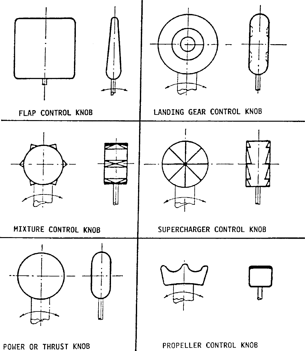
§25.781 Cockpit control knob shape.
Cockpit control knobs must conform to the general shapes (but not necessarily the exact sizes or specific proportions) in the following figure:
[Doc. No. 5066, 29 FR 18291, Dec. 24, 1964, as amended by Amdt. 25-72, 55 FR 29779, July 20, 1990]
§25.783 Fuselage doors.
(a) General. This section applies to fuselage doors, which includes all doors, hatches, openable windows, access panels, covers, etc., on the exterior of the fuselage that do not require the use of tools to open or close. This also applies to each door or hatch through a pressure bulkhead, including any bulkhead that is specifically designed to function as a secondary bulkhead under the prescribed failure conditions of part 25. These doors must meet the requirements of this section, taking into account both pressurized and unpressurized flight, and must be designed as follows:
(1) Each door must have means to safeguard against opening in flight as a result of mechanical failure, or failure of any single structural element.
(2) Each door that could be a hazard if it unlatches must be designed so that unlatching during pressurized and unpressurized flight from the fully closed, latched, and locked condition is extremely improbable. This must be shown by safety analysis.
(3) Each element of each door operating system must be designed or, where impracticable, distinctively and permanently marked, to minimize the probability of incorrect assembly and adjustment that could result in a malfunction.
(4) All sources of power that could initiate unlocking or unlatching of any door must be automatically isolated from the latching and locking systems prior to flight and it must not be possible to restore power to the door during flight.
(5) Each removable bolt, screw, nut, pin, or other removable fastener must meet the locking requirements of §25.607.
(6) Certain doors, as specified by §25.807(h), must also meet the applicable requirements of §§25.809 through 25.812 for emergency exits.
(b) Opening by persons. There must be a means to safeguard each door against opening during flight due to inadvertent action by persons. In addition, design precautions must be taken to minimize the possibility for a person to open a door intentionally during flight. If these precautions include the use of auxiliary devices, those devices and their controlling systems must be designed so that—
(1) No single failure will prevent more than one exit from being opened; and
(2) Failures that would prevent opening of the exit after landing are improbable.
(c) Pressurization prevention means. There must be a provision to prevent pressurization of the airplane to an unsafe level if any door subject to pressurization is not fully closed, latched, and locked.
(1) The provision must be designed to function after any single failure, or after any combination of failures not shown to be extremely improbable.
(2) Doors that meet the conditions described in paragraph (h) of this section are not required to have a dedicated pressurization prevention means if, from every possible position of the door, it will remain open to the extent that it prevents pressurization or safely close and latch as pressurization takes place. This must also be shown with any single failure and malfunction, except that—
(i) With failures or malfunctions in the latching mechanism, it need not latch after closing; and
(ii) With jamming as a result of mechanical failure or blocking debris, the door need not close and latch if it can be shown that the pressurization loads on the jammed door or mechanism would not result in an unsafe condition.
(d) Latching and locking. The latching and locking mechanisms must be designed as follows:
(1) There must be a provision to latch each door.
(2) The latches and their operating mechanism must be designed so that, under all airplane flight and ground loading conditions, with the door latched, there is no force or torque tending to unlatch the latches. In addition, the latching system must include a means to secure the latches in the latched position. This means must be independent of the locking system.
(3) Each door subject to pressurization, and for which the initial opening movement is not inward, must—
(i) Have an individual lock for each latch;
(ii) Have the lock located as close as practicable to the latch; and
(iii) Be designed so that, during pressurized flight, no single failure in the locking system would prevent the locks from restraining the latches necessary to secure the door.
(4) Each door for which the initial opening movement is inward, and unlatching of the door could result in a hazard, must have a locking means to prevent the latches from becoming disengaged. The locking means must ensure sufficient latching to prevent opening of the door even with a single failure of the latching mechanism.
(5) It must not be possible to position the lock in the locked position if the latch and the latching mechanism are not in the latched position.
(6) It must not be possible to unlatch the latches with the locks in the locked position. Locks must be designed to withstand the limit loads resulting from—
(i) The maximum operator effort when the latches are operated manually;
(ii) The powered latch actuators, if installed; and
(iii) The relative motion between the latch and the structural counterpart.
(7) Each door for which unlatching would not result in a hazard is not required to have a locking mechanism meeting the requirements of paragraphs (d)(3) through (d)(6) of this section.
(e) Warning, caution, and advisory indications. Doors must be provided with the following indications:
(1) There must be a positive means to indicate at each door operator’s station that all required operations to close, latch, and lock the door(s) have been completed.
(2) There must be a positive means clearly visible from each operator station for any door that could be a hazard if unlatched to indicate if the door is not fully closed, latched, and locked.
(3) There must be a visual means on the flight deck to signal the pilots if any door is not fully closed, latched, and locked. The means must be designed such that any failure or combination of failures that would result in an erroneous closed, latched, and locked indication is improbable for—
(i) Each door that is subject to pressurization and for which the initial opening movement is not inward; or
(ii) Each door that could be a hazard if unlatched.
(4) There must be an aural warning to the pilots prior to or during the initial portion of takeoff roll if any door is not fully closed, latched, and locked, and its opening would prevent a safe takeoff and return to landing.
(f) Visual inspection provision. Each door for which unlatching of the door could be a hazard must have a provision for direct visual inspection to determine, without ambiguity, if the door is fully closed, latched, and locked. The provision must be permanent and discernible under operational lighting conditions, or by means of a flashlight or equivalent light source.
(g) Certain maintenance doors, removable emergency exits, and access panels. Some doors not normally opened except for maintenance purposes or emergency evacuation and some access panels need not comply with certain paragraphs of this section as follows:
(1) Access panels that are not subject to cabin pressurization and would not be a hazard if open during flight need not comply with paragraphs (a) through (f) of this section, but must have a means to prevent inadvertent opening during flight.
(2) Inward-opening removable emergency exits that are not normally removed, except for maintenance purposes or emergency evacuation, and flight deck-openable windows need not comply with paragraphs (c) and (f) of this section.
(3) Maintenance doors that meet the conditions of paragraph (h) of this section, and for which a placard is provided limiting use to maintenance access, need not comply with paragraphs (c) and (f) of this section.
(h) Doors that are not a hazard. For the purposes of this section, a door is considered not to be a hazard in the unlatched condition during flight, provided it can be shown to meet all of the following conditions:
(1) Doors in pressurized compartments would remain in the fully closed position if not restrained by the latches when subject to a pressure greater than 1⁄2 psi. Opening by persons, either inadvertently or intentionally, need not be considered in making this determination.
(2) The door would remain inside the airplane or remain attached to the airplane if it opens either in pressurized or unpressurized portions of the flight. This determination must include the consideration of inadvertent and intentional opening by persons during either pressurized or unpressurized portions of the flight.
(3) The disengagement of the latches during flight would not allow depressurization of the cabin to an unsafe level. This safety assessment must include the physiological effects on the occupants.
(4) The open door during flight would not create aerodynamic interference that could preclude safe flight and landing.
(5) The airplane would meet the structural design requirements with the door open. This assessment must include the aeroelastic stability requirements of §25.629, as well as the strength requirements of subpart C of this part.
(6) The unlatching or opening of the door must not preclude safe flight and landing as a result of interaction with other systems or structures.
[Doc. No. 2003-14193, 69 FR 24501, May 3, 2004]
§25.785 Seats, berths, safety belts, and harnesses.
(a) A seat (or berth for a nonambulant person) must be provided for each occupant who has reached his or her second birthday.
(b) Each seat, berth, safety belt, harness, and adjacent part of the airplane at each station designated as occupiable during takeoff and landing must be designed so that a person making proper use of these facilities will not suffer serious injury in an emergency landing as a result of the inertia forces specified in §§25.561 and 25.562.
(c) Each seat or berth must be approved.
(d) Each occupant of a seat that makes more than an 18-degree angle with the vertical plane containing the airplane centerline must be protected from head injury by a safety belt and an energy absorbing rest that will support the arms, shoulders, head, and spine, or by a safety belt and shoulder harness that will prevent the head from contacting any injurious object. Each occupant of any other seat must be protected from head injury by a safety belt and, as appropriate to the type, location, and angle of facing of each seat, by one or more of the following:
(1) A shoulder harness that will prevent the head from contacting any injurious object.
(2) The elimination of any injurious object within striking radius of the head.
(3) An energy absorbing rest that will support the arms, shoulders, head, and spine.
(e) Each berth must be designed so that the forward part has a padded end board, canvas diaphragm, or equivalent means, that can withstand the static load reaction of the occupant when subjected to the forward inertia force specified in §25.561. Berths must be free from corners and protuberances likely to cause injury to a person occupying the berth during emergency conditions.
(f) Each seat or berth, and its supporting structure, and each safety belt or harness and its anchorage must be designed for an occupant weight of 170 pounds, considering the maximum load factors, inertia forces, and reactions among the occupant, seat, safety belt, and harness for each relevant flight and ground load condition (including the emergency landing conditions prescribed in §25.561). In addition—
(1) The structural analysis and testing of the seats, berths, and their supporting structures may be determined by assuming that the critical load in the forward, sideward, downward, upward, and rearward directions (as determined from the prescribed flight, ground, and emergency landing conditions) acts separately or using selected combinations of loads if the required strength in each specified direction is substantiated. The forward load factor need not be applied to safety belts for berths.
(2) Each pilot seat must be designed for the reactions resulting from the application of the pilot forces prescribed in §25.395.
(3) The inertia forces specified in §25.561 must be multiplied by a factor of 1.33 (instead of the fitting factor prescribed in §25.625) in determining the strength of the attachment of each seat to the structure and each belt or harness to the seat or structure.
(g) Each seat at a flight deck station must have a restraint system consisting of a combined safety belt and shoulder harness with a single-point release that permits the flight deck occupant, when seated with the restraint system fastened, to perform all of the occupant’s necessary flight deck functions. There must be a means to secure each combined restraint system when not in use to prevent interference with the operation of the airplane and with rapid egress in an emergency.
(h) Each seat located in the passenger compartment and designated for use during takeoff and landing by a flight attendant required by the operating rules of this chapter must be:
(1) Near a required floor level emergency exit, except that another location is acceptable if the emergency egress of passengers would be enhanced with that location. A flight attendant seat must be located adjacent to each Type A or B emergency exit. Other flight attendant seats must be evenly distributed among the required floor- level emergency exits to the extent feasible.
(2) To the extent possible, without compromising proximity to a required floor level emergency exit, located to provide a direct view of the cabin area for which the flight attendant is responsible.
(3) Positioned so that the seat will not interfere with the use of a passageway or exit when the seat is not in use.
(4) Located to minimize the probability that occupants would suffer injury by being struck by items dislodged from service areas, stowage compartments, or service equipment.
(5) Either forward or rearward facing with an energy absorbing rest that is designed to support the arms, shoulders, head, and spine.
(6) Equipped with a restraint system consisting of a combined safety belt and shoulder harness unit with a single point release. There must be means to secure each restraint system when not in use to prevent interference with rapid egress in an emergency.
(i) Each safety belt must be equipped with a metal to metal latching device.
(j) If the seat backs do not provide a firm handhold, there must be a handgrip or rail along each aisle to enable persons to steady themselves while using the aisles in moderately rough air.
(k) Each projecting object that would injure persons seated or moving about the airplane in normal flight must be padded.
(l) Each forward observer’s seat required by the operating rules must be shown to be suitable for use in conducting the necessary enroute inspection.
[Amdt. 25-72, 55 FR 29780, July 20, 1990, as amended by Amdt. 25-88, 61 FR 57956, Nov. 8, 1996]
§25.787 Stowage compartments.
(a) Each compartment for the stowage of cargo, baggage, carry-on articles, and equipment (such as life rafts), and any other stowage compartment, must be designed for its placarded maximum weight of contents and for the critical load distribution at the appropriate maximum load factors corresponding to the specified flight and ground load conditions, and to those emergency landing conditions of §25.561(b)(3) for which the breaking loose of the contents of such compartments in the specified direction could—
(1) Cause direct injury to occupants;
(2) Penetrate fuel tanks or lines or cause fire or explosion hazard by damage to adjacent systems; or
(3) Nullify any of the escape facilities provided for use after an emergency landing.
If the airplane has a passenger-seating configuration, excluding pilot seats, of 10 seats or more, each stowage compartment in the passenger cabin, except for under seat and overhead compartments for passenger convenience, must be completely enclosed.
(b) There must be a means to prevent the contents in the compartments from becoming a hazard by shifting, under the loads specified in paragraph (a) of this section. For stowage compartments in the passenger and crew cabin, if the means used is a latched door, the design must take into consideration the wear and deterioration expected in service.
(c) If cargo compartment lamps are installed, each lamp must be installed so as to prevent contact between lamp bulb and cargo.
[Doc. No. 5066, 29 FR 18291, Dec. 24, 1964, as amended by Amdt. 25-32, 37 FR 3969, Feb. 24, 1972; Amdt. 25-38, 41 FR 55466, Dec. 20, 1976; Amdt. 25-51, 45 FR 7755, Feb. 4, 1980; Amdt. 25-139, 79 FR 59430, Oct. 2, 2014]
§25.789 Retention of items of mass in passenger and crew compartments and galleys.
(a) Means must be provided to prevent each item of mass (that is part of the airplane type design) in a passenger or crew compartment or galley from becoming a hazard by shifting under the appropriate maximum load factors corresponding to the specified flight and ground load conditions, and to the emergency landing conditions of §25.561(b).
(b) Each interphone restraint system must be designed so that when subjected to the load factors specified in §25.561(b)(3), the interphone will remain in its stowed position.
[Amdt. 25-32, 37 FR 3969, Feb. 24, 1972, as amended by Amdt. 25-46, 43 FR 50596, Oct. 30, 1978]
§25.791 Passenger information signs and placards.
(a) If smoking is to be prohibited, there must be at least one placard so stating that is legible to each person seated in the cabin. If smoking is to be allowed, and if the crew compartment is separated from the passenger compartment, there must be at least one sign notifying when smoking is prohibited. Signs which notify when smoking is prohibited must be operable by a member of the flightcrew and, when illuminated, must be legible under all probable conditions of cabin illumination to each person seated in the cabin.
(b) Signs that notify when seat belts should be fastened and that are installed to comply with the operating rules of this chapter must be operable by a member of the flightcrew and, when illuminated, must be legible under all probable conditions of cabin illumination to each person seated in the cabin.
(c) A placard must be located on or adjacent to the door of each receptacle used for the disposal of flammable waste materials to indicate that use of the receptacle for disposal of cigarettes, etc., is prohibited.
(d) Lavatories must have “No Smoking” or “No Smoking in Lavatory” placards conspicuously located on or adjacent to each side of the entry door.
(e) Symbols that clearly express the intent of the sign or placard may be used in lieu of letters.
[Amdt. 25-72, 55 FR 29780, July 20, 1990]
§25.793 Floor surfaces.
The floor surface of all areas which are likely to become wet in service must have slip resistant properties.
[Amdt. 25-51, 45 FR 7755, Feb. 4, 1980]
§25.795 Security considerations.
(a) Protection of flightcrew compartment. If a flightdeck door is required by operating rules:
(1) The bulkhead, door, and any other accessible boundary separating the flightcrew compartment from occupied areas must be designed to resist forcible intrusion by unauthorized persons and be capable of withstanding impacts of 300 joules (221.3 foot pounds).
(2) The bulkhead, door, and any other accessible boundary separating the flightcrew compartment from occupied areas must be designed to resist a constant 250 pound (1,113 Newtons) tensile load on accessible handholds, including the doorknob or handle.
(3) The bulkhead, door, and any other boundary separating the flightcrew compartment from any occupied areas must be designed to resist penetration by small arms fire and fragmentation devices to a level equivalent to level IIIa of the National Institute of Justice (NIJ) Standard 0101.04.
(b) Airplanes with a maximum certificated passenger seating capacity of more than 60 persons or a maximum certificated takeoff gross weight of over 100,000 pounds (45,359 Kilograms) must be designed to limit the effects of an explosive or incendiary device as follows:
(1) Flightdeck smoke protection. Means must be provided to limit entry of smoke, fumes, and noxious gases into the flightdeck.
(2) Passenger cabin smoke protection. Means must be provided to prevent passenger incapacitation in the cabin resulting from smoke, fumes, and noxious gases as represented by the initial combined volumetric concentrations of 0.59% carbon monoxide and 1.23% carbon dioxide.
(3) Cargo compartment fire suppression. An extinguishing agent must be capable of suppressing a fire. All cargo-compartment fire suppression systems must be designed to withstand the following effects, including support structure displacements or adjacent materials displacing against the distribution system:
(i) Impact or damage from a 0.5-inch diameter aluminum sphere traveling at 430 feet per second (131.1 meters per second);
(ii) A 15-pound per square-inch (103.4 kPa) pressure load if the projected surface area of the component is greater than 4 square feet. Any single dimension greater than 4 feet (1.22 meters) may be assumed to be 4 feet (1.22 meters) in length; and
(iii) A 6-inch (0.152 meters) displacement, except where limited by the fuselage contour, from a single point force applied anywhere along the distribution system where relative movement between the system and its attachment can occur.
(iv) Paragraphs (b)(3)(i) through (iii) of this section do not apply to components that are redundant and separated in accordance with paragraph (c)(2) of this section or are installed remotely from the cargo compartment.
(c) An airplane with a maximum certificated passenger seating capacity of more than 60 persons or a maximum certificated takeoff gross weight of over 100,000 pounds (45,359 Kilograms) must comply with the following:
(1) Least risk bomb location. An airplane must be designed with a designated location where a bomb or other explosive device could be placed to best protect flight-critical structures and systems from damage in the case of detonation.
(2) Survivability of systems. (i) Except where impracticable, redundant airplane systems necessary for continued safe flight and landing must be physically separated, at a minimum, by an amount equal to a sphere of diameter
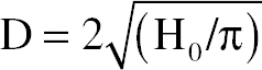
(where H0 is defined under §25.365(e)(2) of this part and D need not exceed 5.05 feet (1.54 meters)). The sphere is applied everywhere within the fuselage—limited by the forward bulkhead and the aft bulkhead of the passenger cabin and cargo compartment beyond which only one-half the sphere is applied.
(ii) Where compliance with paragraph (c)(2)(i) of this section is impracticable, other design precautions must be taken to maximize the survivability of those systems.
(3) Interior design to facilitate searches. Design features must be incorporated that will deter concealment or promote discovery of weapons, explosives, or other objects from a simple inspection in the following areas of the airplane cabin:
(i) Areas above the overhead bins must be designed to prevent objects from being hidden from view in a simple search from the aisle. Designs that prevent concealment of objects with volumes 20 cubic inches and greater satisfy this requirement.
(ii) Toilets must be designed to prevent the passage of solid objects greater than 2.0 inches in diameter.
(iii) Life preservers or their storage locations must be designed so that tampering is evident.
(d) Each chemical oxygen generator or its installation must be designed to be secure from deliberate manipulation by one of the following:
(1) By providing effective resistance to tampering,
(2) By providing an effective combination of resistance to tampering and active tamper-evident features,
(3) By installation in a location or manner whereby any attempt to access the generator would be immediately obvious, or
(4) By a combination of approaches specified in paragraphs (d)(1), (d)(2) and (d)(3) of this section that the Administrator finds provides a secure installation.
(e) Exceptions. Airplanes used solely to transport cargo only need to meet the requirements of paragraphs (b)(1), (b)(3), and (c)(2) of this section.
(f) Material Incorporated by Reference. You must use National Institute of Justice (NIJ) Standard 0101.04, Ballistic Resistance of Personal Body Armor, June 2001, Revision A, to establish ballistic resistance as required by paragraph (a)(3) of this section.
(1) The Director of the Federal Register approved the incorporation by reference of this document under 5 U.S.C. 552(a) and 1 CFR part 51.
(2) You may review copies of NIJ Standard 0101.04 at the:
(i) National Institute of Justice (NIJ), http://www.ojp.usdoj.gov/nij, telephone (202) 307-2942; or
(ii) National Archives and Records Administration (NARA). For information on the availability of this material at NARA, call (202) 741-6030, or go to http://www.archives.gov/federal-register/cfr/ibr-locations.html.
(3) You may obtain copies of NIJ Standard 0101.04 from the National Criminal Justice Reference Service, P.O. Box 6000, Rockville, MD 20849-6000, telephone (800) 851-3420.
[Amdt. 25-127; 121-341, 73 FR 63879, Oct. 28, 2008, as amended at 74 FR 22819, May 15, 2009; Amdt. 25-138, 79 FR 13519, Mar. 11, 2014; Doc. No. FAA-2018-0119, Amdt. 25-145, 83 FR 9169, Mar. 5, 2018]
EMERGENCY PROVISIONS
§25.801 Ditching.
(a) If certification with ditching provisions is requested, the airplane must meet the requirements of this section and §§25.807(e), 25.1411, and 25.1415(a).
(b) Each practicable design measure, compatible with the general characteristics of the airplane, must be taken to minimize the probability that in an emergency landing on water, the behavior of the airplane would cause immediate injury to the occupants or would make it impossible for them to escape.
(c) The probable behavior of the airplane in a water landing must be investigated by model tests or by comparison with airplanes of similar configuration for which the ditching characteristics are known. Scoops, flaps, projections, and any other factor likely to affect the hydrodynamic characteristics of the airplane, must be considered.
(d) It must be shown that, under reasonably probable water conditions, the flotation time and trim of the airplane will allow the occupants to leave the airplane and enter the liferafts required by §25.1415. If compliance with this provision is shown by buoyancy and trim computations, appropriate allowances must be made for probable structural damage and leakage. If the airplane has fuel tanks (with fuel jettisoning provisions) that can reasonably be expected to withstand a ditching without leakage, the jettisonable volume of fuel may be considered as buoyancy volume.
(e) Unless the effects of the collapse of external doors and windows are accounted for in the investigation of the probable behavior of the airplane in a water landing (as prescribed in paragraphs (c) and (d) of this section), the external doors and windows must be designed to withstand the probable maximum local pressures.
[Doc. No. 5066, 29 FR 18291, Dec. 24, 1964, as amended by Amdt. 25-72, 55 FR 29781, July 20, 1990]
§25.803 Emergency evacuation.
(a) Each crew and passenger area must have emergency means to allow rapid evacuation in crash landings, with the landing gear extended as well as with the landing gear retracted, considering the possibility of the airplane being on fire.
(b) [Reserved]
(c) For airplanes having a seating capacity of more than 44 passengers, it must be shown that the maximum seating capacity, including the number of crewmembers required by the operating rules for which certification is requested, can be evacuated from the airplane to the ground under simulated emergency conditions within 90 seconds. Compliance with this requirement must be shown by actual demonstration using the test criteria outlined in appendix J of this part unless the Administrator finds that a combination of analysis and testing will provide data equivalent to that which would be obtained by actual demonstration.
(d)-(e) [Reserved]
[Doc. No. 24344, 55 FR 29781, July 20, 1990]
§25.807 Emergency exits.
(a) Type. For the purpose of this part, the types of exits are defined as follows:
(1) Type I. This type is a floor-level exit with a rectangular opening of not less than 24 inches wide by 48 inches high, with corner radii not greater than eight inches.
(2) Type II. This type is a rectangular opening of not less than 20 inches wide by 44 inches high, with corner radii not greater than seven inches. Type II exits must be floor-level exits unless located over the wing, in which case they must not have a step-up inside the airplane of more than 10 inches nor a step-down outside the airplane of more than 17 inches.
(3) Type III. This type is a rectangular opening of not less than 20 inches wide by 36 inches high with corner radii not greater than seven inches, and with a step-up inside the airplane of not more than 20 inches. If the exit is located over the wing, the step-down outside the airplane may not exceed 27 inches.
(4) Type IV. This type is a rectangular opening of not less than 19 inches wide by 26 inches high, with corner radii not greater than 6.3 inches, located over the wing, with a step-up inside the airplane of not more than 29 inches and a step-down outside the airplane of not more than 36 inches.
(5) Ventral. This type is an exit from the passenger compartment through the pressure shell and the bottom fuselage skin. The dimensions and physical configuration of this type of exit must allow at least the same rate of egress as a Type I exit with the airplane in the normal ground attitude, with landing gear extended.
(6) Tailcone. This type is an aft exit from the passenger compartment through the pressure shell and through an openable cone of the fuselage aft of the pressure shell. The means of opening the tailcone must be simple and obvious and must employ a single operation.
(7) Type A. This type is a floor-level exit with a rectangular opening of not less than 42 inches wide by 72 inches high, with corner radii not greater than seven inches.
(8) Type B. This type is a floor-level exit with a rectangular opening of not less than 32 inches wide by 72 inches high, with corner radii not greater than six inches.
(9) Type C. This type is a floor-level exit with a rectangular opening of not less than 30 inches wide by 48 inches high, with corner radii not greater than 10 inches.
(b) Step down distance. Step down distance, as used in this section, means the actual distance between the bottom of the required opening and a usable foot hold, extending out from the fuselage, that is large enough to be effective without searching by sight or feel.
(c) Over-sized exits. Openings larger than those specified in this section, whether or not of rectangular shape, may be used if the specified rectangular opening can be inscribed within the opening and the base of the inscribed rectangular opening meets the specified step-up and step-down heights.
(d) Asymmetry. Exits of an exit pair need not be diametrically opposite each other nor of the same size; however, the number of passenger seats permitted under paragraph (g) of this section is based on the smaller of the two exits.
(e) Uniformity. Exits must be distributed as uniformly as practical, taking into account passenger seat distribution.
(f) Location. (1) Each required passenger emergency exit must be accessible to the passengers and located where it will afford the most effective means of passenger evacuation.
(2) If only one floor-level exit per side is prescribed, and the airplane does not have a tailcone or ventral emergency exit, the floor-level exits must be in the rearward part of the passenger compartment unless another location affords a more effective means of passenger evacuation.
(3) If more than one floor-level exit per side is prescribed, and the airplane does not have a combination cargo and passenger configuration, at least one floor-level exit must be located in each side near each end of the cabin.
(4) For an airplane that is required to have more than one passenger emergency exit for each side of the fuselage, no passenger emergency exit shall be more than 60 feet from any adjacent passenger emergency exit on the same side of the same deck of the fuselage, as measured parallel to the airplane’s longitudinal axis between the nearest exit edges.
(g) Type and number required. The maximum number of passenger seats permitted depends on the type and number of exits installed in each side of the fuselage. Except as further restricted in paragraphs (g)(1) through (g)(9) of this section, the maximum number of passenger seats permitted for each exit of a specific type installed in each side of the fuselage is as follows:
Type A |
110 |
Type B |
75 |
Type C |
55 |
Type I |
45 |
Type II |
40 |
Type III |
35 |
Type IV |
9 |
(1) For a passenger seating configuration of 1 to 9 seats, there must be at least one Type IV or larger overwing exit in each side of the fuselage or, if overwing exits are not provided, at least one exit in each side that meets the minimum dimensions of a Type III exit.
(2) For a passenger seating configuration of more than 9 seats, each exit must be a Type III or larger exit.
(3) For a passenger seating configuration of 10 to 19 seats, there must be at least one Type III or larger exit in each side of the fuselage.
(4) For a passenger seating configuration of 20 to 40 seats, there must be at least two exits, one of which must be a Type II or larger exit, in each side of the fuselage.
(5) For a passenger seating configuration of 41 to 110 seats, there must be at least two exits, one of which must be a Type I or larger exit, in each side of the fuselage.
(6) For a passenger seating configuration of more than 110 seats, the emergency exits in each side of the fuselage must include at least two Type I or larger exits.
(7) The combined maximum number of passenger seats permitted for all Type III exits is 70, and the combined maximum number of passenger seats permitted for two Type III exits in each side of the fuselage that are separated by fewer than three passenger seat rows is 65.
(8) If a Type A, Type B, or Type C exit is installed, there must be at least two Type C or larger exits in each side of the fuselage.
(9) If a passenger ventral or tailcone exit is installed and that exit provides at least the same rate of egress as a Type III exit with the airplane in the most adverse exit opening condition that would result from the collapse of one or more legs of the landing gear, an increase in the passenger seating configuration is permitted as follows:
(i) For a ventral exit, 12 additional passenger seats.
(ii) For a tailcone exit incorporating a floor level opening of not less than 20 inches wide by 60 inches high, with corner radii not greater than seven inches, in the pressure shell and incorporating an approved assist means in accordance with §25.810(a), 25 additional passenger seats.
(iii) For a tailcone exit incorporating an opening in the pressure shell which is at least equivalent to a Type III emergency exit with respect to dimensions, step-up and step-down distance, and with the top of the opening not less than 56 inches from the passenger compartment floor, 15 additional passenger seats.
(h) Other exits. The following exits also must meet the applicable emergency exit requirements of §§25.809 through 25.812, and must be readily accessible:
(1) Each emergency exit in the passenger compartment in excess of the minimum number of required emergency exits.
(2) Any other floor-level door or exit that is accessible from the passenger compartment and is as large or larger than a Type II exit, but less than 46 inches wide.
(3) Any other ventral or tail cone passenger exit.
(i) Ditching emergency exits for passengers. Whether or not ditching certification is requested, ditching emergency exits must be provided in accordance with the following requirements, unless the emergency exits required by paragraph (g) of this section already meet them:
(1) For airplanes that have a passenger seating configuration of nine or fewer seats, excluding pilot seats, one exit above the waterline in each side of the airplane, meeting at least the dimensions of a Type IV exit.
(2) For airplanes that have a passenger seating configuration of 10 of more seats, excluding pilot seats, one exit above the waterline in a side of the airplane, meeting at least the dimensions of a Type III exit for each unit (or part of a unit) of 35 passenger seats, but no less than two such exits in the passenger cabin, with one on each side of the airplane. The passenger seat/ exit ratio may be increased through the use of larger exits, or other means, provided it is shown that the evacuation capability during ditching has been improved accordingly.
(3) If it is impractical to locate side exits above the waterline, the side exits must be replaced by an equal number of readily accessible overhead hatches of not less than the dimensions of a Type III exit, except that for airplanes with a passenger configuration of 35 or fewer seats, excluding pilot seats, the two required Type III side exits need be replaced by only one overhead hatch.
(j) Flightcrew emergency exits. For airplanes in which the proximity of passenger emergency exits to the flightcrew area does not offer a convenient and readily accessible means of evacuation of the flightcrew, and for all airplanes having a passenger seating capacity greater than 20, flightcrew exits shall be located in the flightcrew area. Such exits shall be of sufficient size and so located as to permit rapid evacuation by the crew. One exit shall be provided on each side of the airplane; or, alternatively, a top hatch shall be provided. Each exit must encompass an unobstructed rectangular opening of at least 19 by 20 inches unless satisfactory exit utility can be demonstrated by a typical crewmember.
[Amdt. 25-72, 55 FR 29781, July 20, 1990, as amended by Amdt. 25-88, 61 FR 57956, Nov. 8, 1996; 62 FR 1817, Jan. 13, 1997; Amdt. 25-94, 63 FR 8848, Feb. 23, 1998; 63 FR 12862, Mar. 16, 1998; Amdt. 25-114, 69 FR 24502, May 3, 2004]
§25.809 Emergency exit arrangement.
(a) Each emergency exit, including each flightcrew emergency exit, must be a moveable door or hatch in the external walls of the fuselage, allowing an unobstructed opening to the outside. In addition, each emergency exit must have means to permit viewing of the conditions outside the exit when the exit is closed. The viewing means may be on or adjacent to the exit provided no obstructions exist between the exit and the viewing means. Means must also be provided to permit viewing of the likely areas of evacuee ground contact. The likely areas of evacuee ground contact must be viewable during all lighting conditions with the landing gear extended as well as in all conditions of landing gear collapse.
(b) Each emergency exit must be openable from the inside and the outside except that sliding window emergency exits in the flight crew area need not be openable from the outside if other approved exits are convenient and readily accessible to the flight crew area. Each emergency exit must be capable of being opened, when there is no fuselage deformation—
(1) With the airplane in the normal ground attitude and in each of the attitudes corresponding to collapse of one or more legs of the landing gear; and
(2) Within 10 seconds measured from the time when the opening means is actuated to the time when the exit is fully opened.
(3) Even though persons may be crowded against the door on the inside of the airplane.
(c) The means of opening emergency exits must be simple and obvious; may not require exceptional effort; and must be arranged and marked so that it can be readily located and operated, even in darkness. Internal exit-opening means involving sequence operations (such as operation of two handles or latches, or the release of safety catches) may be used for flightcrew emergency exits if it can be reasonably established that these means are simple and obvious to crewmembers trained in their use.
(d) If a single power-boost or single power-operated system is the primary system for operating more than one exit in an emergency, each exit must be capable of meeting the requirements of paragraph (b) of this section in the event of failure of the primary system. Manual operation of the exit (after failure of the primary system) is acceptable.
(e) Each emergency exit must be shown by tests, or by a combination of analysis and tests, to meet the requirements of paragraphs (b) and (c) of this section.
(f) Each door must be located where persons using them will not be endangered by the propellers when appropriate operating procedures are used.
(g) There must be provisions to minimize the probability of jamming of the emergency exits resulting from fuselage deformation in a minor crash landing.
(h) When required by the operating rules for any large passenger-carrying turbojet-powered airplane, each ventral exit and tailcone exit must be—
(1) Designed and constructed so that it cannot be opened during flight; and
(2) Marked with a placard readable from a distance of 30 inches and installed at a conspicuous location near the means of opening the exit, stating that the exit has been designed and constructed so that it cannot be opened during flight.
(i) Each emergency exit must have a means to retain the exit in the open position, once the exit is opened in an emergency. The means must not require separate action to engage when the exit is opened, and must require positive action to disengage.
[Doc. No. 5066, 29 FR 18291, Dec. 24, 1964, as amended by Amdt. 25-15, 32 FR 13264, Sept. 20, 1967; Amdt. 25-32, 37 FR 3970, Feb. 24, 1972; Amdt. 25-34, 37 FR 25355, Nov. 30, 1972; Amdt. 25-46, 43 FR 50597, Oct. 30, 1978; Amdt. 25-47, 44 FR 61325, Oct. 25, 1979; Amdt. 25-72, 55 FR 29782, July 20, 1990; Amdt. 25-114, 69 FR 24502, May 3, 2004; Amdt. 25-116, 69 FR 62788, Oct. 27, 2004]
§25.810 Emergency egress assist means and escape routes.
(a) Each non over-wing Type A, Type B or Type C exit, and any other non over-wing landplane emergency exit more than 6 feet from the ground with the airplane on the ground and the landing gear extended, must have an approved means to assist the occupants in descending to the ground.
(1) The assisting means for each passenger emergency exit must be a self-supporting slide or equivalent; and, in the case of Type A or Type B exits, it must be capable of carrying simultaneously two parallel lines of evacuees. In addition, the assisting means must be designed to meet the following requirements—
(i) It must be automatically deployed and deployment must begin during the interval between the time the exit opening means is actuated from inside the airplane and the time the exit is fully opened. However, each passenger emergency exit which is also a passenger entrance door or a service door must be provided with means to prevent deployment of the assisting means when it is opened from either the inside or the outside under nonemergency conditions for normal use.
(ii) Except for assisting means installed at Type C exits, it must be automatically erected within 6 seconds after deployment is begun. Assisting means installed at Type C exits must be automatically erected within 10 seconds from the time the opening means of the exit is actuated.
(iii) It must be of such length after full deployment that the lower end is self-supporting on the ground and provides safe evacuation of occupants to the ground after collapse of one or more legs of the landing gear.
(iv) It must have the capability, in 25-knot winds directed from the most critical angle, to deploy and, with the assistance of only one person, to remain usable after full deployment to evacuate occupants safely to the ground.
(v) For each system installation (mockup or airplane installed), five consecutive deployment and inflation tests must be conducted (per exit) without failure, and at least three tests of each such five-test series must be conducted using a single representative sample of the device. The sample devices must be deployed and inflated by the system’s primary means after being subjected to the inertia forces specified in §25.561(b). If any part of the system fails or does not function properly during the required tests, the cause of the failure or malfunction must be corrected by positive means and after that, the full series of five consecutive deployment and inflation tests must be conducted without failure.
(2) The assisting means for flightcrew emergency exits may be a rope or any other means demonstrated to be suitable for the purpose. If the assisting means is a rope, or an approved device equivalent to a rope, it must be—
(i) Attached to the fuselage structure at or above the top of the emergency exit opening, or, for a device at a pilot’s emergency exit window, at another approved location if the stowed device, or its attachment, would reduce the pilot’s view in flight;
(ii) Able (with its attachment) to withstand a 400-pound static load.
(b) Assist means from the cabin to the wing are required for each type A or Type B exit located above the wing and having a stepdown unless the exit without an assist-means can be shown to have a rate of passenger egress at least equal to that of the same type of non over-wing exit. If an assist means is required, it must be automatically deployed and automatically erected concurrent with the opening of the exit. In the case of assist means installed at Type C exits, it must be self-supporting within 10 seconds from the time the opening means of the exits is actuated. For all other exit types, it must be self-supporting 6 seconds after deployment is begun.
(c) An escape route must be established from each overwing emergency exit, and (except for flap surfaces suitable as slides) covered with a slip resistant surface. Except where a means for channeling the flow of evacuees is provided—
(1) The escape route from each Type A or Type B passenger emergency exit, or any common escape route from two Type III passenger emergency exits, must be at least 42 inches wide; that from any other passenger emergency exit must be at least 24 inches wide; and
(2) The escape route surface must have a reflectance of at least 80 percent, and must be defined by markings with a surface-to-marking contrast ratio of at least 5:1.
(d) Means must be provided to assist evacuees to reach the ground for all Type C exits located over the wing and, if the place on the airplane structure at which the escape route required in paragraph (c) of this section terminates is more than 6 feet from the ground with the airplane on the ground and the landing gear extended, for all other exit types.
(1) If the escape route is over the flap, the height of the terminal edge must be measured with the flap in the takeoff or landing position, whichever is higher from the ground.
(2) The assisting means must be usable and self-supporting with one or more landing gear legs collapsed and under a 25-knot wind directed from the most critical angle.
(3) The assisting means provided for each escape route leading from a Type A or B emergency exit must be capable of carrying simultaneously two parallel lines of evacuees; and, the assisting means leading from any other exit type must be capable of carrying as many parallel lines of evacuees as there are required escape routes.
(4) The assisting means provided for each escape route leading from a Type C exit must be automatically erected within 10 seconds from the time the opening means of the exit is actuated, and that provided for the escape route leading from any other exit type must be automatically erected within 10 seconds after actuation of the erection system.
(e) If an integral stair is installed in a passenger entry door that is qualified as a passenger emergency exit, the stair must be designed so that, under the following conditions, the effectiveness of passenger emergency egress will not be impaired:
(1) The door, integral stair, and operating mechanism have been subjected to the inertia forces specified in §25.561(b)(3), acting separately relative to the surrounding structure.
(2) The airplane is in the normal ground attitude and in each of the attitudes corresponding to collapse of one or more legs of the landing gear.
[Amdt. 25-72, 55 FR 29782, July 20, 1990, as amended by Amdt. 25-88, 61 FR 57958, Nov. 8, 1996; 62 FR 1817, Jan. 13, 1997; Amdt. 25-114, 69 FR 24502, May 3, 2004]
§25.811 Emergency exit marking.
(a) Each passenger emergency exit, its means of access, and its means of opening must be conspicuously marked.
(b) The identity and location of each passenger emergency exit must be recognizable from a distance equal to the width of the cabin.
(c) Means must be provided to assist the occupants in locating the exits in conditions of dense smoke.
(d) The location of each passenger emergency exit must be indicated by a sign visible to occupants approaching along the main passenger aisle (or aisles). There must be—
(1) A passenger emergency exit locator sign above the aisle (or aisles) near each passenger emergency exit, or at another overhead location if it is more practical because of low headroom, except that one sign may serve more than one exit if each exit can be seen readily from the sign;
(2) A passenger emergency exit marking sign next to each passenger emergency exit, except that one sign may serve two such exits if they both can be seen readily from the sign; and
(3) A sign on each bulkhead or divider that prevents fore and aft vision along the passenger cabin to indicate emergency exits beyond and obscured by the bulkhead or divider, except that if this is not possible the sign may be placed at another appropriate location.
(e) The location of the operating handle and instructions for opening exits from the inside of the airplane must be shown in the following manner:
(1) Each passenger emergency exit must have, on or near the exit, a marking that is readable from a distance of 30 inches.
(2) Each Type A, Type B, Type C or Type I passenger emergency exit operating handle must—
(i) Be self-illuminated with an initial brightness of at least 160 microlamberts; or
(ii) Be conspicuously located and well illuminated by the emergency lighting even in conditions of occupant crowding at the exit.
(3) [Reserved]
(4) Each Type A, Type B, Type C, Type I, or Type II passenger emergency exit with a locking mechanism released by rotary motion of the handle must be marked—
(i) With a red arrow, with a shaft at least three-fourths of an inch wide and a head twice the width of the shaft, extending along at least 70 degrees of arc at a radius approximately equal to three-fourths of the handle length.
(ii) So that the centerline of the exit handle is within ±1 inch of the projected point of the arrow when the handle has reached full travel and has released the locking mechanism, and
(iii) With the word “open” in red letters 1 inch high, placed horizontally near the head of the arrow.
(f) Each emergency exit that is required to be openable from the outside, and its means of opening, must be marked on the outside of the airplane. In addition, the following apply:
(1) The outside marking for each passenger emergency exit in the side of the fuselage must include a 2-inch colored band outlining the exit.
(2) Each outside marking including the band, must have color contrast to be readily distinguishable from the surrounding fuselage surface. The contrast must be such that if the reflectance of the darker color is 15 percent or less, the reflectance of the lighter color must be at least 45 percent. “Reflectance” is the ratio of the luminous flux reflected by a body to the luminous flux it receives. When the reflectance of the darker color is greater than 15 percent, at least a 30-percent difference between its reflectance and the reflectance of the lighter color must be provided.
(3) In the case of exists other than those in the side of the fuselage, such as ventral or tailcone exists, the external means of opening, including instructions if applicable, must be conspicuously marked in red, or bright chrome yellow if the background color is such that red is inconspicuous. When the opening means is located on only one side of the fuselage, a conspicuous marking to that effect must be provided on the other side.
(g) Each sign required by paragraph (d) of this section may use the word “exit” in its legend in place of the term “emergency exit”.
[Amdt. 25-15, 32 FR 13264, Sept. 20, 1967, as amended by Amdt. 25-32, 37 FR 3970, Feb. 24, 1972; Amdt. 25-46, 43 FR 50597, Oct. 30, 1978; 43 FR 52495, Nov. 13, 1978; Amdt. 25-79, 58 FR 45229, Aug. 26, 1993; Amdt. 25-88, 61 FR 57958, Nov. 8, 1996]
§25.812 Emergency lighting.
(a) An emergency lighting system, independent of the main lighting system, must be installed. However, the sources of general cabin illumination may be common to both the emergency and the main lighting systems if the power supply to the emergency lighting system is independent of the power supply to the main lighting system. The emergency lighting system must include:
(1) Illuminated emergency exit marking and locating signs, sources of general cabin illumination, interior lighting in emergency exit areas, and floor proximity escape path marking.
(2) Exterior emergency lighting.
(b) Emergency exit signs—
(1) For airplanes that have a passenger seating configuration, excluding pilot seats, of 10 seats or more must meet the following requirements:
(i) Each passenger emergency exit locator sign required by §25.811(d)(1) and each passenger emergency exit marking sign required by §25.811(d)(2) must have red letters at least 11⁄2 inches high on an illuminated white background, and must have an area of at least 21 square inches excluding the letters. The lighted background-to-letter contrast must be at least 10:1. The letter height to stroke-width ratio may not be more than 7:1 nor less than 6:1. These signs must be internally electrically illuminated with a background brightness of at least 25 foot-lamberts and a high-to-low background contrast no greater than 3:1.
(ii) Each passenger emergency exit sign required by §25.811(d)(3) must have red letters at least 11⁄2 inches high on a white background having an area of at least 21 square inches excluding the letters. These signs must be internally electrically illuminated or self-illuminated by other than electrical means and must have an initial brightness of at least 400 microlamberts. The colors may be reversed in the case of a sign that is self-illuminated by other than electrical means.
(2) For airplanes that have a passenger seating configuration, excluding pilot seats, of nine seats or less, that are required by §25.811(d)(1), (2), and (3) must have red letters at least 1 inch high on a white background at least 2 inches high. These signs may be internally electrically illuminated, or self-illuminated by other than electrical means, with an initial brightness of at least 160 microlamberts. The colors may be reversed in the case of a sign that is self-illuminated by other than electrical means.
(c) General illumination in the passenger cabin must be provided so that when measured along the centerline of main passenger aisle(s), and cross aisle(s) between main aisles, at seat arm-rest height and at 40-inch intervals, the average illumination is not less than 0.05 foot-candle and the illumination at each 40-inch interval is not less than 0.01 foot-candle. A main passenger aisle(s) is considered to extend along the fuselage from the most forward passenger emergency exit or cabin occupant seat, whichever is farther forward, to the most rearward passenger emergency exit or cabin occupant seat, whichever is farther aft.
(d) The floor of the passageway leading to each floor-level passenger emergency exit, between the main aisles and the exit openings, must be provided with illumination that is not less than 0.02 foot-candle measured along a line that is within 6 inches of and parallel to the floor and is centered on the passenger evacuation path.
(e) Floor proximity emergency escape path marking must provide emergency evacuation guidance for passengers when all sources of illumination more than 4 feet above the cabin aisle floor are totally obscured. In the dark of the night, the floor proximity emergency escape path marking must enable each passenger to—
(1) After leaving the passenger seat, visually identify the emergency escape path along the cabin aisle floor to the first exits or pair of exits forward and aft of the seat; and
(2) Readily identify each exit from the emergency escape path by reference only to markings and visual features not more than 4 feet above the cabin floor.
(f) Except for subsystems provided in accordance with paragraph (h) of this section that serve no more than one assist means, are independent of the airplane’s main emergency lighting system, and are automatically activated when the assist means is erected, the emergency lighting system must be designed as follows.
(1) The lights must be operable manually from the flight crew station and from a point in the passenger compartment that is readily accessible to a normal flight attendant seat.
(2) There must be a flight crew warning light which illuminates when power is on in the airplane and the emergency lighting control device is not armed.
(3) The cockpit control device must have an “on,” “off,” and “armed” position so that when armed in the cockpit or turned on at either the cockpit or flight attendant station the lights will either light or remain lighted upon interruption (except an interruption caused by a transverse vertical separation of the fuselage during crash landing) of the airplane’s normal electric power. There must be a means to safeguard against inadvertent operation of the control device from the “armed” or “on” positions.
(g) Exterior emergency lighting must be provided as follows:
(1) At each overwing emergency exit the illumination must be—
(i) Not less than 0.03 foot-candle (measured normal to the direction of the incident light) on a 2-square-foot area where an evacuee is likely to make his first step outside the cabin;
(ii) Not less than 0.05 foot-candle (measured normal to the direction of the incident light) for a minimum width of 42 inches for a Type A overwing emergency exit and two feet for all other overwing emergency exits along the 30 percent of the slip-resistant portion of the escape route required in §25.810(c) that is farthest from the exit; and
(iii) Not less than 0.03 foot-candle on the ground surface with the landing gear extended (measured normal to the direction of the incident light) where an evacuee using the established escape route would normally make first contact with the ground.
(2) At each non-overwing emergency exit not required by §25.810(a) to have descent assist means the illumination must be not less than 0.03 foot-candle (measured normal to the direction of the incident light) on the ground surface with the landing gear extended where an evacuee is likely to make first contact with the ground outside the cabin.
(h) The means required in §§25.810(a)(1) and (d) to assist the occupants in descending to the ground must be illuminated so that the erected assist means is visible from the airplane.
(1) If the assist means is illuminated by exterior emergency lighting, it must provide illumination of not less than 0.03 foot-candle (measured normal to the direction of the incident light) at the ground end of the erected assist means where an evacuee using the established escape route would normally make first contact with the ground, with the airplane in each of the attitudes corresponding to the collapse of one or more legs of the landing gear.
(2) If the emergency lighting subsystem illuminating the assist means serves no other assist means, is independent of the airplane’s main emergency lighting system, and is automatically activated when the assist means is erected, the lighting provisions—
(i) May not be adversely affected by stowage; and
(ii) Must provide illumination of not less than 0.03 foot-candle (measured normal to the direction of incident light) at the ground and of the erected assist means where an evacuee would normally make first contact with the ground, with the airplane in each of the attitudes corresponding to the collapse of one or more legs of the landing gear.
(i) The energy supply to each emergency lighting unit must provide the required level of illumination for at least 10 minutes at the critical ambient conditions after emergency landing.
(j) If storage batteries are used as the energy supply for the emergency lighting system, they may be recharged from the airplane’s main electric power system: Provided, That, the charging circuit is designed to preclude inadvertent battery discharge into charging circuit faults.
(k) Components of the emergency lighting system, including batteries, wiring relays, lamps, and switches must be capable of normal operation after having been subjected to the inertia forces listed in §25.561(b).
(l) The emergency lighting system must be designed so that after any single transverse vertical separation of the fuselage during crash landing—
(1) Not more than 25 percent of all electrically illuminated emergency lights required by this section are rendered inoperative, in addition to the lights that are directly damaged by the separation;
(2) Each electrically illuminated exit sign required under §25.811(d)(2) remains operative exclusive of those that are directly damaged by the separation; and
(3) At least one required exterior emergency light for each side of the airplane remains operative exclusive of those that are directly damaged by the separation.
[Amdt. 25-15, 32 FR 13265, Sept. 20, 1967, as amended by Amdt. 25-28, 36 FR 16899, Aug. 26, 1971; Amdt. 25-32, 37 FR 3971, Feb. 24, 1972; Amdt. 25-46, 43 FR 50597, Oct. 30, 1978; Amdt. 25-58, 49 FR 43186, Oct. 26, 1984; Amdt. 25-88, 61 FR 57958, Nov. 8, 1996; Amdt. 25-116, 69 FR 62788, Oct. 27, 2004; Amdt. 25-128, 74 FR 25645, May 29, 2009]
§25.813 Emergency exit access.
Each required emergency exit must be accessible to the passengers and located where it will afford an effective means of evacuation. Emergency exit distribution must be as uniform as practical, taking passenger distribution into account; however, the size and location of exits on both sides of the cabin need not be symmetrical. If only one floor level exit per side is prescribed, and the airplane does not have a tailcone or ventral emergency exit, the floor level exit must be in the rearward part of the passenger compartment, unless another location affords a more effective means of passenger evacuation. Where more than one floor level exit per side is prescribed, at least one floor level exit per side must be located near each end of the cabin, except that this provision does not apply to combination cargo/passenger configurations. In addition—
(a) There must be a passageway leading from the nearest main aisle to each Type A, Type B, Type C, Type I, or Type II emergency exit and between individual passenger areas. Each passageway leading to a Type A or Type B exit must be unobstructed and at least 36 inches wide. Passageways between individual passenger areas and those leading to Type I, Type II, or Type C emergency exits must be unobstructed and at least 20 inches wide. Unless there are two or more main aisles, each Type A or B exit must be located so that there is passenger flow along the main aisle to that exit from both the forward and aft directions. If two or more main aisles are provided, there must be unobstructed cross-aisles at least 20 inches wide between main aisles. There must be—
(1) A cross-aisle which leads directly to each passageway between the nearest main aisle and a Type A or B exit; and
(2) A cross-aisle which leads to the immediate vicinity of each passageway between the nearest main aisle and a Type 1, Type II, or Type III exit; except that when two Type III exits are located within three passenger rows of each other, a single cross-aisle may be used if it leads to the vicinity between the passageways from the nearest main aisle to each exit.
(b) Adequate space to allow crewmember(s) to assist in the evacuation of passengers must be provided as follows:
(1) Each assist space must be a rectangle on the floor, of sufficient size to enable a crewmember, standing erect, to effectively assist evacuees. The assist space must not reduce the unobstructed width of the passageway below that required for the exit.
(2) For each Type A or B exit, assist space must be provided at each side of the exit regardless of whether an assist means is required by §25.810(a).
(3) For each Type C, I or II exit installed in an airplane with seating for more than 80 passengers, an assist space must be provided at one side of the passageway regardless of whether an assist means is required by §25.810(a).
(4) For each Type C, I or II exit, an assist space must be provided at one side of the passageway if an assist means is required by §25.810(a).
(5) For any tailcone exit that qualifies for 25 additional passenger seats under the provisions of §25.807(g)(9)(ii), an assist space must be provided, if an assist means is required by §25.810(a).
(6) There must be a handle, or handles, at each assist space, located to enable the crewmember to steady himself or herself:
(i) While manually activating the assist means (where applicable) and,
(ii) While assisting passengers during an evacuation.
(c) The following must be provided for each Type III or Type IV exit—(1) There must be access from the nearest aisle to each exit. In addition, for each Type III exit in an airplane that has a passenger seating configuration of 60 or more—
(i) Except as provided in paragraph (c)(1)(ii), the access must be provided by an unobstructed passageway that is at least 10 inches in width for interior arrangements in which the adjacent seat rows on the exit side of the aisle contain no more than two seats, or 20 inches in width for interior arrangements in which those rows contain three seats. The width of the passageway must be measured with adjacent seats adjusted to their most adverse position. The centerline of the required passageway width must not be displaced more than 5 inches horizontally from that of the exit.
(ii) In lieu of one 10- or 20-inch passageway, there may be two passageways, between seat rows only, that must be at least 6 inches in width and lead to an unobstructed space adjacent to each exit. (Adjacent exits must not share a common passageway.) The width of the passageways must be measured with adjacent seats adjusted to their most adverse position. The unobstructed space adjacent to the exit must extend vertically from the floor to the ceiling (or bottom of sidewall stowage bins), inboard from the exit for a distance not less than the width of the narrowest passenger seat installed on the airplane, and from the forward edge of the forward passageway to the aft edge of the aft passageway. The exit opening must be totally within the fore and aft bounds of the unobstructed space.
(2) In addition to the access—
(i) For airplanes that have a passenger seating configuration of 20 or more, the projected opening of the exit provided must not be obstructed and there must be no interference in opening the exit by seats, berths, or other protrusions (including any seatback in the most adverse position) for a distance from that exit not less than the width of the narrowest passenger seat installed on the airplane.
(ii) For airplanes that have a passenger seating configuration of 19 or fewer, there may be minor obstructions in this region, if there are compensating factors to maintain the effectiveness of the exit.
(3) For each Type III exit, regardless of the passenger capacity of the airplane in which it is installed, there must be placards that—
(i) Are readable by all persons seated adjacent to and facing a passageway to the exit;
(ii) Accurately state or illustrate the proper method of opening the exit, including the use of handholds; and
(iii) If the exit is a removable hatch, state the weight of the hatch and indicate an appropriate location to place the hatch after removal.
(d) If it is necessary to pass through a passageway between passenger compartments to reach any required emergency exit from any seat in the passenger cabin, the passageway must be unobstructed. However, curtains may be used if they allow free entry through the passageway.
(e) No door may be installed between any passenger seat that is occupiable for takeoff and landing and any passenger emergency exit, such that the door crosses any egress path (including aisles, crossaisles and passageways).
(f) If it is necessary to pass through a doorway separating any crewmember seat (except those seats on the flightdeck), occupiable for takeoff and landing, from any emergency exit, the door must have a means to latch it in the open position. The latching means must be able to withstand the loads imposed upon it when the door is subjected to the ultimate inertia forces, relative to the surrounding structure, listed in §25.561(b).
[Amdt. 25-1, 30 FR 3204, Mar. 9, 1965, as amended by Amdt. 25-15, 32 FR 13265, Sept. 20, 1967; Amdt. 25-32, 37 FR 3971, Feb. 24, 1972; Amdt. 25-46, 43 FR 50597, Oct. 30, 1978; Amdt. 25-72, 55 FR 29783, July 20, 1990; Amdt. 25-76, 57 FR 19244, May 4, 1992; Amdt. 25-76, 57 FR 29120, June 30, 1992; Amdt. 25-88, 61 FR 57958, Nov. 8, 1996; Amdt. 25-116, 69 FR 62788, Oct. 27, 2004; Amdt. 25-128, 74 FR 25645, May 29, 2009]
§25.815 Width of aisle.
The passenger aisle width at any point between seats must equal or exceed the values in the following table:
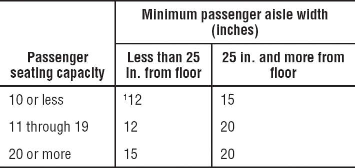
1A narrower width not less than 9 inches may be approved when substantiated by tests found necessary by the Administrator.
[Amdt. 25-15, 32 FR 13265, Sept. 20, 1967, as amended by Amdt. 25-38, 41 FR 55466, Dec. 20, 1976]
§25.817 Maximum number of seats abreast.
On airplanes having only one passenger aisle, no more than three seats abreast may be placed on each side of the aisle in any one row.
[Amdt. 25-15, 32 FR 13265, Sept. 20, 1967]
§25.819 Lower deck service compartments (including galleys).
For airplanes with a service compartment located below the main deck, which may be occupied during taxi or flight but not during takeoff or landing, the following apply:
(a) There must be at least two emergency evacuation routes, one at each end of each lower deck service compartment or two having sufficient separation within each compartment, which could be used by each occupant of the lower deck service compartment to rapidly evacuate to the main deck under normal and emergency lighting conditions. The routes must provide for the evacuation of incapacitated persons, with assistance. The use of the evacuation routes may not be dependent on any powered device. The routes must be designed to minimize the possibility of blockage which might result from fire, mechanical or structural failure, or persons standing on top of or against the escape routes. In the event the airplane’s main power system or compartment main lighting system should fail, emergency illumination for each lower deck service compartment must be automatically provided.
(b) There must be a means for two-way voice communication between the flight deck and each lower deck service compartment, which remains available following loss of normal electrical power generating system.
(c) There must be an aural emergency alarm system, audible during normal and emergency conditions, to enable crewmembers on the flight deck and at each required floor level emergency exit to alert occupants of each lower deck service compartment of an emergency situation.
(d) There must be a means, readily detectable by occupants of each lower deck service compartment, that indicates when seat belts should be fastened.
(e) If a public address system is installed in the airplane, speakers must be provided in each lower deck service compartment.
(f) For each occupant permitted in a lower deck service compartment, there must be a forward or aft facing seat which meets the requirements of §25.785(d), and must be able to withstand maximum flight loads when occupied.
(g) For each powered lift system installed between a lower deck service compartment and the main deck for the carriage of persons or equipment, or both, the system must meet the following requirements:
(1) Each lift control switch outside the lift, except emergency stop buttons, must be designed to prevent the activation of the life if the lift door, or the hatch required by paragraph (g)(3) of this section, or both are open.
(2) An emergency stop button, that when activated will immediately stop the lift, must be installed within the lift and at each entrance to the lift.
(3) There must be a hatch capable of being used for evacuating persons from the lift that is openable from inside and outside the lift without tools, with the lift in any position.
[Amdt. 25-53, 45 FR 41593, June 19, 1980; 45 FR 43154, June 26, 1980; Amdt. 25-110; 68 FR 36883, June 19, 2003]
§25.820 Lavatory doors.
All lavatory doors must be designed to preclude anyone from becoming trapped inside the lavatory. If a locking mechanism is installed, it must be capable of being unlocked from the outside without the aid of special tools.
[Doc. No. 2003-14193, 69 FR 24502, May 3, 2004]
VENTILATION AND HEATING
§25.831 Ventilation.
(a) Under normal operating conditions and in the event of any probable failure conditions of any system which would adversely affect the ventilating air, the ventilation system must be designed to provide a sufficient amount of uncontaminated air to enable the crewmembers to perform their duties without undue discomfort or fatigue and to provide reasonable passenger comfort. For normal operating conditions, the ventilation system must be designed to provide each occupant with an airflow containing at least 0.55 pounds of fresh air per minute.
(b) Crew and passenger compartment air must be free from harmful or hazardous concentrations of gases or vapors. In meeting this requirement, the following apply:
(1) Carbon monoxide concentrations in excess of 1 part in 20,000 parts of air are considered hazardous. For test purposes, any acceptable carbon monoxide detection method may be used.
(2) Carbon dioxide concentration during flight must be shown not to exceed 0.5 percent by volume (sea level equivalent) in compartments normally occupied by passengers or crewmembers.
(c) There must be provisions made to ensure that the conditions prescribed in paragraph (b) of this section are met after reasonably probable failures or malfunctioning of the ventilating, heating, pressurization, or other systems and equipment.
(d) If accumulation of hazardous quantities of smoke in the cockpit area is reasonably probable, smoke evacuation must be readily accomplished, starting with full pressurization and without depressurizing beyond safe limits.
(e) Except as provided in paragraph (f) of this section, means must be provided to enable the occupants of the following compartments and areas to control the temperature and quantity of ventilating air supplied to their compartment or area independently of the temperature and quantity of air supplied to other compartments and areas:
(1) The flight crew compartment.
(2) Crewmember compartments and areas other than the flight crew compartment unless the crewmember compartment or area is ventilated by air interchange with other compartments or areas under all operating conditions.
(f) Means to enable the flight crew to control the temperature and quantity of ventilating air supplied to the flight crew compartment independently of the temperature and quantity of ventilating air supplied to other compartments are not required if all of the following conditions are met:
(1) The total volume of the flight crew and passenger compartments is 800 cubic feet or less.
(2) The air inlets and passages for air to flow between flight crew and passenger compartments are arranged to provide compartment temperatures within 5 degrees F. of each other and adequate ventilation to occupants in both compartments.
(3) The temperature and ventilation controls are accessible to the flight crew.
(g) The exposure time at any given temperature must not exceed the values shown in the following graph after any improbable failure condition.
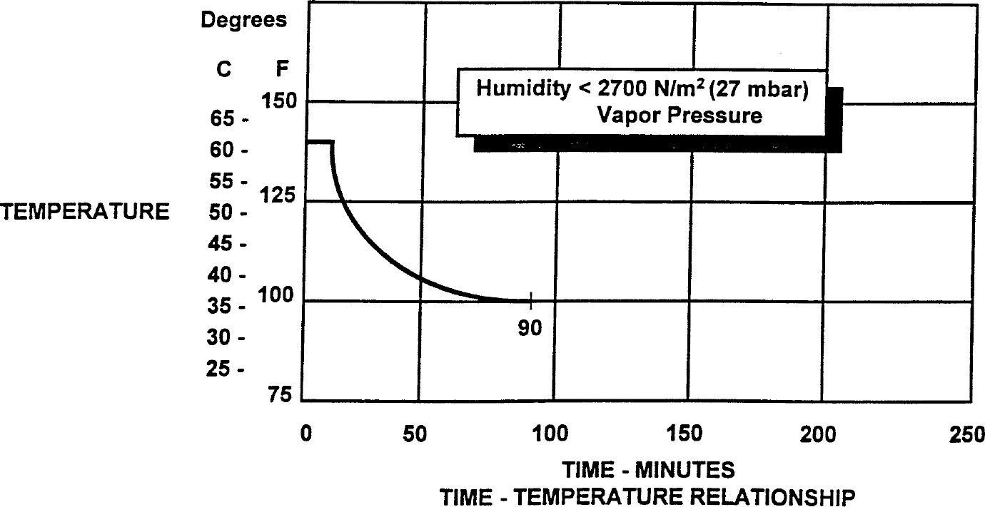
[Doc. No. 5066, 29 FR 18291, Dec. 24, 1964, as amended by Amdt. 25-41, 42 FR 36970, July 18, 1977; Amdt. 25-87, 61 FR 28695, June 5, 1996; Amdt. 25-89, 61 FR 63956, Dec. 2, 1996]
§25.832 Cabin ozone concentration.
(a) The airplane cabin ozone concentration during flight must be shown not to exceed—
(1) 0.25 parts per million by volume, sea level equivalent, at any time above flight level 320; and
(2) 0.1 parts per million by volume, sea level equivalent, time-weighted average during any 3-hour interval above flight level 270.
(b) For the purpose of this section, “sea level equivalent” refers to conditions of 25 °C and 760 millimeters of mercury pressure.
(c) Compliance with this section must be shown by analysis or tests based on airplane operational procedures and performance limitations, that demonstrate that either—
(1) The airplane cannot be operated at an altitude which would result in cabin ozone concentrations exceeding the limits prescribed by paragraph (a) of this section; or
(2) The airplane ventilation system, including any ozone control equipment, will maintain cabin ozone concentrations at or below the limits prescribed by paragraph (a) of this section.
[Amdt. 25-50, 45 FR 3883, Jan. 1, 1980, as amended by Amdt. 25-56, 47 FR 58489, Dec. 30, 1982; Amdt. 25-94, 63 FR 8848, Feb. 23, 1998]
§25.833 Combustion heating systems.
Combustion heaters must be approved.
[Amdt. 25-72, 55 FR 29783, July 20, 1990]
PRESSURIZATION
§25.841 Pressurized cabins.
(a) Pressurized cabins and compartments to be occupied must be equipped to provide a cabin pressure altitude of not more than 8,000 feet at the maximum operating altitude of the airplane under normal operating conditions.
(1) If certification for operation above 25,000 feet is requested, the airplane must be designed so that occupants will not be exposed to cabin pressure altitudes in excess of 15,000 feet after any probable failure condition in the pressurization system.
(2) The airplane must be designed so that occupants will not be exposed to a cabin pressure altitude that exceeds the following after decompression from any failure condition not shown to be extremely improbable:
(i) Twenty-five thousand (25,000) feet for more than 2 minutes; or
(ii) Forty thousand (40,000) feet for any duration.
(3) Fuselage structure, engine and system failures are to be considered in evaluating the cabin decompression.
(b) Pressurized cabins must have at least the following valves, controls, and indicators for controlling cabin pressure:
(1) Two pressure relief valves to automatically limit the positive pressure differential to a predetermined value at the maximum rate of flow delivered by the pressure source. The combined capacity of the relief valves must be large enough so that the failure of any one valve would not cause an appreciable rise in the pressure differential. The pressure differential is positive when the internal pressure is greater than the external.
(2) Two reverse pressure differential relief valves (or their equivalents) to automatically prevent a negative pressure differential that would damage the structure. One valve is enough, however, if it is of a design that reasonably precludes its malfunctioning.
(3) A means by which the pressure differential can be rapidly equalized.
(4) An automatic or manual regulator for controlling the intake or exhaust airflow, or both, for maintaining the required internal pressures and airflow rates.
(5) Instruments at the pilot or flight engineer station to show the pressure differential, the cabin pressure altitude, and the rate of change of the cabin pressure altitude.
(6) Warning indication at the pilot or flight engineer station to indicate when the safe or preset pressure differential and cabin pressure altitude limits are exceeded. Appropriate warning markings on the cabin pressure differential indicator meet the warning requirement for pressure differential limits and an aural or visual signal (in addition to cabin altitude indicating means) meets the warning requirement for cabin pressure altitude limits if it warns the flight crew when the cabin pressure altitude exceeds 10,000 feet.
(7) A warning placard at the pilot or flight engineer station if the structure is not designed for pressure differentials up to the maximum relief valve setting in combination with landing loads.
(8) The pressure sensors necessary to meet the requirements of paragraphs (b)(5) and (b)(6) of this section and §25.1447(c), must be located and the sensing system designed so that, in the event of loss of cabin pressure in any passenger or crew compartment (including upper and lower lobe galleys), the warning and automatic presentation devices, required by those provisions, will be actuated without any delay that would significantly increase the hazards resulting from decompression.
[Doc. No. 5066, 29 FR 18291, Dec. 24, 1964, as amended by Amdt. 25-38, 41 FR 55466, Dec. 20, 1976; Amdt. 25-87, 61 FR 28696, June 5, 1996]
§25.843 Tests for pressurized cabins.
(a) Strength test. The complete pressurized cabin, including doors, windows, and valves, must be tested as a pressure vessel for the pressure differential specified in §25.365(d).
(b) Functional tests. The following functional tests must be performed:
(1) Tests of the functioning and capacity of the positive and negative pressure differential valves, and of the emergency release valve, to stimulate the effects of closed regulator valves.
(2) Tests of the pressurization system to show proper functioning under each possible condition of pressure, temperature, and moisture, up to the maximum altitude for which certification is requested.
(3) Flight tests, to show the performance of the pressure supply, pressure and flow regulators, indicators, and warning signals, in steady and stepped climbs and descents at rates corresponding to the maximum attainable within the operating limitations of the airplane, up to the maximum altitude for which certification is requested.
(4) Tests of each door and emergency exit, to show that they operate properly after being subjected to the flight tests prescribed in paragraph (b)(3) of this section.
FIRE PROTECTION
§25.851 Fire extinguishers.
(a) Hand fire extinguishers. (1) The following minimum number of hand fire extinguishers must be conveniently located and evenly distributed in passenger compartments:
Passenger capacity |
No. of extinguishers |
7 through 30 |
1 |
31 through 60 |
2 |
61 through 200 |
3 |
201 through 300 |
4 |
301 through 400 |
5 |
401 through 500 |
6 |
501 through 600 |
7 |
601 through 700 |
8 |
(2) At least one hand fire extinguisher must be conveniently located in the pilot compartment.
(3) At least one readily accessible hand fire extinguisher must be available for use in each Class A or Class B cargo or baggage compartment and in each Class E or Class F cargo or baggage compartment that is accessible to crewmembers in flight.
(4) At least one hand fire extinguisher must be located in, or readily accessible for use in, each galley located above or below the passenger compartment.
(5) Each hand fire extinguisher must be approved.
(6) At least one of the required fire extinguishers located in the passenger compartment of an airplane with a passenger capacity of at least 31 and not more than 60, and at least two of the fire extinguishers located in the passenger compartment of an airplane with a passenger capacity of 61 or more must contain Halon 1211 (bromochlorodifluoromethane CBrC1 F2), or equivalent, as the extinguishing agent. The type of extinguishing agent used in any other extinguisher required by this section must be appropriate for the kinds of fires likely to occur where used.
(7) The quantity of extinguishing agent used in each extinguisher required by this section must be appropriate for the kinds of fires likely to occur where used.
(8) Each extinguisher intended for use in a personnel compartment must be designed to minimize the hazard of toxic gas concentration.
(b) Built-in fire extinguishers. If a built-in fire extinguisher is provided—
(1) Each built-in fire extinguishing system must be installed so that—
(i) No extinguishing agent likely to enter personnel compartments will be hazardous to the occupants; and
(ii) No discharge of the extinguisher can cause structural damage.
(2) The capacity of each required built-in fire extinguishing system must be adequate for any fire likely to occur in the compartment where used, considering the volume of the compartment and the ventilation rate. The capacity of each system is adequate if there is sufficient quantity of agent to extinguish the fire or suppress the fire anywhere baggage or cargo is placed within the cargo compartment for the duration required to land and evacuate the airplane.
[Amdt. 25-74, 56 FR 15456, Apr. 16, 1991, as amended by Doc. No. Docket FAA-2014-0001, Amdt. 25-142, 81 FR 7703, Feb. 16, 2016]
§25.853 Compartment interiors.
For each compartment occupied by the crew or passengers, the following apply:
(a) Materials (including finishes or decorative surfaces applied to the materials) must meet the applicable test criteria prescribed in part I of appendix F of this part, or other approved equivalent methods, regardless of the passenger capacity of the airplane.
(b) [Reserved]
(c) In addition to meeting the requirements of paragraph (a) of this section, seat cushions, except those on flight crewmember seats, must meet the test requirements of part II of appendix F of this part, or other equivalent methods, regardless of the passenger capacity of the airplane.
(d) Except as provided in paragraph (e) of this section, the following interior components of airplanes with passenger capacities of 20 or more must also meet the test requirements of parts IV and V of appendix F of this part, or other approved equivalent method, in addition to the flammability requirements prescribed in paragraph (a) of this section:
(1) Interior ceiling and wall panels, other than lighting lenses and windows;
(2) Partitions, other than transparent panels needed to enhance cabin safety;
(3) Galley structure, including exposed surfaces of stowed carts and standard containers and the cavity walls that are exposed when a full complement of such carts or containers is not carried; and
(4) Large cabinets and cabin stowage compartments, other than underseat stowage compartments for stowing small items such as magazines and maps.
(e) The interiors of compartments, such as pilot compartments, galleys, lavatories, crew rest quarters, cabinets and stowage compartments, need not meet the standards of paragraph (d) of this section, provided the interiors of such compartments are isolated from the main passenger cabin by doors or equivalent means that would normally be closed during an emergency landing condition.
(f) Smoking is not allowed in lavatories. If smoking is allowed in any area occupied by the crew or passengers, an adequate number of self-contained, removable ashtrays must be provided in designated smoking sections for all seated occupants.
(g) Regardless of whether smoking is allowed in any other part of the airplane, lavatories must have self-contained, removable ashtrays located conspicuously on or near the entry side of each lavatory door, except that one ashtray may serve more than one lavatory door if the ashtray can be seen readily from the cabin side of each lavatory served.
(h) Each receptacle used for the disposal of flammable waste material must be fully enclosed, constructed of at least fire resistant materials, and must contain fires likely to occur in it under normal use. The capability of the receptacle to contain those fires under all probable conditions of wear, misalignment, and ventilation expected in service must be demonstrated by test.
[Amdt. 25-83, 60 FR 6623, Feb. 2, 1995, as amended by Amdt. 25-116, 69 FR 62788, Oct. 27, 2004]
§25.854 Lavatory fire protection.
For airplanes with a passenger capacity of 20 or more:
(a) Each lavatory must be equipped with a smoke detector system or equivalent that provides a warning light in the cockpit, or provides a warning light or audible warning in the passenger cabin that would be readily detected by a flight attendant; and
(b) Each lavatory must be equipped with a built-in fire extinguisher for each disposal receptacle for towels, paper, or waste, located within the lavatory. The extinguisher must be designed to discharge automatically into each disposal receptacle upon occurrence of a fire in that receptacle.
[Amdt. 25-74, 56 FR 15456, Apr. 16, 1991]
§25.855 Cargo or baggage compartments.
For each cargo or baggage compartment, the following apply:
(a) The compartment must meet one of the class requirements of §25.857.
(b) Each of the following cargo or baggage compartments, as defined in §25.857, must have a liner that is separate from, but may be attached to, the airplane structure:
(1) Any Class B through Class E cargo or baggage compartment, and
(2) Any Class F cargo or baggage compartment, unless other means of containing a fire and protecting critical systems and structure are provided.
(c) Ceiling and sidewall liner panels of Class C cargo or baggage compartments, and ceiling and sidewall liner panels in Class F cargo or baggage compartments, if installed to meet the requirements of paragraph (b)(2) of this section, must meet the test requirements of part III of appendix F of this part or other approved equivalent methods.
(d) All other materials used in the construction of the cargo or baggage compartment must meet the applicable test criteria prescribed in part I of appendix F of this part or other approved equivalent methods.
(e) No compartment may contain any controls, lines, equipment, or accessories whose damage or failure would affect safe operation, unless those items are protected so that—
(1) They cannot be damaged by the movement of cargo in the compartment, and
(2) Their breakage or failure will not create a fire hazard.
(f) There must be means to prevent cargo or baggage from interfering with the functioning of the fire protective features of the compartment.
(g) Sources of heat within the compartment must be shielded and insulated to prevent igniting the cargo or baggage.
(h) Flight tests must be conducted to show compliance with the provisions of §25.857 concerning—
(1) Compartment accessibility,
(2) The entries of hazardous quantities of smoke or extinguishing agent into compartments occupied by the crew or passengers, and
(3) The dissipation of the extinguishing agent in all Class C compartments and, if applicable, in any Class F compartments.
(i) During the above tests, it must be shown that no inadvertent operation of smoke or fire detectors in any compartment would occur as a result of fire contained in any other compartment, either during or after extinguishment, unless the extinguishing system floods each such compartment simultaneously.
(j) Cargo or baggage compartment electrical wiring interconnection system components must meet the requirements of §25.1721.
[Amdt. 25-72, 55 FR 29784, July 20, 1990, as amended by Amdt. 25-93, 63 FR 8048, Feb. 17, 1998; Amdt. 25-116, 69 FR 62788, Oct. 27, 2004; Amdt. 25-123, 72 FR 63405, Nov. 8, 2007; Doc. No. Docket FAA-2014-0001, Amdt. 25-142, 81 FR 7704, Feb. 16, 2016]
§25.856 Thermal/Acoustic insulation materials.
(a) Thermal/acoustic insulation material installed in the fuselage must meet the flame propagation test requirements of part VI of Appendix F to this part, or other approved equivalent test requirements. This requirement does not apply to “small parts,” as defined in part I of Appendix F of this part.
(b) For airplanes with a passenger capacity of 20 or greater, thermal/acoustic insulation materials (including the means of fastening the materials to the fuselage) installed in the lower half of the airplane fuselage must meet the flame penetration resistance test requirements of part VII of Appendix F to this part, or other approved equivalent test requirements. This requirement does not apply to thermal/acoustic insulation installations that the FAA finds would not contribute to fire penetration resistance.
[Amdt. 25-111, 68 FR 45059, July 31, 2003]
§25.857 Cargo compartment classification.
(a) Class A; A Class A cargo or baggage compartment is one in which—
(1) The presence of a fire would be easily discovered by a crewmember while at his station; and
(2) Each part of the compartment is easily accessible in flight.
(b) Class B. A Class B cargo or baggage compartment is one in which—
(1) There is sufficient access in flight to enable a crewmember, standing at any one access point and without stepping into the compartment, to extinguish a fire occurring in any part of the compartment using a hand fire extinguisher;
(2) When the access provisions are being used, no hazardous quantity of smoke, flames, or extinguishing agent, will enter any compartment occupied by the crew or passengers;
(3) There is a separate approved smoke detector or fire detector system to give warning at the pilot or flight engineer station.
(c) Class C. A Class C cargo or baggage compartment is one not meeting the requirements for either a Class A or B compartment but in which—
(1) There is a separate approved smoke detector or fire detector system to give warning at the pilot or flight engineer station;
(2) There is an approved built-in fire extinguishing or suppression system controllable from the cockpit.
(3) There are means to exclude hazardous quantities of smoke, flames, or extinguishing agent, from any compartment occupied by the crew or passengers;
(4) There are means to control ventilation and drafts within the compartment so that the extinguishing agent used can control any fire that may start within the compartment.
(d) [Reserved]
(e) Class E. A Class E cargo compartment is one on airplanes used only for the carriage of cargo and in which—
(1) [Reserved]
(2) There is a separate approved smoke or fire detector system to give warning at the pilot or flight engineer station;
(3) There are means to shut off the ventilating airflow to, or within, the compartment, and the controls for these means are accessible to the flight crew in the crew compartment;
(4) There are means to exclude hazardous quantities of smoke, flames, or noxious gases, from the flight crew compartment; and
(5) The required crew emergency exits are accessible under any cargo loading condition.
(f) Class F. A Class F cargo or baggage compartment must be located on the main deck and is one in which—
(1) There is a separate approved smoke detector or fire detector system to give warning at the pilot or flight engineer station;
(2) There are means to extinguish or control a fire without requiring a crewmember to enter the compartment; and
(3) There are means to exclude hazardous quantities of smoke, flames, or extinguishing agent from any compartment occupied by the crew or passengers.
[Doc. No. 5066, 29 FR 18291, Dec. 24, 1964, as amended by Amdt. 25-32, 37 FR 3972, Feb. 24, 1972; Amdt. 25-60, 51 FR 18243, May 16, 1986; Amdt. 25-93, 63 FR 8048, Feb. 17, 1998; Doc. No. Docket FAA-2014-0001, Amdt. 25-142, 81 FR 7704, Feb. 16, 2016]
§25.858 Cargo or baggage compartment smoke or fire detection systems.
If certification with cargo or baggage compartment smoke or fire detection provisions is requested, the following must be met for each cargo or baggage compartment with those provisions:
(a) The detection system must provide a visual indication to the flight crew within one minute after the start of a fire.
(b) The system must be capable of detecting a fire at a temperature significantly below that at which the structural integrity of the airplane is substantially decreased.
(c) There must be means to allow the crew to check in flight, the functioning of each fire detector circuit.
(d) The effectiveness of the detection system must be shown for all approved operating configurations and conditions.
[Amdt. 25-54, 45 FR 60173, Sept. 11, 1980, as amended by Amdt. 25-93, 63 FR 8048, Feb. 17, 1998]
§25.859 Combustion heater fire protection.
(a) Combustion heater fire zones. The following combustion heater fire zones must be protected from fire in accordance with the applicable provisions of §§25.1181 through 25.1191 and §§25.1195 through 25.1203;
(1) The region surrounding the heater, if this region contains any flammable fluid system components (excluding the heater fuel system), that could—
(i) Be damaged by heater malfunctioning; or
(ii) Allow flammable fluids or vapors to reach the heater in case of leakage.
(2) The region surrounding the heater, if the heater fuel system has fittings that, if they leaked, would allow fuel or vapors to enter this region.
(3) The part of the ventilating air passage that surrounds the combustion chamber. However, no fire extinguishment is required in cabin ventilating air passages.
(b) Ventilating air ducts. Each ventilating air duct passing through any fire zone must be fireproof. In addition—
(1) Unless isolation is provided by fireproof valves or by equally effective means, the ventilating air duct downstream of each heater must be fireproof for a distance great enough to ensure that any fire originating in the heater can be contained in the duct; and
(2) Each part of any ventilating duct passing through any region having a flammable fluid system must be constructed or isolated from that system so that the malfunctioning of any component of that system cannot introduce flammable fluids or vapors into the ventilating airstream.
(c) Combustion air ducts. Each combustion air duct must be fireproof for a distance great enough to prevent damage from backfiring or reverse flame propagation. In addition—
(1) No combustion air duct may have a common opening with the ventilating airstream unless flames from backfires or reverse burning cannot enter the ventilating airstream under any operating condition, including reverse flow or malfunctioning of the heater or its associated components; and
(2) No combustion air duct may restrict the prompt relief of any backfire that, if so restricted, could cause heater failure.
(d) Heater controls; general. Provision must be made to prevent the hazardous accumulation of water or ice on or in any heater control component, control system tubing, or safety control.
(e) Heater safety controls. For each combustion heater there must be the following safety control means:
(1) Means independent of the components provided for the normal continuous control of air temperature, airflow, and fuel flow must be provided, for each heater, to automatically shut off the ignition and fuel supply to that heater at a point remote from that heater when any of the following occurs:
(i) The heat exchanger temperature exceeds safe limits.
(ii) The ventilating air temperature exceeds safe limits.
(iii) The combustion airflow becomes inadequate for safe operation.
(iv) The ventilating airflow becomes inadequate for safe operation.
(2) The means of complying with paragraph (e)(1) of this section for any individual heater must—
(i) Be independent of components serving any other heater whose heat output is essential for safe operation; and
(ii) Keep the heater off until restarted by the crew.
(3) There must be means to warn the crew when any heater whose heat output is essential for safe operation has been shut off by the automatic means prescribed in paragraph (e)(1) of this section.
(f) Air intakes. Each combustion and ventilating air intake must be located so that no flammable fluids or vapors can enter the heater system under any operating condition—
(1) During normal operation; or
(2) As a result of the malfunctioning of any other component.
(g) Heater exhaust. Heater exhaust systems must meet the provisions of §§25.1121 and 25.1123. In addition, there must be provisions in the design of the heater exhaust system to safely expel the products of combustion to prevent the occurrence of—
(1) Fuel leakage from the exhaust to surrounding compartments;
(2) Exhaust gas impingement on surrounding equipment or structure;
(3) Ignition of flammable fluids by the exhaust, if the exhaust is in a compartment containing flammable fluid lines; and
(4) Restriction by the exhaust of the prompt relief of backfires that, if so restricted, could cause heater failure.
(h) Heater fuel systems. Each heater fuel system must meet each powerplant fuel system requirement affecting safe heater operation. Each heater fuel system component within the ventilating airstream must be protected by shrouds so that no leakage from those components can enter the ventilating airstream.
(i) Drains. There must be means to safely drain fuel that might accumulate within the combustion chamber or the heat exchanger. In addition—
(1) Each part of any drain that operates at high temperatures must be protected in the same manner as heater exhausts; and
(2) Each drain must be protected from hazardous ice accumulation under any operating condition.
[Doc. No. 5066, 29 FR 18291, Dec. 24, 1964, as amended by Amdt. 25-11, 32 FR 6912, May 5, 1967; Amdt. 25-23, 35 FR 5676, Apr. 8, 1970]
§25.863 Flammable fluid fire protection.
(a) In each area where flammable fluids or vapors might escape by leakage of a fluid system, there must be means to minimize the probability of ignition of the fluids and vapors, and the resultant hazards if ignition does occur.
(b) Compliance with paragraph (a) of this section must be shown by analysis or tests, and the following factors must be considered:
(1) Possible sources and paths of fluid leakage, and means of detecting leakage.
(2) Flammability characteristics of fluids, including effects of any combustible or absorbing materials.
(3) Possible ignition sources, including electrical faults, overheating of equipment, and malfunctioning of protective devices.
(4) Means available for controlling or extinguishing a fire, such as stopping flow of fluids, shutting down equipment, fireproof containment, or use of extinguishing agents.
(5) Ability of airplane components that are critical to safety of flight to withstand fire and heat.
(c) If action by the flight crew is required to prevent or counteract a fluid fire (e.g., equipment shutdown or actuation of a fire extinguisher) quick acting means must be provided to alert the crew.
(d) Each area where flammable fluids or vapors might escape by leakage of a fluid system must be identified and defined.
[Amdt. 25-23, 35 FR 5676, Apr. 8, 1970, as amended by Amdt. 25-46, 43 FR 50597, Oct. 30, 1978]
§25.865 Fire protection of flight controls, engine mounts, and other flight structure.
Essential flight controls, engine mounts, and other flight structures located in designated fire zones or in adjacent areas which would be subjected to the effects of fire in the fire zone must be constructed of fireproof material or shielded so that they are capable of withstanding the effects of fire.
[Amdt. 25-23, 35 FR 5676, Apr. 8, 1970]
§25.867 Fire protection: other components.
(a) Surfaces to the rear of the nacelles, within one nacelle diameter of the nacelle centerline, must be at least fire-resistant.
(b) Paragraph (a) of this section does not apply to tail surfaces to the rear of the nacelles that could not be readily affected by heat, flames, or sparks coming from a designated fire zone or engine compartment of any nacelle.
[Amdt. 25-23, 35 FR 5676, Apr. 8, 1970]
§25.869 Fire protection: systems.
(a) Electrical system components:
(1) Components of the electrical system must meet the applicable fire and smoke protection requirements of §§25.831(c) and 25.863.
(2) Equipment that is located in designated fire zones and is used during emergency procedures must be at least fire resistant.
(3) EWIS components must meet the requirements of §25.1713.
(b) Each vacuum air system line and fitting on the discharge side of the pump that might contain flammable vapors or fluids must meet the requirements of §25.1183 if the line or fitting is in a designated fire zone. Other vacuum air systems components in designated fire zones must be at least fire resistant.
(c) Oxygen equipment and lines must—
(1) Not be located in any designated fire zone,
(2) Be protected from heat that may be generated in, or escape from, any designated fire zone, and
(3) Be installed so that escaping oxygen cannot cause ignition of grease, fluid, or vapor accumulations that are present in normal operation or as a result of failure or malfunction of any system.
[Amdt. 25-72, 55 FR 29784, July 20, 1990, as amended by Amdt. 25-113, 69 FR 12530, Mar. 16, 2004; Amdt. 25-123, 72 FR 63405, Nov. 8, 2007]
MISCELLANEOUS
§25.871 Leveling means.
There must be means for determining when the airplane is in a level position on the ground.
[Amdt. 25-23, 35 FR 5676, Apr. 8, 1970]
§25.875 Reinforcement near propellers.
(a) Each part of the airplane near the propeller tips must be strong and stiff enough to withstand the effects of the induced vibration and of ice thrown from the propeller.
(b) No window may be near the propeller tips unless it can withstand the most severe ice impact likely to occur.
§25.899 Electrical bonding and protection against static electricity.
(a) Electrical bonding and protection against static electricity must be designed to minimize accumulation of electrostatic charge that would cause—
(1) Human injury from electrical shock,
(2) Ignition of flammable vapors, or
(3) Interference with installed electrical/electronic equipment.
(b) Compliance with paragraph (a) of this section may be shown by—
(1) Bonding the components properly to the airframe; or
(2) Incorporating other acceptable means to dissipate the static charge so as not to endanger the airplane, personnel, or operation of the installed electrical/electronic systems.
[Amdt. 25-123, 72 FR 63405, Nov. 8, 2007]
Subpart E—Powerplant
GENERAL
§25.901 Installation.
(a) For the purpose of this part, the airplane powerplant installation includes each component that—
(1) Is necessary for propulsion;
(2) Affects the control of the major propulsive units; or
(3) Affects the safety of the major propulsive units between normal inspections or overhauls.
(b) For each powerplant—
(1) The installation must comply with—
(i) The installation instructions provided under §§33.5 and 35.3 of this chapter; and
(ii) The applicable provisions of this subpart;
(2) The components of the installation must be constructed, arranged, and installed so as to ensure their continued safe operation between normal inspections or overhauls;
(3) The installation must be accessible for necessary inspections and maintenance; and
(4) The major components of the installation must be electrically bonded to the other parts of the airplane.
(c) For each powerplant and auxiliary power unit installation, it must be established that no single failure or malfunction or probable combination of failures will jeopardize the safe operation of the airplane except that the failure of structural elements need not be considered if the probability of such failure is extremely remote.
(d) Each auxiliary power unit installation must meet the applicable provisions of this subpart.
[Doc. No. 5066, 29 FR 18291, Dec. 24, 1964, as amended by Amdt. 25-23, 35 FR 5676, Apr. 8, 1970; Amdt. 25-40, 42 FR 15042, Mar. 17, 1977; Amdt. 25-46, 43 FR 50597, Oct. 30, 1978; Amdt. 25-126, 73 FR 63345, Oct. 24, 2008]
§25.903 Engines.
(a) Engine type certificate. (1) Each engine must have a type certificate and must meet the applicable requirements of part 34 of this chapter.
(2) Each turbine engine must comply with one of the following:
(i) Sections 33.76, 33.77 and 33.78 of this chapter in effect on December 13, 2000, or as subsequently amended; or
(ii) Sections 33.77 and 33.78 of this chapter in effect on April 30, 1998, or as subsequently amended before December 13, 2000; or
(iii) Comply with §33.77 of this chapter in effect on October 31, 1974, or as subsequently amended prior to April 30, 1998, unless that engine’s foreign object ingestion service history has resulted in an unsafe condition; or
(iv) Be shown to have a foreign object ingestion service history in similar installation locations which has not resulted in any unsafe condition.
NOTE: §33.77 of this chapter in effect on October 31, 1974, was published in 14 CFR parts 1 to 59, Revised as of January 1, 1975. See 39 FR 35467, October 1, 1974.
(3) Each turbine engine must comply with one of the following paragraphs:
(i) Section 33.68 of this chapter in effect on January 5, 2015, or as subsequently amended; or
(ii) Section 33.68 of this chapter in effect on February 23, 1984, or as subsequently amended before January 5, 2015, unless that engine’s ice accumulation service history has resulted in an unsafe condition; or
(iii) Section 33.68 of this chapter in effect on October 1, 1974, or as subsequently amended prior to February 23, 1984, unless that engine’s ice accumulation service history has resulted in an unsafe condition; or
(iv) Be shown to have an ice accumulation service history in similar installation locations which has not resulted in any unsafe conditions.
(b) Engine isolation. The powerplants must be arranged and isolated from each other to allow operation, in at least one configuration, so that the failure or malfunction of any engine, or of any system that can affect the engine, will not—
(1) Prevent the continued safe operation of the remaining engines; or
(2) Require immediate action by any crewmember for continued safe operation.
(c) Control of engine rotation. There must be means for stopping the rotation of any engine individually in flight, except that, for turbine engine installations, the means for stopping the rotation of any engine need be provided only where continued rotation could jeopardize the safety of the airplane. Each component of the stopping system on the engine side of the firewall that might be exposed to fire must be at least fire-resistant. If hydraulic propeller feathering systems are used for this purpose, the feathering lines must be at least fire resistant under the operating conditions that may be expected to exist during feathering.
(d) Turbine engine installations. For turbine engine installations—
(1) Design precautions must be taken to minimize the hazards to the airplane in the event of an engine rotor failure or of a fire originating within the engine which burns through the engine case.
(2) The powerplant systems associated with engine control devices, systems, and instrumentation, must be designed to give reasonable assurance that those engine operating limitations that adversely affect turbine rotor structural integrity will not be exceeded in service.
(e) Restart capability. (1) Means to restart any engine in flight must be provided.
(2) An altitude and airspeed envelope must be established for in-flight engine restarting, and each engine must have a restart capability within that envelope.
(3) For turbine engine powered airplanes, if the minimum windmilling speed of the engines, following the inflight shutdown of all engines, is insufficient to provide the necessary electrical power for engine ignition, a power source independent of the engine-driven electrical power generating system must be provided to permit in-flight engine ignition for restarting.
(f) Auxiliary Power Unit. Each auxiliary power unit must be approved or meet the requirements of the category for its intended use.
[Doc. No. 5066, 29 FR 18291, Dec. 24, 1964, as amended by Amdt. 25-23, 35 FR 5676, Apr. 8, 1970; Amdt. 25-40, 42 FR 15042, Mar. 17, 1977; Amdt. 25-57, 49 FR 6848, Feb. 23, 1984; Amdt. 25-72, 55 FR 29784, July 20, 1990; Amdt. 25-73, 55 FR 32861, Aug. 10, 1990; Amdt. 25-94, 63 FR 8848, Feb. 23, 1998; Amdt. 25-95, 63 FR 14798, Mar. 26, 1998; Amdt. 25-100, 65 FR 55854, Sept. 14, 2000; Amdt. 25-140, 79 FR 65525, Nov. 4, 2014]
§25.904 Automatic takeoff thrust control system (ATTCS).
Each applicant seeking approval for installation of an engine power control system that automatically resets the power or thrust on the operating engine(s) when any engine fails during the takeoff must comply with the requirements of appendix I of this part.
[Amdt. 25-62, 52 FR 43156, Nov. 9, 1987]
§25.905 Propellers.
(a) Each propeller must have a type certificate.
(b) Engine power and propeller shaft rotational speed may not exceed the limits for which the propeller is certificated.
(c) The propeller blade pitch control system must meet the requirements of §§35.21, 35.23, 35.42 and 35.43 of this chapter.
(d) Design precautions must be taken to minimize the hazards to the airplane in the event a propeller blade fails or is released by a hub failure. The hazards which must be considered include damage to structure and vital systems due to impact of a failed or released blade and the unbalance created by such failure or release.
[Doc. No. 5066, 29 FR 18291, Dec. 24, 1964, as amended by Amdt. 25-54, 45 FR 60173, Sept. 11, 1980; Amdt. 25-57, 49 FR 6848, Feb. 23, 1984; Amdt. 25-72, 55 FR 29784, July 20, 1990; Amdt. 25-126, 73 FR 63345, Oct. 24, 2008]
§25.907 Propeller vibration and fatigue.
This section does not apply to fixed-pitch wood propellers of conventional design.
(a) The applicant must determine the magnitude of the propeller vibration stresses or loads, including any stress peaks and resonant conditions, throughout the operational envelope of the airplane by either:
(1) Measurement of stresses or loads through direct testing or analysis based on direct testing of the propeller on the airplane and engine installation for which approval is sought; or
(2) Comparison of the propeller to similar propellers installed on similar airplane installations for which these measurements have been made.
(b) The applicant must demonstrate by tests, analysis based on tests, or previous experience on similar designs that the propeller does not experience harmful effects of flutter throughout the operational envelope of the airplane.
(c) The applicant must perform an evaluation of the propeller to show that failure due to fatigue will be avoided throughout the operational life of the propeller using the fatigue and structural data obtained in accordance with part 35 of this chapter and the vibration data obtained from compliance with paragraph (a) of this section. For the purpose of this paragraph, the propeller includes the hub, blades, blade retention component and any other propeller component whose failure due to fatigue could be catastrophic to the airplane. This evaluation must include:
(1) The intended loading spectra including all reasonably foreseeable propeller vibration and cyclic load patterns, identified emergency conditions, allowable overspeeds and overtorques, and the effects of temperatures and humidity expected in service.
(2) The effects of airplane and propeller operating and airworthiness limitations.
[Amdt. 25-126, 73 FR 63345, Oct. 24, 2008]
§25.925 Propeller clearance.
Unless smaller clearances are substantiated, propeller clearances with the airplane at maximum weight, with the most adverse center of gravity, and with the propeller in the most adverse pitch position, may not be less than the following:
(a) Ground clearance. There must be a clearance of at least seven inches (for each airplane with nose wheel landing gear) or nine inches (for each airplane with tail wheel landing gear) between each propeller and the ground with the landing gear statically deflected and in the level takeoff, or taxiing attitude, whichever is most critical. In addition, there must be positive clearance between the propeller and the ground when in the level takeoff attitude with the critical tire(s) completely deflated and the corresponding landing gear strut bottomed.
(b) Water clearance. There must be a clearance of at least 18 inches between each propeller and the water, unless compliance with §25.239(a) can be shown with a lesser clearance.
(c) Structural clearance. There must be—
(1) At least one inch radial clearance between the blade tips and the airplane structure, plus any additional radial clearance necessary to prevent harmful vibration;
(2) At least one-half inch longitudinal clearance between the propeller blades or cuffs and stationary parts of the airplane; and
(3) Positive clearance between other rotating parts of the propeller or spinner and stationary parts of the airplane.
[Doc. No. 5066, 29 FR 18291, Dec. 24, 1964, as amended by Amdt. 25-72, 55 FR 29784, July 20, 1990]
§25.929 Propeller deicing.
(a) If certification for flight in icing is sought there must be a means to prevent or remove hazardous ice accumulations that could form in the icing conditions defined in Appendix C of this part and in the portions of Appendix O of this part for which the airplane is approved for flight on propellers or on accessories where ice accumulation would jeopardize engine performance.
(b) If combustible fluid is used for propeller deicing, §§25.1181 through 25.1185 and 25.1189 apply.
[Doc. No. 5066, 29 FR 18291, Dec. 24, 1964, as amended by Amdt. 25-140, 79 FR 65525, Nov. 4, 2014]
§25.933 Reversing systems.
(a) For turbojet reversing systems—
(1) Each system intended for ground operation only must be designed so that during any reversal in flight the engine will produce no more than flight idle thrust. In addition, it must be shown by analysis or test, or both, that—
(i) Each operable reverser can be restored to the forward thrust position; and
(ii) The airplane is capable of continued safe flight and landing under any possible position of the thrust reverser.
(2) Each system intended for inflight use must be designed so that no unsafe condition will result during normal operation of the system, or from any failure (or reasonably likely combination of failures) of the reversing system, under any anticipated condition of operation of the airplane including ground operation. Failure of structural elements need not be considered if the probability of this kind of failure is extremely remote.
(3) Each system must have means to prevent the engine from producing more than idle thrust when the reversing system malfunctions, except that it may produce any greater forward thrust that is shown to allow directional control to be maintained, with aerodynamic means alone, under the most critical reversing condition expected in operation.
(b) For propeller reversing systems—
(1) Each system intended for ground operation only must be designed so that no single failure (or reasonably likely combination of failures) or malfunction of the system will result in unwanted reverse thrust under any expected operating condition. Failure of structural elements need not be considered if this kind of failure is extremely remote.
(2) Compliance with this section may be shown by failure analysis or testing, or both, for propeller systems that allow propeller blades to move from the flight low-pitch position to a position that is substantially less than that at the normal flight low-pitch position. The analysis may include or be supported by the analysis made to show compliance with the requirements of §35.21 of this chapter for the propeller and associated installation components.
[Amdt. 25-72, 55 FR 29784, July 20, 1990]
§25.934 Turbojet engine thrust reverser system tests.
Thrust reversers installed on turbojet engines must meet the requirements of §33.97 of this chapter.
[Amdt. 25-23, 35 FR 5677, Apr. 8, 1970]
§25.937 Turbopropeller-drag limiting systems.
Turbopropeller power airplane propeller-drag limiting systems must be designed so that no single failure or malfunction of any of the systems during normal or emergency operation results in propeller drag in excess of that for which the airplane was designed under §25.367. Failure of structural elements of the drag limiting systems need not be considered if the probability of this kind of failure is extremely remote.
§25.939 Turbine engine operating characteristics.
(a) Turbine engine operating characteristics must be investigated in flight to determine that no adverse characteristics (such as stall, surge, or flameout) are present, to a hazardous degree, during normal and emergency operation within the range of operating limitations of the airplane and of the engine.
(b) [Reserved]
(c) The turbine engine air inlet system may not, as a result of air flow distortion during normal operation, cause vibration harmful to the engine.
[Amdt. 25-11, 32 FR 6912, May 5, 1967, as amended by Amdt. 25-40, 42 FR 15043, Mar. 17, 1977]
§25.941 Inlet, engine, and exhaust compatibility.
For airplanes using variable inlet or exhaust system geometry, or both—
(a) The system comprised of the inlet, engine (including thrust augmentation systems, if incorporated), and exhaust must be shown to function properly under all operating conditions for which approval is sought, including all engine rotating speeds and power settings, and engine inlet and exhaust configurations;
(b) The dynamic effects of the operation of these (including consideration of probable malfunctions) upon the aerodynamic control of the airplane may not result in any condition that would require exceptional skill, alertness, or strength on the part of the pilot to avoid exceeding an operational or structural limitation of the airplane; and
(c) In showing compliance with paragraph (b) of this section, the pilot strength required may not exceed the limits set forth in §25.143(d), subject to the conditions set forth in paragraphs (e) and (f) of §25.143.
[Amdt. 25-38, 41 FR 55467, Dec. 20, 1976, as amended by Amdt. 25-121, 72 FR 44669, Aug. 8, 2007]
§25.943 Negative acceleration.
No hazardous malfunction of an engine, an auxiliary power unit approved for use in flight, or any component or system associated with the powerplant or auxiliary power unit may occur when the airplane is operated at the negative accelerations within the flight envelopes prescribed in §25.333. This must be shown for the greatest duration expected for the acceleration.
[Amdt. 25-40, 42 FR 15043, Mar. 17, 1977]
§25.945 Thrust or power augmentation system.
(a) General. Each fluid injection system must provide a flow of fluid at the rate and pressure established for proper engine functioning under each intended operating condition. If the fluid can freeze, fluid freezing may not damage the airplane or adversely affect airplane performance.
(b) Fluid tanks. Each augmentation system fluid tank must meet the following requirements:
(1) Each tank must be able to withstand without failure the vibration, inertia, fluid, and structural loads that it may be subject to in operation.
(2) The tanks as mounted in the airplane must be able to withstand without failure or leakage an internal pressure 1.5 times the maximum operating pressure.
(3) If a vent is provided, the venting must be effective under all normal flight conditions.
(4) [Reserved]
(5) Each tank must have an expansion space of not less than 2 percent of the tank capacity. It must be impossible to fill the expansion space inadvertently with the airplane in the normal ground attitude.
(c) Augmentation system drains must be designed and located in accordance with §25.1455 if—
(1) The augmentation system fluid is subject to freezing; and
(2) The fluid may be drained in flight or during ground operation.
(d) The augmentation liquid tank capacity available for the use of each engine must be large enough to allow operation of the airplane under the approved procedures for the use of liquid-augmented power. The computation of liquid consumption must be based on the maximum approved rate appropriate for the desired engine output and must include the effect of temperature on engine performance as well as any other factors that might vary the amount of liquid required.
(e) This section does not apply to fuel injection systems.
[Amdt. 25-40, 42 FR 15043, Mar. 17, 1977, as amended by Amdt. 25-72, 55 FR 29785, July 20, 1990; Amdt. 25-115, 69 FR 40527, July 2, 2004]
FUEL SYSTEM
§25.951 General.
(a) Each fuel system must be constructed and arranged to ensure a flow of fuel at a rate and pressure established for proper engine and auxiliary power unit functioning under each likely operating condition, including any maneuver for which certification is requested and during which the engine or auxiliary power unit is permitted to be in operation.
(b) Each fuel system must be arranged so that any air which is introduced into the system will not result in—
(1) Power interruption for more than 20 seconds for reciprocating engines; or
(2) Flameout for turbine engines.
(c) Each fuel system for a turbine engine must be capable of sustained operation throughout its flow and pressure range with fuel initially saturated with water at 80 °F and having 0.75cc of free water per gallon added and cooled to the most critical condition for icing likely to be encountered in operation.
(d) Each fuel system for a turbine engine powered airplane must meet the applicable fuel venting requirements of part 34 of this chapter.
[Doc. No. 5066, 29 FR 18291, Dec. 24, 1964, as amended by Amdt. 25-23, 35 FR 5677, Apr. 8, 1970; Amdt. 25-36, 39 FR 35460, Oct. 1, 1974; Amdt. 25-38, 41 FR 55467, Dec. 20, 1976; Amdt. 25-73, 55 FR 32861, Aug. 10, 1990]
§25.952 Fuel system analysis and test.
(a) Proper fuel system functioning under all probable operating conditions must be shown by analysis and those tests found necessary by the Administrator. Tests, if required, must be made using the airplane fuel system or a test article that reproduces the operating characteristics of the portion of the fuel system to be tested.
(b) The likely failure of any heat exchanger using fuel as one of its fluids may not result in a hazardous condition.
[Amdt. 25-40, 42 FR 15043, Mar. 17, 1977]
§25.953 Fuel system independence.
Each fuel system must meet the requirements of §25.903(b) by—
(a) Allowing the supply of fuel to each engine through a system independent of each part of the system supplying fuel to any other engine; or
(b) Any other acceptable method.
§25.954 Fuel system lightning protection.
(a) For purposes of this section—
(1) A critical lightning strike is a lightning strike that attaches to the airplane in a location that, when combined with the failure of any design feature or structure, could create an ignition source.
(2) A fuel system includes any component within either the fuel tank structure or the fuel tank systems, and any airplane structure or system components that penetrate, connect to, or are located within a fuel tank.
(b) The design and installation of a fuel system must prevent catastrophic fuel vapor ignition due to lightning and its effects, including:
(1) Direct lightning strikes to areas having a high probability of stroke attachment;
(2) Swept lightning strokes to areas where swept strokes are highly probable; and
(3) Lightning-induced or conducted electrical transients.
(c) To comply with paragraph (b) of this section, catastrophic fuel vapor ignition must be extremely improbable, taking into account flammability, critical lightning strikes, and failures within the fuel system.
(d) To protect design features that prevent catastrophic fuel vapor ignition caused by lightning, the type design must include critical design configuration control limitations (CDCCLs) identifying those features and providing information to protect them. To ensure the continued effectiveness of those design features, the type design must also include inspection and test procedures, intervals between repetitive inspections and tests, and mandatory replacement times for those design features used in demonstrating compliance to paragraph (b) of this section. The applicant must include the information required by this paragraph in the Airworthiness Limitations section of the Instructions for Continued Airworthiness required by §25.1529.
[Doc. No. FAA-2014-1027, Amdt. 25-146, 83 FR 47556, Sept. 20, 2018]
§25.955 Fuel flow.
(a) Each fuel system must provide at least 100 percent of the fuel flow required under each intended operating condition and maneuver. Compliance must be shown as follows:
(1) Fuel must be delivered to each engine at a pressure within the limits specified in the engine type certificate.
(2) The quantity of fuel in the tank may not exceed the amount established as the unusable fuel supply for that tank under the requirements of §25.959 plus that necessary to show compliance with this section.
(3) Each main pump must be used that is necessary for each operating condition and attitude for which compliance with this section is shown, and the appropriate emergency pump must be substituted for each main pump so used.
(4) If there is a fuel flowmeter, it must be blocked and the fuel must flow through the meter or its bypass.
(b) If an engine can be supplied with fuel from more than one tank, the fuel system must—
(1) For each reciprocating engine, supply the full fuel pressure to that engine in not more than 20 seconds after switching to any other fuel tank containing usable fuel when engine malfunctioning becomes apparent due to the depletion of the fuel supply in any tank from which the engine can be fed; and
(2) For each turbine engine, in addition to having appropriate manual switching capability, be designed to prevent interruption of fuel flow to that engine, without attention by the flight crew, when any tank supplying fuel to that engine is depleted of usable fuel during normal operation, and any other tank, that normally supplies fuel to that engine alone, contains usable fuel.
[Doc. No. 5066, 29 FR 18291, Dec. 24, 1964, as amended by Amdt. 25-11, 32 FR 6912, May 5, 1967]
§25.957 Flow between interconnected tanks.
If fuel can be pumped from one tank to another in flight, the fuel tank vents and the fuel transfer system must be designed so that no structural damage to the tanks can occur because of overfilling.
§25.959 Unusable fuel supply.
The unusable fuel quantity for each fuel tank and its fuel system components must be established at not less than the quantity at which the first evidence of engine malfunction occurs under the most adverse fuel feed condition for all intended operations and flight maneuvers involving fuel feeding from that tank. Fuel system component failures need not be considered.
[Amdt. 25-23, 35 FR 5677, Apr. 8, 1970, as amended by Amdt. 25-40, 42 FR 15043, Mar. 17, 1977]
§25.961 Fuel system hot weather operation.
(a) The fuel system must perform satisfactorily in hot weather operation. This must be shown by showing that the fuel system from the tank outlets to each engine is pressurized, under all intended operations, so as to prevent vapor formation, or must be shown by climbing from the altitude of the airport elected by the applicant to the maximum altitude established as an operating limitation under §25.1527. If a climb test is elected, there may be no evidence of vapor lock or other malfunctioning during the climb test conducted under the following conditions:
(1) For reciprocating engine powered airplanes, the engines must operate at maximum continuous power, except that takeoff power must be used for the altitudes from 1,000 feet below the critical altitude through the critical altitude. The time interval during which takeoff power is used may not be less than the takeoff time limitation.
(2) For turbine engine powered airplanes, the engines must operate at takeoff power for the time interval selected for showing the takeoff flight path, and at maximum continuous power for the rest of the climb.
(3) The weight of the airplane must be the weight with full fuel tanks, minimum crew, and the ballast necessary to maintain the center of gravity within allowable limits.
(4) The climb airspeed may not exceed—
(i) For reciprocating engine powered airplanes, the maximum airspeed established for climbing from takeoff to the maximum operating altitude with the airplane in the following configuration:
(A) Landing gear retracted.
(B) Wing flaps in the most favorable position.
(C) Cowl flaps (or other means of controlling the engine cooling supply) in the position that provides adequate cooling in the hot-day condition.
(D) Engine operating within the maximum continuous power limitations.
(E) Maximum takeoff weight; and
(ii) For turbine engine powered airplanes, the maximum airspeed established for climbing from takeoff to the maximum operating altitude.
(5) The fuel temperature must be at least 110 °F.
(b) The test prescribed in paragraph (a) of this section may be performed in flight or on the ground under closely simulated flight conditions. If a flight test is performed in weather cold enough to interfere with the proper conduct of the test, the fuel tank surfaces, fuel lines, and other fuel system parts subject to cold air must be insulated to simulate, insofar as practicable, flight in hot weather.
[Amdt. 25-11, 32 FR 6912, May 5, 1967, as amended by Amdt. 25-57, 49 FR 6848, Feb. 23, 1984]
§25.963 Fuel tanks: general.
(a) Each fuel tank must be able to withstand, without failure, the vibration, inertia, fluid, and structural loads that it may be subjected to in operation.
(b) Flexible fuel tank liners must be approved or must be shown to be suitable for the particular application.
(c) Integral fuel tanks must have facilities for interior inspection and repair.
(d) Fuel tanks must, so far as it is practicable, be designed, located, and installed so that no fuel is released in or near the fuselage, or near the engines, in quantities that would constitute a fire hazard in otherwise survivable emergency landing conditions, and—
(1) Fuel tanks must be able to resist rupture and retain fuel under ultimate hydrostatic design conditions in which the pressure P within the tank varies in accordance with the formula:
P = KρgL
Where—
P = fuel pressure at each point within the tank
ρ = typical fuel density
g = acceleration due to gravity
L = a reference distance between the point of pressure and the tank farthest boundary in the direction of loading
K = 4.5 for the forward loading condition for those parts of fuel tanks outside the fuselage pressure boundary
K = 9 for the forward loading condition for those parts of fuel tanks within the fuselage pressure boundary, or that form part of the fuselage pressure boundary
K = 1.5 for the aft loading condition
K = 3.0 for the inboard and outboard loading conditions for those parts of fuel tanks within the fuselage pressure boundary, or that form part of the fuselage pressure boundary
K = 1.5 for the inboard and outboard loading conditions for those parts of fuel tanks outside the fuselage pressure boundary
K = 6 for the downward loading condition
K = 3 for the upward loading condition
(2) For those parts of wing fuel tanks near the fuselage or near the engines, the greater of the fuel pressures resulting from paragraphs (d)(2)(i) or (d)(2)(ii) of this section must be used:
(i) The fuel pressures resulting from paragraph (d)(1) of this section, and
(ii) The lesser of the two following conditions:
(A) Fuel pressures resulting from the accelerations specified in §25.561(b)(3) considering the fuel tank full of fuel at maximum fuel density. Fuel pressures based on the 9.0g forward acceleration may be calculated using the fuel static head equal to the streamwise local chord of the tank. For inboard and outboard conditions, an acceleration of 1.5g may be used in lieu of 3.0g as specified in §25.561(b)(3).
(B) Fuel pressures resulting from the accelerations as specified in §25.561(b)(3) considering a fuel volume beyond 85 percent of the maximum permissible volume in each tank using the static head associated with the 85 percent fuel level. A typical density of the appropriate fuel may be used. For inboard and outboard conditions, an acceleration of 1.5g may be used in lieu of 3.0g as specified in §25.561(b)(3).
(3) Fuel tank internal barriers and baffles may be considered as solid boundaries if shown to be effective in limiting fuel flow.
(4) For each fuel tank and surrounding airframe structure, the effects of crushing and scraping actions with the ground must not cause the spillage of enough fuel, or generate temperatures that would constitute a fire hazard under the conditions specified in §25.721(b).
(5) Fuel tank installations must be such that the tanks will not rupture as a result of the landing gear or an engine pylon or engine mount tearing away as specified in §25.721(a) and (c).
(e) Fuel tank access covers must comply with the following criteria in order to avoid loss of hazardous quantities of fuel:
(1) All covers located in an area where experience or analysis indicates a strike is likely must be shown by analysis or tests to minimize penetration and deformation by tire fragments, low energy engine debris, or other likely debris.
(2) All covers must be fire resistant as defined in part 1 of this chapter.
(f) For pressurized fuel tanks, a means with fail-safe features must be provided to prevent the buildup of an excessive pressure difference between the inside and the outside of the tank.
[Doc. No. 5066, 29 FR 18291, Dec. 24, 1964, as amended by Amdt. 25-40, 42 FR 15043, Mar. 17, 1977; Amdt. 25-69, 54 FR 40354, Sept. 29, 1989; Amdt. 25-139, 79 FR 59430, Oct. 2, 2014]
§25.965 Fuel tank tests.
(a) It must be shown by tests that the fuel tanks, as mounted in the airplane, can withstand, without failure or leakage, the more critical of the pressures resulting from the conditions specified in paragraphs (a)(1) and (2) of this section. In addition, it must be shown by either analysis or tests, that tank surfaces subjected to more critical pressures resulting from the condition of paragraphs (a)(3) and (4) of this section, are able to withstand the following pressures:
(1) An internal pressure of 3.5 psi.
(2) 125 percent of the maximum air pressure developed in the tank from ram effect.
(3) Fluid pressures developed during maximum limit accelerations, and deflections, of the airplane with a full tank.
(4) Fluid pressures developed during the most adverse combination of airplane roll and fuel load.
(b) Each metallic tank with large unsupported or unstiffened flat surfaces, whose failure or deformation could cause fuel leakage, must be able to withstand the following test, or its equivalent, without leakage or excessive deformation of the tank walls:
(1) Each complete tank assembly and its supports must be vibration tested while mounted to simulate the actual installation.
(2) Except as specified in paragraph (b)(4) of this section, the tank assembly must be vibrated for 25 hours at an amplitude of not less than 1⁄32 of an inch (unless another amplitude is substantiated) while 2⁄3 filled with water or other suitable test fluid.
(3) The test frequency of vibration must be as follows:
(i) If no frequency of vibration resulting from any r.p.m. within the normal operating range of engine speeds is critical, the test frequency of vibration must be 2,000 cycles per minute.
(ii) If only one frequency of vibration resulting from any r.p.m. within the normal operating range of engine speeds is critical, that frequency of vibration must be the test frequency.
(iii) If more than one frequency of vibration resulting from any r.p.m. within the normal operating range of engine speeds is critical, the most critical of these frequencies must be the test frequency.
(4) Under paragraphs (b)(3)(ii) and (iii) of this section, the time of test must be adjusted to accomplish the same number of vibration cycles that would be accomplished in 25 hours at the frequency specified in paragraph (b)(3)(i) of this section.
(5) During the test, the tank assembly must be rocked at the rate of 16 to 20 complete cycles per minute, through an angle of 15° on both sides of the horizontal (30° total), about the most critical axis, for 25 hours. If motion about more than one axis is likely to be critical, the tank must be rocked about each critical axis for 121⁄2 hours.
(c) Except where satisfactory operating experience with a similar tank in a similar installation is shown, nonmetallic tanks must withstand the test specified in paragraph (b)(5) of this section, with fuel at a temperature of 110 °F. During this test, a representative specimen of the tank must be installed in a supporting structure simulating the installation in the airplane.
(d) For pressurized fuel tanks, it must be shown by analysis or tests that the fuel tanks can withstand the maximum pressure likely to occur on the ground or in flight.
[Doc. No. 5066, 29 FR 18291, Dec. 24, 1964, as amended by Amdt. 25-11, 32 FR 6913, May 5, 1967; Amdt. 25-40, 42 FR 15043, Mar. 17, 1977]
§25.967 Fuel tank installations.
(a) Each fuel tank must be supported so that tank loads (resulting from the weight of the fuel in the tanks) are not concentrated on unsupported tank surfaces. In addition—
(1) There must be pads, if necessary, to prevent chafing between the tank and its supports;
(2) Padding must be nonabsorbent or treated to prevent the absorption of fluids;
(3) If a flexible tank liner is used, it must be supported so that it is not required to withstand fluid loads; and
(4) Each interior surface of the tank compartment must be smooth and free of projections that could cause wear of the liner unless—
(i) Provisions are made for protection of the liner at these points; or
(ii) The construction of the liner itself provides that protection.
(b) Spaces adjacent to tank surfaces must be ventilated to avoid fume accumulation due to minor leakage. If the tank is in a sealed compartment, ventilation may be limited to drain holes large enough to prevent excessive pressure resulting from altitude changes.
(c) The location of each tank must meet the requirements of §25.1185(a).
(d) No engine nacelle skin immediately behind a major air outlet from the engine compartment may act as the wall of an integral tank.
(e) Each fuel tank must be isolated from personnel compartments by a fumeproof and fuelproof enclosure.
§25.969 Fuel tank expansion space.
Each fuel tank must have an expansion space of not less than 2 percent of the tank capacity. It must be impossible to fill the expansion space inadvertently with the airplane in the normal ground attitude. For pressure fueling systems, compliance with this section may be shown with the means provided to comply with §25.979(b).
[Amdt. 25-11, 32 FR 6913, May 5, 1967]
§25.971 Fuel tank sump.
(a) Each fuel tank must have a sump with an effective capacity, in the normal ground attitude, of not less than the greater of 0.10 percent of the tank capacity or one-sixteenth of a gallon unless operating limitations are established to ensure that the accumulation of water in service will not exceed the sump capacity.
(b) Each fuel tank must allow drainage of any hazardous quantity of water from any part of the tank to its sump with the airplane in the ground attitude.
(c) Each fuel tank sump must have an accessible drain that—
(1) Allows complete drainage of the sump on the ground;
(2) Discharges clear of each part of the airplane; and
(3) Has manual or automatic means for positive locking in the closed position.
§25.973 Fuel tank filler connection.
Each fuel tank filler connection must prevent the entrance of fuel into any part of the airplane other than the tank itself. In addition—
(a) [Reserved]
(b) Each recessed filler connection that can retain any appreciable quantity of fuel must have a drain that discharges clear of each part of the airplane;
(c) Each filler cap must provide a fuel-tight seal; and
(d) Each fuel filling point must have a provision for electrically bonding the airplane to ground fueling equipment.
[Doc. No. 5066, 29 FR 18291, Dec. 24, 1964, as amended by Amdt. 25-40, 42 FR 15043, Mar. 17, 1977; Amdt. 25-72, 55 FR 29785, July 20, 1990; Amdt. 25-115, 69 FR 40527, July 2, 2004]
§25.975 Fuel tank vents and carburetor vapor vents.
(a) Fuel tank vents. Each fuel tank must be vented from the top part of the expansion space so that venting is effective under any normal flight condition. In addition—
(1) Each vent must be arranged to avoid stoppage by dirt or ice formation;
(2) The vent arrangement must prevent siphoning of fuel during normal operation;
(3) The venting capacity and vent pressure levels must maintain acceptable differences of pressure between the interior and exterior of the tank, during—
(i) Normal flight operation;
(ii) Maximum rate of ascent and descent; and
(iii) Refueling and defueling (where applicable);
(4) Airspaces of tanks with interconnected outlets must be interconnected;
(5) There may be no point in any vent line where moisture can accumulate with the airplane in the ground attitude or the level flight attitude, unless drainage is provided;
(6) No vent or drainage provision may end at any point—
(i) Where the discharge of fuel from the vent outlet would constitute a fire hazard; or
(ii) From which fumes could enter personnel compartments; and
(7) Each fuel tank vent system must prevent explosions, for a minimum of 2 minutes and 30 seconds, caused by propagation of flames from outside the tank through the fuel tank vents into fuel tank vapor spaces when any fuel tank vent is continuously exposed to flame.
(b) Carburetor vapor vents. Each carburetor with vapor elimination connections must have a vent line to lead vapors back to one of the fuel tanks. In addition—
(1) Each vent system must have means to avoid stoppage by ice; and
(2) If there is more than one fuel tank, and it is necessary to use the tanks in a definite sequence, each vapor vent return line must lead back to the fuel tank used for takeoff and landing.
[Doc. No. 5066, 29 FR 18291, Dec. 24, 1964, as amended by Docket No. FAA-2014-0500, Amdt. No. 25-143, 81 FR 41207, June 24, 2016]
§25.977 Fuel tank outlet.
(a) There must be a fuel strainer for the fuel tank outlet or for the booster pump. This strainer must—
(1) For reciprocating engine powered airplanes, have 8 to 16 meshes per inch; and
(2) For turbine engine powered airplanes, prevent the passage of any object that could restrict fuel flow or damage any fuel system component.
(b) [Reserved]
(c) The clear area of each fuel tank outlet strainer must be at least five times the area of the outlet line.
(d) The diameter of each strainer must be at least that of the fuel tank outlet.
(e) Each finger strainer must be accessible for inspection and cleaning.
[Amdt. 25-11, 32 FR 6913, May 5, 1967, as amended by Amdt. 25-36, 39 FR 35460, Oct. 1, 1974]
§25.979 Pressure fueling system.
For pressure fueling systems, the following apply:
(a) Each pressure fueling system fuel manifold connection must have means to prevent the escape of hazardous quantities of fuel from the system if the fuel entry valve fails.
(b) An automatic shutoff means must be provided to prevent the quantity of fuel in each tank from exceeding the maximum quantity approved for that tank. This means must—
(1) Allow checking for proper shutoff operation before each fueling of the tank; and
(2) Provide indication at each fueling station of failure of the shutoff means to stop the fuel flow at the maximum quantity approved for that tank.
(c) A means must be provided to prevent damage to the fuel system in the event of failure of the automatic shutoff means prescribed in paragraph (b) of this section.
(d) The airplane pressure fueling system (not including fuel tanks and fuel tank vents) must withstand an ultimate load that is 2.0 times the load arising from the maximum pressures, including surge, that is likely to occur during fueling. The maximum surge pressure must be established with any combination of tank valves being either intentionally or inadvertently closed.
(e) The airplane defueling system (not including fuel tanks and fuel tank vents) must withstand an ultimate load that is 2.0 times the load arising from the maximum permissible defueling pressure (positive or negative) at the airplane fueling connection.
[Amdt. 25-11, 32 FR 6913, May 5, 1967, as amended by Amdt. 25-38, 41 FR 55467, Dec. 20, 1976; Amdt. 25-72, 55 FR 29785, July 20, 1990]
§25.981 Fuel tank explosion prevention.
(a) No ignition source may be present at each point in the fuel tank or fuel tank system where catastrophic failure could occur due to ignition of fuel or vapors. This must be shown by:
(1) Determining the highest temperature allowing a safe margin below the lowest expected autoignition temperature of the fuel in the fuel tanks.
(2) Demonstrating that no temperature at each place inside each fuel tank where fuel ignition is possible will exceed the temperature determined under paragraph (a)(1) of this section. This must be verified under all probable operating, failure, and malfunction conditions of each component whose operation, failure, or malfunction could increase the temperature inside the tank.
(3) Except for ignition sources due to lightning addressed by §25.954, demonstrating that an ignition source could not result from each single failure, from each single failure in combination with each latent failure condition not shown to be extremely remote, and from all combinations of failures not shown to be extremely improbable, taking into account the effects of manufacturing variability, aging, wear, corrosion, and likely damage.
(b) Except as provided in paragraphs (b)(2) and (c) of this section, no fuel tank Fleet Average Flammability Exposure on an airplane may exceed three percent of the Flammability Exposure Evaluation Time (FEET) as defined in Appendix N of this part, or that of a fuel tank within the wing of the airplane model being evaluated, whichever is greater. If the wing is not a conventional unheated aluminum wing, the analysis must be based on an assumed Equivalent Conventional Unheated Aluminum Wing Tank.
(1) Fleet Average Flammability Exposure is determined in accordance with Appendix N of this part. The assessment must be done in accordance with the methods and procedures set forth in the Fuel Tank Flammability Assessment Method User’s Manual, dated May 2008, document number DOT/FAA/AR-05/8 (incorporated by reference, see §25.5).
(2) Any fuel tank other than a main fuel tank on an airplane must meet the flammability exposure criteria of Appendix M to this part if any portion of the tank is located within the fuselage contour.
(3) As used in this paragraph,
(i) Equivalent Conventional Unheated Aluminum Wing Tank is an integral tank in an unheated semi-monocoque aluminum wing of a subsonic airplane that is equivalent in aerodynamic performance, structural capability, fuel tank capacity and tank configuration to the designed wing.
(ii) Fleet Average Flammability Exposure is defined in Appendix N to this part and means the percentage of time each fuel tank ullage is flammable for a fleet of an airplane type operating over the range of flight lengths.
(iii) Main Fuel Tank means a fuel tank that feeds fuel directly into one or more engines and holds required fuel reserves continually throughout each flight.
(c) Paragraph (b) of this section does not apply to a fuel tank if means are provided to mitigate the effects of an ignition of fuel vapors within that fuel tank such that no damage caused by an ignition will prevent continued safe flight and landing.
(d) To protect design features that prevent catastrophic ignition sources within the fuel tank or fuel tank system according to paragraph (a) of this section, and to prevent increasing the flammability exposure of the tanks above that permitted in paragraph (b) of this section, the type design must include critical design configuration control limitations (CDCCLs) identifying those features and providing instructions on how to protect them. To ensure the continued effectiveness of those features, and prevent degradation of the performance and reliability of any means provided according to paragraphs (a), (b), or (c) of this section, the type design must also include necessary inspection and test procedures, intervals between repetitive inspections and tests, and mandatory replacement times for those features. The applicant must include information required by this paragraph in the Airworthiness Limitations section of the Instructions for Continued Airworthiness required by §25.1529. The type design must also include visible means of identifying critical features of the design in areas of the airplane where foreseeable maintenance actions, repairs, or alterations may compromise the CDCCLs.
[Doc. No. 1999-6411, 66 FR 23129, May 7, 2001, as amended by Doc. No. FAA-2005-22997, 73 FR 42494, July 21, 2008; Doc. No. FAA- 2014-1027, Amdt. No. 25-146, 83 FR 47556, Sept. 20, 2018]
FUEL SYSTEM COMPONENTS
§25.991 Fuel pumps.
(a) Main pumps. Each fuel pump required for proper engine operation, or required to meet the fuel system requirements of this subpart (other than those in paragraph (b) of this section, is a main pump. For each main pump, provision must be made to allow the bypass of each positive displacement fuel pump other than a fuel injection pump (a pump that supplies the proper flow and pressure for fuel injection when the injection is not accomplished in a carburetor) approved as part of the engine.
(b) Emergency pumps. There must be emergency pumps or another main pump to feed each engine immediately after failure of any main pump (other than a fuel injection pump approved as part of the engine).
§25.993 Fuel system lines and fittings.
(a) Each fuel line must be installed and supported to prevent excessive vibration and to withstand loads due to fuel pressure and accelerated flight conditions.
(b) Each fuel line connected to components of the airplane between which relative motion could exist must have provisions for flexibility.
(c) Each flexible connection in fuel lines that may be under pressure and subjected to axial loading must use flexible hose assemblies.
(d) Flexible hose must be approved or must be shown to be suitable for the particular application.
(e) No flexible hose that might be adversely affected by exposure to high temperatures may be used where excessive temperatures will exist during operation or after engine shut-down.
(f) Each fuel line within the fuselage must be designed and installed to allow a reasonable degree of deformation and stretching without leakage.
[Doc. No. 5066, 29 FR 18291, Dec. 24, 1964, as amended by Amdt. 25-15, 32 FR 13266, Sept. 20, 1967]
§25.994 Fuel system components.
Fuel system components in an engine nacelle or in the fuselage must be protected from damage that could result in spillage of enough fuel to constitute a fire hazard as a result of a wheels-up landing on a paved runway under each of the conditions prescribed in §25.721(b).
[Amdt. 25-139, 79 FR 59430, Oct. 2, 2014]
§25.995 Fuel valves.
In addition to the requirements of §25.1189 for shutoff means, each fuel valve must—
(a) [Reserved]
(b) Be supported so that no loads resulting from their operation or from accelerated flight conditions are transmitted to the lines attached to the valve.
[Doc. No. 5066, 29 FR 18291, Dec. 24, 1964, as amended by Amdt. 25-40, 42 FR 15043, Mar. 17, 1977]
§25.997 Fuel strainer or filter.
There must be a fuel strainer or filter between the fuel tank outlet and the inlet of either the fuel metering device or an engine driven positive displacement pump, whichever is nearer the fuel tank outlet. This fuel strainer or filter must—
(a) Be accessible for draining and cleaning and must incorporate a screen or element which is easily removable;
(b) Have a sediment trap and drain except that it need not have a drain if the strainer or filter is easily removable for drain purposes;
(c) Be mounted so that its weight is not supported by the connecting lines or by the inlet or outlet connections of the strainer or filter itself, unless adequate strength margins under all loading conditions are provided in the lines and connections; and
(d) Have the capacity (with respect to operating limitations established for the engine) to ensure that engine fuel system functioning is not impaired, with the fuel contaminated to a degree (with respect to particle size and density) that is greater than that established for the engine in Part 33 of this chapter.
[Amdt. 25-36, 39 FR 35460, Oct. 1, 1974, as amended by Amdt. 25-57, 49 FR 6848, Feb. 23, 1984]
§25.999 Fuel system drains.
(a) Drainage of the fuel system must be accomplished by the use of fuel strainer and fuel tank sump drains.
(b) Each drain required by paragraph (a) of this section must—
(1) Discharge clear of all parts of the airplane;
(2) Have manual or automatic means for positive locking in the closed position; and
(3) Have a drain valve—
(i) That is readily accessible and which can be easily opened and closed; and
(ii) That is either located or protected to prevent fuel spillage in the event of a landing with landing gear retracted.
[Doc. No. 5066, 29 FR 18291, Dec. 24, 1964, as amended by Amdt. 25-38, 41 FR 55467, Dec. 20, 1976]
§25.1001 Fuel jettisoning system.
(a) A fuel jettisoning system must be installed on each airplane unless it is shown that the airplane meets the climb requirements of §§25.119 and 25.121(d) at maximum takeoff weight, less the actual or computed weight of fuel necessary for a 15-minute flight comprised of a takeoff, go-around, and landing at the airport of departure with the airplane configuration, speed, power, and thrust the same as that used in meeting the applicable takeoff, approach, and landing climb performance requirements of this part.
(b) If a fuel jettisoning system is required it must be capable of jettisoning enough fuel within 15 minutes, starting with the weight given in paragraph (a) of this section, to enable the airplane to meet the climb requirements of §§25.119 and 25.121(d), assuming that the fuel is jettisoned under the conditions, except weight, found least favorable during the flight tests prescribed in paragraph (c) of this section.
(c) Fuel jettisoning must be demonstrated beginning at maximum takeoff weight with flaps and landing gear up and in—
(1) A power-off glide at 1.3 VSR1;
(2) A climb at the one-engine inoperative best rate-of-climb speed, with the critical engine inoperative and the remaining engines at maximum continuous power; and
(3) Level flight at 1.3 V SR1; if the results of the tests in the conditions specified in paragraphs (c)(1) and (2) of this section show that this condition could be critical.
(d) During the flight tests prescribed in paragraph (c) of this section, it must be shown that—
(1) The fuel jettisoning system and its operation are free from fire hazard;
(2) The fuel discharges clear of any part of the airplane;
(3) Fuel or fumes do not enter any parts of the airplane; and
(4) The jettisoning operation does not adversely affect the controllability of the airplane.
(e) For reciprocating engine powered airplanes, means must be provided to prevent jettisoning the fuel in the tanks used for takeoff and landing below the level allowing 45 minutes flight at 75 percent maximum continuous power. However, if there is an auxiliary control independent of the main jettisoning control, the system may be designed to jettison the remaining fuel by means of the auxiliary jettisoning control.
(f) For turbine engine powered airplanes, means must be provided to prevent jettisoning the fuel in the tanks used for takeoff and landing below the level allowing climb from sea level to 10,000 feet and thereafter allowing 45 minutes cruise at a speed for maximum range. However, if there is an auxiliary control independent of the main jettisoning control, the system may be designed to jettison the remaining fuel by means of the auxiliary jettisoning control.
(g) The fuel jettisoning valve must be designed to allow flight personnel to close the valve during any part of the jettisoning operation.
(h) Unless it is shown that using any means (including flaps, slots, and slats) for changing the airflow across or around the wings does not adversely affect fuel jettisoning, there must be a placard, adjacent to the jettisoning control, to warn flight crewmembers against jettisoning fuel while the means that change the airflow are being used.
(i) The fuel jettisoning system must be designed so that any reasonably probable single malfunction in the system will not result in a hazardous condition due to unsymmetrical jettisoning of, or inability to jettison, fuel.
[Doc. No. 5066, 29 FR 18291, Dec. 24, 1964, as amended by Amdt. 25-18, 33 FR 12226, Aug. 30, 1968; Amdt. 25-57, 49 FR 6848, Feb. 23, 1984; Amdt. 25-108, 67 FR 70827, Nov. 26, 2002]
OIL SYSTEM
§25.1011 General.
(a) Each engine must have an independent oil system that can supply it with an appropriate quantity of oil at a temperature not above that safe for continuous operation.
(b) The usable oil capacity may not be less than the product of the endurance of the airplane under critical operating conditions and the approved maximum allowable oil consumption of the engine under the same conditions, plus a suitable margin to ensure system circulation. Instead of a rational analysis of airplane range for the purpose of computing oil requirements for reciprocating engine powered airplanes, the following fuel/oil ratios may be used:
(1) For airplanes without a reserve oil or oil transfer system, a fuel/oil ratio of 30:1 by volume.
(2) For airplanes with either a reserve oil or oil transfer system, a fuel/oil ratio of 40:1 by volume.
(c) Fuel/oil ratios higher than those prescribed in paragraphs (b)(1) and (2) of this section may be used if substantiated by data on actual engine oil consumption.
§25.1013 Oil tanks.
(a) Installation. Each oil tank installation must meet the requirements of §25.967.
(b) Expansion space. Oil tank expansion space must be provided as follows:
(1) Each oil tank used with a reciprocating engine must have an expansion space of not less than the greater of 10 percent of the tank capacity or 0.5 gallon, and each oil tank used with a turbine engine must have an expansion space of not less than 10 percent of the tank capacity.
(2) Each reserve oil tank not directly connected to any engine may have an expansion space of not less than two percent of the tank capacity.
(3) It must be impossible to fill the expansion space inadvertently with the airplane in the normal ground attitude.
(c) Filler connection. Each recessed oil tank filler connection that can retain any appreciable quantity of oil must have a drain that discharges clear of each part of the airplane. In addition, each oil tank filler cap must provide an oil-tight seal.
(d) Vent. Oil tanks must be vented as follows:
(1) Each oil tank must be vented from the top part of the expansion space so that venting is effective under any normal flight condition.
(2) Oil tank vents must be arranged so that condensed water vapor that might freeze and obstruct the line cannot accumulate at any point.
(e) Outlet. There must be means to prevent entrance into the tank itself, or into the tank outlet, of any object that might obstruct the flow of oil through the system. No oil tank outlet may be enclosed by any screen or guard that would reduce the flow of oil below a safe value at any operating temperature. There must be a shutoff valve at the outlet of each oil tank used with a turbine engine, unless the external portion of the oil system (including the oil tank supports) is fireproof.
(f) Flexible oil tank liners. Each flexible oil tank liner must be approved or must be shown to be suitable for the particular application.
[Doc. No. 5066, 29 FR 18291, Dec. 24, 1964, as amended by Amdt. 25-19, 33 FR 15410, Oct. 17, 1968; Amdt. 25-23, 35 FR 5677, Apr. 8, 1970; Amdt. 25-36, 39 FR 35460, Oct. 1, 1974; Amdt. 25-57, 49 FR 6848, Feb. 23, 1984; Amdt. 25-72, 55 FR 29785, July 20, 1990]
§25.1015 Oil tank tests.
Each oil tank must be designed and installed so that—
(a) It can withstand, without failure, each vibration, inertia, and fluid load that it may be subjected to in operation; and
(b) It meets the provisions of §25.965, except—
(1) The test pressure—
(i) For pressurized tanks used with a turbine engine, may not be less than 5 p.s.i. plus the maximum operating pressure of the tank instead of the pressure specified in §25.965(a); and
(ii) For all other tanks may not be less than 5 p.s.i. instead of the pressure specified in §25.965(a); and
(2) The test fluid must be oil at 250 °F. instead of the fluid specified in §25.965(c).
[Doc. No. 5066, 29 FR 18291, Dec. 24, 1964, as amended by Amdt. 25-36, 39 FR 35461, Oct. 1, 1974]
§25.1017 Oil lines and fittings.
(a) Each oil line must meet the requirements of §25.993 and each oil line and fitting in any designated fire zone must meet the requirements of §25.1183.
(b) Breather lines must be arranged so that—
(1) Condensed water vapor that might freeze and obstruct the line cannot accumulate at any point;
(2) The breather discharge does not constitute a fire hazard if foaming occurs or causes emitted oil to strike the pilot’s windshield; and
(3) The breather does not discharge into the engine air induction system.
§25.1019 Oil strainer or filter.
(a) Each turbine engine installation must incorporate an oil strainer or filter through which all of the engine oil flows and which meets the following requirements:
(1) Each oil strainer or filter that has a bypass must be constructed and installed so that oil will flow at the normal rate through the rest of the system with the strainer or filter completely blocked.
(2) The oil strainer or filter must have the capacity (with respect to operating limitations established for the engine) to ensure that engine oil system functioning is not impaired when the oil is contaminated to a degree (with respect to particle size and density) that is greater than that established for the engine under Part 33 of this chapter.
(3) The oil strainer or filter, unless it is installed at an oil tank outlet, must incorporate an indicator that will indicate contamination before it reaches the capacity established in accordance with paragraph (a)(2) of this section.
(4) The bypass of a strainer or filter must be constructed and installed so that the release of collected contaminants is minimized by appropriate location of the bypass to ensure that collected contaminants are not in the bypass flow path.
(5) An oil strainer or filter that has no bypass, except one that is installed at an oil tank outlet, must have a means to connect it to the warning system required in §25.1305(c)(7).
(b) Each oil strainer or filter in a powerplant installation using reciprocating engines must be constructed and installed so that oil will flow at the normal rate through the rest of the system with the strainer or filter element completely blocked.
[Amdt. 25-36, 39 FR 35461, Oct. 1, 1974, as amended by Amdt. 25-57, 49 FR 6848, Feb. 23, 1984]
§25.1021 Oil system drains.
A drain (or drains) must be provided to allow safe drainage of the oil system. Each drain must—
(a) Be accessible; and
(b) Have manual or automatic means for positive locking in the closed position.
[Amdt. 25-57, 49 FR 6848, Feb. 23, 1984]
§25.1023 Oil radiators.
(a) Each oil radiator must be able to withstand, without failure, any vibration, inertia, and oil pressure load to which it would be subjected in operation.
(b) Each oil radiator air duct must be located so that, in case of fire, flames coming from normal openings of the engine nacelle cannot impinge directly upon the radiator.
§25.1025 Oil valves.
(a) Each oil shutoff must meet the requirements of §25.1189.
(b) The closing of oil shutoff means may not prevent propeller feathering.
(c) Each oil valve must have positive stops or suitable index provisions in the “on” and “off” positions and must be supported so that no loads resulting from its operation or from accelerated flight conditions are transmitted to the lines attached to the valve.
§25.1027 Propeller feathering system.
(a) If the propeller feathering system depends on engine oil, there must be means to trap an amount of oil in the tank if the supply becomes depleted due to failure of any part of the lubricating system other than the tank itself.
(b) The amount of trapped oil must be enough to accomplish the feathering operation and must be available only to the feathering pump.
(c) The ability of the system to accomplish feathering with the trapped oil must be shown. This may be done on the ground using an auxiliary source of oil for lubricating the engine during operation.
(d) Provision must be made to prevent sludge or other foreign matter from affecting the safe operation of the propeller feathering system.
[Doc. No. 5066, 29 FR 18291, Dec. 24, 1964, as amended by Amdt. 25-38, 41 FR 55467, Dec. 20, 1976]
COOLING
§25.1041 General.
The powerplant and auxiliary power unit cooling provisions must be able to maintain the temperatures of powerplant components, engine fluids, and auxiliary power unit components and fluids within the temperature limits established for these components and fluids, under ground, water, and flight operating conditions, and after normal engine or auxiliary power unit shutdown, or both.
[Amdt. 25-38, 41 FR 55467, Dec. 20, 1976]
§25.1043 Cooling tests.
(a) General. Compliance with §25.1041 must be shown by tests, under critical ground, water, and flight operating conditions. For these tests, the following apply:
(1) If the tests are conducted under conditions deviating from the maximum ambient atmospheric temperature, the recorded powerplant temperatures must be corrected under paragraphs (c) and (d) of this section.
(2) No corrected temperatures determined under paragraph (a)(1) of this section may exceed established limits.
(3) For reciprocating engines, the fuel used during the cooling tests must be the minimum grade approved for the engines, and the mixture settings must be those normally used in the flight stages for which the cooling tests are conducted. The test procedures must be as prescribed in §25.1045.
(b) Maximum ambient atmospheric temperature. A maximum ambient atmospheric temperature corresponding to sea level conditions of at least 100 degrees F must be established. The assumed temperature lapse rate is 3.6 degrees F per thousand feet of altitude above sea level until a temperature of −69.7 degrees F is reached, above which altitude the temperature is considered constant at −69.7 degrees F. However, for winterization installations, the applicant may select a maximum ambient atmospheric temperature corresponding to sea level conditions of less than 100 degrees F.
(c) Correction factor (except cylinder barrels). Unless a more rational correction applies, temperatures of engine fluids and powerplant components (except cylinder barrels) for which temperature limits are established, must be corrected by adding to them the difference between the maximum ambient atmospheric temperature and the temperature of the ambient air at the time of the first occurrence of the maximum component or fluid temperature recorded during the cooling test.
(d) Correction factor for cylinder barrel temperatures. Unless a more rational correction applies, cylinder barrel temperatures must be corrected by adding to them 0.7 times the difference between the maximum ambient atmospheric temperature and the temperature of the ambient air at the time of the first occurrence of the maximum cylinder barrel temperature recorded during the cooling test.
[Doc. No. 5066, 29 FR 18291, Dec. 24, 1964, as amended by Amdt. 25-42, 43 FR 2323, Jan. 16, 1978]
§25.1045 Cooling test procedures.
(a) Compliance with §25.1041 must be shown for the takeoff, climb, en route, and landing stages of flight that correspond to the applicable performance requirements. The cooling tests must be conducted with the airplane in the configuration, and operating under the conditions, that are critical relative to cooling during each stage of flight. For the cooling tests, a temperature is “stabilized” when its rate of change is less than two degrees F. per minute.
(b) Temperatures must be stabilized under the conditions from which entry is made into each stage of flight being investigated, unless the entry condition normally is not one during which component and the engine fluid temperatures would stabilize (in which case, operation through the full entry condition must be conducted before entry into the stage of flight being investigated in order to allow temperatures to reach their natural levels at the time of entry). The takeoff cooling test must be preceded by a period during which the powerplant component and engine fluid temperatures are stabilized with the engines at ground idle.
(c) Cooling tests for each stage of flight must be continued until—
(1) The component and engine fluid temperatures stabilize;
(2) The stage of flight is completed; or
(3) An operating limitation is reached.
(d) For reciprocating engine powered airplanes, it may be assumed, for cooling test purposes, that the takeoff stage of flight is complete when the airplane reaches an altitude of 1,500 feet above the takeoff surface or reaches a point in the takeoff where the transition from the takeoff to the en route configuration is completed and a speed is reached at which compliance with §25.121(c) is shown, whichever point is at a higher altitude. The airplane must be in the following configuration:
(1) Landing gear retracted.
(2) Wing flaps in the most favorable position.
(3) Cowl flaps (or other means of controlling the engine cooling supply) in the position that provides adequate cooling in the hot-day condition.
(4) Critical engine inoperative and its propeller stopped.
(5) Remaining engines at the maximum continuous power available for the altitude.
(e) For hull seaplanes and amphibians, cooling must be shown during taxiing downwind for 10 minutes, at five knots above step speed.
[Doc. No. 5066, 29 FR 18291, Dec. 24, 1964, as amended by Amdt. 25-57, 49 FR 6848, Feb. 23, 1984]
INDUCTION SYSTEM
§25.1091 Air induction.
(a) The air induction system for each engine and auxiliary power unit must supply—
(1) The air required by that engine and auxiliary power unit under each operating condition for which certification is requested; and
(2) The air for proper fuel metering and mixture distribution with the induction system valves in any position.
(b) Each reciprocating engine must have an alternate air source that prevents the entry of rain, ice, or any other foreign matter.
(c) Air intakes may not open within the cowling, unless—
(1) That part of the cowling is isolated from the engine accessory section by means of a fireproof diaphragm; or
(2) For reciprocating engines, there are means to prevent the emergence of backfire flames.
(d) For turbine engine powered airplanes and airplanes incorporating auxiliary power units—
(1) There must be means to prevent hazardous quantities of fuel leakage or overflow from drains, vents, or other components of flammable fluid systems from entering the engine or auxiliary power unit intake system; and
(2) The airplane must be designed to prevent water or slush on the runway, taxiway, or other airport operating surfaces from being directed into the engine or auxiliary power unit air inlet ducts in hazardous quantities, and the air inlet ducts must be located or protected so as to minimize the ingestion of foreign matter during takeoff, landing, and taxiing.
(e) If the engine induction system contains parts or components that could be damaged by foreign objects entering the air inlet, it must be shown by tests or, if appropriate, by analysis that the induction system design can withstand the foreign object ingestion test conditions of §§33.76, 33.77 and 33.78(a)(1) of this chapter without failure of parts or components that could create a hazard.
[Doc. No. 5066, 29 FR 18291, Dec. 24, 1964, as amended by Amdt. 25-38, 41 FR 55467, Dec. 20, 1976; Amdt. 25-40, 42 FR 15043, Mar. 17, 1977; Amdt. 25-57, 49 FR 6849, Feb. 23, 1984; Amdt. 25-100, 65 FR 55854, Sept. 14, 2000]
§25.1093 Induction system icing protection.
(a) Reciprocating engines. Each reciprocating engine air induction system must have means to prevent and eliminate icing. Unless this is done by other means, it must be shown that, in air free of visible moisture at a temperature of 30 F., each airplane with altitude engines using—
(1) Conventional venturi carburetors have a preheater that can provide a heat rise of 120 F. with the engine at 60 percent of maximum continuous power; or
(2) Carburetors tending to reduce the probability of ice formation has a preheater that can provide a heat rise of 100 °F. with the engine at 60 percent of maximum continuous power.
(b) Turbine engines. Except as provided in paragraph (b)(3) of this section, each engine, with all icing protection systems operating, must:
(1) Operate throughout its flight power range, including the minimum descent idling speeds, in the icing conditions defined in Appendices C and O of this part, and Appendix D of part 33 of this chapter, and in falling and blowing snow within the limitations established for the airplane for such operation, without the accumulation of ice on the engine, inlet system components, or airframe components that would do any of the following:
(i) Adversely affect installed engine operation or cause a sustained loss of power or thrust; or an unacceptable increase in gas path operating temperature; or an airframe/engine incompatibility; or
(ii) Result in unacceptable temporary power loss or engine damage; or
(iii) Cause a stall, surge, or flameout or loss of engine controllability (for example, rollback).
(2) Operate at ground idle speed for a minimum of 30 minutes on the ground in the following icing conditions shown in Table 1 of this section, unless replaced by similar test conditions that are more critical. These conditions must be demonstrated with the available air bleed for icing protection at its critical condition, without adverse effect, followed by an acceleration to takeoff power or thrust in accordance with the procedures defined in the airplane flight manual. During the idle operation, the engine may be run up periodically to a moderate power or thrust setting in a manner acceptable to the Administrator. Analysis may be used to show ambient temperatures below the tested temperature are less critical. The applicant must document the engine run-up procedure (including the maximum time interval between run-ups from idle, run-up power setting, and duration at power), the associated minimum ambient temperature, and the maximum time interval. These conditions must be used in the analysis that establishes the airplane operating limitations in accordance with §25.1521.
(3) For the purposes of this section, the icing conditions defined in appendix O of this part, including the conditions specified in Condition 3 of Table 1 of this section, are not applicable to airplanes with a maximum takeoff weight equal to or greater than 60,000 pounds.
TABLE 1—ICING CONDITIONS FOR GROUND TESTS

(c) Supercharged reciprocating engines. For each engine having a supercharger to pressurize the air before it enters the carburetor, the heat rise in the air caused by that supercharging at any altitude may be utilized in determining compliance with paragraph (a) of this section if the heat rise utilized is that which will be available, automatically, for the applicable altitude and operating condition because of supercharging.
[Doc. No. 5066, 29 FR 18291, Dec. 24, 1964, as amended by Amdt. 25-38, 41 FR 55467, Dec. 20, 1976; Amdt. 25-40, 42 FR 15043, Mar. 17, 1977; Amdt. 25-57, 49 FR 6849, Feb. 23, 1984; Amdt. 25-72, 55 FR 29785, July 20, 1990; Amdt. 25-140, 79 FR 65526, Nov. 4, 2014]
§25.1101 Carburetor air preheater design.
Each carburetor air preheater must be designed and constructed to—
(a) Ensure ventilation of the preheater when the engine is operated in cold air;
(b) Allow inspection of the exhaust manifold parts that it surrounds; and
(c) Allow inspection of critical parts of the preheater itself.
§25.1103 Induction system ducts and air duct systems.
(a) Each induction system duct upstream of the first stage of the engine supercharger and of the auxiliary power unit compressor must have a drain to prevent the hazardous accumulation of fuel and moisture in the ground attitude. No drain may discharge where it might cause a fire hazard.
(b) Each induction system duct must be—
(1) Strong enough to prevent induction system failures resulting from normal backfire conditions; and
(2) Fire-resistant if it is in any fire zone for which a fire-extinguishing system is required, except that ducts for auxiliary power units must be fireproof within the auxiliary power unit fire zone.
(c) Each duct connected to components between which relative motion could exist must have means for flexibility.
(d) For turbine engine and auxiliary power unit bleed air duct systems, no hazard may result if a duct failure occurs at any point between the air duct source and the airplane unit served by the air.
(e) Each auxiliary power unit induction system duct must be fireproof for a sufficient distance upstream of the auxiliary power unit compartment to prevent hot gas reverse flow from burning through auxiliary power unit ducts and entering any other compartment or area of the airplane in which a hazard would be created resulting from the entry of hot gases. The materials used to form the remainder of the induction system duct and plenum chamber of the auxiliary power unit must be capable of resisting the maximum heat conditions likely to occur.
(f) Each auxiliary power unit induction system duct must be constructed of materials that will not absorb or trap hazardous quantities of flammable fluids that could be ignited in the event of a surge or reverse flow condition.
[Doc. No. 5066, 29 FR 18291, Dec. 24, 1964, as amended by Amdt. 25-46, 43 FR 50597, Oct. 30, 1978]
§25.1105 Induction system screens.
If induction system screens are used—
(a) Each screen must be upstream of the carburetor;
(b) No screen may be in any part of the induction system that is the only passage through which air can reach the engine, unless it can be deiced by heated air;
(c) No screen may be deiced by alcohol alone; and
(d) It must be impossible for fuel to strike any screen.
§25.1107 Inter-coolers and after-coolers.
Each inter-cooler and after-cooler must be able to withstand any vibration, inertia, and air pressure load to which it would be subjected in operation.
EXHAUST SYSTEM
§25.1121 General.
For powerplant and auxiliary power unit installations the following apply:
(a) Each exhaust system must ensure safe disposal of exhaust gases without fire hazard or carbon monoxide contamination in any personnel compartment. For test purposes, any acceptable carbon monoxide detection method may be used to show the absence of carbon monoxide.
(b) Each exhaust system part with a surface hot enough to ignite flammable fluids or vapors must be located or shielded so that leakage from any system carrying flammable fluids or vapors will not result in a fire caused by impingement of the fluids or vapors on any part of the exhaust system including shields for the exhaust system.
(c) Each component that hot exhaust gases could strike, or that could be subjected to high temperatures from exhaust system parts, must be fireproof. All exhaust system components must be separated by fireproof shields from adjacent parts of the airplane that are outside the engine and auxiliary power unit compartments.
(d) No exhaust gases may discharge so as to cause a fire hazard with respect to any flammable fluid vent or drain.
(e) No exhaust gases may discharge where they will cause a glare seriously affecting pilot vision at night.
(f) Each exhaust system component must be ventilated to prevent points of excessively high temperature.
(g) Each exhaust shroud must be ventilated or insulated to avoid, during normal operation, a temperature high enough to ignite any flammable fluids or vapors external to the shroud.
[Doc. No. 5066, 29 FR 18291, Dec. 24, 1964, as amended by Amdt. 25-40, 42 FR 15043, Mar. 17, 1977]
§25.1123 Exhaust piping.
For powerplant and auxiliary power unit installations, the following apply:
(a) Exhaust piping must be heat and corrosion resistant, and must have provisions to prevent failure due to expansion by operating temperatures.
(b) Piping must be supported to withstand any vibration and inertia loads to which it would be subjected in operation; and
(c) Piping connected to components between which relative motion could exist must have means for flexibility.
[Doc. No. 5066, 29 FR 18291, Dec. 24, 1964, as amended by Amdt. 25-40, 42 FR 15044, Mar. 17, 1977]
§25.1125 Exhaust heat exchangers.
For reciprocating engine powered airplanes, the following apply:
(a) Each exhaust heat exchanger must be constructed and installed to withstand each vibration, inertia, and other load to which it would be subjected in operation. In addition—
(1) Each exchanger must be suitable for continued operation at high temperatures and resistant to corrosion from exhaust gases;
(2) There must be means for the inspection of the critical parts of each exchanger;
(3) Each exchanger must have cooling provisions wherever it is subject to contact with exhaust gases; and
(4) No exhaust heat exchanger or muff may have any stagnant areas or liquid traps that would increase the probability of ignition of flammable fluids or vapors that might be present in case of the failure or malfunction of components carrying flammable fluids.
(b) If an exhaust heat exchanger is used for heating ventilating air—
(1) There must be a secondary heat exchanger between the primary exhaust gas heat exchanger and the ventilating air system; or
(2) Other means must be used to preclude the harmful contamination of the ventilating air.
[Doc. No. 5066, 29 FR 18291, Dec. 24, 1964, as amended by Amdt. 25-38, 41 FR 55467, Dec. 20, 1976]
§25.1127 Exhaust driven turbo-superchargers.
(a) Each exhaust driven turbo-supercharger must be approved or shown to be suitable for the particular application. It must be installed and supported to ensure safe operation between normal inspections and overhauls. In addition, there must be provisions for expansion and flexibility between exhaust conduits and the turbine.
(b) There must be provisions for lubricating the turbine and for cooling turbine parts where temperatures are critical.
(c) If the normal turbo-supercharger control system malfunctions, the turbine speed may not exceed its maximum allowable value. Except for the waste gate operating components, the components provided for meeting this requirement must be independent of the normal turbo-supercharger controls.
POWERPLANT CONTROLS AND ACCESSORIES
§25.1141 Powerplant controls: general.
Each powerplant control must be located, arranged, and designed under §§25.777 through 25.781 and marked under §25.1555. In addition, it must meet the following requirements:
(a) Each control must be located so that it cannot be inadvertently operated by persons entering, leaving, or moving normally in, the cockpit.
(b) Each flexible control must be approved or must be shown to be suitable for the particular application.
(c) Each control must have sufficient strength and rigidity to withstand operating loads without failure and without excessive deflection.
(d) Each control must be able to maintain any set position without constant attention by flight crewmembers and without creep due to control loads or vibration.
(e) The portion of each powerplant control located in a designated fire zone that is required to be operated in the event of fire must be at least fire resistant.
(f) For powerplant valve controls located in the flight deck there must be a means:
(1) For the flightcrew to select each intended position or function of the valve; and
(2) To indicate to the flightcrew:
(i) The selected position or function of the valve; and
(ii) When the valve has not responded as intended to the selected position or function.
[Doc. No. 5066, 29 FR 18291, Dec. 24, 1964, as amended by Amdt. 25-40, 42 FR 15044, Mar. 17, 1977; Amdt. 25-72, 55 FR 29785, July 20, 1990; Amdt. 25-115, 69 FR 40527, July 2, 2004]
§25.1142 Auxiliary power unit controls.
Means must be provided on the flight deck for starting, stopping, and emergency shutdown of each installed auxiliary power unit.
[Amdt. 25-46, 43 FR 50598, Oct. 30, 1978]
§25.1143 Engine controls.
(a) There must be a separate power or thrust control for each engine.
(b) Power and thrust controls must be arranged to allow—
(1) Separate control of each engine; and
(2) Simultaneous control of all engines.
(c) Each power and thrust control must provide a positive and immediately responsive means of controlling its engine.
(d) For each fluid injection (other than fuel) system and its controls not provided and approved as part of the engine, the applicant must show that the flow of the injection fluid is adequately controlled.
(e) If a power or thrust control incorporates a fuel shutoff feature, the control must have a means to prevent the inadvertent movement of the control into the shutoff position. The means must—
(1) Have a positive lock or stop at the idle position; and
(2) Require a separate and distinct operation to place the control in the shutoff position.
[Amdt. 25-23, 35 FR 5677, Apr. 8, 1970, as amended by Amdt. 25-38, 41 FR 55467, Dec. 20, 1976; Amdt. 25-57, 49 FR 6849, Feb. 23, 1984]
§25.1145 Ignition switches.
(a) Ignition switches must control each engine ignition circuit on each engine.
(b) There must be means to quickly shut off all ignition by the grouping of switches or by a master ignition control.
(c) Each group of ignition switches, except ignition switches for turbine engines for which continuous ignition is not required, and each master ignition control must have a means to prevent its inadvertent operation.
[Doc. No. 5066, 29 FR 18291, Dec. 24, 1964, as amended by Amdt. 25-40, 42 FR 15044 Mar. 17, 1977]
§25.1147 Mixture controls.
(a) If there are mixture controls, each engine must have a separate control. The controls must be grouped and arranged to allow—
(1) Separate control of each engine; and
(2) Simultaneous control of all engines.
(b) Each intermediate position of the mixture controls that corresponds to a normal operating setting must be identifiable by feel and sight.
(c) The mixture controls must be accessible to both pilots. However, if there is a separate flight engineer station with a control panel, the controls need be accessible only to the flight engineer.
§25.1149 Propeller speed and pitch controls.
(a) There must be a separate propeller speed and pitch control for each propeller.
(b) The controls must be grouped and arranged to allow—
(1) Separate control of each propeller; and
(2) Simultaneous control of all propellers.
(c) The controls must allow synchronization of all propellers.
(d) The propeller speed and pitch controls must be to the right of, and at least one inch below, the pilot’s throttle controls.
§25.1153 Propeller feathering controls.
(a) There must be a separate propeller feathering control for each propeller. The control must have means to prevent its inadvertent operation.
(b) If feathering is accomplished by movement of the propeller pitch or speed control lever, there must be means to prevent the inadvertent movement of this lever to the feathering position during normal operation.
[Doc. No. 5066, 29 FR 18291, Dec. 24, 1964, as amended by Amdt. 25-11, 32 FR 6913, May 5, 1967]
§25.1155 Reverse thrust and propeller pitch settings below the flight regime.
Each control for reverse thrust and for propeller pitch settings below the flight regime must have means to prevent its inadvertent operation. The means must have a positive lock or stop at the flight idle position and must require a separate and distinct operation by the crew to displace the control from the flight regime (forward thrust regime for turbojet powered airplanes).
[Amdt. 25-11, 32 FR 6913, May 5, 1967]
§25.1157 Carburetor air temperature controls.
There must be a separate carburetor air temperature control for each engine.
§25.1159 Supercharger controls.
Each supercharger control must be accessible to the pilots or, if there is a separate flight engineer station with a control panel, to the flight engineer.
§25.1161 Fuel jettisoning system controls.
Each fuel jettisoning system control must have guards to prevent inadvertent operation. No control may be near any fire extinguisher control or other control used to combat fire.
§25.1163 Powerplant accessories.
(a) Each engine mounted accessory must—
(1) Be approved for mounting on the engine involved;
(2) Use the provisions on the engine for mounting; and
(3) Be sealed to prevent contamination of the engine oil system and the accessory system.
(b) Electrical equipment subject to arcing or sparking must be installed to minimize the probability of contact with any flammable fluids or vapors that might be present in a free state.
(c) If continued rotation of an engine-driven cabin supercharger or of any remote accessory driven by the engine is hazardous if malfunctioning occurs, there must be means to prevent rotation without interfering with the continued operation of the engine.
[Doc. No. 5066, 29 FR 18291, Dec. 24, 1964, as amended by Amdt. 25-57, 49 FR 6849, Feb. 23, 1984]
§25.1165 Engine ignition systems.
(a) Each battery ignition system must be supplemented by a generator that is automatically available as an alternate source of electrical energy to allow continued engine operation if any battery becomes depleted.
(b) The capacity of batteries and generators must be large enough to meet the simultaneous demands of the engine ignition system and the greatest demands of any electrical system components that draw electrical energy from the same source.
(c) The design of the engine ignition system must account for—
(1) The condition of an inoperative generator;
(2) The condition of a completely depleted battery with the generator running at its normal operating speed; and
(3) The condition of a completely depleted battery with the generator operating at idling speed, if there is only one battery.
(d) Magneto ground wiring (for separate ignition circuits) that lies on the engine side of the fire wall, must be installed, located, or protected, to minimize the probability of simultaneous failure of two or more wires as a result of mechanical damage, electrical faults, or other cause.
(e) No ground wire for any engine may be routed through a fire zone of another engine unless each part of that wire within that zone is fireproof.
(f) Each ignition system must be independent of any electrical circuit, not used for assisting, controlling, or analyzing the operation of that system.
(g) There must be means to warn appropriate flight crewmembers if the malfunctioning of any part of the electrical system is causing the continuous discharge of any battery necessary for engine ignition.
(h) Each engine ignition system of a turbine powered airplane must be considered an essential electrical load.
[Doc. No. 5066, 29 FR 18291, Dec. 24, 1964, as amended by Amdt. 25-23, 35 FR 5677, Apr. 8, 1970; Amdt. 25-72, 55 FR 29785, July 20, 1990]
§25.1167 Accessory gearboxes.
For airplanes equipped with an accessory gearbox that is not certificated as part of an engine—
(a) The engine with gearbox and connecting transmissions and shafts attached must be subjected to the tests specified in §33.49 or §33.87 of this chapter, as applicable;
(b) The accessory gearbox must meet the requirements of §§33.25 and 33.53 or 33.91 of this chapter, as applicable; and
(c) Possible misalignments and torsional loadings of the gearbox, transmission, and shaft system, expected to result under normal operating conditions must be evaluated.
[Amdt. 25-38, 41 FR 55467, Dec. 20, 1976]
POWERPLANT FIRE PROTECTION
§25.1181 Designated fire zones; regions included.
(a) Designated fire zones are—
(1) The engine power section;
(2) The engine accessory section;
(3) Except for reciprocating engines, any complete powerplant compartment in which no isolation is provided between the engine power section and the engine accessory section;
(4) Any auxiliary power unit compartment;
(5) Any fuel-burning heater and other combustion equipment installation described in §25.859;
(6) The compressor and accessory sections of turbine engines; and
(7) Combustor, turbine, and tailpipe sections of turbine engine installations that contain lines or components carrying flammable fluids or gases.
(b) Each designated fire zone must meet the requirements of §§25.863, 25.865, 25.867, 25.869, and 25.1185 through 25.1203.
[Doc. No. 5066, 29 FR 18291, Dec. 24, 1964, as amended by Amdt. 25-11, 32 FR 6913, May 5, 1967; Amdt. 25-23, 35 FR 5677, Apr. 8, 1970; Amdt. 25-72, 55 FR 29785, July 20, 1990; Amdt. 25-115, 69 FR 40527, July 2, 2004]
§25.1182 Nacelle areas behind firewalls, and engine pod attaching structures containing flammable fluid lines.
(a) Each nacelle area immediately behind the firewall, and each portion of any engine pod attaching structure containing flammable fluid lines, must meet each requirement of §§25.1103(b), 25.1165 (d) and (e), 25.1183, 25.1185(c), 25.1187, 25.1189, and 25.1195 through 25.1203, including those concerning designated fire zones. However, engine pod attaching structures need not contain fire detection or extinguishing means.
(b) For each area covered by paragraph (a) of this section that contains a retractable landing gear, compliance with that paragraph need only be shown with the landing gear retracted.
[Amdt. 25-11, 32 FR 6913, May 5, 1967]
§25.1183 Flammable fluid-carrying components.
(a) Except as provided in paragraph (b) of this section, each line, fitting, and other component carrying flammable fluid in any area subject to engine fire conditions, and each component which conveys or contains flammable fluid in a designated fire zone must be fire resistant, except that flammable fluid tanks and supports in a designated fire zone must be fireproof or be enclosed by a fireproof shield unless damage by fire to any non-fireproof part will not cause leakage or spillage of flammable fluid. Components must be shielded or located to safeguard against the ignition of leaking flammable fluid. An integral oil sump of less than 25-quart capacity on a reciprocating engine need not be fireproof nor be enclosed by a fireproof shield.
(b) Paragraph (a) of this section does not apply to—
(1) Lines, fittings, and components which are already approved as part of a type certificated engine; and
(2) Vent and drain lines, and their fittings, whose failure will not result in, or add to, a fire hazard.
(c) All components, including ducts, within a designated fire zone must be fireproof if, when exposed to or damaged by fire, they could—
(1) Result in fire spreading to other regions of the airplane; or
(2) Cause unintentional operation of, or inability to operate, essential services or equipment.
[Doc. No. 5066, 29 FR 18291, Dec. 24, 1964, as amended by Amdt. 25-11, 32 FR 6913, May 5, 1967; Amdt. 25-36, 39 FR 35461, Oct. 1, 1974; Amdt. 25-57, 49 FR 6849, Feb. 23, 1984; Amdt. 25-101, 65 FR 79710, Dec. 19, 2000]
§25.1185 Flammable fluids.
(a) Except for the integral oil sumps specified in §25.1183(a), no tank or reservoir that is a part of a system containing flammable fluids or gases may be in a designated fire zone unless the fluid contained, the design of the system, the materials used in the tank, the shut-off means, and all connections, lines, and control provide a degree of safety equal to that which would exist if the tank or reservoir were outside such a zone.
(b) There must be at least one-half inch of clear airspace between each tank or reservoir and each firewall or shroud isolating a designated fire zone.
(c) Absorbent materials close to flammable fluid system components that might leak must be covered or treated to prevent the absorption of hazardous quantities of fluids.
[Doc. No. 5066, 29 FR 18291, Dec. 24, 1964, as amended by Amdt. 25-19, 33 FR 15410, Oct. 17, 1968; Amdt. 25-94, 63 FR 8848, Feb. 23, 1998]
§25.1187 Drainage and ventilation of fire zones.
(a) There must be complete drainage of each part of each designated fire zone to minimize the hazards resulting from failure or malfunctioning of any component containing flammable fluids. The drainage means must be—
(1) Effective under conditions expected to prevail when drainage is needed; and
(2) Arranged so that no discharged fluid will cause an additional fire hazard.
(b) Each designated fire zone must be ventilated to prevent the accumulation of flammable vapors.
(c) No ventilation opening may be where it would allow the entry of flammable fluids, vapors, or flame from other zones.
(d) Each ventilation means must be arranged so that no discharged vapors will cause an additional fire hazard.
(e) Unless the extinguishing agent capacity and rate of discharge are based on maximum air flow through a zone, there must be means to allow the crew to shut off sources of forced ventilation to any fire zone except the engine power section of the nacelle and the combustion heater ventilating air ducts.
§25.1189 Shutoff means.
(a) Each engine installation and each fire zone specified in §25.1181(a)(4) and (5) must have a means to shut off or otherwise prevent hazardous quantities of fuel, oil, deicer, and other flammable fluids, from flowing into, within, or through any designated fire zone, except that shutoff means are not required for—
(1) Lines, fittings, and components forming an integral part of an engine; and
(2) Oil systems for turbine engine installations in which all components of the system in a designated fire zone, including oil tanks, are fireproof or located in areas not subject to engine fire conditions.
(b) The closing of any fuel shutoff valve for any engine may not make fuel unavailable to the remaining engines.
(c) Operation of any shutoff may not interfere with the later emergency operation of other equipment, such as the means for feathering the propeller.
(d) Each flammable fluid shutoff means and control must be fireproof or must be located and protected so that any fire in a fire zone will not affect its operation.
(e) No hazardous quantity of flammable fluid may drain into any designated fire zone after shutoff.
(f) There must be means to guard against inadvertent operation of the shutoff means and to make it possible for the crew to reopen the shutoff means in flight after it has been closed.
(g) Each tank-to-engine shutoff valve must be located so that the operation of the valve will not be affected by powerplant or engine mount structural failure.
(h) Each shutoff valve must have a means to relieve excessive pressure accumulation unless a means for pressure relief is otherwise provided in the system.
[Doc. No. 5066, 29 FR 18291, Dec. 24, 1964, as amended by Amdt. 25-23, 35 FR 5677, Apr. 8, 1970; Amdt. 25-57, 49 FR 6849, Feb. 23, 1984]