SketchUp inferences are great as long as you're drawing lines along one of the main axes, but they're not as much help when you're drawing angles. That's a job for the Protractor tool. The Protractor is similar to the tape measure; you can use it to measure and to create guides.
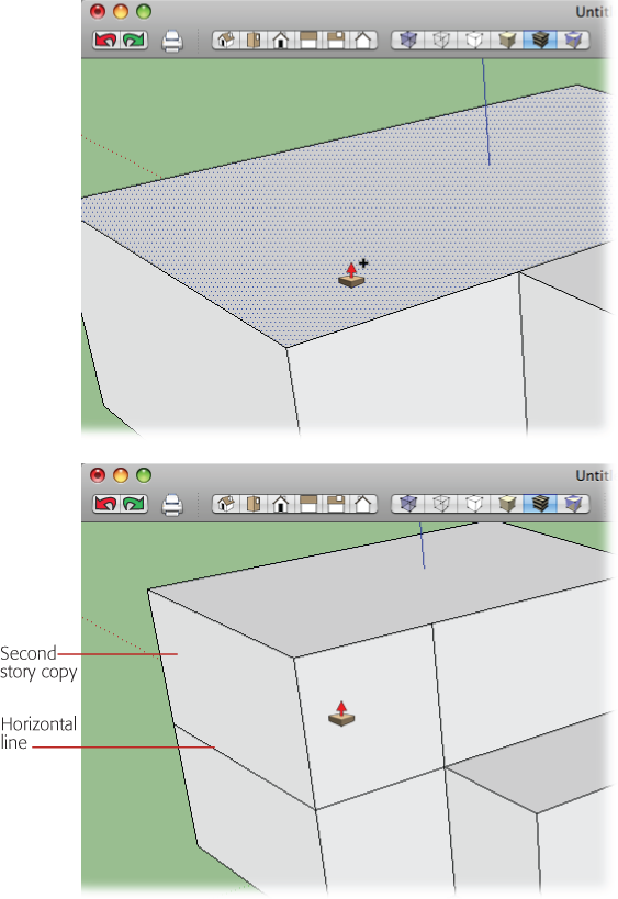
Figure 8-2. Top: While using Push/Pull, press and release the Ctrl key (Option key for Macs), and the tool changes to copy mode. Bottom: Instead of just moving the selected face, Push/Pull makes a copy of the face and uses it for the extrusion. Notice the horizontal line that marks the position of the original face.
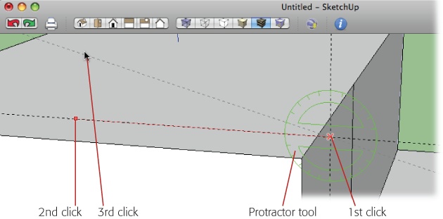
It takes three clicks to place a guide in your model using the Protractor. The first click sets the corner of the angle; or if you think of the 360-degree arc of a circle, that first click is the center of the circle. The second click sets a reference guide. This line isn't permanent; it's only displayed while you're measuring the angle. As you move the cursor between the second and third click, the Measurements toolbar shows (in degrees) the angle between the reference line and your cursor. You can create a guide by clicking, or by entering a value for the angle, as shown in Figure 8-3. Values can be expressed in degrees down to one tenth of a degree. Or, angles can be expressed in architectural slope notation. If you're unfamiliar with that notation, see the box on Using the Follow Me Tool.
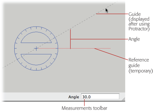
Figure 8-3. The Protractor displays two lines when you're working with it. The reference line, shown as a dotted red line, appears while you're using the Protractor. The second line, a dashed gray line, is the guideline that stays behind when you're done using the protractor.
The Protractor has two modifier keys. If you need a reminder, you find them listed in the status bar hints in the lower-left corner:
Guide Mode (Ctrl for Windows; Option for Macs). As with the Line tool, you can use the protractor to simply measure an angle, or you can use it to place a guide. Press Ctrl (Option) to toggle between the mode that creates guides and the one that doesn't.
Lock Orientation (Shift). When you move the Protractor around your model, it snaps to orient itself with the faces under the cursor, and it displays a color relative to the axis (red, green, or blue). You can lock the Protractor's orientation by pressing and holding Shift before your first click. Then, you're free to move it around the modeling window without the Protractor changing orientation.
In the next few steps, you use the Protractor tool to create the angle of the hipped roof, and then you draw in the profile shape that's used to create the roof.
Tip
The cursor for the Protractor and the Rotate tool are nearly identical, and they're located close to each other on the toolbar. If either tool seems to be misbehaving, double-check to make sure you selected the tool you want.
Choose the Protractor tool and then move it over the different faces of the building.
The cursor automatically orients itself to the faces of the building, and the cursor changes color to indicate an axis.
While the Protractor is colored green, hold down the Shift key.
The Protractor is locked to the green axis. Now you can move the cursor away from the face of the building, and it keeps its orientation and its green color, as shown in Figure 8-4.
Move the center of the Protractor over the point to the right of the building, where the two Tape Measure guides intersect, and then click.
The Protractor tool requires three clicks. The first click marks the center point.
Move along the horizontal construction line and then click again.
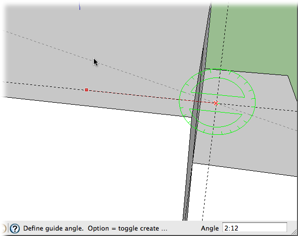
The Protractor (Figure 8-4) displays a line as you move away from the point of that first click. When you click, SketchUp displays a line that's used as a reference as you determine the angle. This line doesn't remain after you're finished with the Protractor.
Figure 8-4. It takes three clicks to create an angled guide using the Protractor tool. The first click creates a center point. Move the cursor away from the center point and click again to establish one line that forms the angle. Move again and click a third time to create the angled guide. The Measurements toolbar (not shown here) displays the angle in degrees.
Release the Shift key and move the cursor up along the blue axis, and then type 2:12.
SketchUp draws the guide at an angle that rises 2 vertical inches for every 12 horizontal inches it spans.
Releasing the Shift key lets you move the cursor off-axis. As you move, SketchUp displays the value of the angle in the Measurements toolbar (Figure 8-5). The value, typed as 2:12, expresses the angle in architectural slope notation. For more details, see the box on Using the Follow Me Tool.
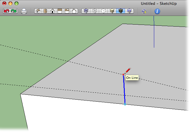
With the Line (L) tool, click the midpoint of the front edge of the roof; then press and release the up arrow key. Move the cursor vertically and then click a second time when the cursor reaches the angled guide that was created by the Protractor.
This line (shown in Figure 8-6) is one edge of the shape that you'll extrude to create the hipped roof.
Continuing with the Line tool, click the point where the two Tape Measure guides intersect.
This point is also the one that you first clicked with the Protractor.
Next move down vertically and find the inference from the top edge of the building.
If necessary you can lock the line on the blue axis by pressing the up arrow key, and then click the corner of the roof.
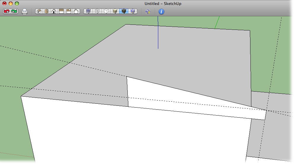
Move the cursor back to the starting point—the midpoint on the front edge of the roof.
The face fills in, forming a roof profile that extends from the eaves to the ridge of the roof, as shown in Figure 8-7.