8.1 Combined Test Voltage
The definitions of combined and composite test voltages are related to the position of the test object to the test voltage sources. When the test object is arranged between the two test systems, a combined voltage stresses the test object via two different HV terminals and to ground (three-electrode test arrangement). When the two test systems are directly connected, a composite voltage is generated stressing the test object from one HV terminal to ground (two-electrode test arrangement). In both cases, each test system must be protected against the voltage generated by the other system by means of an element that lets pass its own voltage and blocks the voltage of the other one (coupling/protecting element).
8.1.1 Generation of Combined Test Voltages
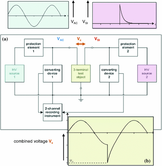
Generation and measurement of combined voltages. a Schematic circuit diagram. b Combined test voltage as a difference of two voltages
The test object is stressed by the difference of the two single voltages (Fig. 8.1a: Vc = VAC − VSI). Figure 8.1b shows as an example the combined test voltage of an AC and a SI voltage. As long as the test object withstands the combined voltage stress Vc, it separates the two HV sources from each other. But when it breaks down, each test system is also stressed by the voltage of the opposite HV source. Then, it must be protected by a suited protection element that blocks the other voltage, at least down to an acceptable voltage stress. But this element must also couple—and not block—the voltage of the protected HV source. This means that elements must be applied that have different impedances for different voltages. For instance, an inductor has no impedance for DC voltage, but an high impedance when stressed with LI voltages. Therefore, it may be used for protecting a DC voltage generator. It must be considered that the coupling/blocking elements influence the two components of the combined voltage. Therefore, the measurement of the two voltages has to be made after the coupling/protecting elements in parallel to the ground insulation of the test object (Fig. 8.1a). Compared with the impedance of the test object, the impedances of the coupling/protecting elements should be low.
Coupling/protecting elements for combined/composite test voltage circuits
Test voltage elements | DC voltage | AC voltage | SI voltage | LI voltage |
|---|---|---|---|---|
Inductors (L) | Coupling | Coupling (L↓) (Protecting, L↑) | Protecting (L↑) (Coupling, L↓) | Protecting |
Resistors (R) | Coupling (R↓) (Protecting, R↑) | Coupling (R↓) (Protecting, R↑) | Protecting (R↑) (Coupling, R↓) | Coupling (only low R↓) |
Capacitors | Protecting | Coupling (C↑) (Protecting, C↓) | Coupling (C↑) (Protecting, C↓) | Coupling |
Switches as triggered gaps, semiconductors | Coupling or protecting | Coupling or protecting | Coupling or protecting | Coupling or protecting |
Example When a DC/LI combined voltage shall be applied, the right element between DC voltage test system and test object is an inductor, because it couples the DC voltage and protects against LI voltage. Between the LI test system and the test object, a capacitor is the right element, it couples the LI voltage and protects the impulse generator against a DC voltage stress. Also the application of a (-possibly triggered-) sphere gap can be taken into consideration.
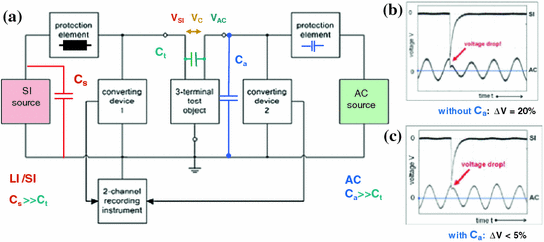
Interaction between the two voltage sources. a Schematic circuit diagram. b Drop of the AC voltage without supporting capacitor. c Drop of the AC voltage with supporting capacitor Ca
8.1.2 Requirements to Combined Test Voltages

Time delay of combined and composite voltages. a For two impulse voltages. b For an impulse voltage and an AC voltage
8.1.3 Measurement of Combined Test Voltages
The two HV test systems require a HV measuring system each for the adjustment of their output voltages that contribute to the combined or composite voltage. These measuring systems must be able to record also the interactions between the two HV test systems.
The stressing combined voltage acts between the HV terminals of the test object (Fig. 8.1). A usual measurement of this voltage is difficult because there is no earth potential involved. IEC 60060-1:2010 allows therefore the calculation of the combined test voltage from the measurement of its two voltage components: Each of the two voltage dividers shall be arranged as near as possible to its relevant HV terminal of the test object. The two voltages are recorded, and the combined voltage is calculated as its difference. The uncertainty estimation for the measurement of the calculated combined voltage must consider the influences of the test object and of voltage drops over the connection/blocking elements the calculated one (Fig. 8.1b), should be displayed using an identical time scale.
8.1.4 Examples for Combined Voltage Tests
Disconnector testing : The testing of EHVAC disconnectors and phase-to-phase air insulation with a combined voltage of AC and SI components is the classical example of a combined voltage test. The interaction between the test voltage sources may cause a voltage drop as considered above in Sect. 8.1.1 (Fig. 8.2). Garbagnati et al. (1991) found that the atmospheric corrections of IEC 60060-1 (see Sect. 2.1.2) deliver sufficient results when they refer to that component of the test voltage value between the HV terminals that causes the maximum of the combined voltage.

DC/SI combined voltage. a Circuit with coupling/connecting elements. b OLI voltage superimposed on DC voltage
8.2 Composite Voltages
8.2.1 Generation and Requirements
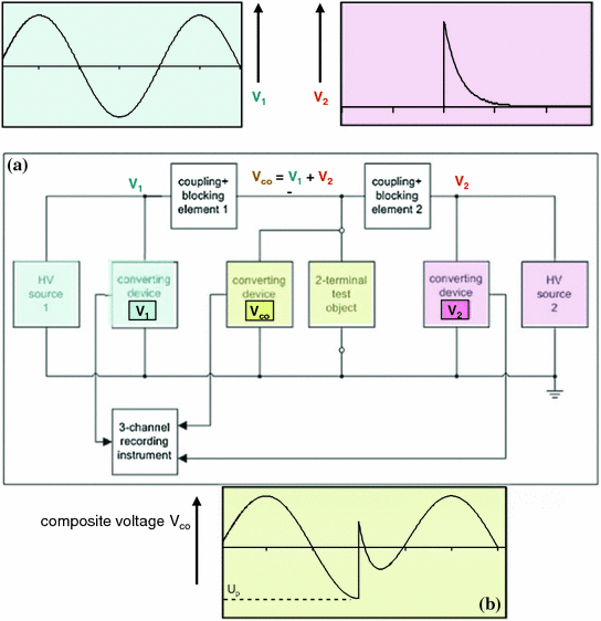
Generation and measurement of composite voltages. a Schematic circuit diagram. b Composite voltage as the sum of the two voltages
The test voltage value of the composite voltage is the maximum absolute value at the test object and shall meet the specified value within ±5%. Also any voltage drop shall not exceed 5%. The time delay is defined as for combined voltages (Fig. 8.3) and should be again within ±0.05 Tp (Tp as defined in Sect. 8.1.1). For the single-voltage components, the requirements in the relevant chapters of this textbook shall be applied.
8.2.2 Measurement of Composite Test Voltages
The stressing composite voltage acts between the HV terminal of the test object and the earth (Fig. 8.5). Therefore, it can be measured directly. The used measuring system shall fulfil the requirements of IEC 60060-2:2010 for both components. In case of a DC/LI composite voltage, e.g. an universal divider has to be applied (Fig. 2.10). The separate measurement of the two voltage components is necessary for the precise control of the two test voltage generators and for the verification of the correct relation of the two test voltages. All three voltages shall be recorded synchronously and displayed with an identical time scale (Fig. 8.5).The voltage measuring systems shall be calibrated for the measurement for the related voltage components as well as for the composite voltages to be measured. Based on that the uncertainty of the measurement of the composite voltages shall be estimated.
8.2.3 Examples for Composite Voltage Tests
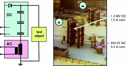
Test system for DC/AC composite voltage up to ±1300 kV DC and 400 kV AC (The principle is shown for one polarity only)
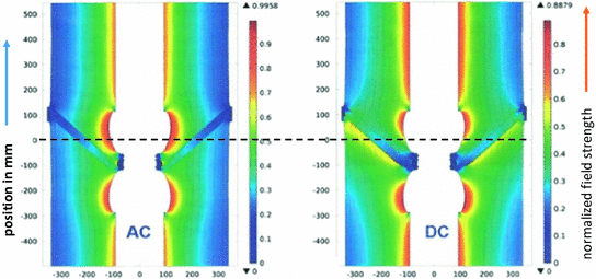
Field conditions in an HVAC and an HVDC gas-insulated system before a transient stress (Hering et al. 2017). Consider the higher field strength on the outer side of the spacer at DC stress

Composite DC/LI voltage tests as definition for the LI voltage tests of a gas-insulated system (schematically) as proposed in CIGRE JWG D1/B3.57 2017. The blocking/connecting element is a triggered spark gap, causing a voltage jump when triggered (dotted blue lines). a Composite voltage of positive DC and positive LI component. b Composite voltage of positive DC and negative LI component. c Composite voltage of negative DC and negative LI component. d Composite voltage of negative DC and positive LI component
NOTE Fig. 8.8 is a proposal of the CIGRE JWG D1/B3.57 for the present draft of a CIGRE Brochure. It uses Fig. 8.8 for definitions of LI test voltages and defines separately a DC voltage pre-stress. It underlines the high LI stress when the two voltage components are of opposite polarity. But it seems to be better to consider the composite voltage because the two stresses act commonly.
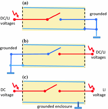
Testing of a the switching device of a SF6-insulated system (schematically). a DC/LI or SI composite voltage test, right side grounded. b DC/LI or SI composite voltage test, left side grounded. c DC/LI or SI combined voltage test